

Page 1
BL - Control
900 Serie
Bedienungsanleitung Seite 2-9
쮕
Operating Instructions Page 10-17
Notice d’utilisation Page 18-25
Istruzioni per l’uso Pagina 26-33
Manual de uso Página 34-41
CZ
Návod k obsluze Strana 42-49
Page 2

Inhalt
1. Einführung ............................................................... 2
1.1. Sicherheitshinweise ................................................. 2
1.2. Gewährleistung/Haftungsausschluss ......................... 2
1.3. CE-Konformitätserklärung ......................................... 2
쮕
1.4. Entsorgung .............................................................. 3
2. Anschluss und Besonderheiten ................................. 3
3. Technische Daten .................................................... 3
4. Programmierung der Knüppelpositionen .................... 4
5. Programmierung von Reglerparametern
ohne Programmer .................................................... 5
5.1. Merkmale und Schutzfunktionen ............................... 6
5.2. Programmierbeispiel ................................................ 6
6. Einstellungen mit Programmer .................................. 7
6.1. Übersicht der Programmierungsmöglichkeiten ........... 7
7. Details zur Programmierung ...................................... 8
1. Einführung
Kleine, leichte Fahrtreglerserie in neuer Cool Power FET Technologie, dadurch besonders leistungsfähig und mit breitem Einsatzbereich, für Flug,- Schiffs,- Auto,- und E-Heli-Modelle einsetzbar. Die Regler eignen sich besonders für die BL Motoren-Serie
ROXXY, aber auch für andere BL-Motoren. Vor Anschluss und Inbetriebnahme diese Anleitung bitte aufmerksam lesen.
1.1. Sicherheitshinweise
- Beachten Sie die technischen Daten des Reglers.
- Polung aller Anschlusskabel beachten.
- Kurzschlüsse unbedingt vermeiden.
- Den Regler so einbauen bzw. verpacken, dass er nicht mit
Fett, Öl oder Wasser in Berührung kommen kann.
- Für ausreichende Luftzirkulation sorgen.
- Bei Inbetriebnahme nie in drehende Teile greifen Verletzungsgefahr.
- Motoren sicher befestigen.
Technische Änderungen vorbehalten.
1.2. Gewährleistung/Haftungsausschluss
Die Firma MULTIPLEX Modellsport GmbH & Co.KG übernimmt
keinerlei Haftung für Verluste, Schäden oder Kosten, die sich
aus fehlerhafter Verwendung und Betrieb ergeben oder in
irgendeiner Weise damit zusammenhängen. Soweit gesetzlich
zulässig, ist die Verp ichtung der Firma MULTIPLEX Modellsport
GmbH & Co.KG zur Leistung von Schadenersatz, gleich aus
welchem Rechtsgrund, begrenzt auf den Rechnungswert der an
dem schadenstiftenden Ereignis unmittelbar beteiligten Warenmenge der Firma MULTIPLEX Modellsport GmbH & Co.KG.
Dies gilt nicht, soweit die MULTIPLEX Modellsport GmbH & Co.KG
nach zwingenden gesetzlichen Vorschriften wegen Vorsatzes oder
grober Fahrlässigkeit unbeschränkt haftet.
Für unsere Produkte leisten wir entsprechend den derzeit geltenden gesetzlichen Bestimmungen Gewähr. Wenden Sie sich mit
Gewährleistungsfällen an den Fachhändler, bei dem Sie das Produkt erworben haben. Von der Gewährleistung ausgeschlossen
sind Fehlfunktionen, die verursacht wurden durch:
· Unsachgemässen Betrieb
· Falsche, nicht oder verspätete, oder nicht von einer
autorisierten Stelle durchgeführte Wartung
· Falsche Anschlüsse
· Verwendung von nicht originalem MULTIPLEX/HiTEC-Zubehör
·
Veränderungen/Reparaturen, die nicht von MULTIPLEX
einer MULTIPLEX-Servicestelle ausgeführt wurden
· Versehentliche oder absichtliche Beschädigungen
· Defekte, die sich aus der normalen Abnutzung ergeben
· Betrieb ausserhalb der technischen Spezi kationen
Zusammenhang mit Komponenten anderer
MULTIPLEX Modellsport GmbH & Co.KG
Westliche Gewerbestrasse 1 · D-75015 Bretten-Gölshausen
Multiplex/HiTEC Service: +49 (0) 7252 - 5 80 93 33
oder
oder im
Hersteller.
1.3. CE-Konformitätserklärung
Die Bewertung des Gerätes erfolgte nach europäisch harmonisierten Richtlinien. Sie besitzen daher ein Produkt, das hinsichtlich der
Konstruktion die Schutzziele der Europäischen Gemeinschaft zum sicheren Betrieb der Geräte erfüllt. Die Konformitätserklärung des
Gerätes kann bei der MULTIPLEX Modellsport GmbH & Co.KG angefordert werden.
2
Page 3
1.4. Entsorgung
Elektrogeräte, die mit der durchgestrichenen Mülltonne gekennzeichnet sind, zur Entsorgung nicht in den Hausmüll geben, sondern einem geeigneten Entsorgungssystem zuführen.
In Ländern der EU (Europäische Union) dürfen Elektrogeräte
nicht durch den Haus- bzw. Restmüll entsorgt werden (WEEE
- Waste of Electrical and Electronic Equipment, Richtlinie
2002/96/EG).
2. Anschluss und Besonderheiten
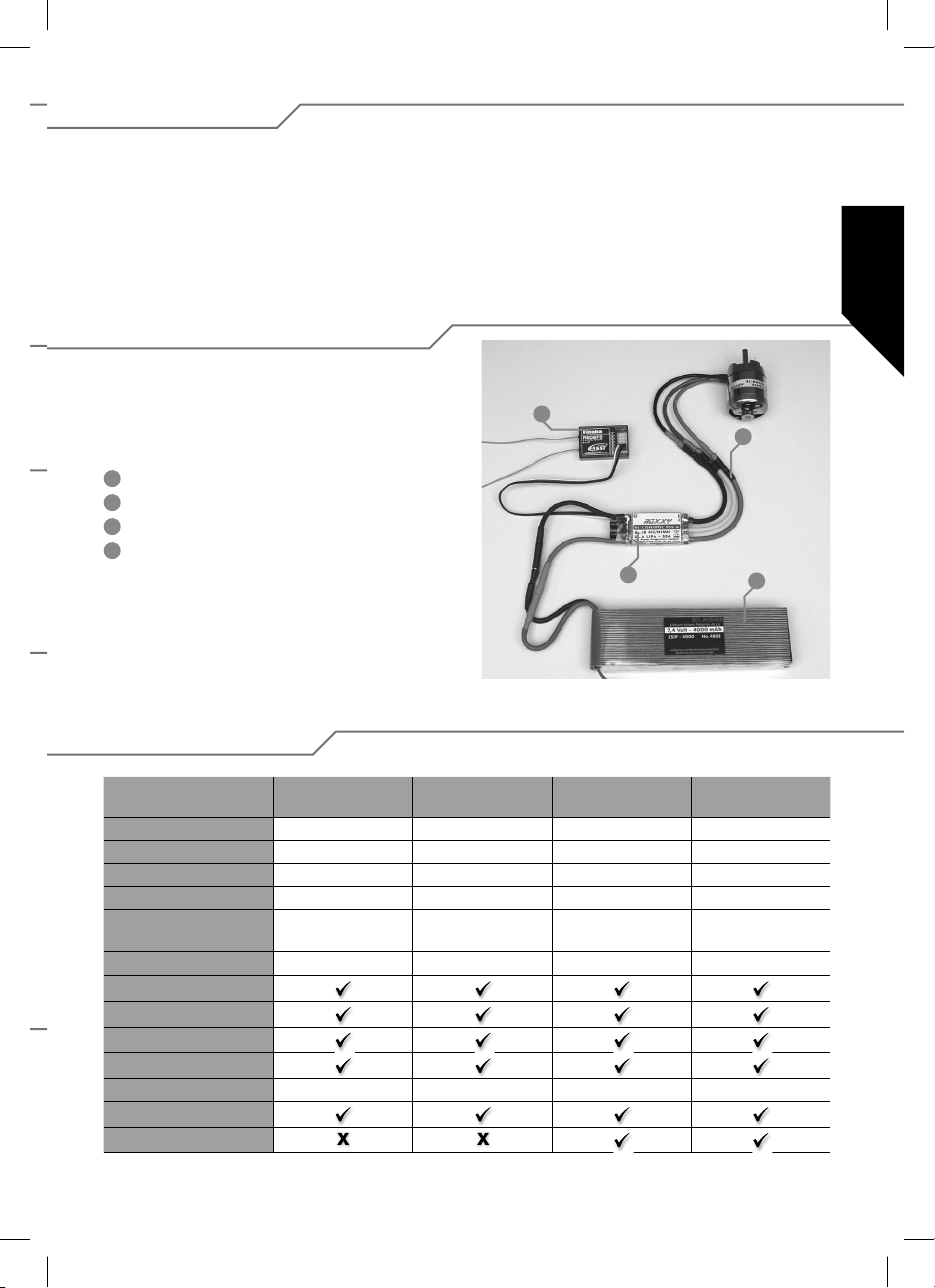
Das rote Kabel (plus) und das schwarze Kabel (minus) durch
Verwendung eines geeigneten Stecksystems für den Anschluss
an den Antriebsakku vorbereiten. Alle Lötstellen mit Schrumpfschlauch isolieren.
1
Emp fän ger
2
Motoranschluss
3
Fahrtregler
4
Antriebsakku
Sie können Ihr Altgerät bei öffentlichen Sammelstellen Ihrer
Gemeinde bzw. Ihres Wohnortes (z. B. Recyclinghöfe) abgeben. Das Gerät wird dort für Sie fachgerecht und kostenlos
entsorgt. Mit der Rückgabe Ihres Altgerätes leisten Sie einen
wichtigen Beitrag zum Schutz der Umwelt!
1
2
3
4
쮕
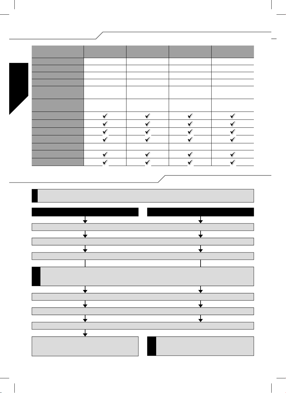
3. Technische Daten
BL 908
Nr. 31 8627
Laststrom 8 A 18 A 30 A 30 A
Kurzzeit 12 A 22 A 35 A 35 A
Abmessungen (mm) 35 x 22 x 7 38 x 22 x 7 49 x 25 x 10 49 x 25 x 10
Gewicht (g) 15 g 25 g 29 g 29 g
Zellenzahl 6...12 NC/NiMh
2...4 LiPo
BEC 5,5 Volt max. 2 A 5,5 Volt max. 2 A 5,5 Volt max. 2 A 5,5 Volt max.2 A
SPS
Rx-Filter
PCO
POR
hec 32 kHz 32 kHz 32 kHz 32 kHz
TP
Cool Power FET
BL 918
Nr. 31 8628
6...12 NC/NiMh
2...4 LiPo
BL 930
Nr. 31 8629
6...12 NC/NiMh
2...4 LiPo
BL 930-6
Nr. 31 8630
6...18 NC/NiMh
2...6 LiPo
3
Page 4
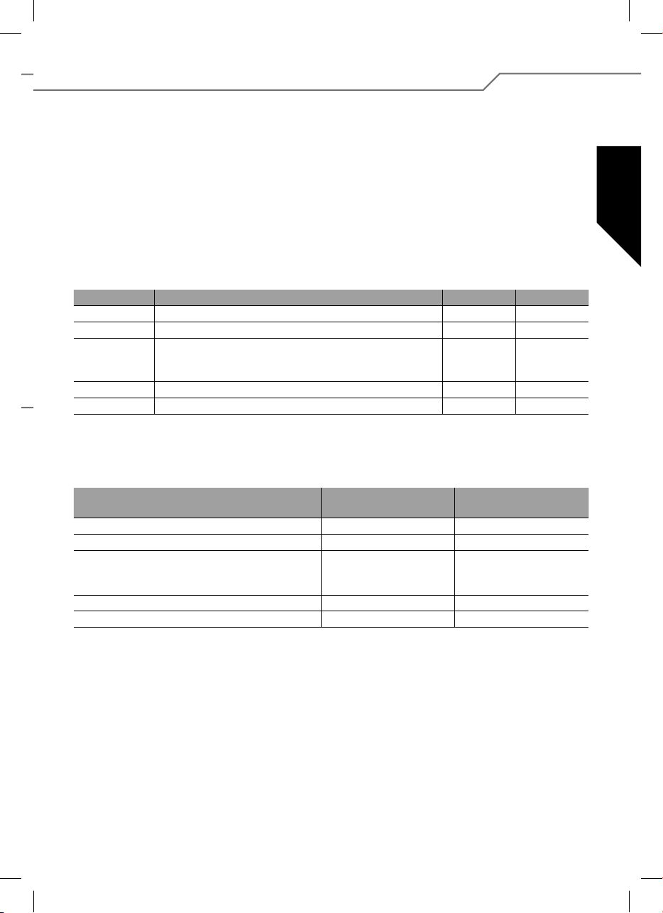
3. Technische Daten
BL 940-6
Nr. 31 8631
Laststrom 40 A 50 A 60 A 100 A
Kurzzeit 50 A 60 A 70 A 110 A
쮕
Abmessungen (mm) 66 x 25 x 10 66 x 25 x 10 66 x 25 x 10 76 x 26 x 13
Gewicht (g) 47 g 49 g 49 g 67 g
Zellenzahl 6...18 NC/NiMh
BEC 5,5 Volt
SPS
Rx-Filter
PCO
POR
hec 32 kHz 32 kHz 32 kHz 32 kHz
TP
Cool Power FET
2...6 LiPo
max. 3 A/kurz. 5 A
BL 950-6
Nr. 31 8632
6...18 NC/NiMh
2...6 LiPo
5,5 Volt
max. 3 A/kurz 5 A
BL 960-6
Nr. 31 8634
6...18 NC/NiMh
2...6 LiPo
5,5 Volt
max. 3 A/kurz. 5 A
4. Programmierung der Knüppelpositionen
Soll eine Änderung des Modelltyps (Parameter 4 oder Parameter 5) erfolgen, muss dieser Parameter vor der Änderung
!
anderer Parameter eingestellt werden.
Vorwärts, Stopp und Rückwärts Vorwärts und Stopp (Modelltyp Air u. Heli)
BL 9100-6
Nr. 31 8635
6...18 NC/NiMh
2...6 LiPo
5,5 Volt
max. 3 A/kurz. 5 A
1. Regler gemäß Anschlusszeichnung anschließen (außer der Spannungsversorgung).
2. Sender einschalten und Gasknüppel in die Vorwärtsposition bringen.
3. Spannungsversorgung an den Regler anschließen.
Falls nach (Punkt 2) die LED leuchtet, muss am Sender SERVOREVERSE betätigt werden, die Spannungsversorgung zum
Regler unterbrochen und erneut mit (Punkt 1) begonnen werden. Die Vorwärtsposition des Knüppels muss in der Nähe des
!
mechanischen Anschlags stehen.
4. Der Regler bestätigt mit einer kurzen Tonfolge.
5. Nach ca. 10 Sekunden ertönt eine Doppeltonfolge als Bestätigung für erfolgreiche Programmierung der Vorwärtsposition.
6. Gasknüppel in die Stopposition bringen, eine kurze Tonfolge bestätigt die erfolgreiche Programmierung der Stopposition.
7. Gasknüppel in die Rückwärtsposition bringen, eine Dreifachtonfolge bestätigt die erfolgreiche Programmierung
der Stopposition.
Die Programmierung der Knüppelpositionen Vorwärts
und Stopp von nur Vorwärtsreglern erfolgt analog bis zu
!
(Punkt 6), die mit einer Dreifachtonfolge bestätigt wird.
4
Page 5
5. Programmierung von Reglerparametern ohne Programmer
Es können fünf Parameter programmiert werden.
Der Eintritt in den Programmiermodus erfolgt durch:
1. Regler gemäß Anschlusszeichnung anschließen
(außer der Spannungsversorgung).
2. Sender einschalten und Gasknüppel in die Vorwärts position bringen.
3. Spannungsversorgung an den Regler anschließen.
4. Der Regler bestätigt mit einer kurzen Tonfolge.
5. Nach ca. 10 Sekunden ertönt eine Doppeltonfolge,
nach weiteren ca. 3 Sekunden ertönt eine Dreifachtonfolge.
Der Regler zeigt jetzt durch kontinuierliches einmaliges Piepsen
und Blitzen der LED die Auswahl von Parameter 1 an.
Parametertyp Beep LED
Parameter 1
Parameter 2
Parameter 3
Parameter 4
Parameter 5
Zum Ändern des Parameters ist zunächst ein Wechsel des
Gasknüppels aus der Vorwärtsposition in die Stopposition erforderlich, der Gasknüppel muss mindestens 3 Sekunden in
der Stopposition verweilen.
Parametertyp LED EIN
Batterietyp
Drehrichtung
Bremse (AIR)
Governor (HELI)
Rückwärts (CAR, BOOT)
Modelltyp (AIR/HELI)
Modelltyp (BOOT/CAR)
Batterietyp 1 x 1 x
Drehrichtung 2 x 2 x
- Bremse EIN/AUS (AIR)
- Governor EIN/AUS (HELI)
- Rückwärts EIN/AUS (CAR, BOOT)
Modelltyp AIR/HELI 4 x 4 x
Modelltyp BOOT/CAR 5 x 5 x
Die Auswahl der zu programmierenden Parameter erfolgt
durch folgende Gasknüppelsequenz: Kurzer Wechsel des
Gasknüppels aus der Vorwärtsposition in die Stopposition und
zurück in die Vorwärtsposition. Der Regler zeigt jetzt durch
kontinuierliches zweimaliges Beepen und Blinken der LED die
Auswahl von Parameter 2 an.
Für die Auswahl der Parameter 3, 4 und 5 muss die oben
beschriebene Gasknüppelsequenz wiederholt angewandt werden.
Die eigentliche Änderung des Parameters selbst, erfolgt durch
einen schnellen Wechsel des Gasknüppels aus der Stopposition
in die Vorwärtsposition und zurück.
Beep alle 2 Sek.
LiPo NiCD/NiMH
Normal Reverse
AUS
AUS
AUS
AIR HELI
BOOT CAR
쮕
3 x 3 x
LED blinkt
Beep alle 0,5 Sek.
EIN
EIN
EIN
Das Abspeichern der Änderung erfolgt durch einen Wechsel
des Gasknüppels von der Stopposition in die Vorwärtsposition.
Das Beenden und Übernehmen der Programmiereinstellungen
wird durch Unterbrechen der Spannungsversorgung gespeichert.
Der Regler ist programmiert und betriebsbereit.
5
Page 6
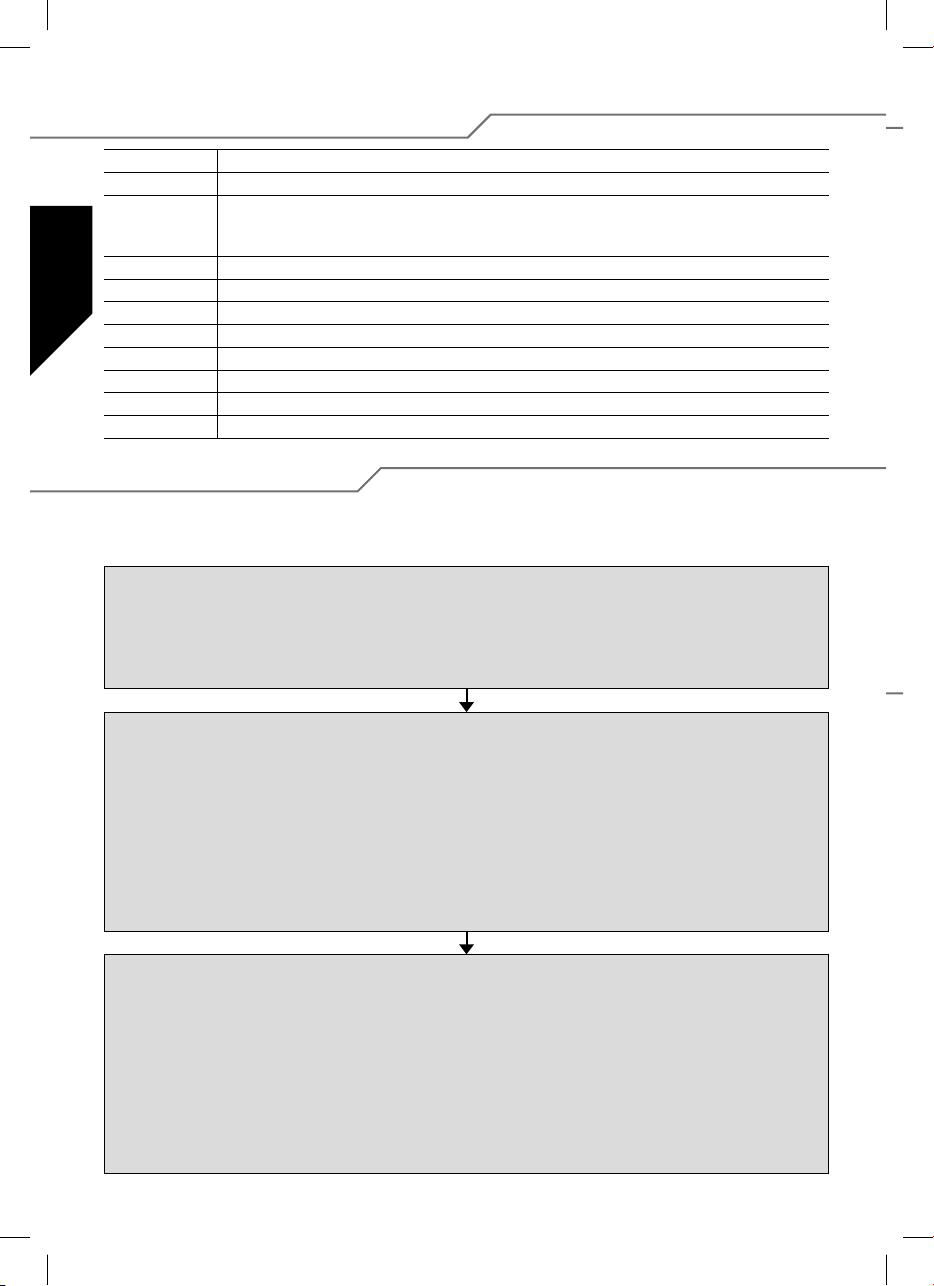
5.1. Merkmale und Schutzfunktionen
BEC Empfängerstromversorgung
POR
PCO Unterspannungsabschaltung, der Motor wird bei entleertem Akku rechtzeitig abgeschaltet, um genügend
쮕
hec Hohe Taktfrequenz zur feinfühligen, magnetschonenden Motoransteuerung.
SPS Super Programming System
Cool Power FET Neue Transistoren Generation
WP Spritzwassergeschützt (Water Protect)
Opto Galvanische Trennung zwischen Motorstörungen und Empfänger.
RX-Filter Schaltet den Regler bei fehlendem oder ungültigem Sendersignal aus.
TOP Doppelter Überlastungschutz (Thermal Overload Protection)
TP Thermische Sicherung (Thermal Protection)
Anlaufschutz, verhindert ungewolltes Anlaufen des Motors.
Kapazität für die Steuerung zu reservieren und um eine Tiefentladung des Akkus zu vermeiden (wahlweise
für NC/NiMH oder Lipoly-Akku).
5.2. Programmierbeispiel
Im nachfolgenden Beispiel wird die Anpassung des Reglers an die individuelle Knüppelposition und nachfolgend die
Programmierung des Modeltyps: AIR und Bremse ON erläutert.
Programmierung der Knüppelpositionen
1. Sender einschalten und Gasknüppel in die gewünschte Vorwärtsposition bringen.
2. Spannungsversorgung an den Regler anschließen (kurze Tonfolge ertönt).
3. Nach ca. 10 Sekunden ertönt eine Doppeltonfolge als Bestätigung für erfolgreiche Programmierung der Vorwärtsposition.
4. Gasknüppel in die Stopposition bringen, eine kurze Tonfolge bestätigt die erfolgreiche Programmierung der Stopposition.
5. Spannungsversorgung, unterbrechen.
Programmierung der Reglerparameter
1. Sender einschalten und Gasknüppel in die Vorwärtsposition bringen.
2. Spannungsversorgung an den Regler anschließen (kurze Tonfolge ertönt).
3. Nach ca. 10 Sekunden ertönt eine Doppeltonfolge, nach weiteren ca. 3 Sekunden ertönt eine Dreifachtonfolge.
4. Jetzt be ndet sich der Regler im Programmiermodus Parameter 1 (kontinuierliches einmaliges Piepsen und blinken der LED).
5. Durch viermaligen Wechsel des Gasknüppels aus der Vorwärtsposition in die Stopposition und zurück in die Vorwärtsposition,
gelangt man zu Parameter 4 (kontinuierliches viermaliges Beepen und viermaliges LED blinken).
6. Zum Ändern des Parameters ist zunächst ein Wechsel des Gasknüppels aus der Vorwärtsposition in die Stopposition
erforderlich. Der Gasknüppel muss mindestens 3 Sekunden in der Stopposition verweilen.
7. Den Mode Air (LED leuchtet/Beep alle 2 Sek.) auswählen.
8. Das Abspeichern erfolgt durch einen Wechsel des Gasknüppels von der Stopposition in die Vorwärtsposition.
Air Brake On einstellen
1. Nach obigem Abspeichern be ndet sich der Regler wieder im Parameterauswahl Parameter 4.
2. Durch viermaligen Wechsel des Gasknüppels aus der Vorwärtsposition in die Stopposition und zurück in die Vorwärtsposition,
gelangt man zu Parameter 3 (kontinuierliches dreimaliges Beepen und dreimaliges LED blinken).
3. Zum Ändern des Parameters ist zunächst ein Wechsel des Gasknüppels aus der Vorwärtsposition in die Stopposition
erforderlich. Der Gasknüppel muss mindestens 3 Sekunden in der Stopposition verweilen.
4. Jetzt wird die aktuell eingestellte Funktion der Bremse angezeigt. Air Brake ON (LED blinkt/Beep alle 0,5 Sek.) oder
Air Brake OFF (LED leuchtet/Beep alle 2 Sek.). Gegebenenfalls Parameter, mit schnellem Wechsel des Gasknüppels von
der Stopposition in die Vorwärtsposition und zurück, ändern.
5. Das Abspeichern der Änderung erfolgt durch einen Wechsel des Gasknüppels von der Stopposition in die Vorwärtsposition.
6. Spannungsversorgung, unterbrechen.
6
Page 7
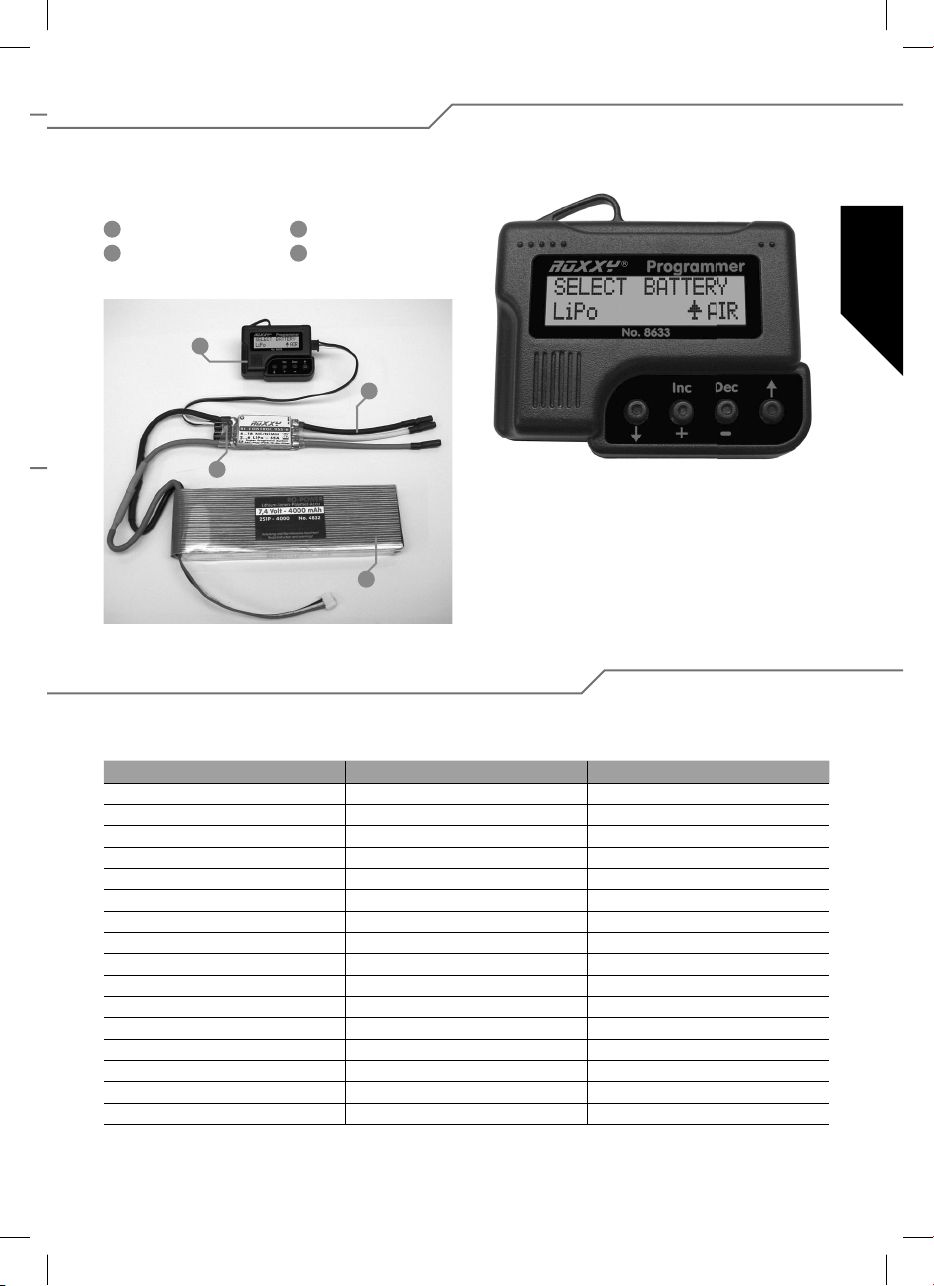
6. Einstellungen mit Programmer
Um den Regler einfacher und modellspezi scher zu programmieren, nutzen Sie den Programmer Nr. 31 8633. Diese übersicht-
liche Bedieneinheit ermöglicht es Ihnen über ein LC-Display, die einzustellenden Parameter schnell und sicher zu programmieren.
1
Programmer
2
Motoranschluss
1
3
3
Fahrtregler
4
Antriebsakku
2
Navigation mit Programmer
Die Bedienung des Programmers ist denkbar einfach. Mit den
äußeren Pfeiltasten entweder nach unten oder nach oben
springen um in den Programmier-Modi ihrer Wahl zu gelangen.
Außerdem wechselt man mit ihnen den Modeltyp, indem man
4
beide Pfeiltasten gedrückt hält. Die beiden mittleren Tasten
DEC (–) und INC (+), dienen zur Auswahl bzw. zum Ändern
einer Einstellung.
6.1. Übersicht der Programmierungsmöglichkeiten
Bis auf wenige Unterschiede sind im wesentlichen alle Programmpunkte gleich gestaltet. Zum besseren Verständnis sind alle
Werte in der untenstehenden Tabelle aufgelistet.
Heli Boot/Car (Schiff-Auto) Air (Flug)
Select Battery (Batterietyp) Select Battery (Batterietyp) Select Battery (Batterietyp)
Cut Off Voltage (Abschaltspannung) Cut Off Voltage (Abschaltspannung) Cut Off Voltage (Abschaltspannung)
Cut Off Type (Motor Aus Typ) Cut Off Type (Motor Aus Typ) Cut Off Type (Motor Aus Typ)
Motor Direction (Motorlaufrichtung) Motor Direction (Motorlaufrichtung) Motor Direction (Motorlaufrichtung)
Advance Timing (Motor Timing) Advance Timing (Motor Timing) Advance Timing (Motor Timing)
Acceleration (Beschleunigung) Acceleration (Beschleunigung) Acceleration (Beschleunigung)
Start Power Start Power Start Power
Governor On/Off (Drehzahlreg. Ein/Aus) Reverse Function Air Brake Type (Motorbremstyp)
Response of Governor (Regelcharakteristik) Motor pole Num (Motorpolzahl) Airbrake On/Off (Motorbremse Ein/Aus)
Motor pole Num (Motorpolzahl) Gear Ratio (Getriebeuntersetzung) Motor pole Num (Motorpolzahl)
Gear Ratio (Getriebeuntersetzung) Max. RPM (max. Drehzahl Anzeige) Gear Ratio (Getriebeuntersetzung)
Max. RPM (max. Drehzahl Anzeige) Average RPM (Durchschnittliche Drehzahl) Max. RPM (max. Drehzahl Anzeige)
Average RPM (Durchschnittliche Drehzahl) Down Load (Daten schreiben) Average RPM (Durchschnittliche Drehzahl)
Down Load (Daten schreiben) Restore Mem. (Progr. Daten lesen) Down Load (Daten schreiben)
Restore Mem. (Progr. Daten lesen) Backup Mem. (Sicherungskopie) Restore Mem. (Progr. Daten lesen)
Backup Mem. (Sicherungskopie) Backup Mem. (Sicherungskopie)
쮕
7
Page 8
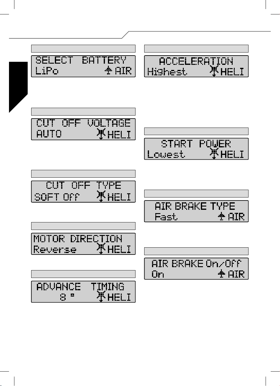
7. Details zur Programmierung
1. Battery Type (Batterietyp)
쮕
Um den gewünschten Akku Typ einzustellen nutzen Sie die DEC oder
INC Taste. Nachdem Sie den neuen Akkutyp gewählt haben, kann es
sein, dass sich voreingestellte Parameter im Bereich “CUT OFF VOLTAGE”
und “CUT OFF TYPE” verändert haben. Einzustellen sind die Modi immer
durch die DEC und INC Tasten.
2. Cut Off Voltage (Abschaltspannung)
Die Cut Off Voltage (Abschaltspannung) richtet sich nach dem eingestellten Akkutyp. Bei einem Lipo Akku im Auto Modi, schaltet der Regler
bei 3 V pro Zelle ab, bei einem NiCd Akku allerdings schon bei 5,5 V
(Abschaltungsart einstellbar). Sie können aber auch mit Hilfe der DEC und
INC Tasten den Wert selbst einstellen. Die Skala reicht von 4,5 V-33,0 V.
3. Cut Off Type (Motor-Abschalt Typ)
Im Cut Off Type Mode können Sie den Abschalttyp bei einer evtl. Unterspannung einstellen. Verwendet werden können “Soft Off” oder “Hard
Off”. Einzustellen sind die Modi wieder durch die DEC und INC Tasten.
4. Motor Direction (Motorlaufrichtung)
Im Modus Motor Direction (Motor Laufrichtung) können Sie zwischen
der normalen oder umgedrehten Laufrichtung Ihres Motors entscheiden.
6. Acceleration (Beschleunigung)
Im Acceleration (Beschleunigung)-Modus wird eingestellt, wie schnell
der Regler auf den Maximalwert läuft. Dies ist wichtig, wenn die Gasfunktion mit einem Schalter betätigt wird, um die Verzögerung festzulegen mit welcher Geschwindigkeit auf “Vollgas” geschaltet wird.
Beispiel: Lowest/geringste Beschleunigung oder Highest/höchste
Beschleunigung.
Einstellbare Parameter:
Lowest / Low / Normal / High / Highest (sehr niedrig / niedrig / normal /
hoch / sehr hoch) bedienung über DEC und INC Tasten.
7. Start Power
Im Menü Start Power wird die Startleistung (Kraftmoment) eingestellt,
mit dem der Motor (aus dem Stillstand) losläuft. Besonders beim Einsatz in Helis sind kleine Werte zu wählen um das Zahnrad zu schonen.
Eingestellt werden kann Lowest / Low / Normal / High / Highest (sehr
niedrig / niedrig / normal / hoch / sehr hoch).
8. Air Brake Type (Motorbremstyp) - nur Air Mode!
Im Air Mode (Flugmodell) kann die Wirkung der Motorbremse eingestellt
und somit bestimmt werden, ob der Motor sanft oder hart (schlagartig)
zum Stillstand kommt. Wählbar sind die Modi: Slow / Normal / Fast
(Sanft - Normal - Hart), über die Tasten DEC und INC.
9. Air Brake On/Off (Motorbremse Ein/Aus) nur Air Mode
5. Advance Timing (Motor-Timing)
Das Advance Timing ist als Motor Timing zu verstehen. Mit dieser Einstellung kann man ein Vorlaufen des Drehfeldes bewirken, welches
eine “Frühzündung” bewirkt. Im Allgemeinen sind 8° für die meisten
Motoren geeignet. Um ein spezielles Setup für Ihren Motor einzustellen,
empfehlen wir folgende Werte: 0°-10° Inrunner Motoren, 15°-25°
Outrunner Motoren.
8
In diesem Menüpunkt kann die Motorbremse wahlweise ein- oder ausgeschaltet werden.
Page 9
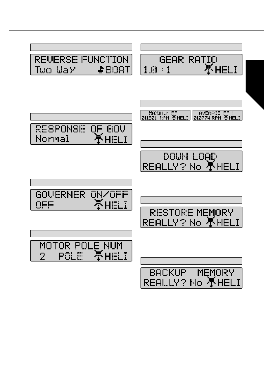
10. Reverse Function (Nur Im Boot+Car Mode!)
14. Gear Ratio (Getriebeuntersetzung)
쮕
Mit der Reverse Function kann im Boot oder Car Modus gewählt werden, ob der Motor nur in eine Laufrichtung oder Vorwärts/Rückwärts
arbeitet. Im Modus “One Way” (eine Richtung) wird die Laufrichtung des
Motors festgelegt – Vorwärts oder Rückwärts. Im “Two Way Modus” ist
der Regler für den Vorwärts/Rückwärts-Betrieb eingestellt.
Achtung: Einstellungen können sich bei Änderung der Motorlaufrichtung (Motor Direction) aufheben.
11. Response of Governor (Regelcharakteristik) nur Heli
In diesem Modus wird die Regelcharakteristik des Drehzahlreglers eingestellt. Wählbar sind die Bereiche Slowest / Slow / Normal / Fast /
Fastest (sehr langsam, langsam, normal, schnell, sehr schnell).
Achtung: Je schneller der gewählte Wert ist, umso mehr Strom wird
vom Akku benötigt. Um den Regler bzw. Akku zu schonen und die Flugzeit zu erhöhen wählen Sie eine niedrigere Einstellung.
12. Governor On/Off (Drehzahlregl. Ein/Aus) nur Heli
In diesem Menü wird der Drehzahlregler ein-oder ausgeschaltet. Dieser
stablisiert die voreingestellte Drehzahl und hält diese nahezu konstant.
Modus On (EIN) für stabilisiert oder Off (AUS) für nicht stabilisiert.
13. Motor Pole Number (Motorpolzahl)
Im Motor Pole Number Mode können Sie einstellen, über wie viele Pole
Ihr Motor verfügt. Dieser Wert ist wichtig, um die genaue Drehzahl anzuzeigen. Der einstellbare Wert reicht von 2 bis 36 Pole.
In dieser Einstellungsebene können Sie Ihre individuelle Getriebeübersetzung eingeben. In Abhängigkeit mit der Motorpolzahl und der Getriebeuntersetzung wird der Wert für die Drehzahlanzeige berechnet. Die
einstellbaren Werte gehen von 1,0 : 1 bis 25,0 : 1.
15. Max. RPM & Average RPM (Drehzahl-Anzeige)
Dieser Modi zeigt Ihnen die maximale und die durchschnittliche Drehzahl des letzten Fluges unter Berücksichtigung der eingestellten Werte
von Punkt 14 und 15 an.
16. Down Load (Daten schreiben)
Mit dem Down Load schreiben Sie die eingestellten Werte auf den
Regler. Mit der INC Taste starten Sie die Anwendung, der Programmer
beept dazu jede Sekunde bis die Anwendung beendet ist. Falls Sie den
Vorgang abbrechen wollen, drücken Sie DEC.
17. Restore Memory (Programmer Daten lesen)
Mit dem Restore Memory öffnen Sie die gespeicherten Werte, die auf
dem Programmer eigenen Speicher gespeichert wurden. Mit der INC
Taste starten Sie die Anwendung, der Programmer beept dazu jede Sekunde bis die Anwendung beendet ist. Falls Sie den Vorgang abbrechen
wollen, drücken Sie DEC.
18. Backup Memory (Sicherungskopie)
Im Backup Memory speichern Sie die eingestellten Werte auf dem
Speicher, der sich im Programmer be ndet. Mit der INC Taste starten
Sie die Anwendung, der Programmer beept dazu jede Sekunde bis die
Anwendung gespeichert ist. Die eingestellten Werte auf dem Regler
werden dabei nicht beeinträchtigt. Falls Sie denn Vorgang abbrechen
wollen, drücken Sie DEC.
9
Page 10

Content
1. Introduction ........................................................... 10
1.1. Safety instructions ................................................. 10
1.2. Guarantee and limitation of liability .......................... 10
1.3. CE Conformity declaration ...................................... 10
1.4. Disposal Notes ....................................................... 11
2. Connections, special features ................................. 11
3. Speci cation .......................................................... 11
4. Programming the stick positions ............................. 12
1. Introduction
A range of compact, lightweight speed controllers exploiting the new Cool Power FET technology, resulting in particularly high-performing, extremely versatile controllers which are ideal for model aircraft, boats, cars and electric helicopters. The speed controllers are particularly well suited for use in conjunction with the ROXXY series of brushless motors, but can also be employed with
other BL motors. Please read right through these instructions before connecting and using the controller.
5. Programming the speed controller parameters
without using the Programmer ................................ 13
5.1. Characteristics, protective functions ........................ 14
5.2. Programming example ........................................... 14
6. Settings with the programmer ................................. 15
6.1. Overview of programming facilities .......................... 15
7. Programming in detail ............................................ 16
1.1. Safety instructions
· Take notice of the controller technical data.
· Maintain correct polarity of all connections.
· Avoid short-circuits at all costs.
· Install the controller so that it cannot come into contact with
oil, grease and water.
· Ensure suf cient air circulation for cooling.
· Avoid bodily contact with all rotating parts whilst operating.
· Securely mount the motor and restrain all cables.
We reserve the right to introduce technical modi cations.
1.2. Guarantee and limitation of liability
MULTIPLEX Modellsport GmbH & Co.KG does not assume
any liability for loss, damage or costs which arise through
the improper use and operation of our products, or which are
connected with such operation in any way. As far as is legally
permissible, the obligation of MULTIPLEX Modellsport GmbH
& Co.KG to provide compensation for damages, on whatever
legal basis, is limited to the invoice amount of the quantity
of MULTIPLEX Modellsport GmbH & Co.KG goods that were
directly affected by whatever incident gave rise to the damage.
This does not apply if MULTIPLEX Modellsport GmbH & Co.KG
is obliged to accept unlimited liability in accordance with
mandatory law for deliberate or gross negligence.
Our products are covered by the currently valid statutory
guarantee regulations. If you wish to make a claim under
guarantee, please contact the model shop where you
purchased the product. The guarantee does not cover
malfunctions caused by the following:
· Improper operation
· Maintenance that was performed incorrectly, late or not at
all, or performed by a non-authorized body
· Incorrect connections
· Use of non-original MULTIPLEX accessories
·
Modi cations / repairs that were not carried out by MULTIPLEX
or a MULTIPLEX Service Centre
· Accidental or deliberate damage
· Faults due to normal wear and tear
Operation outside the technical speci cations or in connection
·
with components from other manufacturers.
MULTIPLEX Modellsport GmbH & Co.KG
Westliche Gewerbestrasse 1 · D-75015 Bretten-Gölshausen
Multiplex/HiTEC Service: +49 (0) 7252 - 5 80 93 33
1.3. CE Conformity declaration
This device has been assessed and approved in accordance with European harmonised directives. This means that you possess
a product whose design and construction ful l the protective aims of the European Community designed to ensure the safe operation of equipment. If required, you can request MULTIPLEX Modellsport GmbH & Co.KG to supply a copy of the unit’s Conformity
Declaration. Please contact the company using the contact details at the foot of the page.
10
Page 11
1.4. Disposal Notes
Electrical equipment marked with the cancelled waste bin
symbol must not be discarded in the standard household waste;
instead it should be taken to a suitable specialist disposal
system.
In the countries of the EU (European Union) electrical equipment must not be discarded via the normal domestic refuse
system (WEEE - Waste of Electrical and Electronic Equipment,
Directive 2002/96/EG).
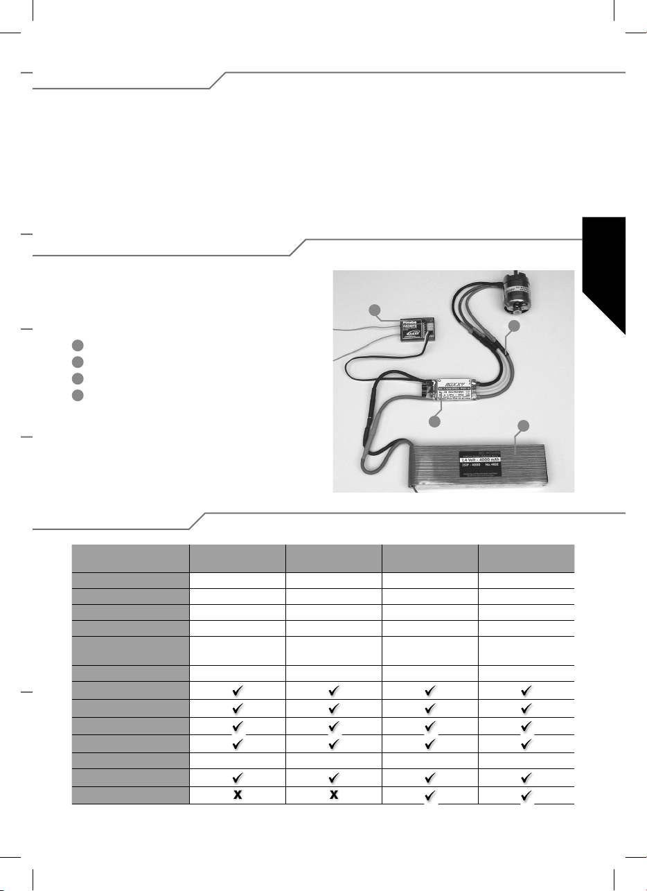
2. Connections, special features
Prepare the red (positive) wire and the black (negative) wire for
connection to the drive battery by attaching a suitable connector
system. Insulate each individual soldered joint with a heatshrink sleeve.
1
Receiver
2
Motor connection
3
Motor controller
4
Drive battery
You can take unwanted equipment to your nearest local authority waste collection point or recycling centre. There the
equipment will be disposed of correctly and at no cost to you.
By returning your unwanted equipment you can make an
important contribution to the protection of the environment!
1
2
3
4
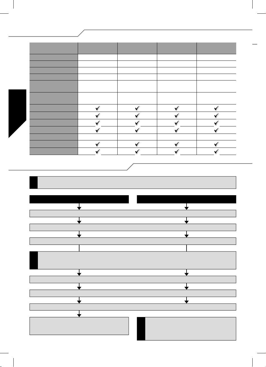
3. Speci cation
BL 908
No. 31 8627
Load current 8 A 18 A 30 A 30 A
Peak load 12 A 22 A 35 A 35 A
Dimensions (mm) 35 x 22 x 7 38 x 22 x 7 49 x 25 x 10 49 x 25 x 10
Weight (g) 15 g 25 g 29 g 29 g
Cell number 6...12 NC/NiMh
2...4 LiPo
BEC 5,5 Volt max. 2 A 5,5 Volt max. 2 A 5,5 Volt max. 2 A 5,5 Volt max.2 A
SPS
Rx-Filter
PCO
POR
hec 32 kHz 32 kHz 32 kHz 32 kHz
TP
Cool Power FET
BL 918
No. 31 8628
6...12 NC/NiMh
2...4 LiPo
BL 930
No. 31 8629
6...12 NC/NiMh
2...4 LiPo
BL 930-6
No. 31 8630
6...18 NC/NiMh
2...6 LiPo
11
Page 12
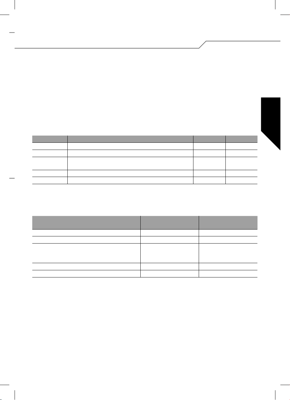
3. Speci cation
BL 940-6
Nr. 31 8631
Load current 40 A 50 A 60 A 100 A
Peak load 50 A 60 A 70 A 110 A
Dimensions (mm) 66 x 25 x 10 66 x 25 x 10 66 x 25 x 10 76 x 26 x 13
Weight (g) 47 g 49 g 49 g 67 g
Cell number 6...18 NC/NiMh
BEC 5,5 Volt
SPS
Rx-Filter
PCO
POR
hec 32 kHz 32 kHz 32 kHz 32 kHz
TP
Cool Power FET
2...6 LiPo
max. 3 A/kurz. 5 A
BL 950-6
Nr. 31 8632
6...18 NC/NiMh
2...6 LiPo
5,5 Volt
max. 3 A/kurz 5 A
BL 960-6
Nr. 31 8634
6...18 NC/NiMh
2...6 LiPo
5,5 Volt
max. 3 A/kurz. 5 A
4. Programming the stick positions
If you wish to change the model type (Parameter 4 or Parameter 5), please note that this parameter must be set before you
change the other parameters.
!
Forward, stop and reverse Forward and stop (Model type Air/Heli)
BL 9100-6
Nr. 31 8635
6...18 NC/NiMh
2...6 LiPo
5,5 Volt
max. 3 A/kurz. 5 A
1. Connect the speed controller as shown in the wiring diagram (but don’t connect the drive battery).
2. Switch the transmitter on, and move the throttle stick to the “forward” position.
3. Connect the drive battery to the speed controller.
If the LED lights up after point 2, you must reverse the throttle channel using the transmitter’s SERVO REVERSE facility.
Disconnect the drive battery from the speed controller, then start again at point 1. The “forward” position of the throttle stick
!
most be at or close to its mechanical end-stop.
4. The controller emits a brief series of beeps to confirm connection.
5. After about ten seconds a double series of beeps confirms that it has detected the “stick forward” position.
6. Move the throttle stick to the “stop” position. A brief series of beeps confirms that the controller has detected the “stop” position.
7. Move the throttle stick to the “reverse” position; a triple
series of beeps confirms that the controller has detected
the “reverse” position.
The throttle stick positions “forward” and “stop” for
“forward only” controllers are programmed in the same
manner as far as point 6. The procedure is con rmed
!
with a triple series of beeps.
12
Page 13
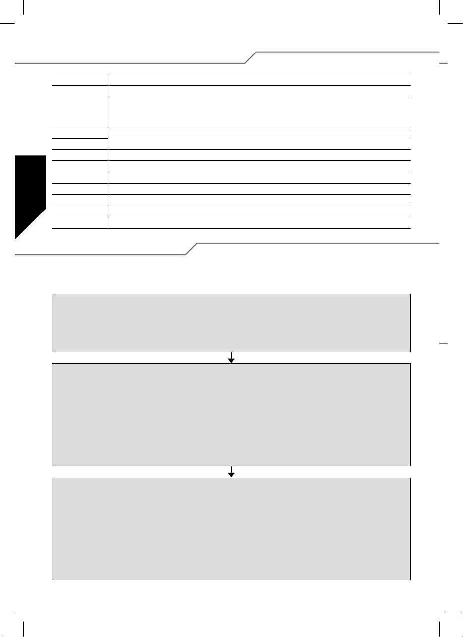
5. Programming the speed controller parameters without
using the Programmer
There are ve programmable parameters.
This is the procedure for entering programming mode:
1. Connect the speed controller as shown in the wiring
diagram (but don’t connect the drive battery).
2. Switch the transmitter on, and move the throttle stick to
the “forward” position.
3. Connect the drive battery to the speed controller.
4. The controller emits a brief series of beeps to con rm
connection.
5. After about ten seconds you will hear a double series of
beeps, followed by a triple series of beeps after a further
three seconds.
Parameter type Beep LED
Parameter 1 Battery type 1 x 1 x
Parameter 2 Direction of motor rotation 2 x 2 x
Parameter 3 - Brake ON/OFF (AIR)
- Brake ON/OFF (HELI)
Parameter 4 Model type AIR/HELI 4 x 4 x
Parameter 5 Model type BOAT/CAR 5 x 5 x
To change the parameter you must rst move the throttle
stick from the “forward” position to the “stop” position, and
leave the throttle stick in the “stop” position for at least three
seconds.
Parameter type LED ON
Battery type
Direction of rotation
Brake (AIR)
Governor (HELI)
Reverse (CAR, BOAT)
Model type (AIR/HELI)
Model type (BOAT/CAR)
The change is stored by moving the throttle stick from the
“stop” position to the “forward” position.
The speed controller now emits a continuous series of single
beeps and LED ashes to con rm that Parameter 1 has been
selected.
The parameter to be programmed is selected using the following sequence of throttle stick positions: move the throttle
stick brie y from the “forward” position to the “stop” position
then back to the “forward” position again. The controller now
emits continuous double beeps and LED ashes to con rm
that Parameter 2 has been selected. Repeat the sequence of
throttle stick movements described above in order to select
Parameters 3, 4 and 5.
3 x 3 x
The actual parameter is altered by moving the throttle stick
rapidly from the “stop” position to the “forward” position and
back.
LED ashes
Beep every 2 Sec.
LiPo NiCD/NiMH
Normal Reverse
OFF
OFF
OFF
AIR HELI
BOAT CAR
The nal step is to disconnect the drive battery; this concludes
the process and adopts the programmed settings. The speed
controller is now programmed, and is ready for use.
Beep every 0,5 Sec.
ON
ON
ON
13
Page 14
5.1. Characteristics, protective functions
BEC Integral receiver power supply.
POR Power-on guard, prevents the motor starting accidentally.
PCO Low voltage cut-off. The speed controller switches the motor off in good time when the battery is nearly
hec High pulse frequency for ne control of motor speed; also avoids premature magnet degradation.
SPS Super Programming System
Cool Power FET New generation of transistors
WP Splashproof construction (Water Protect)
Hec High motor frequency
Opto Galvanic separation between motor interference and receiver.
RX-Filter Switches the speed controller off if the transmitter signal is absent or invalid.
TOP Double overload protection (Thermal Overload Protection)
TP Thermal fuse (Thermal Protection)
discharged, in order to reserve suf cient battery capacity for controlling the model, and in order to avoid
deep-discharging the drive battery (optionally for NC/NiMH or LiPo battery).
5.2. Programming example
The following example elucidates the method of setting up the speed controller to match individual stick positions,
followed by the programming of the model type: AIR and brake ON.
Programming the stick positions
1. Switch the transmitter on, and move the throttle stick to the “forward” position.
2. Connect the drive battery to the speed controller (unit emits a brief beep).
3. After about ten seconds a double series of beeps confirms that it has detected the “stick forward” position.
4. Move the throttle stick to the “stop” position. A brief series of beeps confirms that the controller has detected the “stop” position.
5. Disconnect the drive battery from the speed controller.
Programming the controller parameters
1. Switch the transmitter on, and move the throttle stick to the “forward” position.
2. Connect the drive battery to the speed controller (unit emits a brief beep).
3.
After about ten seconds you will hear a double series of beeps, followed by a triple series of beeps after a further three seconds.
4. The controller is now in programming mode for Parameter 1 (continuous single beeps and LED flashes).
5. Select Parameter 4 by moving the throttle stick four times from the “forward” position to the “stop” position and back to the
“forward” position again (continuous quadruple beeps and LED flashes).
6. To change the parameter you must first move the throttle stick from the “forward” position to the “stop” position, leaving the
throttle stick at the “stop” position for at least three seconds.
7. Select the “Air” mode (beep sounds/LED lights up every two seconds).
8. The change is stored by moving the throttle stick from the “stop” position to the “forward” position.
Setting Air Brake On
1. When you have stored the setting as described above, the speed controller returns to parameter select: Parameter 4.
2. Select Parameter 3 by moving the throttle stick four times from the “forward” position to the “stop” position and back to the
“forward” position again (continuous triple beeps and LED flashes).
3. To change the parameter you must first move the throttle stick from the “forward” position to the “stop” position, leaving the
throttle stick at the “stop” position for at least three seconds.
4. The controller now displays the currently set brake function: Air Brake ON (beep sounds / LED flashes every 0.5 seconds) or
Air Brake OFF (beep sounds/LED lights up every two seconds). If you wish to change the parameter, move the throttle stick
rapidly from the “stop” position to the “forward” position and back.
5. The change is stored by moving the throttle stick from the “stop” position to the “forward” position.
6. Disconnect the speed controller from the drive battery.
14
Page 15
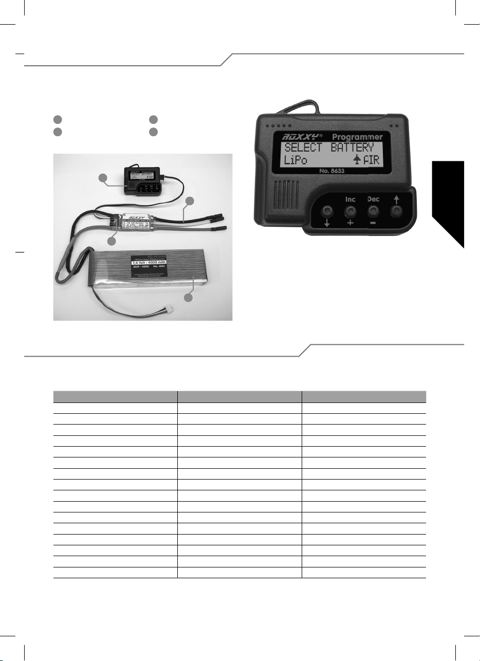
6. Settings with the programmer
The Programmer, No. 31 8633, is designed to make programming the speed controller easier; it also allows more speci c
programming to suit particular models. This compact unit is easy to handle, and provides a fast, reliable means of programming
using the integral LCD screen.
1
Programmer
2
Motor connection
1
3
3
Motor controller
4
Drive battery
2
Navigating using the Programmer
The Programmer could hardly be easier to use: the outer arrow buttons are used to move up or down in order to select
the programming modes of your choice. You can also use the
4
arrow buttons to select the model type by holding both buttons
pressed in. The purpose of the two centre buttons DEC (–) and
INC (+) is to select and/or change settings.
6.1. Overview of programming facilities
With a few exceptions, all the programming points are laid out in the same way. To help you understand the arrangement, all the
values are listed in the table printed below.
Helicopter Boat/Car Aircraft
Select Battery Select Battery Select Battery
Cut Off Voltage Cut Off Voltage Cut Off Voltage
Cut Off Type Cut Off Type Cut Off Type
Motor Direction Motor Direction Motor Direction
Advance Timing Advance Timing Advance Timing
Acceleration Acceleration Acceleration
Start Power Start Power Start Power
Response of Governor Reverse Function Air Brake Type
Governor On/ Off Motor pole Num Airbrake On/Off
Motor pole Num Gear Ratio Motor pole Num
Gear Ratio Max. RPM Gear Ratio
Max. RPM Average RPM Max. RPM
Average RPM Down Load Average RPM
Down Load Restore Mem. Down Load
Restore Mem. Backup Mem. Restore Mem.
Backup Mem. Backup Mem.
15
Page 16
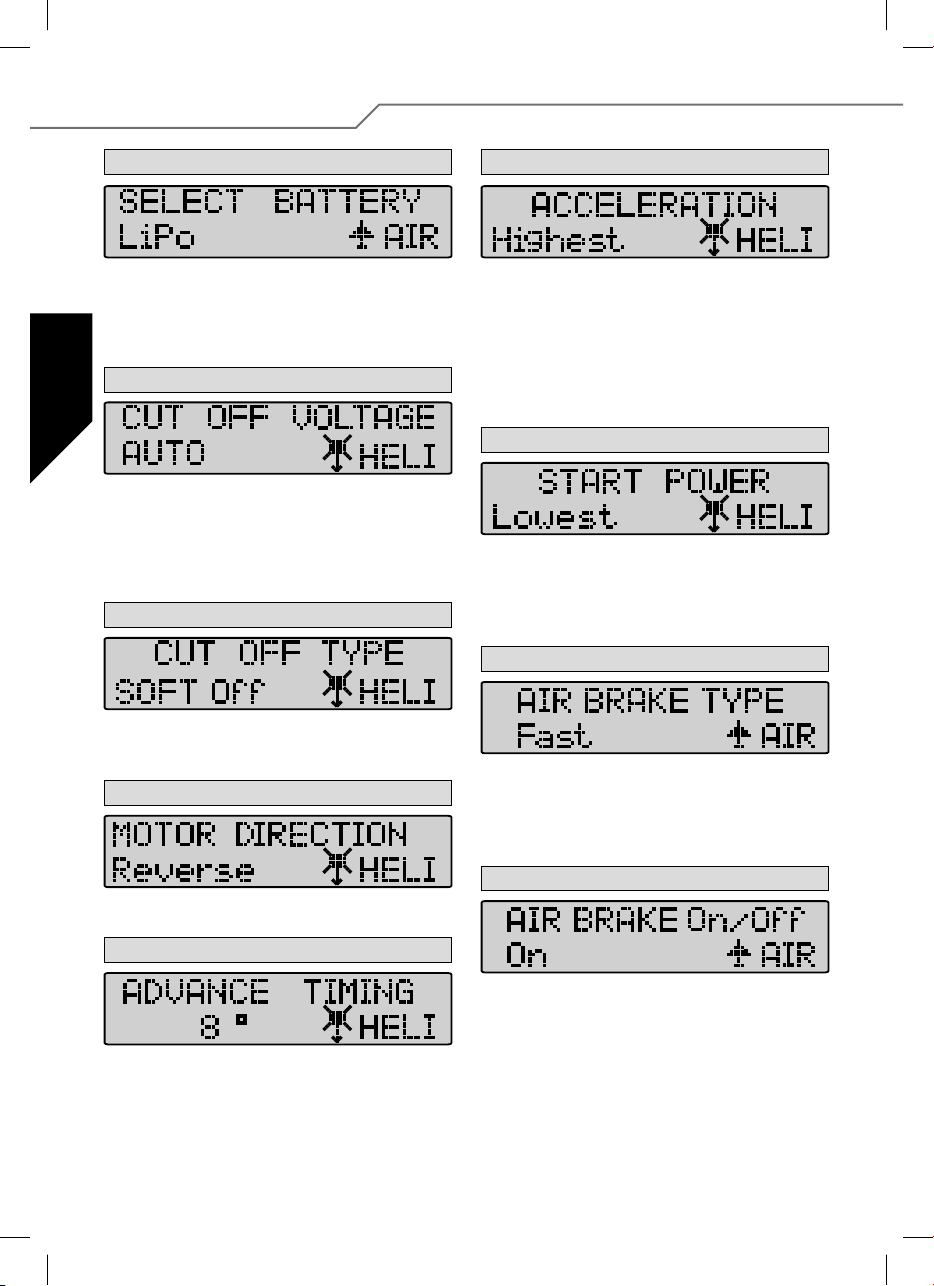
7. Programming in detail
1. Battery Type
Use the DEC or INC button to set the desired battery type.
When you have selected the new battery type you may nd
that the previously set “CUT OFF VOLTAGE” and “CUT OFF
TYPE” parameters have changed. The DEC and INC buttons
are always used to set the modes.
2. Cut Off Voltage
The Cut Off Voltage varies according to the battery type you
have set. If you have selected a LiPo battery, the speed controller switches off at 3 V per cell in Auto mode; if you have
selected a NiCd pack, the unit switches off at 5.5 V (variable
cut-off type). However, you can set the value yourself using the
DEC and INC buttons; the range extends from 4.5 V to 33.0 V.
3. Cut Off Type
In Cut Off Type mode you can select the cut-off method when
battery voltage falls to the set threshold. The options are “Soft
Off” or “Hard Off”. Use the DEC and INC buttons to set the modes.
4. Motor Direction
In Motor Direction mode you can select the direction of rotation
of your motor: the two options are normal and reversed.
5. Advance Timing
6. Acceleration
In Acceleration mode you can set how fast the controller runs
up to maximum speed. This is important if the throttle function
is assigned to a switch, as it determines the delay, i.e. the
speed with which the motor ramps up to “full-throttle”.
Example: Lowest acceleration or Highest acceleration.
Variable parameters:
Lowest / Low / Normal / High / Highest, set using the DEC
and INC buttons.
7. Start Power
In the Start Power menu you can set the level of power (torque)
which the motor produces initially, i.e. from a stand-still. If you
are using the controller in a model helicopter, the value should
be small in order to avoid premature gear wear. The available
values are Lowest / Low / Normal / High / Highest.
8. Air Brake Type
In Air mode (model aircraft) it is possible to adjust the effect
of the motor brake, and thereby determine whether the motor
comes to a halt gently (soft) or abruptly (hard). The available
options are Slow / Normal / Fast, and can be selected using
the DEC and INC buttons.
9. Air Brake On/Off - Air mode only
Advance Timing is an alternative term for motor timing. This
mode alters the advance of the rotational eld, which has a
similar effect to “advancing the ignition point”. In general terms
a setting of 8° is suitable for most motors. If you wish to use a
special set-up for your motor, we recommend the following ranges
of values: 0° to 10° for in-runner motors, and 15° to 25° for
out-runner motors.
16
This menu point is used for switching the motor brake on or off.
Page 17
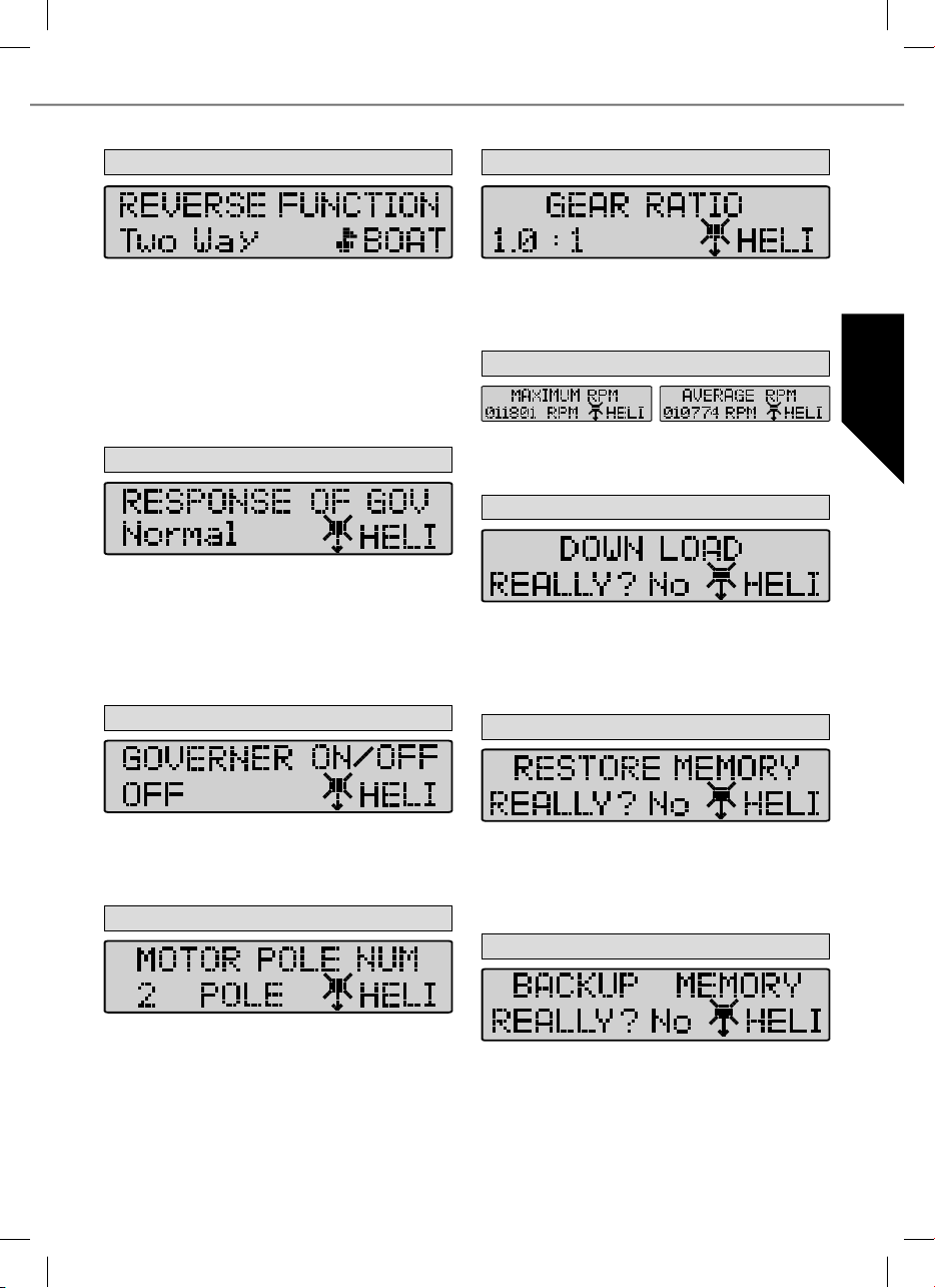
10. Reverse function (Boat and Car modes only)
14. Gear Ratio
In Boat or Car mode the Reverse function is used for selecting whether the motor works only in one direction of rotation, or in forward and reverse. In “One Way” mode (only
one direction of rotation) the motor’s direction of rotation can
also be selected: the two options are forward and reverse. In
“Two Way” mode the speed controller is set up for forward /
reverse operation.
Caution: changing the direction or motor rotation may cause
the cancellation of other settings.
11. Governor Response - Helicopter mode only
This mode is used for setting the characteristics of the speed
controller in speed governor (regulator) mode. The available
options are Slowest / Slow / Normal / Fast / Fastest.
Caution: the faster the value you select, the higher the current
drawn from the battery. We recommend that you select a fairly
low setting in order to avoid premature damage to the speed
controller and/or the ight battery.
12. Governor On / Off - Helicopter mode only
This mode is used for switching speed governor (regulator)
operation on and off. Governor mode stabilises the pre-set
rotational speed and keeps it virtually constant. The options
are: “On” mode for stabilised, or “Off” mode for non-stabilised.
13. Motor Pole Number
This mode allows you to enter the individual gearbox ratio you
are using. The value for rotational speed indication is calculated using the number of motor poles and the gearbox reduction
ratio. The available range of values is from 1.0 : 1 to 25.0 : 1.
15. Max. RPM & Average RPM
This mode shows you the maximum and average rotational
speeds recorded during the last ight, taking into account the
values set under Points 14 and 15.
16. Down Load
Download mode is used for writing (transferring) set values to
the speed controller. Press the INC button to start the process,
and the Programmer then beeps once every second until the
procedure is complete. If you wish to interrupt the process,
simply press the DEC button.
17. Restore Memory
Restore Memory is used to access values which have been
stored in the Programmer’s own memory. Press the INC button
to start the process, and the Programmer then beeps once
every second until the procedure is complete. If you wish to
interrupt the process, simply press the DEC button.
18. Backup Memory
In Motor Pole Number mode you can enter the number of
poles in your motor. This value is important for indicating the
exact rotational speed. The available range extends from 2 to
36 poles.
Backup Memory mode allows you to store permanently the
selected values in the Programmer’s integral memory. Press
the INC button to start the process, and the Programmer then
beeps once every second until the procedure is complete. The
values set on the speed controller itself are not affected by
this action. If you wish to interrupt the process, simply press
the DEC button.
17
Page 18

Contenu
1. Introduction ........................................................... 18
1.1. Consignes de sécurite ............................................ 18
1.2. Garantie et exclusion de responsabilité .................... 18
1.3. Déclaration de conformité CE ................................. 18
1.4. Elimination ............................................................. 19
2. Branchement et particularités ................................. 19
3. Caractéristiques techniques .................................... 19
4. Programmation de la position des manches ............. 20
5. Programmation des paramètres du variateur en
l’absence d’appareil de programmation ................... 21
5.1. Caractéristiques et fonctions de protection .............. 22
5.2. Exemple de programmation .................................... 22
6. Réglages avec appareil de programmation ............... 23
6.1. Vue d’ensemble des possibilités de programmation .. 23
7. Détails conceernant la programmation ..................... 24
1. Introduction
Série de petits variateurs légers béné ciant de la nouvelle technologie Cool Power FET ce qui les rend parfaitement performants
tout en leur procurant une large palette de mises en oeuvre : modèles d’avions, de bateaux, d’autos et d’hélicoptères. Les variateurs sont particulièrement conçus pour les moteurs sans balais de la série ROXXY mais également pour d’autres moteurs sans
balais.
1.1. Consignes de sécurite
- Observer les caractéristiques techniques du variateur.
- Respecter la polarité de tous les brins.
- Éviter absolument les courts-circuits.
-
Installer ou emballer le variateur de telle sorte qu‘il ne puisse
entrer en contact avec de la graisse, de l‘huile ou de l‘eau.
- Etablir une circulation d‘air suffisante.
- Ne jamais engager les mains dans des éléments en
rotation - danger de blessure.
- Fixer les moteurs en toute sécurité.
1.2. Garantie et exclusion de responsabilité
La société MULTIPLEX Modellsport GmbH & Co.KG décline toute
responsabilité en cas de pertes, dommages ou frais résultant de
l’utilisation et du fonctionnement incorrects, ou s’y rapportant de
quelque façon que ce soit. Dans la mesure où la loi le permet,
l’obligation de la société MULTIPLEX Modellsport GmbH & Co.KG
verser des dommages et intérêts, pour quelque raison juridique
ce soit, est limitée à la valeur facturée de la quantité de marchandises
de la société MULTIPLEX Modellsport GmbH & Co.KG, qui participe
directement à l’événement occasionnant les dommages. Cette
disposition ne s’applique pas si, en vertu de dispositions légales
contraignantes, la société MULTIPLEX Modellsport GmbH & Co.KG
est tenue d’assumer sans limitation la responsabilité en cas de
préméditation ou de négligence grave.
Nous accordons une garantie sur nos produits conformément aux
dispositions légales et réglementaires en vigueur. Pour tout recours
en garantie, adressez-vous au revendeur à qui vous avez acheté le
produit. Nous accordons une garantie sur nos produits conformément aux dispositions légales et réglementaires en vigueur.
Pour tout recours en garantie, adressez-vous au revendeur à qui
vous avez acheté le produit.
· Utilisation non conforme à l’usage prévu
· Entretien incorrect, retardé, annulé ou effectué par un
de
organisme non agréé
que
· Raccordements incorrects
· Utilisation d’accessoires autres que les accessoires
MULTIPLEX originaux
· Modi cations/réparations exécutées par une tierce partie (ni
MULTIPLEX ni un service de maintenance autorisé par MULTIPLEX)
· Dommages accidentels ou intentionnels
· Défauts résultant d’une usure normale
· Utilisation non conforme aux spéci cations techniques ou
associée à des composants d’autres fabricants
MULTIPLEX Modellsport GmbH & Co.KG
Westliche Gewerbestrasse 1 · D-75015 Bretten-Gölshausen
Multiplex/HiTEC Service: +49 (0) 7252 - 5 80 93 33
1.3. Déclaration de conformité CE
Le produit cité ci-dessus est conforme par rapport aux impératifs des directives harmonisées de l’union euro-péenne. De ce
fait vous possédez un produit qui, de par sa construction, respecte la restriction de sécurités en vigueurs au niveau de l’union
européenne concernant l’utilisation sécurisée des appa-reils électroniques. Vous pouvez demander la déclaration de conformité
de votre modèle auprès de la société MULTIPLEX Modellsport GmbH & Co.KG.
18
Page 19
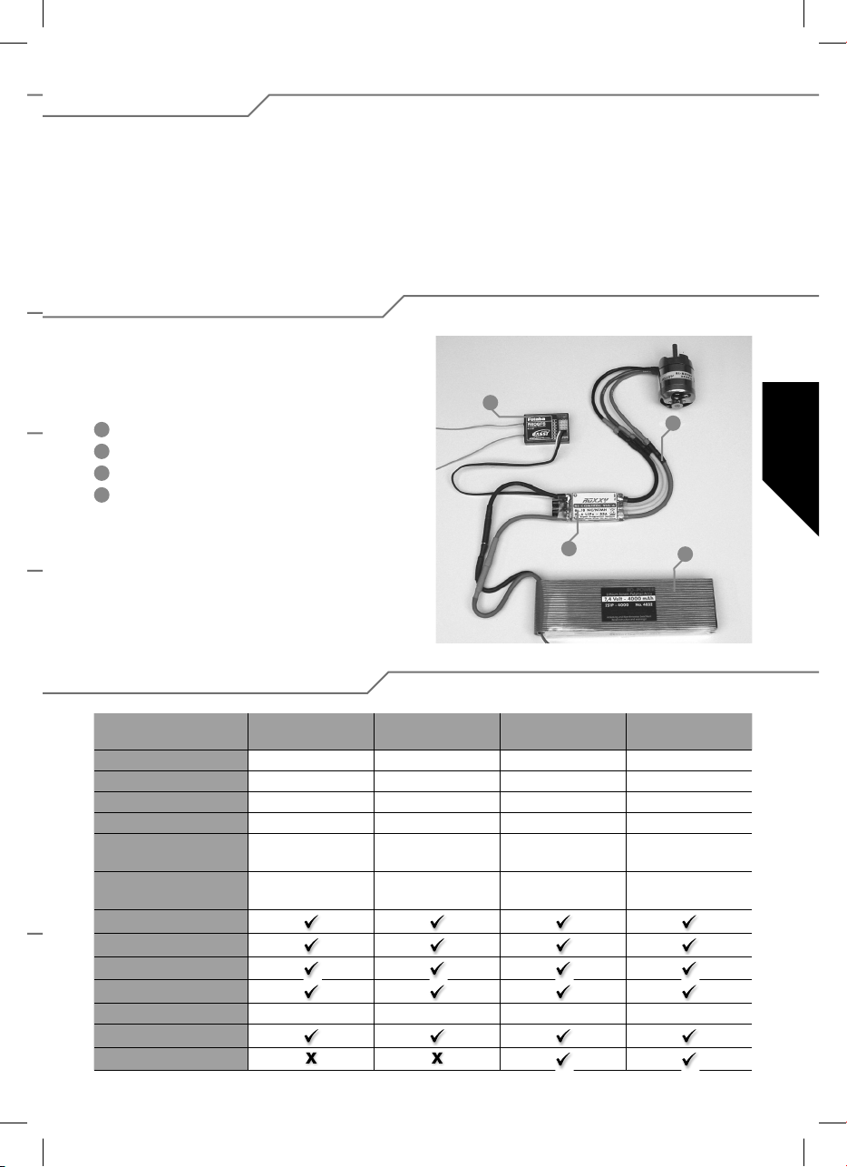
1.4. Elimination
Le symbole de la poubelle barrée sur le produit indique qu’il ne
doit pas être éliminé avec les autres ordures ménagères, mais
via un système d‘élimination adapté.
Dans les pays de l‘UE (Union européenne), les appareils électriques ne peuvent pas être éliminés avec les ordures ménagères ou les déchets non recyclables (WEEE - Waste of Electrical and Electronic Equipment, directive 2002/96/CE).
2. Branchement et particularités
Préparer le brin rouge (plus) et le brin noir (moins) avec un
système d’en chage approprié pour le raccordement à l’accu
d’alimentation du moteur. isoler tous les points de soudure
avec des morceaux de gaine thermorétractable.
1
Récepteur
2
Raccord moteur
3
Variateur
4
Accu de propulsion
Veuillez déposer l‘appareil usagé au point de collecte public
de votre commune ou de votre domicile (par ex. déchetterie).
L‘appareil y sera recyclé correctement et gratuitement. En
restituant votre appareil usagé, vous apportez une précieuse
contribution à la protection de l‘environnement.
1
2
3
4
3. Caractéristiques techniques
BL 908
Réf. 31 8627
Courant de charge 8 A 18 A 30 A 30 A
Brièvement 12 A 22 A 35 A 35 A
Encombrement (mm) 35 x 22 x 7 38 x 22 x 7 49 x 25 x 10 49 x 25 x 10
Poids (g) 15 g 25 g 29 g 29 g
Nombre d’éléments 6...12 NC/NiMh
2...4 LiPo
BEC 5,5 Volt max. 2 A 5,5 Volt max. 2 A 5,5 Volt max. 2 A 5,5 Volt max.2 A
SPS
Rx-Filter
PCO
POR
hec 32 kHz 32 kHz 32 kHz 32 kHz
TP
Cool Power FET
BL 918
Réf. 31 8628
6...12 NC/NiMh
2...4 LiPo
BL 930
Réf. 31 8629
6...12 NC/NiMh
2...4 LiPo
BL 930-6
Réf. 31 8630
6...18 NC/NiMh
2...6 LiPo
19
Page 20
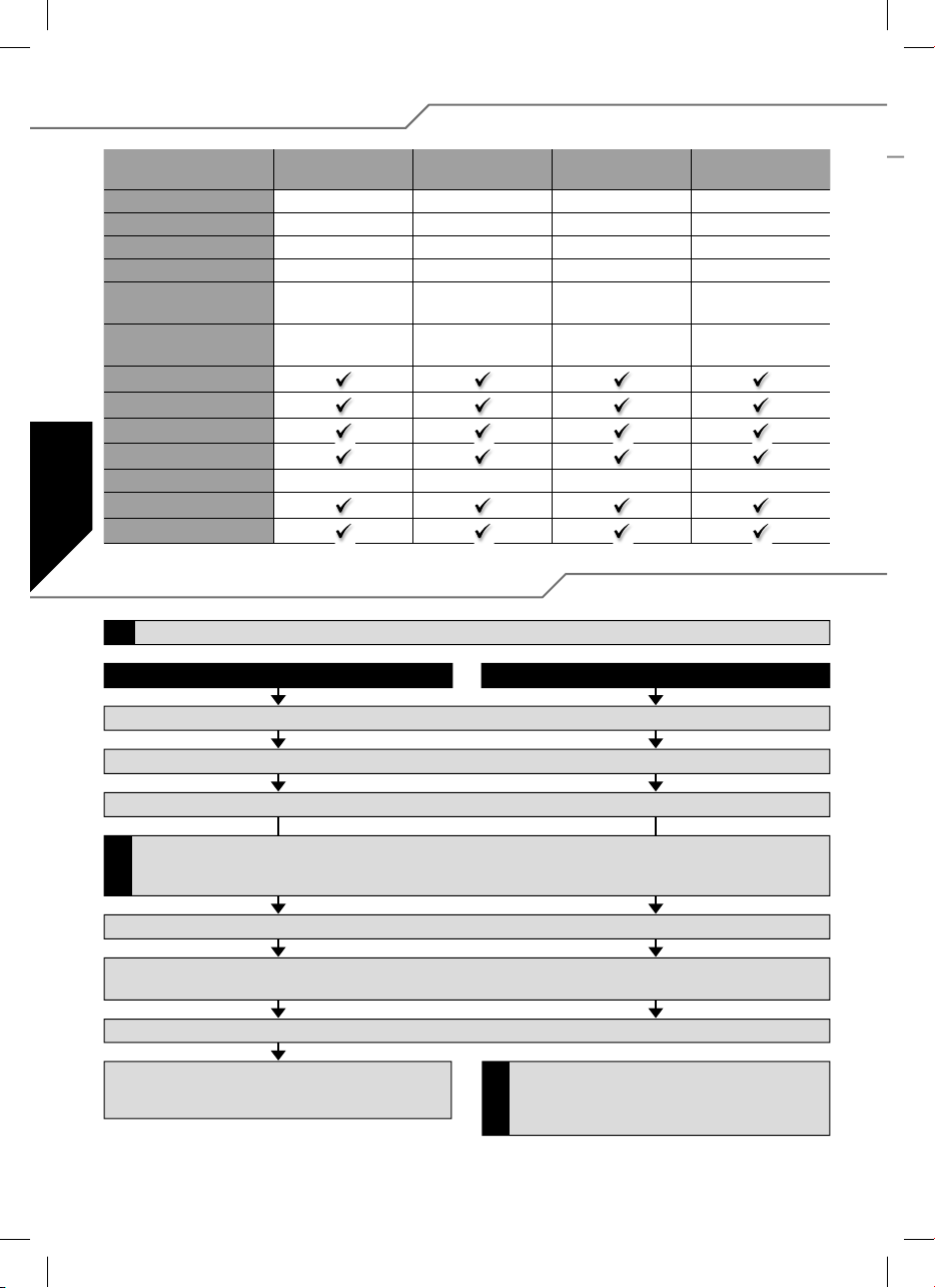
3. Caractéristiques techniques
BL 940-6
Réf. 31 8631
Courant de charge 40 A 50 A 60 A 100 A
Brièvement 50 A 60 A 70 A 110 A
Encombrement (mm) 66 x 25 x 10 66 x 25 x 10 66 x 25 x 10 76 x 26 x 13
Poids (g) 47 g 49 g 49 g 67 g
Nombre d’éléments 6...18 NC/NiMh
BEC 5,5 Volt
SPS
Rx-Filter
PCO
POR
hec 32 kHz 32 kHz 32 kHz 32 kHz
TP
Cool Power FET
2...6 LiPo
max. 3 A/kurz. 5 A
BL 950-6
Réf. 31 8632
6...18 NC/NiMh
2...6 LiPo
5,5 Volt
max. 3 A/kurz 5 A
BL 960-6
Réf. 31 8634
6...18 NC/NiMh
2...6 LiPo
5,5 Volt
max. 3 A/kurz. 5 A
4. Programmation de la position des manches
Si vous souhaitez modi er le type de modèle (paramètre 4 ou paramètre 5), il faut établir ce paramètre avant de modi er d’autres paramètres.
!
Marche avant, arrêt et marche arrière Marche avant et arrêt (Type de modèle Air/Heli)
1. Raccorder le variateur selon les indications du schéma de connexion (à l’exception de l’alimentation en tension).
BL 9100-6
Réf. 31 8635
6...18 NC/NiMh
2...6 LiPo
5,5 Volt
max. 3 A/kurz. 5 A
2. Mettre l’émetteur en marche et amener le manche des gaz en butée avant.
3. Raccorder l’alimentation en tension au variateur.
Si à la suite de cela (Pont 2) la LED s’allume, il faut actionner l’inversion de la course du servo sur l’émetteur (SERVOREVERSE), interrompre
l’alimentation en tension vers le variateur puis reprendre la programmation (au point 1). La position marche avant du manche doit se trouver
!
dans le voisinage de la butée mécanique.
4. Le variateur con rme avec une courte séquence de sons.
5. Après 10 secondes approximativement intervient une double séquence de sons pour con rmer la programmation de la position marche avant
du manche.
6. Amener le manche des gaz dans la position arrêt, une courte séquence de sons con rme le succès de la programmation de la position arrêt.
7. Amener le manche des gaz dans la position marche arrière, une
triple séquence de sons con rme le succès de la programmation
de la position marche arrière.
La programmation de la position du manche pour la marche
avant et l’arrêt en l’absence de marche arrière intervient de la
même manière que décrit précédemment jusqu’au point 6 qui
!
est con rmé par une triple séquence de sons.
20
Page 21
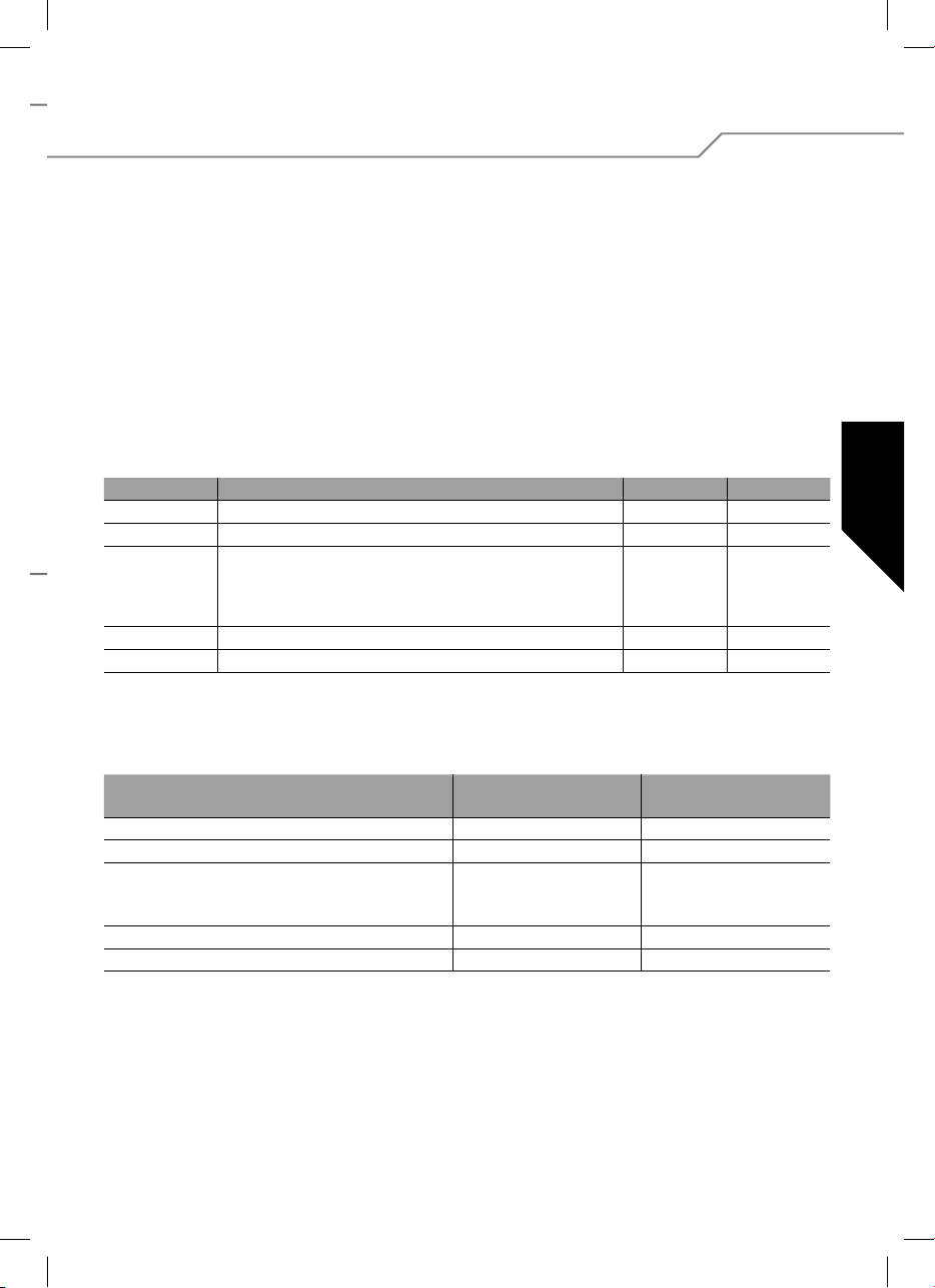
5. Programmation des paramètres du variateur en l’absence
d’appareil de programmation
Il est possible de programmer cinq paramètres.
L’accès au mode programmation intervient de la manière suivante :
1. Raccorder le variateur selon les indications du schéma de
connexion (à l’exception de l’alimentation en tension).
2. Mettre l’émetteur en marche et amener le manche des
gaz en butée avant.
3. Raccorder l’alimentation en tension au variateur.
4. Le variateur con rme avec une courte séquence de sons.
5. Après 10 secondes approximativement retentit une double
séquence de sons puis après trois secondes environ une
triple séquence de sons. Le variateur présente maintenant
la sélection du paramètre 1 par un bip continu unique et
le ash de la LED.
Type de paramètre BIP LED
Paramètre 1
Paramètre 2
Paramètre 3 Frein MARCHE/ARRET (AIR)
Paramètre 4
Paramètre 5
Pour changer de paramètre, il faut d’abord déplacer le manche
des gaz hors de ka position marche avant dans la position
arrêt et le manche des gaz doit alors demeurer au moins 3
secondes dans la position arrêt.
Type de paramètre LED allumée
Type de pile
Sens rotation
Frein (AIR)
Mode variateur (GOVERNOR, HELI)
Marche arrière (CAR, BOAT)
Type de modèle (AIR/HELI)
Type de modèle (BOAT/CAR)
Type de pile 1 x 1 x
Sens rotation 2 x 2 x
- Mode variateur (Governor)
MARCHE/ARRET (HELI)
- Marche arrière Marche/ARRET
Type de modèle AIR/HELI 4 x 4 x
Type de modèle BOAT/CAR 5 x 5 x
Le variateur présente maintenant la sélection du paramètre 1
par un bip continu unique et le ash de la LED.
La sélection des paramètres à programmer intervient à l’aide
de la séquence suivant des mouvements du manche des gaz :
changement bref du manche des gaz de la position marche
avant dans la position arrêt et retour dans la position marche
avant. Le variateur présente maintenant la sélection du paramètre 2 par un bip continu double et le clignotement de la
LED. Pour la sélection des paramètres 3, 4 et 5, il faut avoir
recours de manière répétée à la séquence du manche des gaz
décrite ci-dessus.
La modi cation du paramètre proprement dit intervient par un
changement rapide du manche des gaz hors de la position arrêt dans la position marche avant puis retour dans la position
marche avant.
bip toutes les 2 s
LiPo NiCD/NiMH
normal Inversion (Reverse)
ÉTEINTE
ÉTEINTE
ÉTEINTE
AIR HELI
BATEAU AUTO
3 x 3 x
LED clignote
bip toutes les 0,5 s
MARCHE
MARCHE
MARCHE
La sauvegarde de la modi cation intervient par un passage du
manche de gaz de la position arrêt à la position marche avant.
La n et le transfert des réglages établis pour la programmation sont sauvegardés en coupant l’alimentation en tension. Le
variateur est programmé et en ordre de marche.
21
Page 22
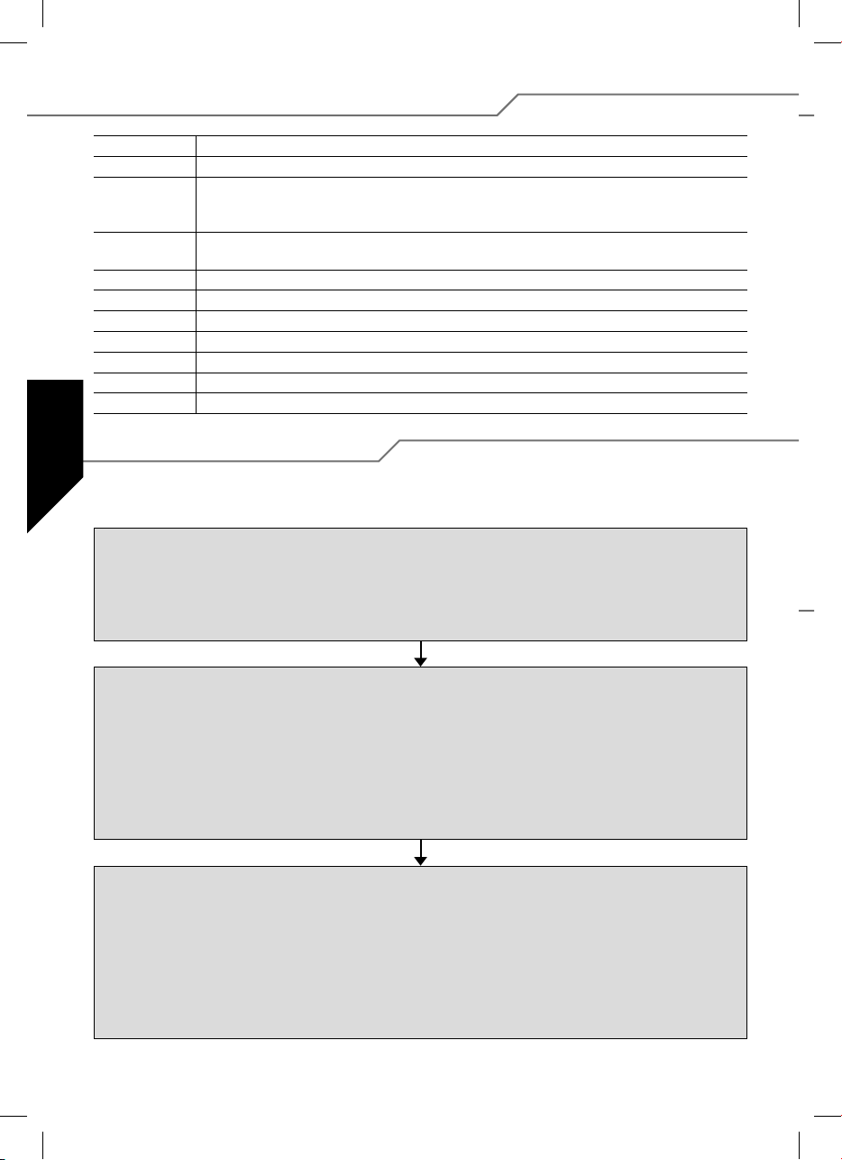
5.1. Caractéristiques et fonctions de protection
BEC Courant du récepteur alimentation.
POR Protection démarrage, évite le démarrage intempestif du moteur.
PCO Coupure en présence d‘une sous-tension, lorsque l‘accu est pratiquement vide, le moteur est coupé suf -
samment tôt pour préserver suf samment de capacité pour la commande et éviter toute décharge exces-
sive de l‘accu (facultativement pour éléments Cd-NI/NiMH ou accus Lipoly).
hec Haute fréquence d‘impulsion pour un asservissement sensible du moteur et pour éviter de surcharger
l‘aimant.
API Super système de programmation (Super Programming System).
Cool Power FET Coupe le variateur en présence de signaux perturbés ou manquants en provenance de l’émetteur.
WP Protégé contre les projections d’eau (Water Protect).
Opto Séparation galvanique entre les parasites produits par le moteur et le récepteur.
Filtre RX Coupe le variateur en présence de signaux perturbés ou manquants en provenance de l’émetteur.
TOP Double protection contre les surcharges ( Thermal Overload Protection).
TP Protection contre les surcharges thermiques (Thermal Protection).
5.2. Exemple de programmation
Dans l’exemple suivant est expliquée l’adaptation du variateur à la position individuelle du manche puis la programmation du type de modèle : AIR et frein MARCHE.
Programmation de la position des manches
1. Mettre l’émetteur en marche et amener le manche des gaz dans la position marche avant souhaitée.
2. Raccorder l’alimentation en tension au variateur (une courte séquence de sons retentit).
3. Après 10 secondes approximativement intervient une double séquence de sons pour con rmer la programmation de la position marche
avant du manche.
4. Amener le manche des gaz dans la position arrêt, une courte séquence de sons con rme le succès de la programmation de la position arrêt.
5. Interrompre l‘alimentation électrique.
Programmation des paramètres du variateur
1. Mettre l’émetteur en marche et amener le manche des gaz en butée avant.
2. Raccorder l’alimentation en tension au variateur (une courte séquence de sons retentit).
3. Après 10 secondes approximativement retentit une double séquence de sons puis après trois secondes environ une triple séquence de sons.
4. Maintenant le variateur se trouve en mode programmation paramètre 1 (bip continu unique et clignotement de la LED).
5. En changeant quatre fois la position du manche des gaz de la position marche avant à la position arrêt puis retour dans la position marche
avant, on accède au paramètre 4 (quadruple bip continu et quadruple clignotement de la LED).
6. Pour passer à un autre paramètre, il faut d’abord déplacer le manche des gaz de la position marche avant à la position arrêt.
Le manche des gaz doit demeurer au moins 3 secondes dans la position arrêt.
7. Sélectionner le mode Air (la LED est allumée/bip toutes les deux secondes).
8. La sauvegarde intervient par un passage du manche de gaz de la position arrêt à la position marche avant.
Régler Air Brake On (Air frein marche)
1. Après la sauvegarde décrite ci-dessus, le variateur se retrouve dans la sélection du paramètre 4.
2. En changeant quatre fois la position du manche des gaz de la position marche avant à la position arrêt puis retour dans la position marche
avant, on accède au paramètre 3 (triple bip continu et triple clignotement de la LED).
3. Pour passer à un autre paramètre, il faut d’abord déplacer le manche des gaz de la position marche avant à la position arrêt.
Le manche des gaz doit demeurer au moins 3 secondes dans la position arrêt.
4. Maintenant apparaît la fonction actuellement établie du frein. Air Brake ON (LED clignote/Bip toutes les 5 s) ou Air Brake OFF (LED allumée/
Bip toutes les 2 s). Si nécessaire, modi er le paramètre en passant rapidement avec le manche des gaz de la position arrêt à la position
marche avant puis retour.
5. La sauvegarde de la modi cation intervient par un passage du manche de gaz de la position arrêt à la position marche avant.
6. Interrompre l‘alimentation électrique
22
Page 23
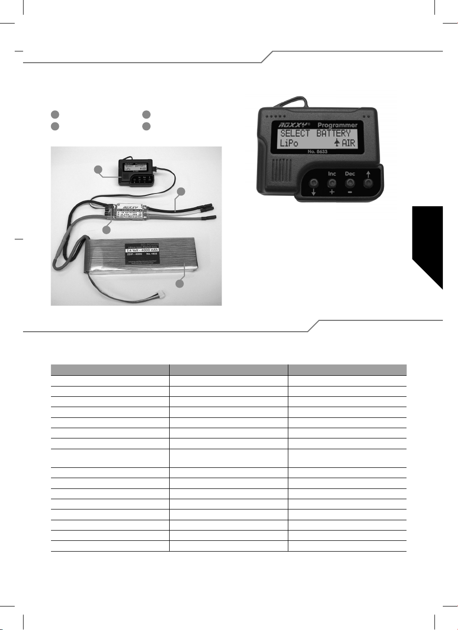
6. Réglages avec appareil de programmation
Pour pouvoir programmer le variateur plus simplement et plus spéci quement en fonction du modèle, utilisez l’appareil de
programmation, réf. 31 8633. Cette unité de conduite très claire vous permet, via un écran à cristaux liquides, de programmer
rapidement et sûrement les paramètres devant être mis au point.
1
Programmer
2
Raccord moteur
1
3
3
Variateur
4
Accu de propulsion
2
Navigation avec l’appareil de programmation
Le mise en œuvre de l’appareil de programmation est aussi
simple que possible. Avec les touches à èche extérieures
sauter soit vers le bas soit vers le haut pour accéder au mode
de programmation que vous souhaitez. Par ailleurs elles permettent de passer d’un type de modèle à l’autre lorsqu’on
4
maintien deux touches à èche enfoncées simultanément.
Les deux touches du milieu DEC (–) et INC (+), permettent de
sélectionner ou de changer un réglage.
6.1. Vue d’ensemble des possibilités de programmation
À l’exception de quelques différences minimes, les points de programmation sont agencés pour l’essentiel de la même manière.
Pour une meilleure compréhension, toutes les valeurs sont reprises dans le tableau ci-dessous.
Héli Boat/Car (bateau-auto) Air (avion)
Select Battery (type d’alimentation) Select Battery (type d’alimentation) Select Battery (type d’alimentation)
Cut Off Voltage (tension d’arrêt) Cut Off Voltage (tension d’arrêt) Cut Off Voltage (tension d’arrêt)
Cut Off Type (moteur arrêt type) Cut Off Type (moteur arrêt type) Cut Off Type (moteur arrêt type)
Motor Direction (sens de rotation du moteur) Motor Direction (sens de rotation du moteur) Motor Direction (sens de rotation du moteur)
Advance Timing (minutage moteur) Advance Timing (minutage moteur) Advance Timing (minutage moteur)
Acceleration (accélération) Acceleration (accélération Acceleration (accélération)
Start Power (demarrage puissance) Start Power (demarrage puissance) Start Power (demarrage puissance)
Response of Governor
(Caractéristique de réglage)
Governor On/Off (variateur marche/arrêt) Motor pole Num (nombre de pôles du moteur) Airbrake On/Off (frein moteur marche/arrêt)
Motor pole Num (nombre de pôles du moteur) Gear Ratio (démultiplication mécanisme) Motor pole Num (nombre de pôles du moteur)
Gear Ratio (démultiplication mécanisme) Max. RPM (af chage régime max.) Gear Ratio (démultiplication mécanisme)
Max. RPM (af chage régime max.) Average RPM (régime moyen) Max. RPM (af chage régime max.)
Average RPM (régime moyen) Down Load (écriture de données) Average RPM (régime moyen)
Down Load (écriture de données) Restore Mem. (lire chiers program.) Down Load (écriture de données)
Restore Mem. (lire chiers program.) Backup Mem. (copie de sécurité) Restore Mem. (lire chiers program.)
Backup Mem. (copie de sécurité) Backup Mem. (copie de sécurité)
Reverse Function
(function d’inversion)
Air Brake Type
(type du frein moteur)
23
Page 24
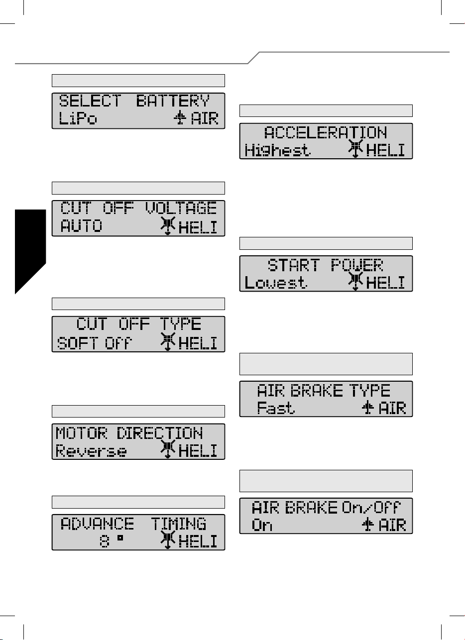
7. Détails conceernant la programmation
1. Battery Type (type d’alimentation)
Pour établir le type d’alimentation souhaité, utiliser la touche DEC ou la
touche INC. Une fois que vous avez sélectionné un nouveau type d’accu, il se peut que des paramètres préprogrammés dans les domaines
“CUT OFF VOLTAGE” et “CUT OFF TYPE” aient changé. Les modes
peuvent toujours être mis au point à l’aide des touches DEC et INC.
2. Cut Off Voltage (tension d’arrêt)
La tension de commutation (Cut Off Voltage) est fonction du type d’accu
établi. Avec un accu Lipo dans le mode automatique (Auto Mode), le
variateur commute à 3 volts par élément, toutefois avec un accu Cd-Ni
déjà à 5,5 volts (type de commutation réglable). Il est possible d’établir
soi-même une valeur à l’aide des touches DEC et INC. La gamme de
réglage va de 4,5 à 33,0 volts.
3. Cut Off Type (moteur arrêt type)
En mode moteur arrêt type (Cut Off Type) il est possible d’établir le
type de commutation en présence d’une éventuelle sous-tension. Il est
possible d’établir les modes doux (“Soft Off”) ou brusque (“Hard Off”).
Les modes peuvent là aussi être mis au point à l’aide des touches
DEC et INC.
8° pour la plupart des moteurs. Pour établir une mise au point spéciale
(Setup) pour votre moteur, nous vous recommandons les valeurs suivantes : 0°-10° pour les moteurs à induit.
6. Acceleration (accélération)
Sous le mode Acceleration (accélération) on établit la rapidité avec
laquelle le variateur accélère jusqu’à la valeur maximale. Ce réglage
est très important lorsque la fonction des gaz est actionnée par un
interrupteur a n d’établir le délai avec lequel la vitesse doit passer à
“plein gaz”. Exemple : Lowest/accélération minimale ou Highest/accélération maximale. Paramètres réglables : Lowest / Low / Normal /
High / Highest (très bas / bas / normal / élevé / très élevé). Mise au
point à l’aide des touches DEC et INC.
7. Start Power (démarrage puissance)
Dans le menu Start Power, établir la puissance de démarrage (couple)
avec laquelle le moteur démarre (à partir de son immobilisation). Particulièrement avec une mise en oeuvre dans un hélicoptère, il faut
sélectionner des valeurs réduites pour épargner la roue dentée. Il est
possible d’établir les réglages suivants Lowest / Low / Normal / High /
Highest (très réduit / réduit / normal / élevé / très élevé).
8. Air Brake Type (type de frein moteur) – uniquement
pour le mode avion (Air Mode) !
4. Motor Direction (sens de rotation du moteur)
Dans le mode sens de rotation du moteur (Motor Direction) il est possible de choisir entre le sens de rotation normal et le sens de rotation
inversé pour votre moteur.
5. Advance Timing (minutage moteur)
Le mode avance minutage (Advance Timing) est à considérer comme
un minutage moteur (Motor Timing). Cette mise au point permet d’induire une avance du champ magnétique rotatif permettant de provoquer un “allumage anticipé”. En règle générale, cette avance se limite à
24
Dans le mode avion (Air Mode) il est possible de régler l’ef cacité du
frein moteur et ainsi de faire en sorte que le moteur s’immobilise lentement ou rapidement (sur le champ). Il est possible de sélectionner les
mode souple – normal – brusque (Slow / Normal / Fast) à l’aide des
touches DEC et INC.
9. Air Brake On/Off (frein moteur marche/arrêt) uniquement en mode avion (Air Mode)
Dans ce point de menu, il est possible de mettre le frein moteur en
marche ou de l’arrêter.
Page 25
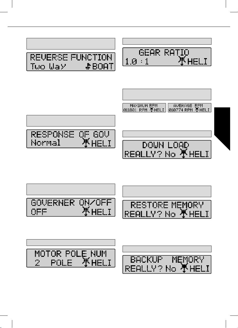
10. Fonction d’inversion (Reverse Function) (unique ment dans le mode bateau+auto (Boat+Car)) !
Avec la fonction d’inversion (Reverse Function) il est possible de choisir
dans le mode bateau (Boat) ou dans le mode auto (Car) si le moteur ne
doit travailler que dans une direction de rotation ou en marche avant /
marche arrière. Dans le mode une direction (“One Way”) on dé nit le
sens de rotation du moteur – marche avant ou marche arrière. Dans le
mode deux directions (“Two Way Modus”) le variateur est réglé pour le
mode marche avant/marche arrière.
Attention : les réglages peuvent être annulés lorsqu’on change le sens
sens de rotation du moteur (Motor Direction).
11. Response of Governor (caractéristique de régula tion) uniquement pour l’hélicoptère (Heli)
Dans ce mode il est possible d’établir la caractéristique de régulation du
variateur. Il est possible de choisir entre les domaines Slowest / Slow /
Normal / Fast / Fastest (très lent, lent, normal, rapide, très rapide).
Attention : le courant délivré par l’accu croît proportionnellement avec
la valeur de vitesse établie. Pour économiser le variateur et consommer moins et accroître l’autonomie de votre modèle sélectionner des
valeurs réduites.
12. Governor On/Off (variateur marche/arrêt) unique ment hélicoptère (Heli)
14. Gear Ratio (démultiplication mécanisme)
Ce niveau de mise au point permet se saisir la démultiplication effective
de votre mécanisme de transmission. Le nombre de l’af chage du régime est calculé à partir du nombre de pôles du moteur et de la démultiplication du mécanisme. Les valeurs réglables vont de 1,0:1 à 25,0:1.
15. Max. RPM & Average RPM (affichage du régime
maximal & moyen)
Ces modes présentent le régime maximal et le régime moyen au cours
de la dernière séance de vol, compte tenu des valeurs établies sous
les points 14 et 15.
16. Down Load (écriture de données)
Avec l’écriture (Down Load) vous chargez les valeurs établies sur le
variateur. La touche INC permet de démarrer l’application, l’appareil
de programmation produit un bip chaque seconde jusqu’à ce que
l’application est achevée. Si vous souhaitez interrompre la procédure,
appuyez sur la touche DEC.
17. Lire les données de l’appareil de programmation
(Restore Memory)
Dans ce menu on met le variateur en marche ou on l’arrête. Celui-ci
stabilise le régime programmé et le maintient quasiment constant. Le
mode MARCHE (On) pour stabilisé et le mode ARRET (Off) pour non
stabilisé.
13. Motor pole Number (nombre de pôles du moteur)
Cette rubrique nombre de pôles du moteur (Motor Pole Number) permet
de sélectionner le nombre de pôles dont est pourvu votre moteur. Cette
valeur est importante pour indiquer avec précision le régime. La valeur
qu’il est possible d’établir peut varier sur une La valeur qu’il est possible d’établir peut varier sur une fourchette de 2 à 36 pôles.
Avec la fonction Restore Memory vous ouvrez les valeur sauvegardées
sur la mémoire propre de l’appareil de programmation. La touche INC
permet de démarrer l’application, l’appareil de programmation produit
un bip chaque seconde jusqu’à ce que l’application est achevée. Si
vous souhaitez interrompre la procédure, appuyez sur la touche DEC.
18. Backup Memory (copie de sécurité)
Avec la fonction Backup Memory vous sauvegardez les valeurs programmées dans la mémoire se trouvant dans l’appareil de programmation. La touche INC permet de démarrer l’application, l’appareil de programmation produit un bip chaque seconde jusqu’à ce que l’application
est sauvegardée. Les valeurs établies sur le variateur n’en subissent
aucune in uence. Si vous souhaitez interrompre la procédure, appuyez
sur la touche DEC.
25
Page 26

Contenuto
1. Introduzione ........................................................... 26
1.1. Avvisi di sicurezza .................................................. 26
1.2. Garanzia ed esclusione di responsabilita .................. 26
1.3. Contrassegno CE ................................................... 26
1.4. Smaltimento .......................................................... 27
2. Collegamento e caratteristiche ................................ 27
3. Dati tecnici ............................................................ 27
Programmazione delle posizioni dello stick di comando
4.
.... 28
5. Programmazione dei parametri del regolatore senza
collegamento con programmatore ........................... 29
Caratteristiche del dispositivo e funzioni di protezione
5.1.
5.2. Esempio di programmazione ................................... 30
6. Impostazioni con programmatore ............................ 31
6.1. Panoramica delle programmazioni disponibili ........... 31
7. Dettagli per la programmazione ............................... 32
1. Introduzione
I dispositivi Roxxy BL Control, rappresentano una famiglia di regolatori leggeri e compatti, equipaggiati con la nuovissima tecnologia Cool Power FET. Estremamente potenti , sono utilizzabili in un’ampia gamma di modelli navali, aerei, elicotteri ed automodelli.
Particolarmente adatti in abbinamento a motori brushless della serie ROXXY, ma comunque utilizzabili anche sugli altri tipi di motori
brushless. Leggere attentamente il manuale di istruzioni prima del collegamento e dell’utilizzo del regolatore.
1.1. Avvisi di sicurezza
- Tenete conto dei dati tecnici del regolatore.
- Tenete conto della polarità dei cavi di alimentazione.
- Evitate assolutamente cortocircuiti.
Installate rispettivamente proteggete il regolatore in maniera
-
che non venga a contatto con grasso, olio oppure acqua.
- Assicuratevi che vi sia sufficiente circolazione d‘aria.
- Non cercate mai di afferrare parti in movimento: rischio di
infortuni.
- Installate i motori in maniera sicura.
Ci riserviamo il diritto di apportare modifiche tecniche.
1.2. Garanzia ed esclusione di responsabilita
La ditta MULTIPLEX Modellsport GmbH & Co.KG declina
ogni responsabilità in caso di perdite, danni o costi derivanti
dall‘utilizzo non corretto del prodotto o in qualche modo
riconducibili a esso. Se previsto dalla legge, la responsabilità
della ditta MULTIPLEX Modellsport GmbH & Co.KG in merito
alla prestazione di indennizzi si limita, indipendentemente dalla
causa dell‘indennizzo, al valore contabile dei prodotti della ditta
MULTIPLEX Modellsport GmbH & Co.KG direttamente coinvolti
nell‘evento all‘origine del danno. Questa regola non vale se
la ditta MULTIPLEX Modellsport GmbH & Co.KG è soggetta
a responsabilità illimitata in base alle disposizioni di legge
cogenti poiché ha agito con premeditazione o grave negligenza.
Offriamo garanzia per i nostri prodotti in base alle norme di
legge attualmente in vigore. Nei casi previsti dalla garanzia
è necessario rivolgersi al rivenditore presso il quale è stato
acquistato il prodotto.
Non rientrano nella garanzia i casi di malfunzionamento
riconducibili a:
· utilizzo non appropriato
· manutenzione mancata, ritardata o eseguita in modo errato
o da un centro non autorizzato
· attacchi errati
· utilizzo di accessori MULTIPLEX non originali
·
modi che o riparazioni non eseguite da MULTIPLEX o dai centri
servizi MULTIPLEX
· danni apportati inavvertitamente o intenzionalmente
· difetti derivanti da una normale usura
· utilizzo che esula dalle speci che tecniche o con
componenti di altri produttori.
MULTIPLEX Modellsport GmbH & Co.KG
Westliche Gewerbestrasse 1 · D-75015 Bretten-Gölshausen
Multiplex/HiTEC Service: +49 (0) 7252 - 5 80 93 33
.... 30
1.3. Contrassegno CE
La valutazione degli apparecchi avviene secondo le normative europee. Lei è quindi in possesso di un apparecchio che rispetta
i requisiti di costruzione e sicurezza stabiliti dall’Unione Europea. La dichiarazione di conformità per l’apparecchio può essere
richiesta alla MULTIPLEX Modellsport GmbH & Co.KG.
26
Page 27
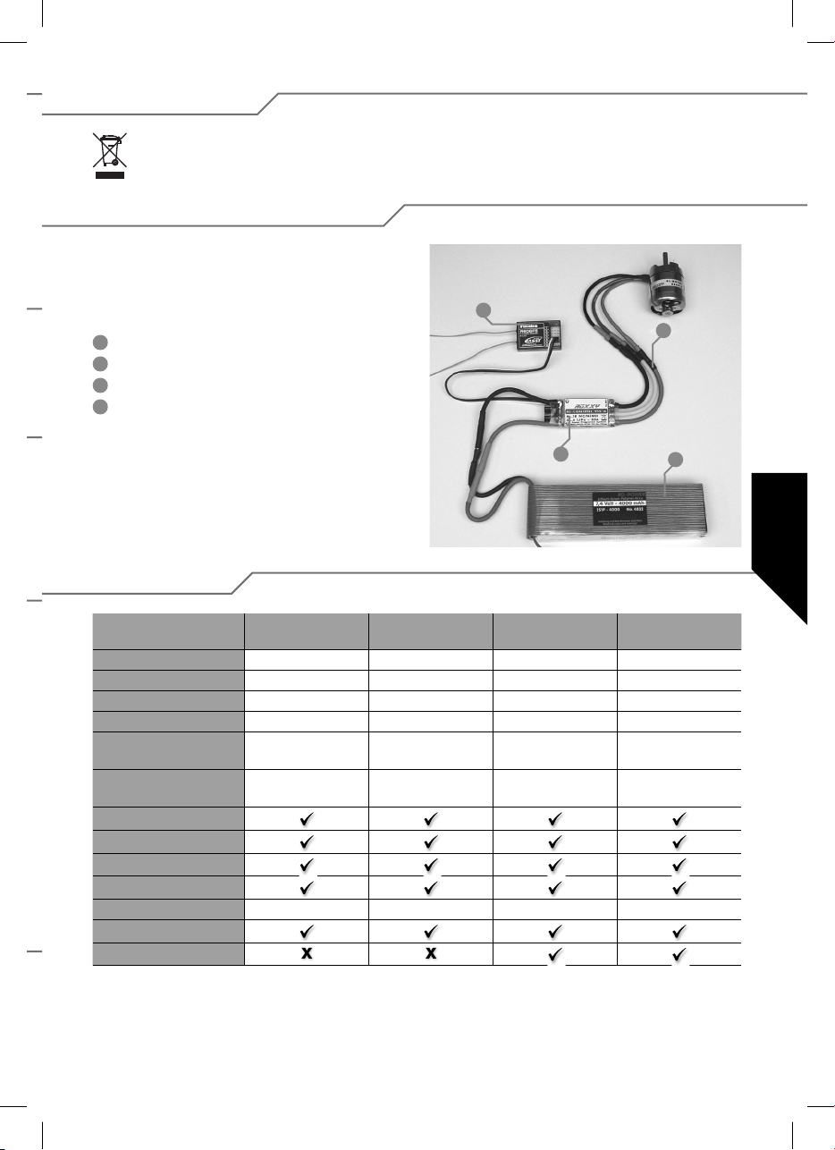
1.4. Smaltimento
Questo simbolo indica che al termine del loro utilizzo gli apparecchi elettronici devono essere smaltiti separatamente.
Smaltire l‘apparecchio presso gli appositi punti di raccolta, come i punti autorizzati dal comune. Questo vale per tutti i
Paesi dell‘Unione Europea e per tutti gli altri Paesi europei che attuano la raccolta differenziata dei ri uti.
2. Collegamento e caratteristiche
Predisporre il cavo rosso (positivo) e quello nero (negativo) al
collegamento con la batteria, equipaggiandoli con gli appositi
connettori. Isolare mediante tubo termoretraibile tutte le zone
di saldatura.
1
Ricevente
2
Collegamento con il motore
3
Regolatore
4
Batteria di alimentazione
1
2
3
4
3. Dati tecnici
BL 908
No. 31 8627
Corrente di carico 8 A 18 A 30 A 30 A
Picco max 12 A 22 A 35 A 35 A
Dimensioni (mm) 35 x 22 x 7 38 x 22 x 7 49 x 25 x 10 49 x 25 x 10
Peso (g) 15 g 25 g 29 g 29 g
Numero di celle 6...12 NC/NiMh
2...4 LiPo
BEC 5,5 Volt max. 2 A 5,5 Volt max. 2 A 5,5 Volt max. 2 A 5,5 Volt max.2 A
aps
Filtro Rx
PCO
POR
hec 32 kHz 32 kHz 32 kHz 32 kHz
TP
Cool Power FET
BL 918
No. 31 8628
6...12 NC/NiMh
2...4 LiPo
BL 930
No. 31 8629
6...12 NC/NiMh
2...4 LiPo
BL 930-6
No. 31 8630
6...18 NC/NiMh
2...6 LiPo
27
Page 28
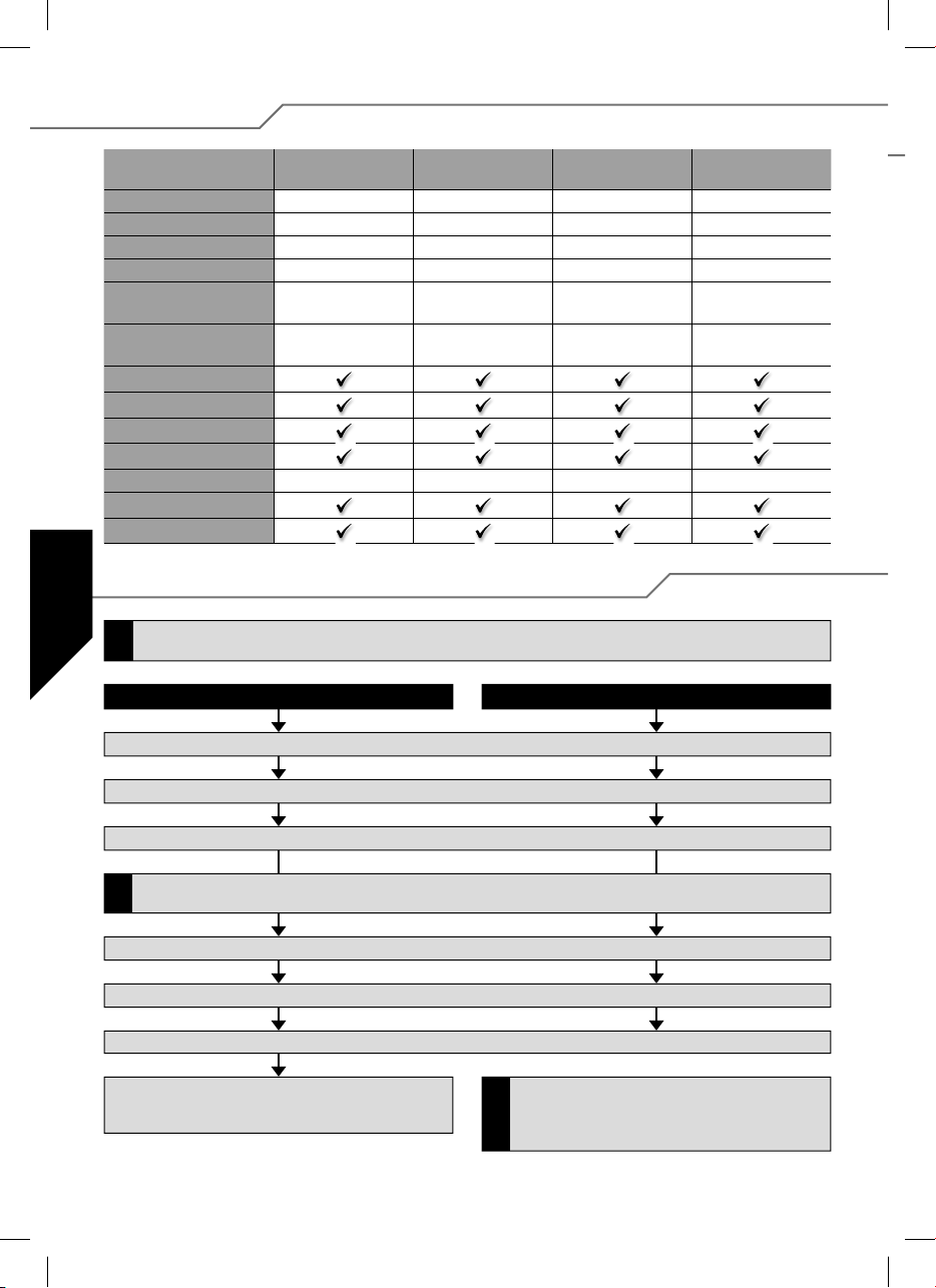
3. Dati tecnici
BL 940-6
No. 31 8631
Corrente di carico 40 A 50 A 60 A 100 A
Picco max 50 A 60 A 70 A 110 A
Dimensioni (mm) 66 x 25 x 10 66 x 25 x 10 66 x 25 x 10 76 x 26 x 13
Peso (g) 47 g 49 g 49 g 67 g
Numero di celle 6...18 NC/NiMh
2...6 LiPo
BEC 5,5 Volt
max. 3 A/kurz. 5 A
aps
Filtro Rx
PCO
POR
hec 32 kHz 32 kHz 32 kHz 32 kHz
TP
Cool Power FET
BL 950-6
No. 31 8632
6...18 NC/NiMh
2...6 LiPo
5,5 Volt
max. 3 A/kurz 5 A
BL 960-6
No. 31 8634
6...18 NC/NiMh
2...6 LiPo
5,5 Volt
max. 3 A/kurz. 5 A
4. Programmazione delle posizioni dello stick di comando
Se si intende effettuare una modi ca del tipo di modello (Parametro 4 oppure Parametro 5), è necessario eseguirla prima di modi care gli
altri parametri.
!
Atvanti, stop e indietro Avanti e stop (Tipo di modello Air/Heli)
BL 9100-6
No. 31 8635
6...18 NC/NiMh
2...6 LiPo
5,5 Volt
max. 3 A/kurz. 5 A
1. Collegare il regolatore come indicato nello schema di collegamento (eccetto l’alimentazione).
2. Accendere la trasmittente e portare lo stick di comando di gas in posizione avanti.
3. Collegare la fonte di alimentazione (batteria) con il regolatore.
Se dopo il punto 2 si illumina il LED, occorre azionare l’interruttore SERVO-REVERSE sulla trasmittente, scollegare la batteria di alimentazione
dal regolatore e ripartire dal punto 1.La posizione avanti dello stick deve risultare in prossimità del punto di ne corsa meccanico.
!
4. Il regolatore emette un breve segnale acustico di conferma.
5. Trascorsi 10 secondi ca. viene emessa una sequenza sonora doppia di conferma per l’avvenuta programmazione della posizione in avanti.
6. Portare lo stick di comando del gas in posizione “stop” ; un breve segnale acustico conferma l’avvenuta programmazione della posizione di stop.
7. Portare lo stick di comando del gas in posizione indietro; un triplice segnale acustico conferma l’avvenuta programmazione della
posizione indietro.
Per i regolatori che hanno solo la marcia avanti, la programmazione delle posizioni avanti e stop avviene analogamente
a quanto descritto in precedenza ma solo no al punto 6. Un
!
triplice segnale acustico conferma l’avvenuta impostazione.
28
Page 29
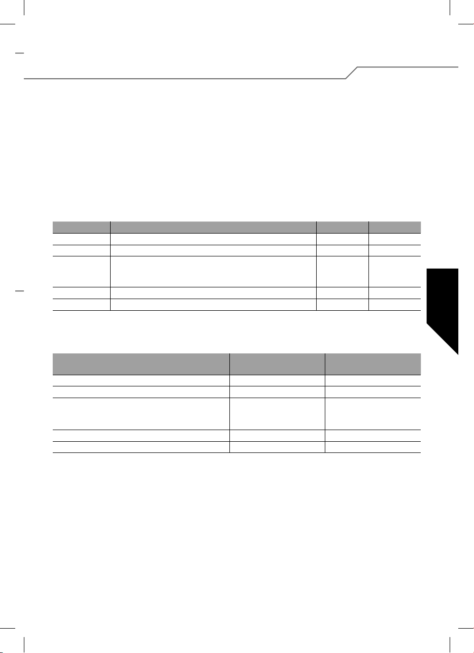
5. Programmazione dei parametri del regolatore senza
collegamento con programmatore
Risulta possibile programmare cinque parametri.
Per accedere alla modalità di programmazione procedere come
segue:
1. Collegare il regolatore come indicato nello schema di
collegamento (eccetto l’alimentazione).
2. Accendere la trasmittente e portare lo stick di comando
del gas in posizione avanti.
3. Collegare la fonte di alimentazione (batteria) con il regolatore.
4. Il regolatore emette un breve segnale acustico di conferma.
5. Trascorsi 10 secondi ca. viene emessa una sequenza
sonora doppia di conferma; dopo ulteriori 3 secondi viene
emessa una sequenza sonora tripla.
Tipo di parametro Beep LED
Parametro 1 Tipo di batteria
Parametro 2 Verso di rotazione
Parametro 3 - Freno attivato/disattivato (AIR)
- Governor ON/OFF (HELI)
- Indietro ON/OFF (CAR, BOAT)
Parametro 4 Tipo di modello AIR/HELI
Parametro 5 Tipo di modello BOAT/CAR
Per modi care il parametro è necessario spostare lo stick
del gas da posizione avanti a posizione stop e lasciarlo in tale
posizione per almeno 3 secondi.
Tipo di parametro LED ACCESO
Tipo di batteria LiPo NiCD/NiMH
Verso di rotazione Normale Reverse
Freno (AIR)
Governor (HELI)
Indietro (CAR, BOAT)
Tipo di modello (AIR/HELI) AIR HELI
Tipo di modello (BOAT/CAR) BOOT CAR
Il regolatore segnala a questo punto all’utente la possibilità di
selezione del parametro 1, attraverso il lampeggio del LED ed
un segnale acustico unico.
Per selezionare il tipo di parametro che si intende programmare, azionare lo stick di comando come segue: cambiare rapidamente la posizione dello stick di comando, portandolo da
“posizione avanti” a “posizione di stop” e di nuovo a “posizione
avanti”. Il regolatore segnala in questo istante l’avvenuta selezione del parametro 2 attraverso un “Beep” doppio continuo
ed il lampeggio del LED. Per la selezione dei parametri 3, 4 e
5 occorre ripetere la sequenza appena descritta.
1 x 1 x
2 x 2 x
3 x 3 x
4 x 4 x
5 x 5 x
La modi ca effettiva del parametro ha luogo non appena si
sposta rapidamente lo stick dalla posizione di stop alla posizione avanti e poi di nuovo di stop.
“Beep” ogni 2 s.
SPENTO
SPENTO
SPENTO
LED LAMPEGGIANTE
“Beep” ogni 0,5 s.
ACCESO
ACCESO
ACCESO
La memorizzazione de nitiva della modi ca avviene spostando lo stick dalla posizione stop alla posizione avanti.
Per terminare e memorizzare la procedura è suf ciente scollegare la fonte di alimentazione dal regolatore; il regolatore
risulta da questo momento programmato e pronto per l’uso
secondo i parametri impostati.
29
Page 30
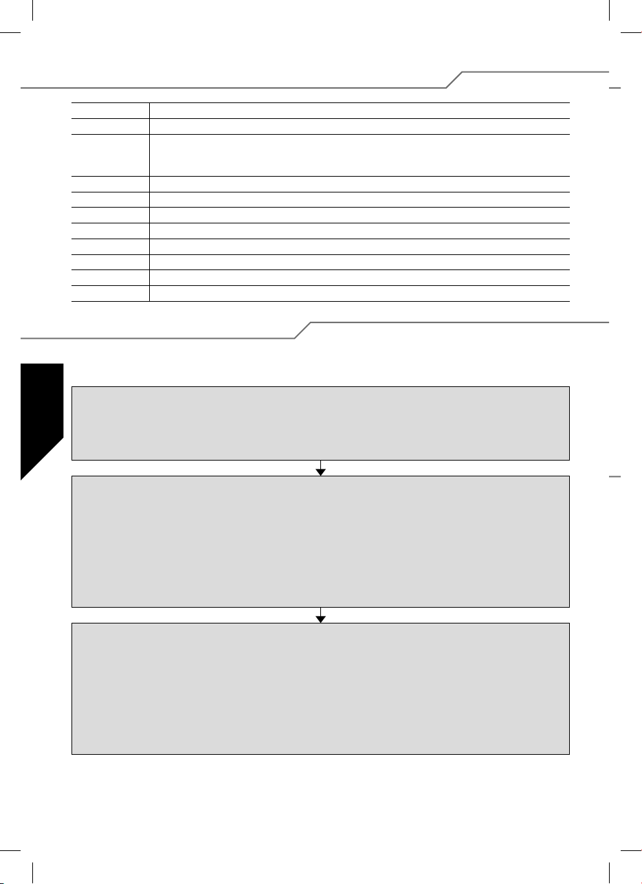
5.1. Caratteristiche del dispositivo e funzioni di protezione
BEC Sistema di alimentazione della ricevente.
POR Protezione in fase di avviamento: impedisce un avviamento indesiderato del motore.
PCO
Spegnimento per sottotensione. Il dispositivo spegne prontamente il motore qualora rileva una batteria quasi
scarica, al ne di sfruttare l’energia rimasta per il comando direzionale del modello e per evitare scariche
eccessive della batteria stessa (sia per batterie NC/NiMH oppure LiPo).
hec Alta frequenza di impulsi per un comando più sensibile, utile per preservare i magneti del motore.
SPS Super Programming System
Cool Power FET Nuova generazione di transistors
WP Protezione contro schizzi d‘acqua (Water Protect)
Opto Separazione di tipo galvanico tra ricevente e disturbi derivanti dal motore.
Filtro RX Spegnimento del regolatore in caso di disturbo o mancanza del segnale trasmittente.
TOP Duplice protezione contro sovraccarichi termici (Thermal Overload Protection).
TP Protezione termica (Thermal Protection)
5.2. Esempio di programmazione
L’esempio seguente illustra l’adattamento del regolatore alla posizione dello stick di comando ed inoltre la programmazione del tipo di modello: AIR con freno attivo.
Programmazione della posizione dello stick di comando
1. Accendere la trasmittente e portare lo stick di comando del gas nella posizione desiderata in avanti.
2. Collegare la batteria di alimentazione con il regolatore (viene emesso un breve segnale acustico).
3. Trascorsi 10 secondi ca. viene emesso un segnale acustico doppio quale conferma dell’avvenuta programmazione della posizione avanti.
4. Portare lo stick di comando in posizione stop; una breve sequenza acustica conferma l’avvenuta programmazione della posizione stop.
5. Scollegare il regolatore dalla batteria di alimentazione.
Programmazione dei parametri del regolatore
1. Accendere la trasmittente e portare lo stick di comando del gas nella posizione in avanti.
2. Collegare la batteria di alimentazione con il regolatore (viene emesso un breve segnale acustico).
3. Trascorsi 10 secondi ca. viene emesso un segnale acustico doppio, dopo ulteriori 3 secondi una sequenza sonora triplice.
4. Il regolatore si trova in modalità di programmazione per il parametro 1 (segnale acustico continuo e lampeggio del LED).
5. Per accedere alla programmazione del parametro 4 (quattro segnali acustici continui e lampeggio del LED per quattro volte), spostare per
quattro volte lo stick da posizione avanti a posizione stop a nuovamente posizione avanti.
6. Portare lo stick di comando da posizione avanti a posizione stop per modi care il parametro.
Lo stick deve poi rimanere in posizione stop per almeno 3 secondi.
7. Selezionare la modalità AIR (il LED si illumina, viene emesso un “Beep” ogni 2 secondi).
8. Portare in ne lo stick di comando da posizione stop a posizione avanti per memorizzare la modi ca effettuata.
Attivazione Air Brake
1. Terminata la memorizzazione del punto precedente, si ritorna nel menu per la programmazione del parametro 4.
2. Per accedere alla programmazione del parametro 3 (triplice segnale acustico continuo e lampeggio del LED per tre volte),
spostare per tre volte lo stick da posizione avanti a posizione stop a nuovamente posizione avanti.
3. Portare lo stick di comando da posizione avanti a posizione stop per modi care il parametro.
Lo stick deve poi rimanere in posizione stop per almeno 3 secondi.
4. Viene segnalato all’utente il tipo di funzione del freno impostato: AIR BRAKE ATTIVO (lampeggio del LED, “Beep” ogni 0,5 s.) oppure AIR
BRAKE DISATTIVATO (LED illuminato, “Beep” ogni 2 s.). Per modi care l’impostazione, spostare velocemente lo stick da posizione stop a
posizione avanti a nuovamente posizione stop.
5. Portare in ne lo stick di comando da posizione stop a posizione avanti per memorizzare la modi ca effettuata.
6. Scollegare il regolatore dalla batteria di alimentazione.
30
Page 31
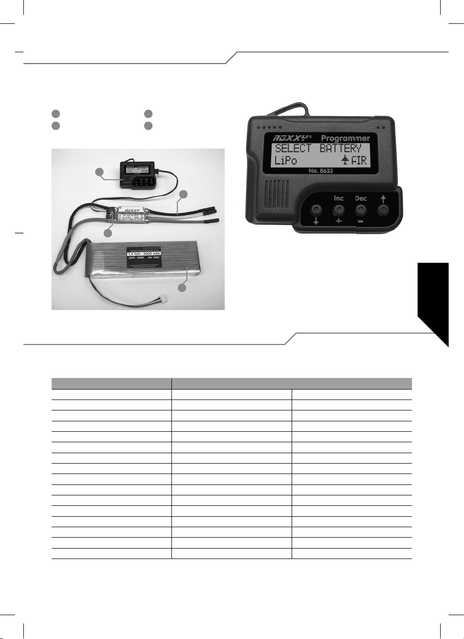
6. Impostazioni con programmatore
Per programmare il regolatore in maniera semplice e speci ca per ciascun modello, è utile impiegare l’apposito programmatore
esterno Art. No. 31 8633. Questo pratico dispositivo consente di programmare in modo facile e veloce tutti i parametri del
regolatore attraverso il suo display LC.
1
Programmatore
2
Cavi di collegamento
3
Regolatore di velocità
4
Batteria di alimentazione
con il motore
1
2
3
Utilizzo del programmatore
L’utilizzo del dispositivo è particolarmente facile: i tasti freccia
consentono la navigazione all’interno del software per accedere
alla modalità di programmazione. Permettono inoltre di cam-
4
biare il tipo di modello impostato qualora vengono mantenuti
premuti contemporaneamente. I due tasti centrali DEC (–) e
INC (+) servono per selezionare o modi care una regolazione.
6.1. Panoramica delle programmazioni disponibili
Salvo alcune poche differenze, tutti i punti di programma sono essenzialmente formati uguali. Per una migliore comprensione, tutti
i valori sono elencati nella tabella sottoindicata.
Heli Boot/Car (Nave-Auto) Air (Aereo)
Tipo batteria Tipo batteria Tipo batteria
Spegnimento sottottensione Spegnimento sottottensione Spegnimento sottottensione
Tipo spegn. motore Tipo spegn. motore Tipo spegn. motore
Verso rotaz. motore Verso rotaz. motore Verso rotaz. motore
Timing motore Timing motore Timing motore
Accelerazione Accelerazione Accelerazione
Start Power Start Power Start Power
Regolatore giri On/Off Reverse Function Tipo freno motore
Caratteristica del regolatore Nr. poli motore Freno motore On/Off
Nr. poli motore Rapporto trasmissione Numero poli motore
Rapporto trasmissione Nr. di giri massimo Rapporto trasmissione
Nr. di giri massimo Nr. di giri medio Nr. di giri massimo
Nr. di giri medio Scrittura dati Nr. di giri medio
Scrittura dati Lettura dati programmazione Scrittura dati
Lettura dati programmazione Copia di sicurezza Lettura dati programmazione
Copia di sicurezza Copia di sicurezza
31
Page 32
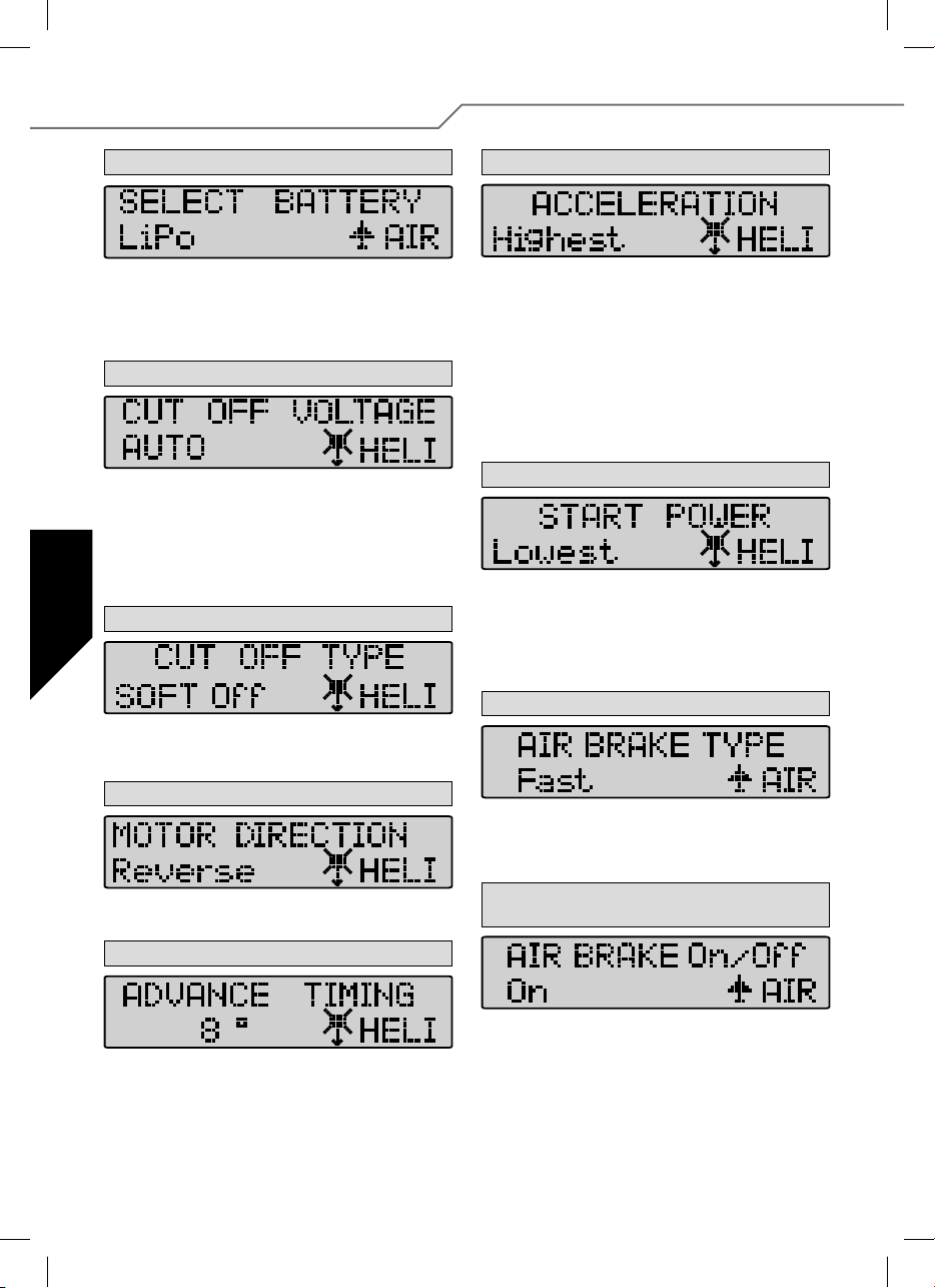
7. Dettagli per la programmazione
1. Battery type (Tipo batteria)
Utilizzare i tasti INC oppure DEC per impostare il tipo di batteria desiderata. Una volta impostato il tipo, è possibile che gli altri parametri
impostati in precedenza risultino fuori dai limiti ammessi per le voci
“CUT OFF VOLTAGE” e “CUT OFF TYPE”. Mediante i tasti DEC e INC si
possono re-impostare tali parametri.
2. Cut Off Voltage (Spegnimento per sottotensione)
Il valore di voltaggio Cut Off (spegnimento per sottotensione) dipende
dal tipo di batteria precedentemente impostato; per una batteria LiPo,
in modalità Auto, il regolatore spegne il motore al raggiungimento di 3 V
per cella. Per una batteria NiCd, lo spegnimento avviene già a 5,5 V
(regolabile). Risulta comunque possibile impostare personalmente il
valore desiderato mediante i tasti INC e DEC, all’interno di un intervallo
compreso tra 4,5 V – 33,0 V.
3. Cut off type (Tipo di spegnimento motore)
Questa modalità permette di impostare il tipo di spegnimento motore
in caso di sottotensione della batteria, scegliendo tra “Soft Off” oppure
“Hard Off” mediante i tasti DEC e INC .
4. Motor Direction (Verso di rotazione motore)
Risulta possibile selezionare il verso di rotazione del motore, tra rotazione
normale o al contrario.
6. Acceleration (Accelerazione)
La modalità Acceleration (accelerazione) consente di impostare l’accelerazione da imporre al regolatore,necessaria per raggiungere il valore
massimo. Tale opzione risulta fondamentale qualora la funzione del
gas venga comandata con un interruttore; permette infatti di regolare l’intervallo di tempo entro cui viene raggiunto il comando “gas al
massimo”.
Esempio: Lowest/accelerazione minima oppure Highest/accelerazione
massima.
Parametri regolabili:
Lowest / Low / Normal / High / Highest (molto basso / basso / normale /
elevato / molto elevato), con selezione attraverso i tasti DEC ed INC.
7. Start Power
All’interno del menu Start Power è possibile regolare la potenza (coppia)
da conferire al motore in fase di avviamento (da fermo). Potenze limitate risultano particolarmente importanti per preservare gli organi di
trasmissione di elicotteri,per esempio. Il menu mette a disposizione i
valori: Lowest / Low / Normal / High / Highest (molto basso / basso /
normale / elevato / molto elevato).
8. Air Brake Type (Tipo di freno motore) – solo per aerei
All’interno del menu Air Mode (Aeromodello), è possibile regolare l’intensità del freno motore, stabilendo la modalità di arresto del motore
(dolce o brusca). Il dispositivo mette a disposizione le voci slow / normal /
fast (lento / normale / veloce), selezionabili attraverso i tasti INC o DEC.
9.
Air Brake On/Off (Freno motore attivato / disattivato)
– solo per aerei
5. Advance Timing (Timing Motore)
Per “advance timing” si intende la funzione di comando “timing motore”
(tempo motore). L’impostazione consente di regolare l’anticipo del campo
di rotazione del motore, analogamente ad una “preaccensione”. Di norma
sono adatti 8° per la maggior parte di motori. Per ottenere l’impostazione
speci ca per il vostro motore, consigliamo i seguenti valori: 0 – 10° motori
brushless normali, 15 – 25° motori brushless cassa rotante.
32
La funzione consente di attivare o disattivare il freno motore.
Page 33
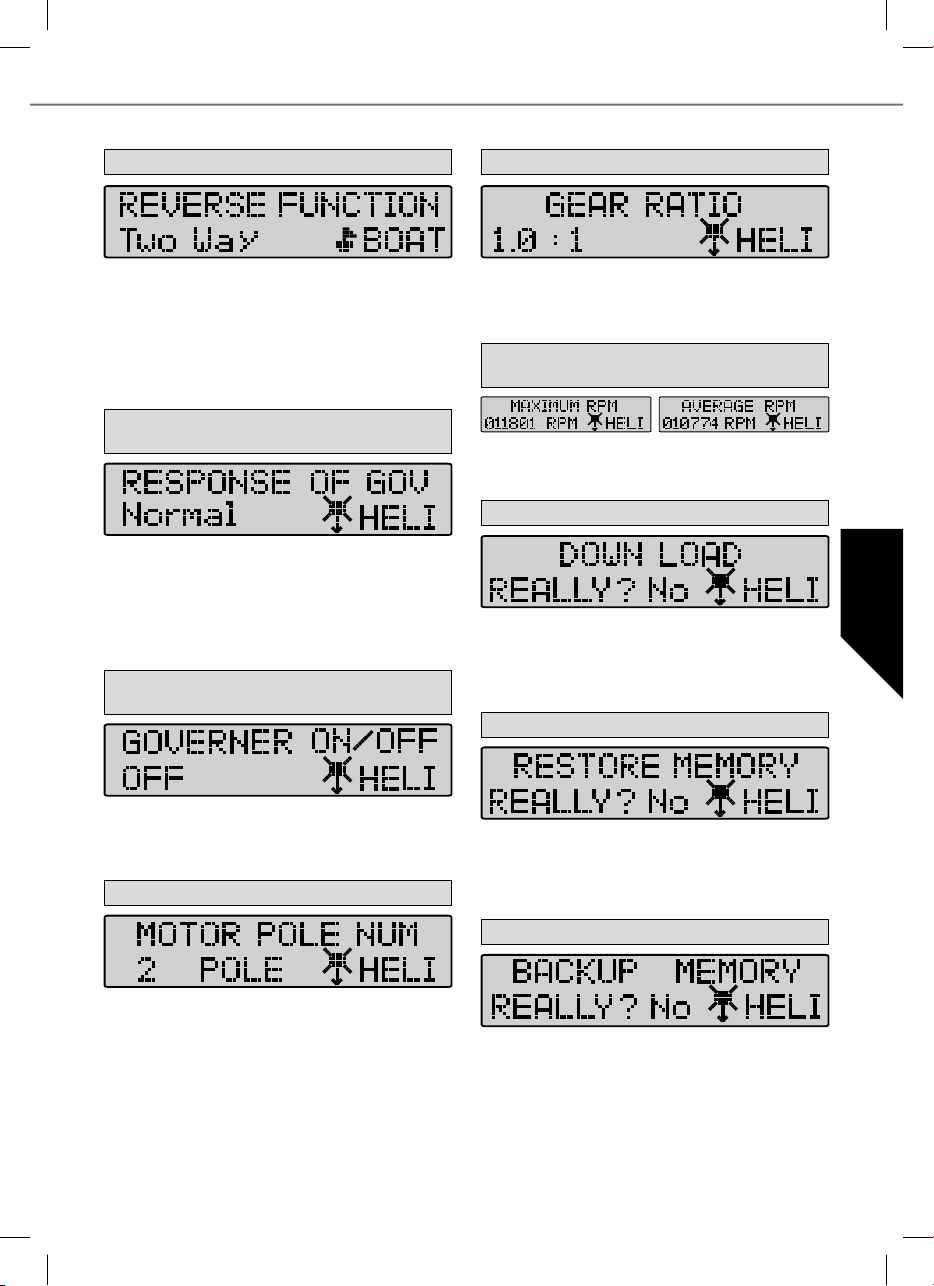
10. Reverse Function (Solo per scafi o auto)
14. Gear ratio (Rapporto di trasmissione)
La funzione Reverse permette di selezionare – per modelli di navi o
auto – se fare funzionare il motore solo in avanti oppure in avanti/
indietro. La voce “One Way” (una direzione) permette di stabilire un solo
verso di funzionamento del motore – selezionabile tra “avanti” oppure
“indietro”. La voce “Two Way Modus” rende il regolatore funzionante in
modalità avanti ed indietro.
Attenzione: le impostazioni possono annullare il verso di funzionamento del motore selezionato in precedenza (punto 4).
11. Response of governor (caratteristica del regolatore) –
solo per elicotteri
Questa voce consente di impostare il campo di funzionamento del regolatore di giri. Risultano selezionabili le voci: Molto basso / basso /
Normale / Alto / Molto alto.
Attenzione: più alto risulta il campo selezionato, maggiore risulterà il
consumo di corrente. Si suggerisce pertanto di selezionare un campo
basso al ne di prolungare l’autonomia della batteria e prolungare quindi la durata del volo.
12. Governor on/off (attivazione/disattivazione del
regolatore di giri) – solo elicotteri
Questo menu consente l’attivazione o la disattivazione del regolatore di
giri. Quest’ultimo stabilizza il numero di giri pre-impostato e lo mantiene
praticamente costante. Selezionare On (attivo) per attivare la stabilizzazione, Off per disattivarla.
13. Motor Pole Number (Numero di poli motore)
L’utente può impostare il rapporto di trasmissione utilizzato sul proprio
modello. Il dispositivo calcolerà quindi, in base a tale valore ed al numero di poli, i valori per la visualizzazione del numero di giri. Risultano
selezionabili rapporti compresi tra 1,0 : 1 no a 25,0 : 1.
15.
Max. RPM & Average RPM
(Visualizzazione numero di giri)
La modalità mostra all’utente il numero di giri massimo e medio del
motore durante l’ultimo volo, sulla base di quanto precedentemente
impostato ai punti 14 e 15.
16. Down Load (scrittura dati)
La funzione “down load” consente di salvare sul regolatore tutti i valori
precedentemente impostati. Premere il tasto INC per avviare l’applicazione; il programmatore emetterà un segnale acustico ogni secondo
no al termine. Qualora si desidera interrompere l’applicazione è suf ciente premere il tasto DEC.
17. Restore memory (lettura dati programmatore)
Questa funzione permette all’utente di aprire e visualizzare tutti i dati
salvati sulla memoria interna del programmatore. Per avviare l’applicazione premere il tasto INC; il programmatore emetterà un segnale
acustico ogni secondo no al termine. Qualora si desidera interrompere
l’applicazione è suf ciente premere il tasto DEC.
18. Backup memory (copia di sicurezza)
Questa funzione consente di impostare il numero di poli del proprio
motore all’interno di un intervallo compreso tra 2 e 36 poli. Il parametro
risulta necessario per poter poi visualizzare il corretto numero di giri.
L’applicazione permette di memorizzare sulla memoria interna del programmatore i valori impostati. Per avviare l’applicazione premere il tasto
INC; il programmatore emetterà un segnale acustico ogni secondo no
al termine. I valori impostati sul regolatore non saranno danneggiati.
Qualora si desidera interrompere l’applicazione è suf ciente premere
il tasto DEC.
33
Page 34

El contenido
1. Introducción ........................................................... 34
1.1. Indicaciones de seguridad ....................................... 34
1.2. Garantía/Exclusión de responsabilidad ..................... 34
1.3. Declaración de conformidad ................................... 34
1.4. Eliminación ............................................................ 35
2. Conexión y características especiales ...................... 35
3. Características técnicas .......................................... 35
4. Programación de las posiciones del stick ................. 36
5. Programación de los parámetros del variador sin
programador .......................................................... 37
5.1. Características y funciones de seguridad ................. 38
5.2. Ejemplo de programación ....................................... 38
6. Ajuste con programador .......................................... 39
6.1. Resumen de las posibilidades de programación ....... 39
7. Detalles para la programación ................................. 40
1. Introducción
Pequeña y ligera serie de variadores para motores con la nueva tecnología Cool Power FET con un rendimiento especial y con
una amplia aplicación para aeromodelos, barcos, coches y helicópteros eléctricos. Estos variadores son especialmente adecuados
para la serie de motores BL ROXXY, pero también para otros motores BL. Antes de conectar y poner en marcha el variador,
leer atentamente estas instrucciones.
1.1. Indicaciones de seguridad
- Tener en cuenta lasa características técnicas del variador.
-
Tener en cuenta la polaridad de todos los cables de conexión.
- Evitar cualquier corto circuito.
- Instalar el variador y cubrir el variador de forma que no
pueda entrar en contacto con grasa, aceite o agua.
- Proveer suficiente circulación de aire.
- Durante la puesta en funcionamiento, no tocar piezas que
giran – puede sufrir heridas.
- Fijar los motores de forma segura.
No nos responsabilizamos de modificaciones técnicas.
1.2. Garantía/Exclusión de responsabilidad
La empresa MULTIPLEX Modellsport GmbH & Co.KG no asume
ningún tipo de responsabilidad por posibles daños, pérdidas o
costes derivados directa o indirectamente del mal uso o uso
indebido del aparato. En la medida permitida por la ley, la
obligación de indemnización de la empresa MULTIPLEX Modellsport GmbH & Co.KG se limita, independientemente del motivo
jurídico que la genere, al valor en factura de la mercancía de
MULTIPLEX Modellsport GmbH & Co.KG directamente implicada
en el hecho causante del daño. La anterior disposición no es
aplicable en el caso de que las disposiciones legales de
obligado cumplimiento establezcan una responsabilidad
ilimitada de MULTIPLEX Modellsport GmbH & Co.KG por dolo
o negligencia grave.
Todos nuestros productos tienen una garantía acorde con las
disposiciones legales aplicables en cada momento En caso de
garantía, póngase en contacto con el establecimiento en el que
adquirió el producto. La garantía no cubre fallos provocados por:
· Uso indebido.
· Falta de mantenimiento, mantenimiento incorrecto,
incumplimiento de intervalos de mantenimiento o
mantenimiento efectuado por un servicio no autorizado.
· Conexionado incorrecto.
· Empleo de recambios no originales MULTIPLEX.
·
Modi caciones o reparaciones no efectuadas por MULTIPLEX
o un servicio técnico autorizado MULTIPLEX.
· Daños accidentales o intencionados.
· El desgaste normal.
· Funcionamiento no conforme con las especi caciones
técnicas o empleo de componentes de otros fabricantes.
MULTIPLEX Modellsport GmbH & Co.KG
Westliche Gewerbestrasse 1 · D-75015 Bretten-Gölshausen
Multiplex/HiTEC Service: +49 (0) 7252 - 5 80 93 33
1.3. Declaración de conformidad
Multiplex Modellsport GmbH & Co. KG declara por la presente, que este producto cumple con los requisitos básicos y demás
preceptos relevantes de las directivas CE correspondientes. La declaración de conformidad original gura en las descripciones
respectivas de los aparatos dentro de la página de Internet www.multiplex-rc.de.
34
Page 35
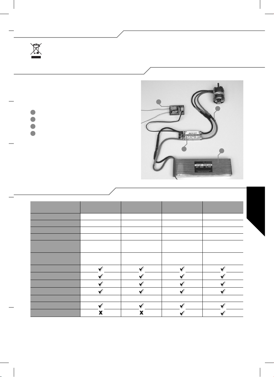
1.4. Eliminación
Este símbolo signi ca, que es necesario, desechar los aparatos eléctricos y electrónicos al nal de su uso, separadamente de la basura doméstica. Lleve a un centro de recogida comunal o a un centro de reciclaje. Esto vale para todos
los países de la C.C.E.E. así como para otros países europeos con sistemas de recogida separados.
2. Conexión y características especiales
Preparar el cable rojo (positivo) y el cable negro (negativo),
utilizando un sistema de enchufe adecuado para la conexión
en la batería de propulsión. Aislar todas las soldaduras con
tubo retráctil.
1
Receptor
2
Conexión motor
3
Variador
4
Batería de propulsión
1
2
3
4
3. Características técnicas
BL 908
N° 31 8627
Consumo 8 A 18 A 30 A 30 A
Tiempo breve 12 A 22 A 35 A 35 A
Dimensiones (mm) 35 x 22 x 7 38 x 22 x 7 49 x 25 x 10 49 x 25 x 10
Peso grs. 15 g 25 g 29 g 29 g
Cantidad de elementos 6...12 NC/NiMh
2...4 LiPo
BEC 5,5 voltios max. 2 A 5,5 voltios max. 2 A 5,5 voltios max. 2 A 5,5 voltios max. 2 A
aps
Filtro RX
PCO
POR
hec 32 kHz 32 kHz 32 kHz 32 kHz
TP
Cool Power FET
BL 918
N° 31 8628
6...12 NC/NiMh
2...4 LiPo
BL 930
N° 31 8629
6...12 NC/NiMh
2...4 LiPo
BL 930-6
N° 31 8630
6...18 NC/NiMh
2...6 LiPo
35
Page 36
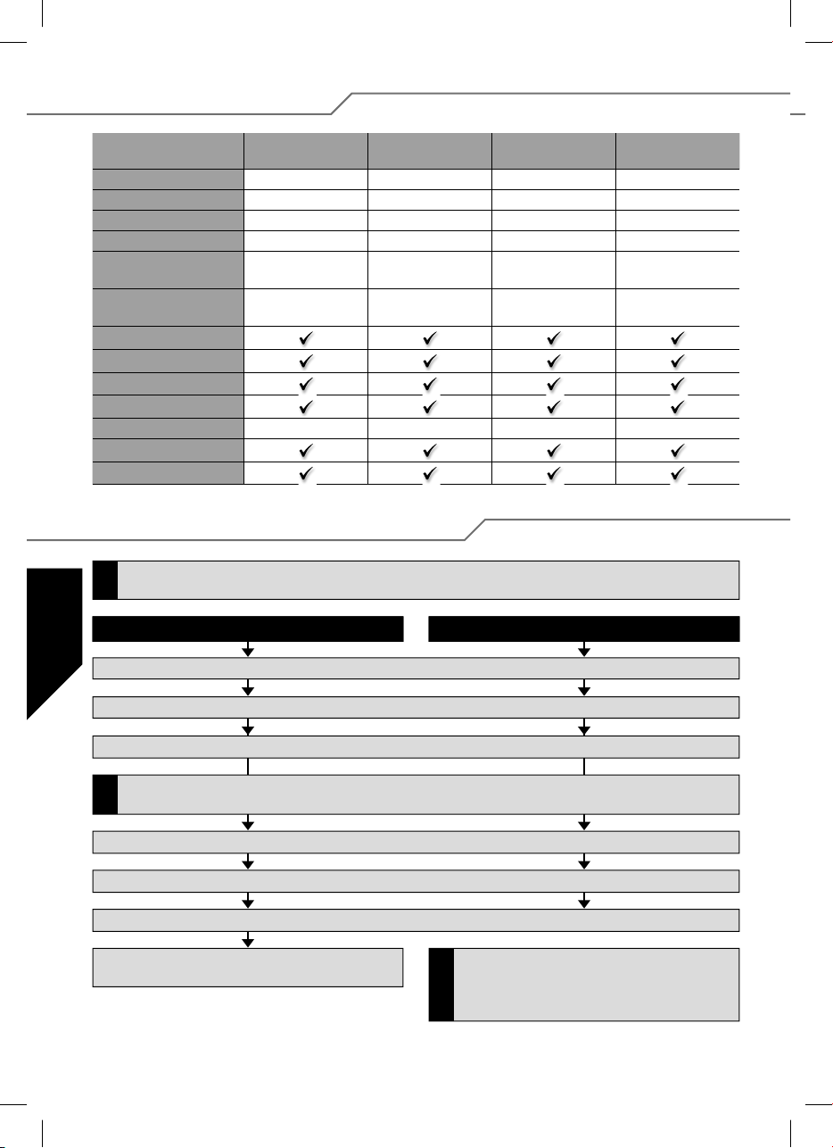
3. Características técnicas
BL 940-6
N° 31 8631
Consumo 40 A 50 A 60 A 100 A
Tiempo breve 50 A 60 A 70 A 110 A
Dimensiones (mm) 66 x 25 x 10 66 x 25 x 10 66 x 25 x 10 76 x 26 x 13
Peso grs. 47 g 49 g 49 g 67 g
Cantidad de elementos 6...18 NC/NiMh
2...6 LiPo
BEC 5,5 voltios
max. 3 A/kurz. 5 A
aps
Filtro RX
PCO
POR
hec 32 kHz 32 kHz 32 kHz 32 kHz
TP
Cool Power FET
BL 950-6
N° 31 8632
6...18 NC/NiMh
2...6 LiPo
5,5 voltios
max. 3 A/kurz 5 A
BL 960-6
N° 31 8634
6...18 NC/NiMh
2...6 LiPo
5,5 voltios
max. 3 A/kurz. 5 A
4. Programación de las posiciones del stick
Si se quiere modi car el tipo del modelo (parámetro 4 o parámetro 5), hay que ajustar este parámetro antes de modi car
otros parámetros.
!
Adelante, tstop, atrás Adelante y stop (Tipo de modelo Avion/Helicoptero)
BL 9100-6
N° 31 8635
6...18 NC/NiMh
2...6 LiPo
5,5 voltios
max. 3 A/kurz. 5 A
1. Conectar el variador según el dibujo de conexión (excepto la alimentación de tensión).
2. Conectar la emisora y poner el stick de gas en posición adelante.
3. Conectar la alimentación de la tensión en el variador.
Si se ilumina el LED después de punto 2, accionar el servo reverse en la emisora, interrumpir la alimentación con el variador
y volver a empezar con punto 1. La posición adelante del stick debe estar cerca del tope mecánico.
!
4. El variador lo con rma con una secuencia breve de tonos.
5. Al cabo de 10 segundos suena una secuencia de tonos dobles como con rmación a la programación de la posición adelante.
6. Poner el stick del gas en la posición stop, una secuencia corta de tonos con rma la programación de la posición stop.
7. Poner el stick de gas en posición atrás, una secuencia de
tonos triples con rma la programación de la posición atrás.
La programación de las posiciones del stick adelante y
atrás de variadores que tienen solamente adelante, es
análoga hasta (punto 6), lo cual se con rma con una
!
secuencia de tonos triples.
36
Page 37
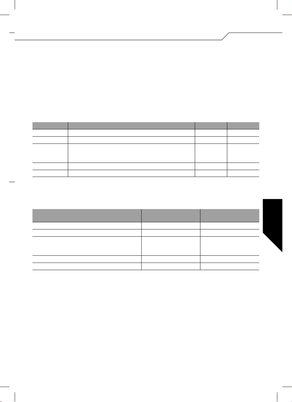
5. Programación de los parámetros del variador sin programador
Se pueden programar cinco parámetros.
Se entra en el modo de programación de la siguiente manera:
1. Conectar el variador según el dibujo de conexión (excepto
de la alimentación).
2. Conectar la emisora y poner el stick de gas en posición
adelante.
3. Conectar la alimentación de la tensión en el variador.
4. El variador lo con rma con una secuencia de tonos cortos.
5. Al cabo de aprox. 10 segundos suena una secuencia de
dos tonos, después de otros 3 segundos aprox. una
secuencia de tres tonos.
Tipo de Parámetro Beep LED
Parámetro 1 Tipo de batería
Parámetro 2 Sentido de giro
Parámetro 3 - Freno marcha/paro (avión)
- Governor marcha/paro (helicóptero)
- Atrás marcha/paro (coche,barco)
Parámetro 4 Tipo de modelo avión/helicóptero
Parámetro 5 Tipo de modelo barco/coche
Para modi car el parámetro, es necesario cambiar el stick
del gasdesde la posición adelante a la posición stop. El stick
de gas debe permanecer como mínimo 3 segundos en la posición stop.
Tipo de Parámetro LED ILUMINADO
Tipo de batería LiPo NiCD/NiMH
Sentido de giro Normal Reverse
Freno (avión)
Governor (helicóptero)
Atrás (coche,barco)
Tipo de modelo (AVION/HELICOPTERO) AVION HELICOPTERO
Tipo de modelo (BARCO/COCHE) BARCO COCHE
Ahora el variador indica mediante un beep único continuado y
un parpadeo del LED, la selección de parámetro 1.
Se seleccionan los parámetros a programar a través de la
siguiente secuencia del stick del gas: Cambio corto del stick
de gas desde la posición adelante a la posición de stop y de
nuevo a la posición adelante. Ahora el variador indica con un
doble beep continuado y parpadeo del LED la selección del
parámetro 2. Para seleccionar los parámetros 3, 4 y 5, volver
a repetir la secuen- secuencia del stick de gas descrito anteriormente.
1 x 1 x
2 x 2 x
3 x 3 x
4 x 4 x
5 x 5 x
El cambio real del parámetro mismo se hace mediante un
cambio rápido del stick de gas desde la posición stop a la
posición adelante y otra vez a la posición de stop.
Beep cada 2 seg.
PARO
PARO
PARO
LED parpadea
Beep cada 0,5 seg.
MARCHA
MARCHA
MARCHA
Para memorizar una modi cación, cambiar rápidamente el
stick del gas desde la posición stop a la posición adelante.
La nalización y el traspaso de los ajustes de la programación
se memorizan al interrumpir la alimentación de la tensión. El
variador está programado y preparado para el uso.
37
Page 38
5.1. Características y funciones de seguridad
BEC Alimentación del receptor
POR Protección al arranque, evita arrancar el motor sin querer.
PCO Desconexión por baja tensión, el motor se desconecta a tiempo cuando la batería está descargada, para
reservar su ciente capacidad para el mando para evitar una descarga total de l batería (a elección para
baterías NiCad/NiMH o para baterías Lipoly).
hec Alta frecuencia de tacto para un mando del motor sensible y respetuoso con el magneto.
SPS Super Programming System
Cool Power FET Nueva generación de transistores
WP Protegido a las salpicaduras del agua (Water Protect)
Opto Separación galvánica entre interferencias del motor y del receptor.
Filtro RX Desconecta el variador cuando falta la señal de la emisora o cuando no es válida.
TOP Doble protección a la sobrecarga (Termal Overload Protection)
TP Seguro térmico (Termal Protection)
5.2. Ejemplo de programación
Con este ejemplo se explica la adaptación del variador a la posición individual del stick y a continuación la programación del tipo de modelo: AIR y freno ON:
Programación de las posiciones del stick
1. Conectar la emisora y poner el stick de gas en la posición adelante deseada.
2. Conectar la alimentación al variador (suena una secuencia corta de tonos).
3. Al cabo de aprox. 10 segundos suena una secuencia de dos tonos como con rmación de la programación de la posición adelante.
4. Poner el stick de gas en la posición stop, una secuencia corta de tonos con rma la programación de la posición stop.
5. Alimentación, interrupción.
Programación de los parámetros del variador
1. Conectar la emisora y poner el stick de gas en posición adelante.
2. Conectar la alimentación al variador (suena un beep corto).
3. Al cabo de 10 segundos aprox. suena una secuencia de dos tonos, después de aprox. 3 segundos más sigue una secuencia de tres tonos.
4. Ahora el variador se encuentra en el modo de programación parámetro 1 (beep único continuado y el LED parpadea).
5. Al cambiar cuatro veces el stick del gas de la posición delante a la posición stop y otra vez a la posición delante, se llega a parámetro 4
(beep continuado 4 veces y el LED parpadea cuatro veces).
6. Para cambiar el parámetro, es necesario cambiar primero el stick de gas desde la posición adelante a la posición stop.
El stick del gas debe permanecer como mínimo durante 3 segundos en la posición stop.
7. Seleccionar el modo AIR (LED iluminado/beep cada 2 seg.).
8. Se memoriza cambiando el stick del gas desde la posición stop a la posición adelante.
Ajustar Air Brake On
1. Después de la memorización arriba indicada, el variador se vuelve a encontrar en la selección de parámetros, parámetro 4.
2. Cambiando cuatro veces el stick de gas desde la posición adelante a la posición stop y otra vez a la posición delante, se llega al parámetro
3 (beep continuado 3 veces y el LED parpadea tres veces).
3. Para cambiar el parámetro, es necesario cambiar primero el stick del gas de la posición adelante a la posición stop.
El stick de gas debe permanecer como mínimo 3 segundos en la posición stop.
4. Ahora se indica la función ajustada actual del freno. Air Brake ON (LED parpadea/beep cada 0,5 seg.) o Air Brake OFF (LED iluminado/beep
cada 2 seg.). Si es necesario, modi car el parámetro, cambiando rápidamente el stick del gas de la posición stop a la posición delante y
otra vez a la posición stop.
5. Se memoriza la modi cación al cambiar el stick del gas de la posición stop a la posición delante.
6. Alimentación, interrupción.
38
Page 39
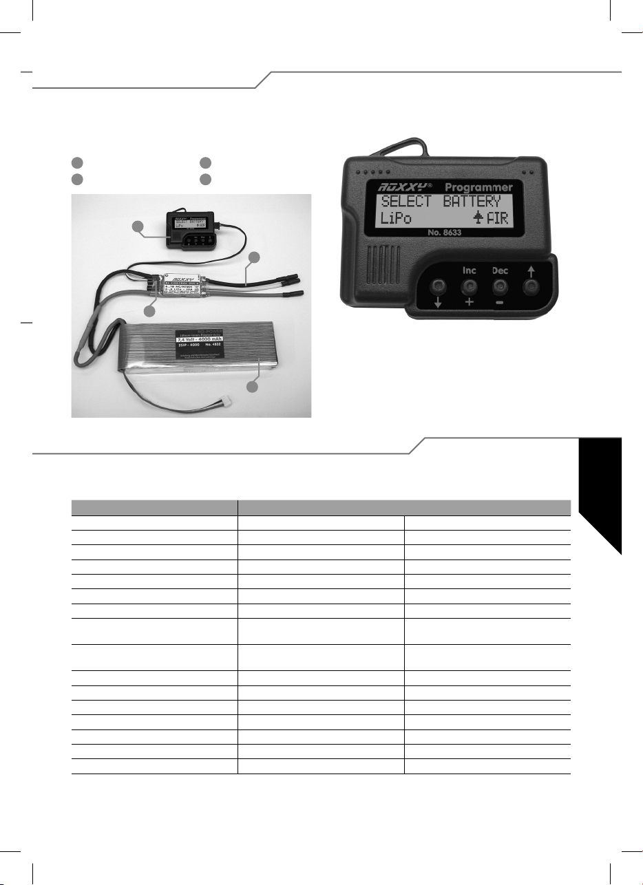
6. Ajuste con programador
Para programar el variador de forma más simple y más especí co respecto al modelo, utilizar el programador de nº 31 8633.
Esta unidad de mando clara, hace posible programar los parámetros a ajustar de forma segura y rápida a través de un display de LC.
1
Programador
2
Conexión motor
1
3
3
Variador
4
Batería de propulsión
2
Navegación con programador
Usar el programador es muy fácil. Con la echa exterior, mover
las teclas o hacía arriba o hacía abajo para llegar al modo de
programación de su elección. Además se cambia el tipo del
4
modelo, pulsando las dos teclas con echa. Las dos teclas
del centro DEC (–) y INC (+) sirven para seleccionar o para
modi car un ajuste.
6.1. Resumen de las posibilidades de programación
Salvo unas pequeñas diferencias, todos los puntos de programación están concebidos de la misma manera. Para dejarlo más
claro, hemos alistado todos los valores en la tabla a continuación.
Helicóptero Barco/Coche Air (Vuelo)
Select Battery (Tipo de batería) Select Battery (Tipo de batería) Select Battery (Tipo de batería)
Cut Off Voltage (Tensión de desconexión) Cut Off Voltage (Tensión de desconexión) Cut Off Voltage (Tensión de desconexión)
Cut Off Type (Tipo paro motor) Cut Off Type (Tipo paro motor) Cut Off Type (Tipo paro motor)
Motor Direction (Sentido de giro del motor) Motor Direction (Sentido de giro del motor) Motor Direction (Sentido de giro del motor)
Advance timing (Timing motor) Advance timing (Timing motor) Advance timing (Timing motor)
Acceleration (Aceleración) Acceleration (Aceleración) Acceleration (Aceleración)
Start Power Start Power Start Power
Response of Governor
(característica de regulación)
Governor On/Off
(Regulador de revol. marcha/paro)
Motor Pole Num (Cantidad de polos motor) Gear Ratio (Desmultiplicación engranaje) Motor Pole Num (Cantidad de polos motor)
Gear Ratio (Desmultiplicación engranaje) Max. RPM (Indicación revoluciones max.) Gear Ratio (Desmultiplicación engranaje)
Max. RPM (Indicación revoluciones max.) Average RPM (Promedio de revoluciones) Max.RPM (Indicación revoluciones max.)
Average RPM (Promedio de revoluciones) Down Load (Descargar datos) Down Load (Promedio de revoluciones)
Down Load (Descargar datos) Restore Mem. (Leer datos programados) Down Load (Descargar datos)
Restore Mem. (Leer datos programados) Backup Mem. (Copia de seguridad) Restore Mem. (Leer datos programados)
Backup Mem. (Copia de seguridad) Backup Memo. (Copia de seguridad)
Reverse Function (Función reverse) Air Brake Type (tipo freno motor)
Motor Pole Num (Cantidad de polos motor) Airbrake On/Off (Motorbremse Ein/Aus)
39
Page 40

7. Detalles para la programación
1. Battery Type (tipo de batería)
Para ajustar el “tipo de batería deseado”, utilizar la tecla DEC o INC.
Después de haber seleccionado un nuevo tipo de batería, puede ser
que se haya modi cado el parámetro preajustado en el área “CUT OFF
VOLTAGE” y “CUT OFF TYPE”. Se seleccionan siempre los modos con
las teclas DEC e INC.
2. Cut Off Voltaje (tensión de desconexión)
La tensión de desconexión se orienta según el tipo de batería seleccionado. Si se trata de una batería Lipo en el modo de coches, el variador desconecta con 3 V por elemento, pero si se trata de una batería
NiCad, entonces desconecta ya con 5,5 V (tipo de desconexión seleccionable). No obstante, puede seleccionar el valor Vd. mismo por medio
de las teclas DEC e INC. La escala llega de 4,5V – 33,0 V.
3. Cut Off Type (tipo desconexión motor)
En el modo “tipo de desconexión del motor” puede ajustar el tipo de
desconexión en el caso de una eventual tensión baja. Se puede usar
“Soft Off” o “Hard Off”. Volver a seleccionar los modos mediante las
teclas DEC e INC.
4. Motor Direction (sentido de giro del motor)
En el modo “sentido de giro del motor”, puede elegir entre el sentido de
giro normal e inverso de su motor.
5. Advance Timing (timing motor)
6. Acceleration (aceleración)
En el modo de aceleración, se ajusta en que tiempo el variador alcanza
el valor máximo. Esto es importante, cuando se actúa con un conmutador sobre la función del gas, para jar el retardo con que velocidad se
cambia a “gas a fondo”.
Ejemplo: Lowest/aceleración mínima o Highest/aceleración máxima.
Parámetros seleccionables: Lowest / Low / Normal / High / Highest
(muy bajo / bajo / normal / alto / muy alto), uso mediante teclas DEC
e INC.
7. Start Power
En el menú Start Power, se ajusta la potencia de arranque (par), con la
cual el motor arranca (desde punto muerto). Cuando se usan helicópteros, conviene seleccionar valores pequeños para cuidar la rueda
dentada. Se puede seleccionar Lowest / Low / Normal / High / Highest
(muy bajo / bajo / normal / alto / muy alto).
8. Air Brake Type (tipo de freno motor – solo para
aeromodelos)
En el modo AIR (aeromodelo) se puede ajustar la e cacia del freno motor, por tanto se puede determinar si el motor se para de forma suave
o de golpe. Mediante las teclas DEC e INC se pueden seleccionar los
modos Slow / Normal / Fast (suave-normal-fuerte).
9.
Air Brake On/Off (freno motor marcha paro, solamente
para aeromodelos)
Hay que entender el Advance Timing como timing del motor. Con esta
selección se puede adelantar el campo de giro, causando un “avance
del encendido”. En general, 8º suele ser adecuado para la mayoría
de motores. Para seleccionar un setup especial para su motor, recomendamos los siguientes valores: 0º – 10º para motores con inducido
interior, 15º – 25º para motores con el inducido exterior.
40
En este punto del menú, se puede poner en marcha o parar el freno
motor a elección.
Page 41
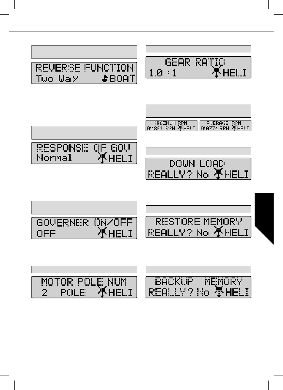
10. Reverse Function (función reverse – solamente en
el modo barco + coche)
Con la función reverse, se puede seleccionar en el modo barcos o coches, si el motor trabaja solamente en una dirección o hacía adelante/
atrás. En el modo “One Way” (dirección única) se determina el sentido
de giro del motor – adelante o atrás. En el modo “Two Way”, el variador
está ajustado para el uso adelante/atrás.
Atención: Al modi car el sentido de giro del motor (motor direction), se
pueden anular los ajustes.
11.
Response of Governor (característica de regulación)
solamente para helicópteros
En este modo se ajustan las características de regulación de un regulador de revoluciones. Se pueden seleccionar los áreas slowest / slow /
normal / fast / fastest (muy lento / lento / normal / rápido / muy rápido).
Atención: Cuando más rápido el valor seleccionado, tanto más corriente requiere la batería. Para cuidar el variador y la batería y para
aumentar la duración de vuelo, conviene escoger un ajuste más bajo.
12. Governor On /Off (regulación de las revoluciones
marcha/paro), solamente para helicópteros
14. Gear Ratio (desmultiplicación engranajes)
En este nivel de ajuste, puede entrar su desmultiplicación individual de
los engranajes. Según la cantidad de polos del motor y la desmultiplicación de los engranajes, se calcula el valor para la indicación de
las revoluciones. Los valores ajustables van de 1,0 : 1 hasta 25,0 : 1.
15.
Max. RPM & Average RPM (Indicación de las
revoluciones)
Este modo indica las revoluciones máximas y promedias del último
vuelo, teniendo en cuenta los valores ajustados de punto 14 y 15.
16. Down Load (descargar datos)
Con el Down Load se descargan los valores ajustados al variador. Con
la tecla INC se inicia la aplicación, el programador hace un tono beep
cada segundo hasta nalizar la aplicación. Si quiere interrumpir el proceso, pulsar DEC.
17. Restore Memory (leer los datos del programador)
En este menú, se conecta o se apaga el regulador de revoluciones. Este
estabiliza las revoluciones preajustadas y las mantiene prácticamente
constante. Modo On (Marcha) para estabilizar o Off (PARO) para no
estabilizar.
13. Motor Pole Number (Cantidad de polos del motor)
En el modo Motor Pole Number, puede seleccionar de cuantos polos
dispone su motor. Este valor es importante para indicar las revoluciones
exactas. El valor seleccionado alcanza de 2 hasta 36 polos.
Con Restore Memory se abren los valores grabados en la memoria del
programador. Se inicia la aplicación con la tecla INC, el programador
hace un tono beep cada segundo hasta nalizar la aplicación. Si quiere
interrumpir el proceso, pulsar DEC.
18. Backup Memory (copia de seguridad)
En el Backup Memory, se graban los valores ajustados en la memoria
del programador. Iniciar la aplicación con la tecla INC, el programador
hace un tono beep cada segundo hasta nalizar la aplicación. No se
perjudican los valores ajustados en el variador. Si quiere interrumpir el
proceso, pulsar DEC.
41
Page 42

Spokojený
1. Všeobecny popis .................................................. 42
1.1. Bezpečnostní pokyny ........................................... 42
1.2. Záruka .................................................................. 42
1.3. Prohlášení o shodě ce ......................................... 42
1.4. Recyklace (EU) .................................................... 43
2. Zapojení a zvláštnosti .......................................... 43
3. Technická data ..................................................... 43
4. Programování pozic kniplů ................................... 44
5. Programování parametrů regulátoru
bez programátoru ................................................. 45
5.1. Vlastnosti a ochranné funkce ............................... 46
5.2. Příklad programování ........................................... 46
6. Nastavování pomocí programátoru ...................... 47
6.1. Přehled možností programování .......................... 47
7. Podrobnosti k programování ................................ 48
1. Všeobecny popis
Malý lehký regulátor nové Cool Power technologie, díky které je regulátor obzvlášt výkonný a lze jej použít v r zných
odv tvích modela iny pro letadla, lod , auta i vrtulníky. Regulátory jsou vhodné zejména pro st ídavé motory Roxxy,
mén je lze použít i pro ostatní st ídavé motory. P ed zapojením a uvedením do provozu si pozorn pro t te tento Návod.
nic-
1.1. Bezpečnostní pokyny
- Dbejte technických dat regulátoru.
- Dbejte na správnou polaritu všech kabelů.
- Zabraňte zkratu.
- Regulátor zabudujte popř. zabalte tak, aby nepřišel
do kontaktu s mastnotou, olejem nebo vodou.
- Zajistěte regulátoru dostatečné chlazení.
- Při uvedení do provozu dávejte pozor, abyste se
nedostali do kontaktu s točící se vrtulí.
Technické změny vyhrazeny.
1.2. Záruka
Zaručujeme, že naše produkty jsou v souladu s aktuálně platnými zákonnými ustanoveními. Na vyrobek se poskytuje
zaruka 24 měsiců od data prodeje. Pokud si přejete uplatnit výrobek reklamovat, požadavek na záruční opravu, prosím,
uplatněte v prodejně, kde jste výrobek zakoupili.
· Nesprávným nebo nevhodným použitím.
CZ
· Opožděnou, nesprávnou nebo vůbec neprovedenou
údržbou, nebo údržbou provedenou neautorizo vaným servisem.
· Nesprávným zapojením.
· Použitím jiného příslušenství než originálních
produktů fi rmy MULTIPLEX.
· Úpravou nebo opravou, která nebyla provedena
fi rmou MULTIPLEX nebo autorizovaným servisním
střediskem MULTIPLEX.
· Náhodným nebo úmyslným poškozením.
· Normálním opotřebením a stárnutím.
· Provozem zařízení mimo provozní limity uvedenými
ve specifi kaci nebo spolu se zařízením vyráběným
jinými výrobci.
MULTIPLEX Modellsport GmbH & Co.KG
Westliche Gewerbestrasse 1 · D-75015 Bretten-Gölshausen
Multiplex/HiTEC Service: +49 (0) 7252 - 5 80 93 33
1.3. Prohlášení o shodě ce
MULTIPLEX Modellsport GmbH & Co. KG tímto prohlašuje, že Roxxy Series Controller je ve shodě se základními
požadavky a dalšími příslušnými ustanoveními harmonizovaných evropských směrnic a norem. To znamená, že jste
se stali vlastníkem výrobku, jehož konstrukce splňuje ochranná kriteria Evropské unie vztahující se k bezpečnému
provozu zařízení. Plný text CE prohlášení o shodě je možno získat na níže uvedené adrese MULTIPLEX Modellsport
GmbH & Co.KG.
42
Page 43
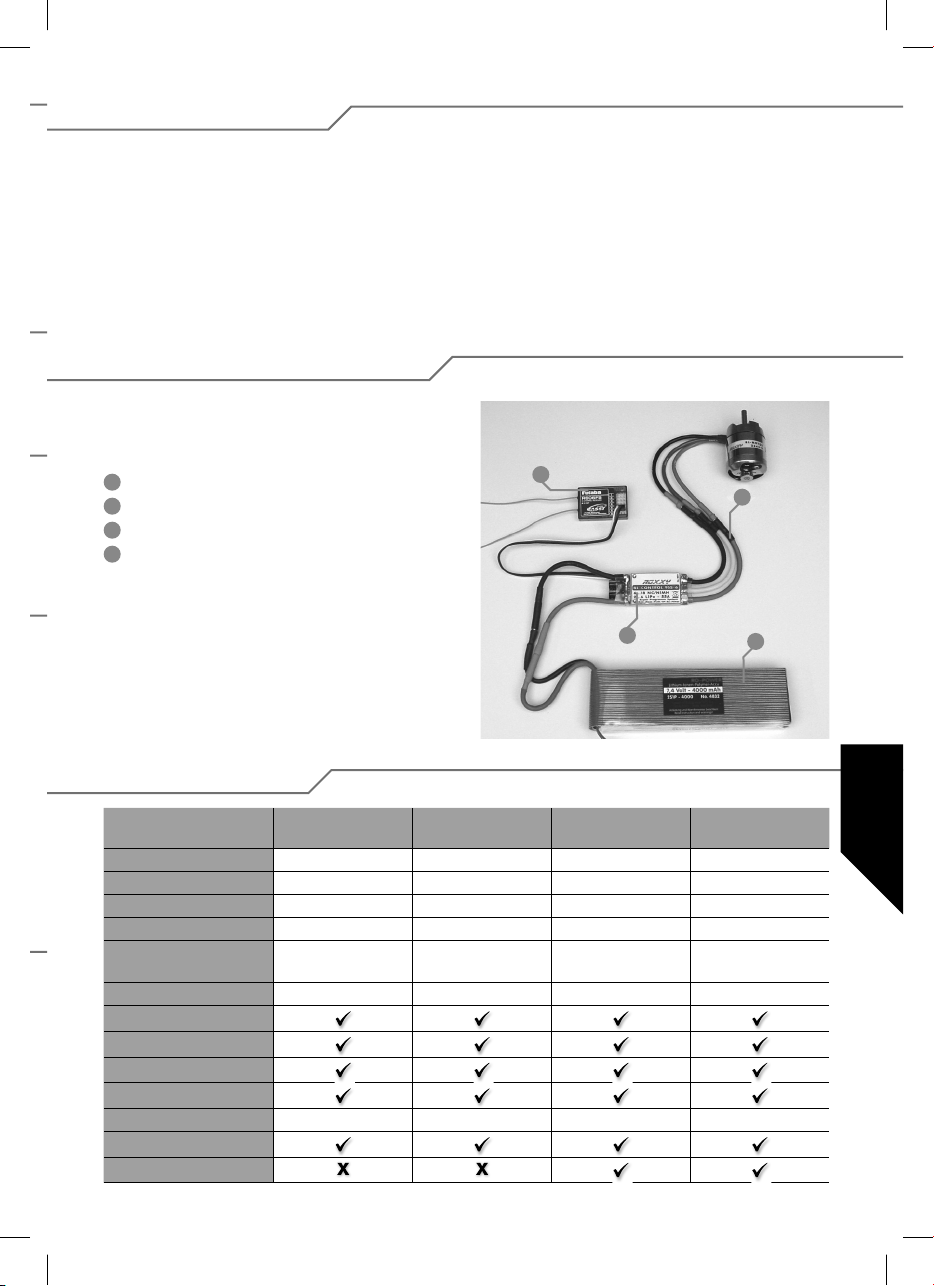
1.4. Recyklace (EU)
Elektrická zařízení opatřená symbolem přeškrtnuté popelnice nesmějí být vyhazována do běžného domácího
odpadu, namísto toho je nutno je odevzdat ve specializovaném zařízení pro sběr a recyklaci.
V zemích EU (Evropské unie)
zení vyhazována do běžného domácího odpadu (WEEE
- Waste of Electrical and Electronic
dace elektrických a elektronických zařízení, směrnice
2002/96/EG).
nesmějí být elektrická zaří-
Equipment - Likvi-
2. Zapojení a zvláštnosti
Připravte červený (plus) a černý (minus) kabel pomocí
vhodných konektorů na propojení s pohonnými články.
Všechna letovaná místa zaizolujte smršťovací bužírkou.
1
Přijímač
2
Zapojení motoru
3
Regulátor
4
Pohonná baterie
Nežádoucí zařízení můžete dopravit do nejbližšího zaří-
zení pro sběr nebo recyklačního střediska. Zařízení poté
budou likvidována nebo recyklována bezpečným způso-
bem zdarma. Odevzdáním nežádoucího zařízení můžete
učinit důležitý příspěvek k ochraně životního prostředí.
1
2
3
4
3. Technická data
BL 908
č. 31 8627
Proud motoru 8 A 18 A 30 A 30 A
Proud motoru max. 12 A 22 A 35 A 35 A
Rozméry (mm) 35 x 22 x 7 38 x 22 x 7 49 x 25 x 10 49 x 25 x 10
Hmotnost (g) 15 g 25 g 29 g 29 g
Typ aku 6...12 NC/NiMh
2...4 LiPo
BEC 5,5 Volt max. 2 A 5,5 Volt max. 2 A 5,5 Volt max. 2 A 5,5 Volt max.2 A
SPS
Filtro RX
PCO
POR
hec 32 kHz 32 kHz 32 kHz 32 kHz
TP
Cool Power FET
BL 918
č. 31 8628
6...12 NC/NiMh
2...4 LiPo
BL 930
č. 31 8629
6...12 NC/NiMh
2...4 LiPo
BL 930-6
č. 31 8630
6...18 NC/NiMh
2...6 LiPo
43
CZ
Page 44
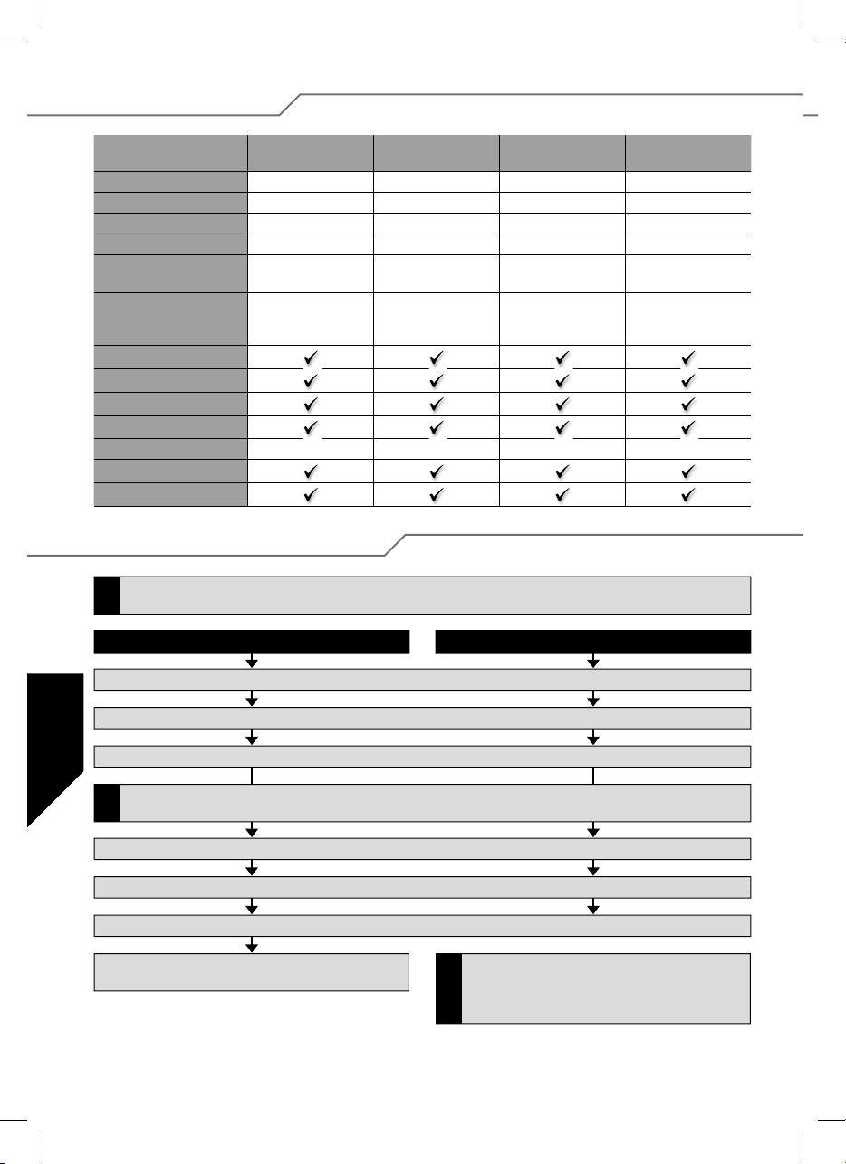
3. Technická data
BL 940-6
č. 31 8631
Proud motoru 40 A 50 A 60 A 100 A
Proud motoru max. 50 A 60 A 70 A 110 A
Rozméry (mm) 66 x 25 x 10 66 x 25 x 10 66 x 25 x 10 76 x 26 x 13
Hmotnost (g) 47 g 49 g 49 g 67 g
Typ aku 6...18 NC/NiMh
2...6 LiPo
BEC 5,5 Volt
max. 3 A/špi kov
5 A
SPS
Filtro RX
PCO
POR
hec 32 kHz 32 kHz 32 kHz 32 kHz
TP
Cool Power FET
BL 950-6
č. 31 8632
6...18 NC/NiMh
2...6 LiPo
5,5 Volt
max. 3 A/špi kov
5 A
BL 960-6
č. 31 8634
6...18 NC/NiMh
2...6 LiPo
5,5 Volt
max. 3 A/špi kov
5 A
BL 9100-6
č. 31 8635
6...18 NC/NiMh
2...6 LiPo
5,5 Volt
max. 3 A/špi kov
5 A
4. Programování pozic kniplů
Pokud má následovat změna typu modelu (parametr 4 nebo 5), musí se toto nastavení provést před ostatními
změnami parametrů.
!
Vpřed, Stop a Vzad Vpřed a Stop (Typ modelu letadla/vrtulniky)
1. Zapojte regulátor podle schéma zapojení (kromě zdroje napětí).
CZ
2. Zapněte vysílač a uveďte páku plynu do pozice Vpřed.
3. Zapojte k regulátoru zdroj napětí.
Pokud svítí LED diody (bod 2), musíte na vysílači aktivovat servo revers, přerušit zdroj napětí do regulátoru a
znova začít (od bodu 1). Pozice VPŘED se musí nacházet v blízkosti mechanické zarážky.
!
4. Regulátor potvrdí krátkým akustickým signálem.
5. Po cca 10 s se ozve dvojitý akustický signál pro potvrzení úspěšného naprogramování pozice VPŘED.
6. Dejte páku plynu do pozice STOP, krátký akustický signál potvrdí úspěšnost naprogramování pozice STOP.
7. Dejte páku plynu do pozice VZAD, trojitý akustický
nál potvrdí úspěšnost naprogramování pozice VZAD.
sig-
Programování pozic kniplů VPŘED a STOP u
jednosměrných regulátorů probíhá shodně jak už
bylo výše popsáno (do bodu 6). Pro potvrzení úspěš-
!
ného
naprogramování 3x zazní akustický signál.
44
Page 45
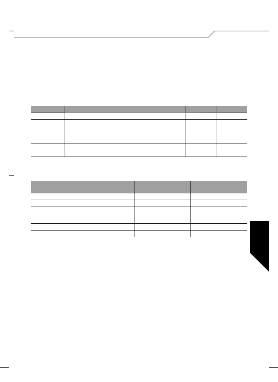
5. Programování parametrů regulátoru bez programátoru
Pro regulátor je možno naprogramovat 5 parametrů.
Do programovacího módu se dostanete následovně:
1. Zapojte regulátor podle schéma zapojení (kromě
zdroje napětí).
2. Zapněte vysílač a uveďte páku plynu do pozice Vpřed.
3. Zapojte k regulátoru zdroj napětí.
4. Regulátor potvrdí krátkým akustickým signálem.
5. Po cca 10 s se ozve dvojitý akustický signál pro
potvrzení úspěšného naprogramování pozice
VPŘED.
Typ parametru Pípnutí LED
Parametr 1 Typ článků 1 x 1 x
Parametr 2 Směr otáčení 2 x 2 x
Parametr 3 - brzda zapnuto/vypnuto - letadla
- Governor zapnuto/vypnuto - heli
- vzad zapnuto/vypnuto - auta
Parametr 4 Typ modelu letadla/vrtulníky 4 x 4 x
Parametr 5 Typ modelu auta/lodě 5 x 5 x
Pokud chcete parametry změnit, musíte pohnout pákou
plynu z pozice vpřed do pozice stop a v pozici stop musí
páka plynu setrvat minimálně po dobu 3 s.
Typ parametru LED svítí
Typ článků LiPo NiCD/NiMH
Směr otáčení Normal Reverse
Brzda - letadla
Governor - heli
Vzad - auta a lodě
Typ modelu (letadla/vrtulníky) letadla vrtulníky
Typ modelu (auta/lodě) lodě auta
Regulátor nyní průběžným akustickým pípákem a bliknutím LED diody signalizuje volbu parametru 1.
Volba parametru, který má být naprogramován, probíhá
pomocí následujících pohybů pákou plynu: krátká změna
polohy páky plynu z pozice vpřed na pozici stop a zpět na
pozici vpřed. Regulátor nyní dvojitým pípáním a blikáním
LED diody signalizuje volbu parametru 2.
Pro volbu parametru 3, 4 a 5 musí být výše popsaný postup proveden opakovaně.
3 x 3 x
Vlastní změna parametrů pak probíhá pomocí rychlé
změny pozice plynu z polohy stop do polohy vpřed a
zase zpět na stop.
pípák co 2 s
zapnuto
zapnuto
zapnuto
LED bliká
pípák co 0,5 s
vypnuto
vypnuto
vypnuto
CZ
Uložení změn se provádí změnou polohy plynu z pozice
STOP na pozici vpřed.
Ukončení a převzetí naprogramovaných nastavení se
uloží odpojením od zdroje napětí. Regulátor je naprogramovaný a připravený k provozu.
45
Page 46
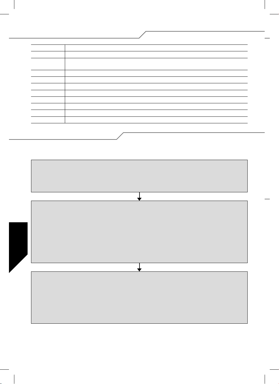
5.1. Vlastnosti a ochranné funkce
BEC Zdroj proudu přijímače
POR Ochrana proti spuštění motoru, zabraňuje nechtěnému spuštění motoru.
PCO Odpojení při příliš nízkém napětí, motor se u příliš prázdné baterie odpojí, aby byla dostatečná re-
hec Vysoký kmitočet impulzů pro citlivé magneticky šetrné řízení motoru.
SPS Super Programming System
Cool Power FET
WP Vodě odolný (Upozornění: vodě odolný neznamená vodotěsný).
Opto Galvanická separace mezi rušením motoru a přijímačem.
RX-Filter Vypne regulátor při neúplném nebo chybném signálu.
TOP Dvojitá ochrana proti přetížení
TP Teplotní pojistka
zerva kapacity pro řízení a zabránilo se podbití baterie (lze volit zda pro Nixx nebo Li-Poly články).
Tranzistory nové generace
5.2. Příklad programování
V následujícím příkladu je vysvětleno přizpůsobení regulátoru individuálním pozicím kniplů a následné programování
typu modelu: letadlo a zapnutá brzda.
Programování pozic kniplů
1. Zapněte vysílač a uveďte páku plynu do požadované pozice Vpřed.
2. Zapojte k regulátoru zdroj napětí (zazní krátký signál).
3. Po cca 10 s se ozve dvojitý akustický signál pro potvrzení úspěšného naprogramování pozice VPŘED.
4. Dejte páku plynu do pozice STOP, krátký akustický signál potvrdí úspěšnost naprogramování pozice STOP.
5. Odpojte zdroj napětí.
Programování parametrů regulátoru
1. Zapněte vysílač a uveďte páku plynu do pozice Vpřed.
2. Zapojte k regulátoru zdroj napětí (zazní krátký signál).
3. Po cca 10 s se ozve dvojitý akustický signál, po cca 3 s zazní akustický signál 3x.
4. Nyní se nachází regulátor v programovacím módu parametru 1. Pro potvrzení se průběžně rozsvítí LED
CZ
dioda a 1x zazní akustický signál.
5. Po čtyřnásobné změně polohy páky plynu z pozice vpřed do pozice stop a zpět do pozice vpřed,
se dostanete k parametru 4 (4x pípne a 4x za bliká).
6. Pro změnu parametru je nezbytné nejprve změnit polohu plynu z pozice vpřed do pozice stop.
Páka plynu musí setrvat minimálně po dobu 3s v pozici stop.
7. Zvolte mód letadla (AIR). Dioda svítí a akustický signál pípá co 2 s.
8. Ukládání probíhá změnou polohy páky plynu z pozice stop do pozice vpřed.
Nastavení brzdy u letadel
1. Po uložení parametrů (jak bylo výše popsáno) se regulátor nachází znova ve volbě parametru 4.
2. Čtyřnásobnou změnou polohu páky plynu z pozice vpřed do pozice stop a zpět do pozice vpřed se dostanete k volbě
parametru 3 (3x pípne akustický signál a 3x bliknou LED diody).
3. Pro změnu parametru musíte nejdříve změnit polohu páky plynu z pozice vpřed do pozice stop, ve které musí páka
plynu setrvat minimálně po dobu 3s.
4. Nyní je aktuálně znázorněna nastavená funkce brzdy Air Brake ON (LED bliká/signál pípá co 0,5 s) nebo Air Brake Off
(LED svítí/signál pípá co 2s). Popř. změňte parametr rychlou změnou polohy páky plynu z pozice stop do pozice vpřed a zpět.
5. Ukládání probíhá změnou polohy páky plynu z pozice stop do pozice vpřed.
6. Odpojte zdroj napětí.
46
Page 47
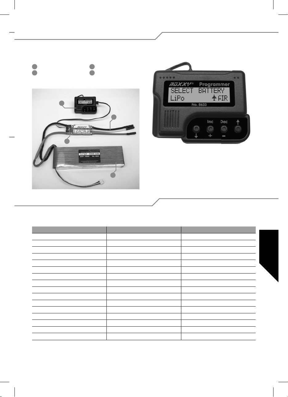
6. Nastavování pomocí programátoru
Pokud chcete regulátor nastavovat jednoduše a specifi cky pro modely, používejte programátor č. 31 8633. Přehledný
programátor Vám umožní rychlé a bezpečné nastavování přes LC displej.
1
Programátor
2
Zapojení motoru
1
3
3
Regulátor
4
Pohonná baterie
2
Navigace s programátorem
Obsluha programátoru je velmi jednoduchá. Pomocí tlačítek se šipkami – buď dolů nebo nahoru – přeskočíte
4
do programovacího modu Vaší volby. Kromě toho lze
pomocí šipek měnit typ modelu, a to tak, že podržíte obě
tlačítka stisknutá. Obě středové tlačítka DEC (–) a INC(+)
slouží k volbě popř. změně nastavení.
6.1. Přehled možností programování
Až na malé rozdíly jsou v podstatě všechny programovácí body stejně řazeny. Pro lepší porozumění uvádíme krátký
přehled programovacích možností ve formě tabulky.
Heli
Select Battery (typ článků)
Cut Off Voltage (odpojovací napětí)
Cut Off Type (typ odpojení motoru)
Motor Direction (směr otáčení motoru)
Advance Timing (časování motoru)
Acceleration (zrychlení)
Start Power
Response of Governor
Governon On/Off (regulátor zap./vyp.)
Motor pole Num (počet závitů motoru)
Gear Ration (redukce)
Max. RPM (max. otáčky)
Average RPM (průměrné otáčky)
Data Down Load (zápis dat)
Restore Mem. (čtení naprogram. dat)
Backup Mem. (záložní kopie)
Boot/ Car - Lodě/Auta Air (Letadla)
Select Battery (typ článků) Select Battery (typ článků)
Cut Off Voltage (odpojovací napětí) Cut Off Voltage (odpojovací napětí)
Cut Off Type (typ odpojení motoru) Cut Off Type (typ odpojení motoru)
Motor Direction (směr otáčení motoru) Motor Direction (směr otáčení motoru)
Advance Timing (časování motoru) Advance Timing (časování motoru)
Acceleration (zrychlení) Acceleration (zrychlení)
Start Power Start Power
Funkce Reverse Air Brake Type (typ brzdy)
Motor pole Num (počet závitů motoru) Airbrake On/Off (brzda zapnuto/vypnuto)
Gear Ration (redukce) Motor pole Num (počet závitů motoru)
Max. RPM (max. otáčky) Gear Ration (redukce)
Average RPM (průměrné otáčky) Max. RPM (max. otáčky)
Data Down Load (zápis dat) Average RPM (průměrné otáčky)
Restore Mem. (čtení naprogram. dat) Data Down Load (zápis dat)
Backup Mem. (záložní kopie) Restore Mem. (čtení naprogram. dat)
Backup Mem. (záložní kopie)
CZ
47
Page 48
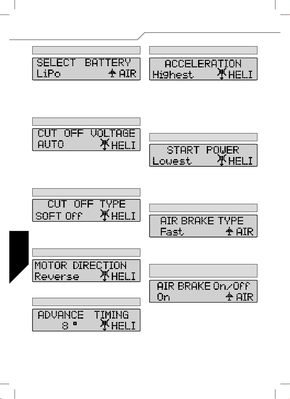
7. Podrobnosti k programování
1. Battery Type (typ baterií)
Pokud chcete nastavit požadovaný typ článků, použijte tlačít-
ko DEC nebo INC. Poté, co jste zvolili jiný typ článků se může
stát, že se všechny nastavené parametry v oblasti „CUT OFF
VOLTAGE“ (odpojovací napětí) a „CUT OFF TYPE“ (Vypnout
motor-typ) změní. Tyto módy lze nastavit tlačítky DEC a INC.
AIR - letadla.
2. Cut Off Voltage (odpojovací napětí)
Cut Off Voltage (odpojovací napětí) se řídí podle naprogramovaného typu baterií. U Li-Poly článků v automatickém
módu se regulátor odpojí u 3V/čl., u NiCd článků ovšem už
při 5,5V/čl. (typ odpojení lze nastavit). Pomocí tlačítek DEC
a INC můžete hodnotu sami nastavit. K dispozici je rozmezí
4,5V – 33,0V.
3. Cut Off Type (typ odpojení motoru)
V Cut Off Type (typ odpojení motoru) můžete nastavit typ
odpojení motoru při nízkém napětí. Můžete zvolit mezi „Soft
CZ
Off“ a „Hard Off“. Módy lze nastavit opět pomocí tlačítek DEC
a INC.
4. Motor Direction (směr otáčení motoru)
6. Acceleration (zrychlení)
V módu Acceleration (zrychlení) se nastavuje, jak rychle regulátor naběhne na maximální hodnotu. Toto je důležité, když
se funkce plynu ovládá spínačem, aby se stanovilo zpoždění,
jak rychle se přepne na „plný plyn“.
Příklad: Lowest / nejmenší zrychlení anebo Highest / nejvyšší zrychlení.
Nastavitelné parametry:
Lowest / Low / Normal / High / Highest (velmi nízký / nízký /
normální / vysoký / velmi vysoký). Obsluha klávesami DEC a INC.
7. Start Power
V menu Start Power se nastavuje rozběhový výkon (silový
moment), se kterým se motor rozbíhá (z klidu). Zejména při
provozu ve vrtulnicích se musí volit nízké hodnoty, aby se
chránilo ozubené kolo. Nastavovat lze Lowest / Low / Normal / High / Highest (velmi nízký / nízký / normální / vysoký /
velmi vysoký).
8. Air Brake Type (typ brzdy motoru) pouze u letadel
V módu pro letadla je možné nastavit funci brzdy a tím určit, jestli se motor bude zastavovat „měkce“ nebo „natvrdo“.
Pomocí tlačítek DEC a INC lze zvolit módy Slow / Normal /
Fast – pomalu / normál / rychle (měkce / normal / natvrdo).
V módu Motor Direction (směr otáčení motoru) se můžete
rozhodnout mezi běžným a obráceným směrem otáčení motoru.
5. Advance Timing (časování motoru)
Advance Timing (časování motoru). Jedná se o fázové posunutí točivého elektromagnetického pole mezi rotorem a
statorem. Obecně je pro většinu motorů vhodných 8°. Pokud
chcete nastavit pro nějaký motor speciální Setup, doporučujeme
následující hodnoty: 0-10°C pro Inrunner motory, 15-25° pro
Outrunner motory.
48
9. Airbrake On/Off (brzda motoru zap./vyp.) pouze
u letadel
V tomto bodě menu je možno volitelně nastavit zapnutou
nebo vypnutou brzdu.
Page 49
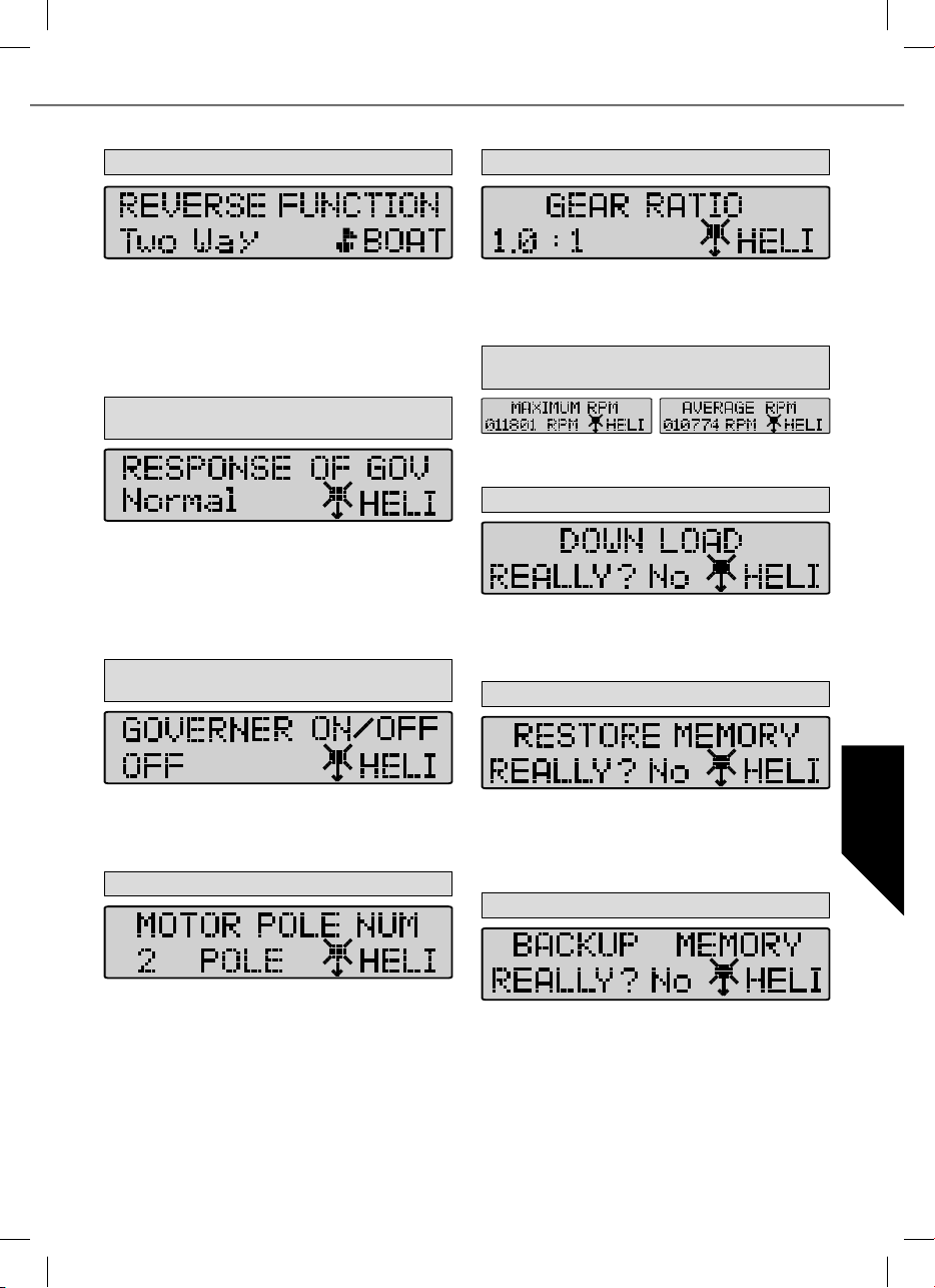
10. Funkce Reverse (pouze u lodí a aut)
14. Gear Ratio (redukce)
Pomocí funkce reverse lze u lodí a aut zvolit, zda bude motor
pracovat pouze jednosměrně nebo obousměrně. V módu
„One Way“ (jeden směr) je směr chodu motoru pevně dán
dopředu nebo dozadu. V „Two Ways Módu“ je motor nastaven
na provoz dopředu a dozadu.
Pozor! Nastavení mohou být zrušena při změně směru otá-
čení motoru (Motor Direction).
11. Response of Governon (charakteristika regulace)
–
pouze u vrtulníků
V tomto módu se nastavuje charakteristika regulace otáček.
Volitelně jsou k dispozici: Lowest / Low / Normal / High /
Highest – velmi pomalý / pomalý / normální / rychlý / velmi
rychlý. Pozor! Čím rychlejší hodnotu zvolíte, tím více proudu
bude akumulátor potřebovat! Pokud chcete regulátor popř.
baterie šetřit a prodloužit dobu letu, zvolte pomalejší nastavení.
12. Governon On/Off (regulátor zap./vyp.) pouze
u vrtulníků
V tomto menu lze nastavit vypnutí nebo zapnutí regulátoru.
Ten stabilizuje přeprogramovaný počet otáček a více méně je
konstantně drží. Mód On (zapnuto) pro stabilizované ot. nebo
Off (Vypnuto) pro nestabilizované.
13. Motor Pole Number (počet závitů)
V této úrovni nastavení lze zadávat individuální poměry pře-
vodu. V závislosti na počtu závitů a redukci převodovky se
vypočítá hodnota počtu otáček. Nastavitelné hodnoty vychází
od 1,0 : 1 až 25,0 :1.
15. Max. RPM & Average RPM
(max. otáčky/průměrné otáčky)
Tento mód udává maximální a průměrný počet otáček posledního letu s ohledem na nastavené hodnoty od bodu 14 a 15.
16. Down Load (zápis dat)
Pomocí Down Load se nastavené hodnoty zapisují do regulátoru. Tlačítkem DEC spustíte ukládání dat, programátor
každou sekundu pípne dokud není zápis ukončen. Pokud
chcete proces přerušit, stiskněte tlačítko INC.
17. Restore Memory (čtení naprogram. dat)
CZ
Pomocí Restore Memory otevřete uložené hodnoty, které
byly uloženy do vlastí paměti programátoru. Tlačítkem DEC
čtení dat spustíte, programátor každou sekundu pípne, dokud
není čtení ukončeno. Pokud chcete proces přerušit, stiskněte
tlačítko INC.
18. Backup Memory (záložní kopie)
V módu Motor Pole Number můžete nastavit kolika závity
motor disponuje. Tato hodnota je důležitá kvůli přesnému údaji
o počtu otáček. Nastavitelná hodnota: 2 – 36 závitů.
V Backup Memory uložíte nastavené hodnoty do paměti v
programátoru. Tlačítkem DEC ukládání dat spustíte, programátor každou sekundu pípne, dokud není ukládání ukončeno.
Hodnoty nastavené na regulátoru přitom zůstanou nezmě-
něny. Pokud chcete proces přerušit, stiskněte tlačítko INC.
49
Page 50

50
Page 51

51
Page 52

Irrtum und technische Änderungen vorbehalten
Copyright Multiplex Modellsport 2015
Kopie und Nachdruck, auch auszugsweise, nur mit
schriftlicher Genehmigung der
Multiplex Modellsport GmbH & Co.KG
Con riserva di modifiche tecniche o eventuali errori.
Copyright Multiplex Modellsport 2015
La copia e la ristampa, anche parziali, sono
consentite solamente sotto autorizzazione della
Multiplex Modellsport GmbH & Co.KG
Errors and omissions excepted.
Technical modifications reserved.
Copyright Multiplex Modellsport 2015
Duplication and copying of the text, in whole or in part,
is only permitted with the prior written approval of
Salvo errores o modificaciones técnicas.
Copyright Multiplex Modellsport 2015
Queda prohibida la reproducción total o parcial de este
documento, excepto con autorización por escrito de
Multiplex Modellsport GmbH & Co. KG.
Multiplex Modellsport GmbH & Co.KG
Sous réserve d‘erreur d‘impression et de
modification technique
Copyright Multiplex Modellsport 2015
La copie et la reproduction, même partielles,
sont soumises à l‘autorisation écrite de la Sté
Multiplex Modellsport GmbH & Co.KG
MULTIPLEX Modellsport GmbH & Co. KG neručí za
tiskové chyby a opomenutí. Vyhrazuje si rovněž právo na
technické změny bez předchozího upozornění.
Copyright Multiplex Modellsport 2015
Šíření a kopírování tohoto textu jako celku nebo jeho
části je možné pouze s předchozím písemným souhlasem
MULTIPLEX Modellsport GmbH & Co. KG.
Multiplex Service: +49 (0) 7252 - 5 80 93 33
MULTIPLEX Modellsport GmbH & Co.KG · Westliche Gewerbestr. 1 · 75015 Bretten · Germany · www.multiplex-rc.de
 Loading...