

Page 1
Industrial Insulation
Process Manual
Industrial & Mechanical Installation Guidelines
Page 2
Overview: ROXUL® Industrial Insulation Solutions
1.2 Insulation of piping 23 1.6 Insulation of boilers 67
1.2.1 Insulation with pipe sections 29 1.6.1 Insulation of fire tube boilers 67
1.2.2 Insulation with pipe wraps (mats) 31
1.2.3 Insulation with wired mats 33
1.2.4 Insulation support 34
1.2.7 Insulation of valves and flanges 40
1.2.8 Insulation of pipe elbows and T pieces 42
1.2.9 Reducers 43
1.2.10 Expansion joints 44
1.2.5 Cladding 36
1.2.6 Pipe hangers and pipe support 39
1.2.11 Tracing 45
1.2.12 Foot traffic 46
Page 3
1.3 Insulation of vessels 47
1.4 Insulation of columns 53
1.6.2 Supercritical steam generators 69
1.5 Insulation of storage tanks 59
1.7 Insulation of flue gas ducts 75
1.8 Cold boxes 82
Page 4

Contents
1. System solutions 7
1.1 Planning and preparation 11
1.2 Insulation of piping 23
1.3 Insulation of vessels 47
1.4 Insulation of columns 53
1.5 Insulation of storage tanks 59
1.6 Insulation of boilers 67
1.7 Insulation of flue gas ducts 75
1.8 Cold boxes 82
2. Theory 85
2.1 Norms & Standards 88
2.2 Product properties & test methods 107
2.3 Bases for thermal calculations 120
3. Tables 127
3.1 Units, conversion factors and tables 130
3.2 Product properties insulation and cladding materials 146
3.3 Usage tables 149
4. Products 169
ProRox® PS 960NA 171
®
ProRox
ENERWRAP® MA 960
ProRox® SL 920
ProRox® SL 930
ProRox® SL 940
ProRox® SL 960
ProRox® SL 540
ProRox® SL 560
ProRox® SL 590
ProRox® SL 430
ProRox® SL 450
ProRox® SL 460
ProRox® SL 760
ProRox® FSL 920
ProRox® FSL 930
ProRox® FSL 940
ProRox® FSL 960
ProRox® MA 930
ProRox® MA 940
PS 980
NA
NA
NA
NA
NA
NA
NA
NA
NA
NA
NA
NA
NA
NA
NA
NA
NA
NA
NA
ProRox® GR 903
®
ProRox
ProRox
LF 970
®
Rocktight
Page 5
ROXUL® insulation provide superior thermal and
acoustical performance and are fire resistant, water
repellent, non-corrosive and resistant to mold.
Specialists often willingly turn to our products
and expertise in industrial and marine & offshore
insulation. We have now packaged that expertise into
a practical guide: the 'ProRox® insulation Process
Manual‘.
This manual offers a transparent overview of
our ProRox® product range, including thermal,
fire-resistant, compression, comfort/multi-purpose,
fabrication and acoustic insulation solutions for
technical installations in the process & power
generation industries.
The Process Manual is a convenient resource tool
with relevant information at your finger-tips. Fold-out
sections take you directly to the right page, whether
you are looking for straight forward piping insulation
or more complex applications for columns, tanks and
boilers. In addition to pictures and photographs, a
range of tables and diagrams are included.
The ROXUL Process Manual is a helpful tool for
the application of our ProRox® industrial insulation
solutions in a process environment. Should you need
any further information about a specific application,
procedure or practical problem, please consult
www.roxul.com or contact your local ROXUL
representative at 1 800 265 6878.
2
Page 6
ROXUL
®
Industrial Insulation
ROXUL an independent organization with the
ROCKWOOL Group - is a leading supplier of high
quality stone wool products in the industrial
insulation market. With the ProRox® & SeaRox®
lines for the industrial market and for the marine &
offshore industry, our experts provide a full range of
products and systems for the thermal, acoustic and
firesafe insulation of industrial installations. ROXUL
continuously monitors the market developments.
Our 75+ years of global experience is reflected
in a complete set of high-grade products and
expert advice. Today, we remain fully committed to
providing the very best service in the market and a
total range of cutting-edge insulation solutions.
3
Page 7

The ROXUL® Industrial
Insulation Process Manual
Know-how for designers, engineers, site supervisors and managers of
industrial plants
Energy keeps the world in motion. Without it,
everything would come to a standstill. The global
economy is dependent upon a secure & efficient
supply of energy. Over eighty percent of the energy
currently being consumed is obtained from nonrenewable resources. Those resources are becoming
increasingly scarce, while at the same time the
demand for energy is exploding. This means that
owners, designers and operators of large, industrial
plants are challenged with the task of reducing their
energy consumption as much as possible in order to
ensure the long term sustainability of their operations.
Solar energy is just one of the possible alternatives.
Through, for example, solar power plants we
already succeed in converting concentrated sunlight
very efficiently into electricity. And this is just one
of the solutions that can help us drive down fuel
consumption and carbon emissions.
On top of that, insulation significantly reduces the
energy needed to manufacture a product or provide
a service. Also, new technologies for emission
controls at existing fossil burning facilities is greatly
enhanced by insulation. Nowadays there are a variety
of efficient insulation systems that enable scarce
energy reserves to be put to the best possible use.
The ROXUL Industrial Insulation Process Manual
illustrates these systems both theoretically and
practically. This process manual targets designers,
engineers, installers and managers of industrial
plants and provides an overview of the modern
insulation techniques for, by way of example, chemical
or petrochemical installations and power generation
facilities. Based on current standards and regulations
the manual provides accessible, practical guidelines
for the implementation of numerous insulation
applications.
Restriction of thermal losses to an absolute minimum,
including during transfer or storage, can considerably
reduce the energy consumption of industrial plants.
This also results in a reduction in carbon dioxide
(CO²) emissions, which are created each time fossil
fuels such as coal or gas are burnt and which, as a
greenhouse gas, is responsible for the global increase
in temperature.
From an environmental perspective, adequate
insulation of industrial plants is a significant means of
reducing (CO²) emissions.
4
Page 8

In addition, the right insulation keeps temperatures,
for example in pipes and storage tanks, within
strict tolerances, thereby ensuring reliable process
efficiency. At the same time, adequate insulation
protects the plant itself. Modern insulating materials
can thoroughly protect plant components from
moisture and associated corrosion. Installation
and process maintenance costs can be reduced
considerably and the effective lifetime ofindustrial
plants can be successfully maximized.
Furthermore, industrial insulation also provides
a significant contribution to personnel protection.
Optimum insulation reduces process temperatures
and noise in the industrial environment to an
acceptable level, to the limits generally regarded
in the industry to be those required for a safe and
comfortable working environment.
With a complete range of techniques and insulation
systems, ROXUL® offers designers, engineers and
construction supervisors optimum tailored solutions
for the petrochemical, power generation, ship
building, offshore and processing industries.
In the 'Flow of Energy' diagram on the following
page, you will find an overview of all of the sectors
in which ROXUL is active. All of our ProRox® (and
SeaRox®) products, such as pipe sections and boards
(slabs) are designed to meet the highest quality and
safety standards and comply with the strictest, and
therefore safest, fire safety classes. Stone wool is
non flammable, non combustible and can withstand
temperatures up to 2150 °F (1177 °C) and therefore
provides a crucial contribution towards passive fire
protection.
As a supplement to this process manual, ROXUL
also regularly provides infor mation about technical
innovations, product solutions and recent and
relevant documents available online at our website
www.roxul.com. NOTE: The process manual is a
guideline and can only provide general advice for
specific instances in the field of plant and processes.
For these instances, the ROXUL Technical Services
Team is available to provide advice during the design,
engineering and implementation phases. Please find
our contact details on the back cover of this manual.
5
Page 9
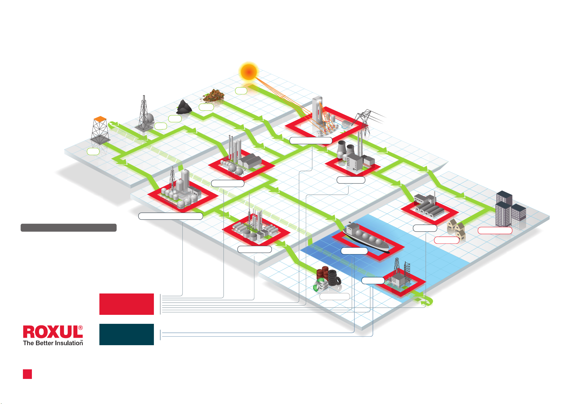
ROXUL® Industrial Insulation, Flow of Energy
Exploration, drilling and production
Sun
Waste
Coal
Gas
Oil
Flow of energy
Business Areas:
ProRox® insulation for industry:
Our ProRox® product line covers all our thermal, fire-resistant,
compression, comfort/multi-purpose, fabrication and acoustic
insulation solutions for industrial installations in the process
industry.
®
insulation for shipbuilding and offshore:
SeaRox
SeaRox® comprises the full marine and offshore product line.
This sharp focus enables us to combine our expertise and
extensive experience like never before to develop outstanding
insulation solutions for our customers.
ProRox
Petroleum Rening Processing
®
Gas Processing
Petrochemicals
Solar Power Plant
Power Plant
End Products
Marine
Oshore
Processing industry
Industrial
Residential
Consumption
Non-residential
SeaRox
®
6
Page 10
System solutions
Industrial insulation
System
solutions
1
Page 11

Page 12

1. System solutions
Table of contents
1.1 Planning and preparation 11
1.1.1 Decision criteria for the design of an insulation system 11
A. Functional requirements 12
B. Safety aspects 16
C. Economics 17
D. Environmental 18
E. Corrosion Prevention 18
1.1.2 Design & planning of the insulation work 19
1.1.3 Corrosion prevention 19
1.1.4 Storage of insulation materials 22
1.2 Insulation of piping 23
1.2.1 Insulation with pipe sections 29
1.2.2 Insulation with pipe wraps (mats) 31
1.2.3 Insulation with wired mats 33
1.2.4 Insulation support 34
1.2.5 Cladding 36
1.2.6 Pipe hangers and pipe supports 39
1.2.7 Insulation of valves and flanges 40
1.2.8 Insulation of pipe elbows and Tpieces 42
1.2.9 Reducers 43
1.2.10 Expansion joints 44
1.2.11 Tracing 45
1.2.12 Foot traffic 46
1.3 Insulation of vessels 47
1.4 Insulation of columns 53
1.5 Insulation of storage tanks 59
1.6 Insulation of boilers 67
1.6.1 Insulation of fire tube boilers 67
1.6.2 Supercritical steam generators 69
1.7 Insulation of flue gas ducts 75
1.7.1 Installation of the insulation systems for flue gas ducts 75
1.7.2 Cladding of flue gas ducts 78
1.7.3 Acoustic insulation of flue gas ducts 81
1.8 Cold boxes 82
9
Page 13

Notes
10
Page 14

1. System solutions
1.1 Planning and preparation
preparation
Planning and
The design of a suitable insulation system for
industrial installations is a major factor for its
economical operation, functionality, security,
durability and environmental impact. Additionally,
the installation-specific heat losses are specified
for the entire life cycleof the plant. Corrections at
a later stage, such as subsequently increasing the
thickness of the insulation, for example, may no
longer be possible due to lack of space. Corrections at a later stage may also entail a far greater
investment compared to the original planning.
Continually rising energy costs are also often
overlooked factors when dimensioning the
insulation. Insulation thicknesses that are
designed to last take energy price increases into
account. They form an important criterion for the
economical operation of the installation after just
a few years.
Properly dimensioned insulation systems
constitute an important contribution to
environmental protection, carbon dioxide (CO²)
reduction and to economic success. CO² reduction
is also an economical operation, as it lowers the
costs for CO² emission certificates.
Nowadays, conservational and economical
operations are no longer conflicting ideas, but are
two inseparable parameters.
1.1.1. Decision criteria for the design of
an insulation system
Selecting a suitable insulation system depends on
the following five parameters:
1. Functional requirements
a. Object dimensions
b. Operation of the installation
c. Operating temperatures
d. Permissible heat losses or temperature
changes ofthe medium
e. Frost protection
f. Ambient conditions
g. Maintenance and inspection
2. Safety aspects
a. Personal protection
b. Fire protection
c. Explosion prevention
d. Noise reduction within the plant
3. Economics
a. Economical insulation thickness
b. Pay-back time
4. Environment
5. Corrosion prevention
11
Page 15
1.1 Planning and preparation
A. Functional requirements
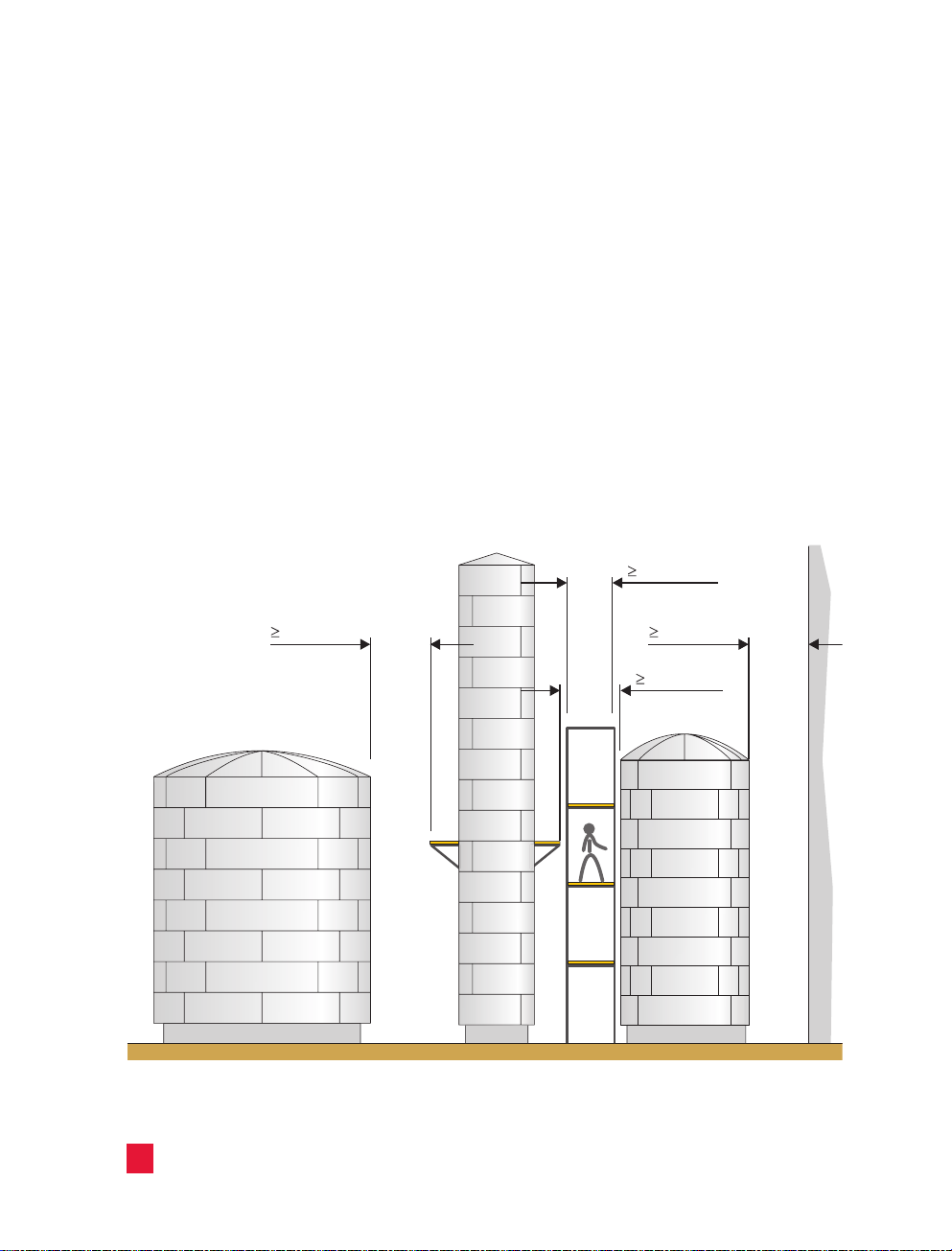
a) Object dimensions
The space requirements of the insulation must be
taken into account when the installation is being
designed and planned. Therefore, the insulation
thicknesses should be determined in the early
planning stages and the distances between the
individual objects should be taken into account in
the piping isometrics. To guarantee systematic
installation of the insulation materials and the
cladding without increased expense, observe the
minimum distances between the objects
asspecified in the following illustrations.
Minimum distances between vessels and columns; dimensions in inches (mm)
31.5” (800)
40” (1000)
40” (1000)
40” (1000)
12
Page 16
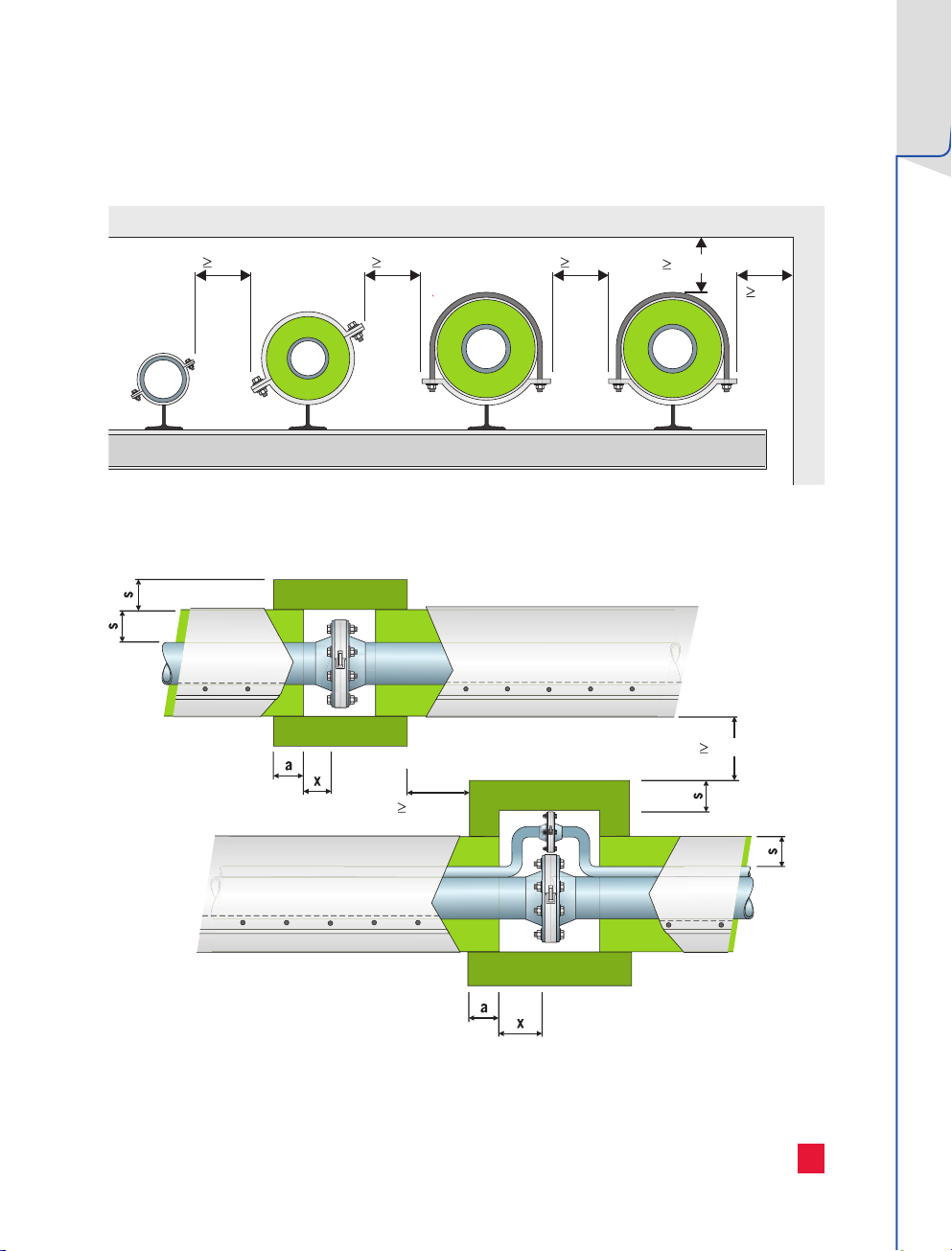
4” (100)
4” (100)
Minimum distances between insulated pipes; dimensions in inches (mm)
preparation
Planning and
4” (100) 4” (100) 4” (100)
Minimum distances within range of pipe flanges; dimensions in inches (mm)
4” (100)
4”
(100)
a = distance flange to normal insulation
a ≥ 2" (50 mm)
x = bolt length + 1.2" (30 mm)
s = insulation thickness
13
Page 17
1.1 Planning and preparation
A. Functional requirements
b) Operation of the installation
To select a suitable insulation system, the
operating method of the installation must be
considered. A basic distinction is made between
continuous and interrupted operation. With
continuous operation, the operating temperatures
are constantly above or constantly below the
ambient temperatures. The interrupted operating
method, also referred to as intermittent or batch
operation, is characterized by the fact that the
installation is switched off between each
operating phase and during that time can assume
ambient temperatures. For special applications,
e.g. dualtemperature systems, the operating
temperature alternates above or below the
ambient temperature.
c) Operating temperature
The appropriate insulation material should be
resistant to the intended operating/peak
temperatures. Thisproduct property is assessed
by the maximum service temperature (also see
Chapter 2.2 “Product properties & test methods”).
d) Permissible heat losses or temperature
changes ofthemedium
With many technical processes, it is essential that
media in vessels, columns or tanks do not fall
below a specific lower temperature limit,
otherwise chemical processes will not proceed as
intended or the media will set and can no longer
be pumped or extracted. Over-cooling can lead to
the precipitation of, for example, sulphuric acid in
exhaust and flue gas streams, which promotes
corrosion in the pipes or channels.
With flowing media, it is essential to ensure that
the temperature of the medium is still at the
desired level at the end of the pipe. The thermal
insulation is designed according to these
requirements. Under extreme conditions (e.g.
lengthy periods of storage, longtransport routes
or extreme temperatures), installing tracing may
be necessary, to ensure that the media is kept
within the required temperature limits.
Thermo-technical engineering calculation
programs like NAIMA's 3E Plus® or ROXUL's
"ROCKASSIST" (coming soon) can aid in ensuring
the optimum engineering and design of
these insulation systems. More information can be
found on our website www.roxul.com. For special
situations please contact the ROXUL® Technical
Services Team for further guidance.
Inside buildings, uninsulated or poorly insulated
parts of installations unnecessarily increase room
temperatures, which can have a negative effect on
the working environment - both for the people
who work long hours under these conditions and
for the electronic components. In addition to the
increased heat loss, the need for climate
controlled rooms requires further energy
consumption. The design of the insulation and the
related reductions in terms of heat loss from
parts of installations should be relevant to the
entire infrastructure and use of the building.
14
Page 18
e) Frost protection
Installations that are situated outside are at risk
from frost in the winter. In addition to the
malfunctioning of installations, installations also
risk damage caused by the expansion of frozen
water. Adequate measures against frost protection
are critical to protect the installation from
freezing. Insulation can reduce heat loss and aid
in frost protection. Insulation alone cannot
indefinitely prevent the installation from freezing.
Installing additional tracing may be necessary
between the object and the insulation. To prevent
freezing, the insulation must be designed so the
heat flow rate of the insulated object is less than
the heat provided by the tracing.
f) Ambient conditions
Select an insulation system that offers long-lasting
resistance to the surrounding environme nt.
Atmospheric influences: wind, rain
Mechanical loads such as vibrations or
foottraffic
Corrosive environment (proximity to sea,
chemicals,…)
an air space of at least 2/3” (15 mm) between the
insulation and the cladding, and create 0.4”
(10 mm) diameter ventilation and drain holes in
the covering at intervals at a maximum of 12"
(300 mm). If necessary, the insulation and
cladding must resist chemical influences that
develop within the environment.
Installations operating below ambient
temperatures have a high risk of moisture
condensing from the ambient air inside the
cladding. Use a continuous vapor retarder on
piping operating below ambient temperatures and
seal all joints, surfaces, seams and fittings to
prevent condensation (use of staples is not
recommended).
g) Maintenance and inspection
To avoid complicating routine maintenance and
inspection work unnecessarily, maintenanceintensive areas must be taken into account,
especially when designing the insulation work.
Removable insulation systems, such as removable
coverings and hoods, could be fitted in such areas,
for example. Easily removable covering systems
are also recommended for flanges and pipe
fittings. These coverings are generally fastened
with quick-release clamps, which can be opened
without special tools.
The insulation of fixtures such as flanges or pipe
fittings must be interrupted at a sufficient
distance to allow installation or dismounting to be
carried out. In this case, take the bolt length at
flange connections into consideration. Any fixtures
in the range of the insulation, including the
interruption in the installation, should be
insulated with removable coverings overlapping
the insulation and maintaining continuity across
the fixture.
preparation
Planning and
Moisture accumulation in insulation increases
thermal conductivity and the risk of corrosion of
the insulated installation components. Cladding
must be installed to prevent the ingress of
moisture into the system. If the ingress of
moisture into the insulation is unavoidable, retain
15
Page 19

1.1 Planning and preparation1.1 Planning and preparation
B. Safety aspects
a) Personal protection
Surface temperatures in excess of 140 °F (60°C)
can lead to skin burns, if the surface is touched.
Therefore, all accessible installation components
should be designed to protect personnel and
prevent injuries. The insulation applied to such
plant components must ensure that surface
temperatures in excess of 140 °F (60°C) do not
occur during operation. Consult our Technical
Services Team to determine the required
insulation thickness to aid in personnel
protection. All of the operational parameters must
be known to achieve a reliable design, including,
for example, the temperature of the object, the
ambient temperature, air movement, surface
materials, distance from other objects, etc.
NOTE
As the surface temperature depends on a set
of physical parameters, which cannot always
be calculated or estimated with any degree
of certainty, the surface temperature is not
a guaranteed measurement. If the required
protection (temperature) cannot be achieved
by insulation, apply additional protective
devices, such as safety guards or enclosement
of theobject.
companies and the operator.
As a basic principle, consider the fact that the fire
load in a building or industrial installation can be
considerably increased by flammable insulation
materials. On the other hand, non-flammable
insulation materials such as mineral wool (stone
wool), which has a melting point of >2150 °F
(>1,177 °C), not only have a positive impact on the
fire load, but in the event of a fire, also constitute
a certain fire protection for the installation
component.
b) Fire protection
The general fire protection requirements imposed
on structural installations are usually defined
within the local Building Codes or the
specifications of plant owner. Structural
installations must be designed, built, modified and
maintained to prevent the outbreak of a fire and
the spread of fire and smoke. In the event of a fire,
the rescuing of people and animals and effectively
extinguishing the fire must be made possible.
During the design of the installation, it is vital to
determine the nature and scope of the fire
prevention measures together with the building
supervisory board, the fire department, insurance
16
Installation components with tracing, in particular,
which use thermal oil as a heat transfer medium,
have an increased risk of catching fire in the event
of a leak. In this case, ensure that the thermal oil
cannot penetrate into the insulation material.
c) Explosion prevention
If there is a risk of fire and explosion, the surface
temperature of the object and the cladding must
be considerably lower than the ignition
temperature of the flammable substance and/or
gas mixtures. This requirement also applies to
thermal bridges, such as pipe mounting supports,
supporting structures and spacers etc.
With regard to insulation systems, explosion
Page 20
preparation
Costs
Planning and
protection can only be achieved with a doubleskin
covering. A doubleskin covering is a factory made
cladding that has been welded or soldered to
make it air proof and diffusion-resistant. In
addition special (local) explosion regulations must
be observed.
In explosive areas electrostatically charged
substances like unearthed cladding or nonconductive plastics must be grounded (earthed).
For further guidance please consult your local
safety guidelines relating to static electricity.
d) Noise protection
The guidelines for noise in the ordinance and
workplace are stated in the local regulations and
standards. Generally, the level of the guideline values
depends on the nature of the activity.
C. Economics
In the industry there are two grades of insulation.
The first grade focuses on reducing heat losses
and the prevention of injuries to people operating
or working nearby the installations. The second
grade of insulation, the so called “economical
insulation thickness” focuses on significant heat
loss reduction and as a result achieving a better
return on investment.
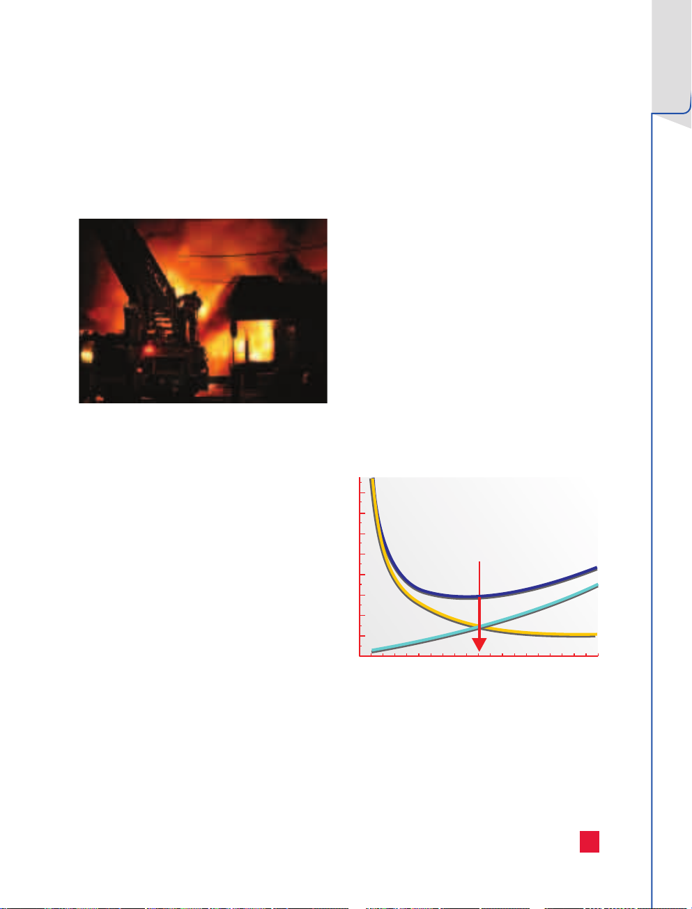
a) Economical insulation thickness
Insulation reduces the heat losses from the
object. Thethicker the insulation, the greater
theheat reduction and consequently, the more
energy is saved. However, the investment and
expenditure, e.g. for depreciation, interest rates
and higher maintenance costs also rise ifthe
insulation thickness is increased. At a certain
insulation thickness, the sum of the two cost flows
reaches a minimum. This value is known as the
economical insulation thickness. Aqualitative
curve of a similar costs function is shown below.
Economical
insulation
thickness
Total costs
The sound propagation of installation components
can be reduced using insulation systems. The
nature and effect of the sound insulation depend
onthe frequency and the sound pressure level.
Insulation costs
Heat loss costs
Insulation thickness
The energy costs cannot be based solely on the
current price. Developments over recent years
indicate energy costs will continue to rise.
17
Page 21
1.1 Planning and preparation1.1 Planning and preparation
C. Economics
Increasing energy prices are tending to bring
about a shift in economic insulation thicknesses
towards larger thicknesses.
b) Pay-back time
In addition to the economical insulation thickness,
another frequently used economical parameter is
the return on investment period (ROI), also
referred to as the payback period. This is defined
as the period within which the cost of the
insulation is recuperated through savings on heat
loss costs.
ROI period =
In the case of industrial insulation systems, the
return on investment period is generally very
short, often being much less than one year.
Considering only the return on investment period,
however, can be deceptive, as this approach
disregards the service life of the installation.
With long-life installations, it is advisable to select
higher insulation thicknesses, even if this means
accepting a longer return on investment period.
Throughout the entire service life of the
installation however, the increased insulation
thickness results in a significantly higher return
on the investment in insulation and achieves a
much more economic operation of the installation.
Costs of the insulation
annual saving
[a]
D. Environmental
The burning of fossil fuels, such as coal, oil or
gas, not only depletes the available primary
energy sources, but also, due to the emission of
carbon dioxide (CO²) into the atmosphere, places
aburden on the environment.
The increasing CO² concentration in the Earth’s
atmosphere plays a significant part in the global
increase in temperature, also referred to as the
“greenhouse effect”. CO² absorbs the thermal
radiation emanating from the earth’s surface
andin doing so reduces the dissipation of heat
into space. This is leading to a change in the
world’s climate with as yet inestimable
consequences. Reducing CO² emission can only
beachieved through more efficient management
of fossil fuels. Increasing the insulation
thicknesses is essential for the reduction of CO²
emissions.
Reducing CO² emissions also has a positive
financial benefit for businesses within the context
of an emissions trading scheme. The benefits of
increased insulation thicknesses in industrial
installations are twofold, as the costs for both
energy consumption and CO² emissions are
decreased.
E. Corrosion Prevention
See Chapter 1.1.3
18
Page 22
preparation
Planning and
1.1.2 Design & planning of the
insulation work
Requirements for insulation work must be
included in the design and construction phase of
industrial plants. It is advisable to involve all
project managers at an early stage to avoid
unnecessary issues or delays.
All preparatory works must be completed
according to the relevant insulation standards.
The following preconditions must be fulfilled:
If necessary, work has been carried out on the
object to protect against corrosion
Tracing and technical measurement equipment
have been installed
The minimum distance between the objects
hasbeen observed (see illustrations on pages
12and 13)
Surfaces have no coarse impurities
Mounting supports have been installed on the
object to accommodate the support structure
Collars and sealing discs have been fitted to
theobject
Taps on the object are long enough to ensure
that flanges lie outside the insulation and can
be screwed on without hindrance
Supports are designed so that insulation,
watervapor retarders and cladding can be
professionally installed
The insulation can be applied without any
obstacles (e.g. scaffolding)
Welding and bonding work has been carried out
on the object
The foundations have been completed
1.1.3 Corrosion prevention
Industrial facility disruptions are due to the lack
of, or inadequate forms of, protection against
corrosion. This considerably reduces the service
life of industrial plants, and more frequently,
essential shutdown or overhaul work impairs the
efficiency of the installation.
It is commonly, but wrongly, assumed that the
insulation system also protects an installation
against corrosion. For each installation it must be
determined whether protection against corrosion
is required and, if so, which are the appropriate
measures.
Generally, the design of the insulation system &
corrosion protection will depend on the following
parameters.
Operation of the installation
- Continuous operation
- Interrupted/intermittent operation
- Operation involving varying temperatures
- Type of plant (e.g. Petrochemical,
pharmaceutical, etc)
Operating and Ambient temperatures of the
installation
Metals and Materials Used
- Non-alloy or low-alloy steel
- Austenitic stainless steel
- Copper
External influences upon the installation
- Environment of the installation (chemically
aggressive?)
- Location
The best practices may vary per country and/or
standard. The design of corrosion protection is
often carried out on the basis of a small selection
of standards, such as ASTM C795, that do not
adequately take into account all the specific
features of protecting against corrosion in
insulation systems. For further details on
corrosion protection we recommend referring
NACE SP0198 and the ROXUL® Corrosion Under
Insulation (CUI) brochure.
19
Page 23

1.1 Planning and preparation1.1 Planning and preparation
1.1.3 Corrosion prevention
In the case of cold insulation, if the object is
made of non-alloy or low alloy steel, it must be
protected against corrosion.
In the case of objects made, for example, of
austenitic stainless steel or copper, the
installation must be tested in each individual
case by the planner to determine whether
protection against corrosion is necessary.
Objects made from austenitic stainless steel do
not require protection against corrosion if the
temperature never – even for a short period –
exceeds 120 °F (50 °C)
NOTE
Protection against corrosion should be applied
in the case of all installations made from
non-alloy or low-alloy steel where the
operating temperatures are below
250 °F (120 °C). Protection against corrosion
may be omitted in the case of:
Installations operating continuously under
extremely cold conditions [below -50 °F
(-50 °C)] such storage tanks.
Insulated surfaces of power plant
components, such as boiler pressure
components, flue gas and hot air ducts and
steam pipe systems with operating
temperatures that are constantly above
250 °F (120 °C).
If austenitic stainless steel is insulated with any
type of insulation - For temperatures of up to
930 °F (500 °C), aluminum foil of not less than
.06 mm thick to be applied to the steel surface,
arranged to shed water with overlaps of not less
than 2" (50 mm) at the joints.
CINI Manual “Insulation for industries”
CINI recommends applying corrosion protection
prior to the insulation work at any time.
In all phases, pay attention to CUI (corrosion
under insulation) prevention: design,
construction, paint & coating work, application
of the insulation system, inspection and
maintenance. Equipment and piping sections
like nozzles, supports etc. should be designed
and maintained to prevent ingress of water into
the insulation system.
The “paint” specifications are split up into:
-
Construction material
(carbon steel, stainless steel)
- Temperature ranges from -22 °F (-30 °C) to
1000 °F (540 °C) with special attention to the
temperature range between 0 °F (-20 °C) and
300 °F (150 °C).
The corrosion protection can be achieved using
aluminum foil wrapping, thermal sprayed
aluminum (TSA) or paint.
Protection against corrosion may be omitted in the
case of installations operating continuously under
extremely cold conditions [< -22 °F (-30 °C)]
Application
Before applying corrosion protection coating, the
surface must be free from grease, dust and acid
and, for better adhesion, the priming coat should
be roughened. Blasting is recommended as a
surface preparation method (with austenitic
stainless steel, use a ferrite free blasting
abrasive).
Observe the corresponding processing guidelines
of the coating manufacturer. If metals with
different electrochemical potentials, such as
aluminum and copper, come into contact with one
another, there is a risk of electrochemical
corrosion. If necessary, this can be avoided using
insulating, intermediate layers such as nonmetallic straps. The presence of moisture will
increase the development of electrochemical
corrosion.
20
Page 24
preparation
Planning and
The table further on this page, which has been
derived from the standard DIN 4140, indicates the
initial risks of electrochemical corrosion in cases
where various combinations of metals are used.
Electrochemical Corrosion Potential
Material Combination material
Metal
Zinc
Aluminum
Ferritic steel
Lead
Austenitic stainless
steel
Copper
Surface ratio in proportionto
combinationmaterial
Small - M M H H H
Large - L L L L L
Small L - L H H H
Large L - L M L H
Small L L - H H L
Large L L - L L L
Small L L L - H H
Large L L L - M M
Small L L L L - M
Large L L L L - L
Small L L L L L -
Large L L L L L -
Zinc Aluminum
NOTE
The table does not take into account forms
ofcorrosion with other root causes, such as
stress corrosion. For further information, see
Chapter 2.2 “Product properties & test
methods” – AS-Quality on page 115.
Ferritic
steel
Lead
Austenitic
stainless
steel
Copper
L - Light or little corrosion to material
M - Moderate corrosion to material, for example, in very humid atmospheres
H - Heavy electrochemical corrosion to material
Observation: The table shows the corrosion of the “material”, and not that of the “combination material”.
“Light” means: “small-scale in proportion to the combination material”, “heavy” means: “large-scale in
proportion to the combination material”.
Example 1: Material is a zinc galvanized screw in combination material, a cladding made from austenitic
stainless steel: Row “zinc small”: “H” – heavy corrosion of the screw.
Example 2: Material , a cladding made from austenitic stainless steel screwed on with a screw galvanized
with combination material zinc: Row “austenitic stainless steel large”. “L” – the corrosive attack upon the
austenitic steel is light.
21
Page 25

1.1 Planning and preparation
1.1.4 Storage of insulation materials
Incorrect storage of insulation materials outdoors
can cause insulation to deteriorate. Insulation
should be protected when stored, during
installation and when fitted to minimize moisture
exposure, physical damage and contamination. If
storage indoors is not possible, protect the
insulation material from weather influences by
covering it with waterproof material. Insulation
should also be stored a minimum of four inches
above ground and kept on a solid surface away
from ponding water and ground moisture.
Moisture causes many types of corrosion that
virtually never develop in a dry system. The major
types of corrosion in relation to insulation
technology are oxygen, electrochemical and stress
corrosion. Insulation materials that are
manufactured with properties (such as low
chloride content or added inhibitors) can
irrevocably lose these properties when exposed to
contamination or additives are leached out.
The thermal conductivity of water is approximately
25 times greater than that of air. An increase in
moisture therefore results in an increase in the
thermal conductivity of the insulation and,
correspondingly, a decrease in the insulation
efficiency. Higher moisture can also mean a
significantly higher weight, which, as a rule, is not
taken into account in the static design of an
insulation system. It is therefore important to
protect the insulation from moisture after
installation, as well as ensure insulation is
thoroughly dry when installed (especially in sealed
application at low temperatures or where the
temperature cycles).
22
Page 26
1. System solutions
1.2 Insulation of piping
Piping plays a central role in many industrial
processes in chemical or petrochemical
installations such as power plants, as it connects
core components such as appliances, columns,
vessels, boilers, turbines etc. withone another
and facilitates the flow of materials andenergy.
Toguarantee a correct process cycle, the
condition of the media within the pipes must
remain within the set limitations (e.g.
temperature, viscosity, pressure, etc.). In addition
to the correct isometric construction and
fastening of the piping, the piping insulation also
has an important function. It must ensure that
heat loss are effectively reduced and that the
installation continues to operate economically and
functionally on a permanent basis. This is the only
way to guarantee the maximum efficiency of the
process cycle throughout the design service life
without losses as a result of faults.
Requirements for industrial piping
The basic efficiency and productivity factors of
piping for the processing industry include: energy
efficiency, dependability and reliability under
different conditions, functionality of the process
control, appropriate support structure suitable for
the operating environment, as well as mechanical
durability. The thermal insulation of piping plays a
significant role in fulfilling these requirements.
Thermal insulation
The functions of proper thermal insulation for
piping include:
Reduction of heat losses (cost savings)
Reduction of CO² emissions
Frost protection
Process control: ensuring the stability of
theprocess temperature
Noise reduction
Condensation prevention
Personnel protection against high temperatures
ProRox® products for pipe insulation
ROXUL Inc offers a wide range of high-quality stone
wool insulation products for the insulation of
industrial plants. These products are part of our
extensive ProRox® range for industrial insulation.
With this specific field of application in mind we
developed our pre-formed pipe sections and pipe
wrap (mat) products for pipe insulation. All these
products are easy to install and contribute to a high
level of efficiency, functionality and reduced heat
losses. Continuous internal and external inspection
and high levels of quality assurance ensure the
consistently high quality ofall ROXUL® products.
The examples of use below cannot fully take into
account the particular circumstances of the
construction-related factors. Determine whether
the products are suitable for the corresponding
application in each individual case. If in doubt,
consult the ROXUL Technical Services Team.
The applicable standards and regulations must
also be observed. A few examples follow:
NACE SP0198 (Control of corrosion under
thermal insulation and fireproofing materials - a
systems approach)
MICA (National Commercial & Industrial
Insulation Standards)
DIN 4140 (Insulation works on technical
industrial plants and in technical facility
equipment)
AGI Q101 (Insulation works on power plant
components)
CINI-Manual “Insulation for industries”
BS 5970 (Code of practice for the thermal
insulation of pipework, ductwork, associated
equipment and other industrial
installations)
of piping
Insulation
23
Page 27
1.2 Insulation of piping
Hot insulation systems
Principally, a thermal insulation structure for
piping consists of an appropriate insulating
material, usually covered by sheet metal cladding.
This protects the object and the insulation from
external influences such as the weather and
mechanical loads. Spacers are also essential with
insulation such as wired mats, which do not offer
sufficient resistance to pressure to hold the
weight of thecladding and other external loads.
These spacers transfer the cladding loads directly
onto the object. In thecase of vertical piping,
support structures are fitted totake on the loads
of the insulation and the cladding. Ingeneral,
support structures and spacers form thermal
bridges.
Selecting a suitable insulation system depends on
numerous parameters. These are described in
greater detail in Chapter 1.1. Regarding the
different forms of pipe insulation, a fundamental
distinction can be drawn between the following
insulation systems.
Insulation with pipe sections
Generally, the best insulation is achieved using
ProRox® Pipe Sections and can be used up to
temperatures of 1400 °F (760 °C) when using
ProRox® PS 980NA Type V insulation. They are
supplied ready split and hinged for quick and easy
snap-on assembly and are suitable for thermal
and acoustical insulation of industrial pipe work.
Due to their excellent fit and high compression
resistance, pipe sections can often be applied in
asingle layer without any additional spacers.
If multiple layers are required, ROXUL® can also
supply double layered - ‘nested’ - pipe sections.
This reduces installation costs considerably. Also
the number of thermal bridges, which have a
negative influence on the insulation, is greatly
reduced, while a lower thickness may be applied
compared to wired mats.
Using pipe sections for the insulation of pipes
results in considerably reduced installation time
and costs. The lack of spacers and “unforeseen”
gaps minimizes heat losses and the risk of
personal injuries due to hot spots on the cladding.
At temperatures above 550 °F (300 °C), the
provisional application of spacers must be
determined in each individual case.
Pipe sections are always precisely tailored to the
corresponding pipe diameter to minimize the risk
of convection and processing defects. ROXUL pipe
sections are available in diameters of
NPS 1/2" (23 mm) to NPS 28" (713 mm).
Insulation with load-bearing pipe wraps
(mats)
Load-bearing pipe wraps (mats), such as
ENERWRAP® MA 960NA are the latest development
in the insulation sector. ENERWRAP® MA 960NA is
a stone wool (mineral wool) insulation wrap
available with a black mat or reinforced foil facing
and is designed for easy installation of large
diameter pipes. Typical applications include:
pipe diameters >NPS 12" (326 mm), or;
piping with a high number of shaped pieces
such as elbows or T-joints.
ENERWRAP® MA 960NA can be applied up to
temperatures of 1200 °F (650 °C). It is highly
compression resistant and can be applied without
any additional spacers.
24
Page 28
Consequently the number of thermal bridges,
which have a negative influence on the insulation,
is greatly reduced.
Pipe insulation with wired mats has been a
time-tested universal solution for many decades
now. Due to their flexibility and high temperature
resistance, wired mats can be easily cut and
mounted onto piping. Wired mats are ideal for
application in situations where the use of pipe
sections or load bearing wraps (mats) is difficult
or impossible. Historically this included large
diameter pipes and high temperatures (where the
wired mat provided structural integrity to the
insulation at high temperatures), but advanced
modern ProRox® pipe section and ProRox® pipe
wraps (mats) have provided a suitable alternative
to wired mats. Wired mat is still used today in
piping with a high number of shaped pieces such
as elbows or T-joints.
Wired mats have a relatively low resistance to
pressure and from a practical point of view should
only be mounted in combination with spacers or
support structures. Because of the resulting
thermal bridges, better insulation performances
are often achieved in thelower and middle
temperature range [up to 550 °F (300 °C)] with
pipe sections or load bearing wraps (mats).
of piping
Insulation
The result is considerably reduced installation
time and costs. The lack of spacers and
“unforeseen” gaps minimizes heat losses and the
risk of personal injuries due to hot spots on the
cladding.
corresponding length of the pipe circumference
on site and are fastened with clamps.
Pipe wraps (mats) are tailored to the
Insulation with wired mats
Wired mats, are lightly bonded stone wool wraps
(mats), usually stitched with galvanized wire onto
a galvanized wire mesh. For more details on
ProRox® wired mat insulation products, contact
your ROXUL® representative.
25
Page 29
1.2 Insulation of piping
Comparison of the different insulation
systems
The particular advantage of pipe sections and pipe
wraps (mats) lies in the fact that support
structures are not required and therefore thermal
bridges caused by the insulation are minimized or
removed. On the other hand, wired mat systems
have their advantages due to their ability to be
structurally sound when insulating around
irregularly shaped pipe sections.
The advantages of pipe sections and load-bearing
pipe wraps (mats) at a glance are:
It is not necessary to install spacers or support
structures.
Faster application without the interference of
spacers.
Both products offer an even, firm surface for
installing the sheet cladding.
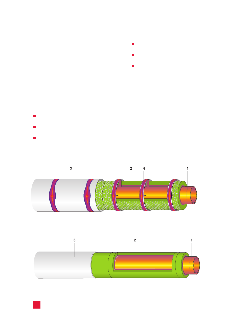
Insulation system with a spacer ring
The lack of spacers gives rise to lower heat
losses.
It yields an even surface temperature across
the sheet cladding.
In comparison to wired mats, a more shallow
insulation thickness can be applied. Theoperating
costs of the installation decrease as a result of
lower heat loss.
Generally speaking, a spacer or support structure
functions as a thermal bridge, as a result of which
theheat loss in the total insulation is increased
considerably.
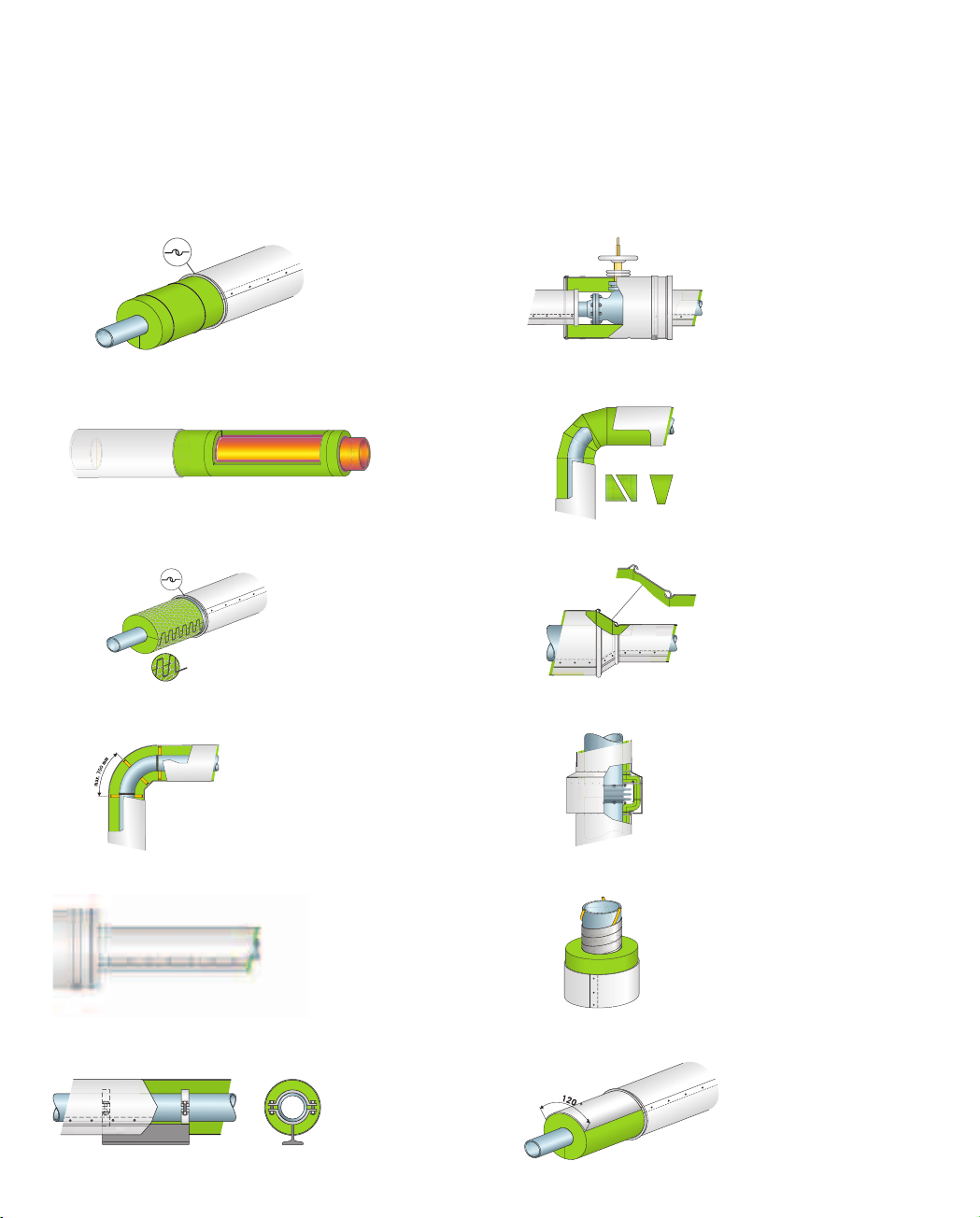
1. Pipe - 2. Insulation: ProRox® Wired Mats - 3. Cladding - 4.Spacer ring
Insulation system without a spacer ring
1. Pipe - 2. Insulation: ProRox® Pipe Sections or Pipe Wraps (Mats): ENERWRAP® MA 960NA - 3. Cladding
26
Page 30
Required insulation thicknesses
If the three insulation systems are compared,
taking into consideration similar heat losses,
clear advantages are seen with regard to the
insulation thicknesses with systems using pipe
sections or pipe wraps (mats). These do not use
spacers, in contrast to insulation systems made
using wired mats. The table below shows the
required insulation thicknesses taking into
account the following boundary conditions:
Medium temperature: 480 °F (250 °C)
Ambient temperature: 50 °F (10 °C)
Wind speed: 1.1 mph (5 m/s)
Cladding: Aluminum
Heat loss: 150 BTU/ft.hr (150 W/m)
Application of spacers in the case of wired mats
of piping
Insulation
Minimum Insulation Thickness
NA
ENERWRAP® MA 960
NA
Wired mats
NPS
(inch)
Pipe Diameter
Nominal diameter
Ø DN
Pipe diameter
(mm)
Pipe sections Pipe wraps (mats)
®
PS 960
ProRox
inch inch inch
2 50 60 1" n.a. n.a.
3 80 89 1" n.a. n.a.
4 100 108 1.5" n.a. n.a.
6 150 159 2" n.a. n.a.
8 200 219 2.5" n.a. 5"
10 250 273 3" n.a. 6"
12 300 324 4" 4" 7.5"
14 350 356 4.5" 4.5" 8"
Multiple layer insulation n.a. = not applicable
27
Page 31

1.2 Insulation of piping
Selection of pipe insulation systems
Generally, the best insulation is achieved using
ProRox® Pipe Sections. The preformed sections
are quick and easy to install. Their excellent fit
and high compression resistance means pipe
sections can be applied in a single layer without
any additional spacers. They also have a lower
insulation thickness. Pipe wraps (mats), are
usually applied for the insulation of large pipe
diameters and can be applied to shaped pieces
like elbows and T-joints.
Comparison
®
ProRox
pipe sections and pipe wraps (mats)
offer theadvantage that spacers are generally
not required.
®
ProRox
pipe sections and pipe wraps
(mats) are applied more quickly without the
inter ference of spacers.
Both products offer an even, firm surface
for installing the cladding.
The lack of spacers creates lower heat loss.
It yields an even surface temperature
across the cladding.
In comparison to wired mats, a more
shallow insulation thickness can be used.
With a same insulation thickness, the
operational costs of the installation
decrease as a result of lower heat losses.
Generally speaking, a spacer or support structure
functions as a thermal bridge, as a result of which
the heat loss in the total insulation is increased
considerably.
The design of an insulation system depends upon
many factors such as the dimensions, mechanical
loads, safety aspects, economics, etc.
Consequently this also requires a considered
selection of the insulation material.
28
Page 32

1.2.1 Insulation with pipe sections
Generally, the best insulation is achieved using
ProRox® Pipe Sections. The sections can be used
up to temperatures of 1400 °F (760 °C) when
using ProRox® PS 980NA Type V insulation. They
are supplied ready split and hinged for quick
and easy snap-on assembly and are suitable for
thermal and acoustic insulation of industrial pipe
work. Their excellent fit and high compression
resistance means pipe sections can be applied
in a single layer without any additional spacers
or support structures. Consequently the number
of thermal bridges, which have a negative
influence on the insulation, is greatly reduced,
while a low thickness may be applied compared
to wired mats. The result is considerably reduced
installation time and costs. The lack of spacers
and “unforeseen” gaps minimizes heat loss and
the risk of personnel injuries due to hot spots on
the cladding.
At temperatures above 550 °F (300 °C), the
provisional application of spacers must be
determined in each individual case. ProRox®
Pipe Sections are available in a wide range of
diameters, ranging from NPS 1/2" (23 mm) to
36" (914 mm)
NOTE
D
ue to their low thermal conductivity, better
thermal insulation values can be achieved
with pipe sections than with wired mats.
With insulation on straight pipe sections, a
combination of both products in the same
insulation thickness is therefore not advisable.
If this combination is essential, for example,
in the case of bends or shaped pieces, it is
vital to select the correct insulation thickness.
This is the only way to guarantee that no
unexpected, potentially hazardous surface
temperatures occur.
Insulation thicknesses to guarantee
protection against contact
The table below is an initial guide to help select
suitable insulation thicknesses for the guards.
Itisbased on the following boundary conditions:
Ambient temperature: 75 °F (25 °C)
Wind speed: 1.1 mph (0.5 m/s)
Cladding: Aluminum
Maximum surface temperature: 140 °F (60 °C)
Insulation: ProRox® PS 960
NA
pipe sections
of piping
Insulation
Pipe Diameter Temperature
Nominal
NPS
(inch)
he thicknesses mentioned above should be seen as an indication. In the event of differing boundary conditions, please
T
contact the ROXUL
or NAIMA 3E Plus
diameter
Ø DN
1 25 33 0.5" 0.5" 0.5" 0.5" 1" 1" 1" 1"
2 50 60 0.5" 0.5" 0.5" 1" 1" 1" 1.5" 1.5"
3 80 89 0.5" 0.5" 1" 1" 1" 1.5" 1.5" 2"
4 100 114 0.5" 0.5" 1" 1" 1" 1.5" 1.5" 2"
6 150 168 0.5" 1" 1" 1" 1.5" 1.5" 2" 2"
8 200 219 0.5" 1" 1" 1.5" 1.5" 1.5" 2" 2.5"
10 250 273 0.5" 1" 1" 1.5" 1.5" 2" 2" 2.5"
12 300 324 0.5" 1" 1" 1.5" 1.5" 2" 2" 2.5"
Pipe
diameter
(mm)
®
Technical Services Team. The thermo-technical engineering program "ROCKASSIST" (coming soon)
®
can be used to design the insulation according to the specific requirements.
<250 °F
(<120 °C)
inch inch inch inch inch inch inch inch
300 °F
(150 °C)
350 °F
(175 °C)
400 °F
(200 °C)
450 °F
(230 °C)
500 °F
(260 °C)
550 °F
(290 °C)
(315 °C)
600 °F
29
Page 33

1.2 Insulation of piping
Installation
Before starting the insulation works, ensure
that all preparatory work on the object has been
completed. Refer to Chapter 1.1 for details.
The ProRox® PS 900 Series pipe sections are
mounted directly onto the pipe to form a close
fit. With horizontal pipes, the lengthwise joint of
the pipe section should be turned towards the
underside at the 6 o’clock position. With vertical
pipes, the lengthwise joints should be staggered
at an angle of 30 ° to one another. Secure the pipe
sections with galvanized binding wire or with steel
bands. With an insulation thickness exceeding
5 inches (120 mm) [or temperatures > 550 °F
(300 °C)], install the insulation in at least two
layers. If the insulation is assembled in multiple
layers, the joints of the individual insulation layers
must be staggered.
Support structures and spacers
Spacers are not generally essential in insulation
systems with pipe sections. With pipes that are
exposed to large mechanical loads (e.g. strong
vibrations) and/or temperatures above
550 °F (300 °C), determine whether a spacer ring
is required in each individual case.
With pipes that have been installed vertically,
with a height in excess of 13 feet (4 m), fit support
structures to transfer the dead load of the
insulation system onto the pipe. Attach the first
support ring to the lowest point of the vertical
pipe. The distance between the support rings
should not exceed approximately 13 feet (4 m).
1. Pipe - 2. Insulation: ProRox® Pipe Sections -
3. Clamp or binding wire - 4. Sheet cladding -
5. Sheet-metal screw or rivet
30
Page 34

1.2.2 Insulation with pipe wraps (mats)
Pipe wraps (mats), such as ENERWRAP® MA 960NA
are the latest development in the insulation
business. ENERWRAP® MA 960NA is a stone wool
insulation wrap available with black mat or
reinforced foil facing. The flexible application
makes the product easy to cut and install. Pipe
wraps (mats) are ideal for installations involving
large diameter pipes and a high number of shaped
pieces such as elbows or T-joints.
ENERWRAP® MA 960NA can be applied up to
temperatures of 1200 °F (650 °C). Due to the high
compression resistance, pipe wraps (mats) can be
applied without additional spacers in many cases.
Consequently, the number of thermal bridges
which have a negative influence on the insulation,
is greatly reduced.
Pipe Diameter Temperature
NPS
(inch)
Nominal
diameter
Ø DN
Pipe
diameter
(mm)
<250 °F
(<120 °C)
inch inch inch inch inch
The result is considerably reduced installation
time and costs. The lack of spacers minimizes
heat loss and the risk of personal injuries caused
by hot spots on the cladding. Pipe wraps (mats)
are precisely tailored to the corresponding length
of the pipe circumference on site and are fastened
with clamps.
Insulation thicknesses to guarantee
protection against contact
The table below is an initial guide to help select
suitable insulation thicknesses for the guards. It is
based on the following boundary conditions:
Ambient Temperature 75 °F (25 °C)
Wind speed: 1.1 mph (0.5 m/s)
Cladding: Aluminum
Maximum surface temperature: 140 °F (60 °C)
Insulation: ProRox® PS 960
300 °F
(150 °C)
400 °F
(200 °C)
NA
500 °F
(260 °C)
600 °F
(315 °C)
of piping
Insulation
12 300 324 0.5" 1" 1.5" 2" 2.5"
16 400 406 1" 1" 1.5" 2" 3"
20 500 508 1" 1" 1.5" 2.5" 3"
The thicknesses mentioned above should be seen as an indication.
In the event of differing boundary conditions, please contact the ROXUL
engineering program "ROCKASSIST" (coming soon) or NAIMA 3E Plus
the specific requirements.
®
Technical Services Team. The thermo technical
®
can be used to design the insulation according to
31
Page 35

1.2 Insulation of piping
Installation
Before starting the insulation works, ensure that
all preparatory work on the object has been
completed. Refer to Chapter 1.1 for details.
Cut the wraps (mats) to the required length, based
on the external insulation diameter (pipe diameter
+ two times the insulation thickness). Fasten the
wrap (mat) firmly to the pipe with steel bands.
Ensure that the wraps (mats) form a tight joint
and that no lengthwise joints or circular joints are
visible. The joints of the individual wraps (mats)
are securely taped with self-adhesive aluminum
tape. If the insulation is assembled in multiple
layers, the joints of the individual insulation layers
must be staggered.
Support structures and spacers
Spacers are not generally essential in insulation
systems with load bearing wraps (mats). With
pipes that are exposed to large mechanical loads
(e.g. strong vibrations), determine whether a
spacer ring is required in each individual case.
With pipes that have been installed vertically, with
a height in excess of 14 feet (4 m), fit support
structures to transfer the dead load of the
insulation system onto the pipe. Attach the first
support ring to the lowest point of the vertical
pipe. The distance between the support rings
should not exceed approximately 14 feet (4 m).
1. Pipe - 2. Insulation: ENERWRAP® MA 960NA - 3. Self-adhesive aluminum tape - 4. Steel bands - 5. Sheet cladding -
6.Sheet-metal screw or rivet
32
Page 36

1.2.3 Insulation with wired mats
Pipe insulation with wired mats has been a
time-tested universal solution for many decades
now. Due to their flexibility and high temperature
resistance, wired mats can be easily cut and
mounted onto the piping. These wired mats are
ideal for application on large pipe diameters and
shaped pieces as elbows or T-joints.
Wired mats have a relatively low resistance to
pressure and from a practical point of view should
only be mounted in combination with spacers.
Because of theresulting thermal bridges, better
insulation performances are often achieved in the
lower and middle temperature range [up to 550 °F
(300 °C)] with pipe sections or load bearing wraps
(mats) rather than with wiredmats.
Installation
Before starting the insulation works, ensure that
all preparatory work on the object has been
completed. Refer to Chapter 1.1 for details.
With an insulation thickness of more than 5 inches
(120 mm) [or temperatures > 550 °F (300 °C)],
apply multiple layer insulation. If the insulation is
assembled in multiple layers, the lengthwise and
crosswise joints of the individual insulation layers
must be staggered. If mechanical loads are
anticipated, use steel straps to secure the wired
mats.
of piping
Insulation
Cut the wrap (mat) to a length so that it can be
fitted to the pipe with slight pre stressing. Wire
the closing joints (lengthwise and circular) of the
wraps (mats) together using steel wire or secure
with wrap (mat) hooks. Stainless steel pipes and
pipes with an operating temperature > 750 °F
(400 °C) can only be insulated with wired mats
with stainless steel stitching wire and wire netting
to prevent galvanic corrosion cracking.
1. Pipe - 2. Insulation: ProRox® Wired Mats - 3. Stitching
of the joint edge with binding wire - 4. Sheet cladding -
5. Sheet-metal screw or riveted bolt - 6. Spacer ring
1. Pipe - 2. Insulation: ProRox® Wired Mat- 3. Joint
edge closed with mat hooks - 4. Sheet-metal cladding -
5.Sheet-metal screw or riveted bolt - 6. Spacer ring
Support structures and spacers
As wired mats do not offer sufficient resistance
topressure to bear the weight of the cladding,
spacer or support structures should be applied.
More information can be found in 1.2.4.
With pipes that have been installed vertically,
witha height in excess of 14 feet (4 m), fit support
structures to transfer the dead load of the
insulation system onto the pipe. Attach the first
support ring to the lowest point of the vertical
pipe. The distance between the support rings
should not exceed approximately 14 feet (4 m).
33
Page 37

1.2 Insulation of piping
m
a
x
.
2
7
"
(
7
0
0
m
m
)
1.2.4 Insulation support
A. Spacers
The purpose of spacers is to keep the cladding at
a predetermined distance from the pipe. Spacers
are essential when the insulation (e.g. wired mats)
cannot bear the mechanical load of the cladding.
The use of spacers is generally not necessary
ifpipe sections or pipe wraps (mats) are used.
Consideration should be given to support
structure or spacers on pipes where mechanical
loading (e.g. strong vibrations) of the insulation is
expected and/or the temperature is higher than
550 °F (300 °C).
Spacer rings usually consist of metal rings on
which the sheet cladding rests, and metal or
ceramic bars used as spacers, which rest on the
pipe. Elastic spacers such as Omega clamps are
frequently used to reduce the transference of
vibrations. With steel spacers, apply at least three
bars, whereby the maximum distance – measured
as circumference of the external ring – must be a
total of maximum 16 inch (400 mm). With ceramic
spacers, apply at least four bars at a maximum
permissible distance of 16 inch (400 mm).
Dimension spacers of support construction
The number of spacers depends on the insulation,
temperature and the mechanical load. Use the
following intermediate distances as a guide.
Horizontal
Insulation
system
Pipe sections none 10 to 13 ft none 16 to 20 ft
Load bearing wraps (mats) none 10 to 13 ft none 16 to 20 ft
Wired mats 3.3 ft 3.3 ft 3.3 ft 16 to 20 ft
piping
≤ 550 °F > 550 °F ≤ 550 °F > 550 °F
Vertical
piping
)
m
m
0
0
4
(
"
6
1
.
x
a
m
1. Pipe - 2. ProRox® insulation - 3. Spacer - 4. Thermal
dividing layer - 5. Cladding
The spacers on pipes are located under the
circular joint of the cladding. On shaped sections
such as pipe elbows, spacers are fitted at the start
1. Pipe - 2. ProRox® insulation - 3. Spacer - 4. Thermal
dividing layer - 5. Support ring
34
and at the end. If the external distance between
the two spacers exceeds 27 inch (700 mm), place
additional spacers between the two.
Page 38

B. Support construction
The purpose of support structures is to transfer
the mechanical load of the insulation system and
the forces affecting the insulation system onto the
object. Support structures are essential in the
case of vertical piping. In addition to the static and
dynamic forces, changes in piping length and
support structures due to temperature must also
be taken into account when dimensioning. Support
structures are fastened to mounting supports,
which are welded to the pipe beforehand, or are
mounted directly onto the pipe via a clamping
action with so-called double clamping rings. With
temperatures above 650 °F (350 °C), the support
structures must be made of high-temperature steels.
The table below is an initial dimensioning guide,
and shows the weight of the insulation system
against the nominal width of the pipe and the
insulation thickness. The table accounts for an
insulation with an apparent density of 6 lb/ft3
(100 kg/m³), including the spacer and a 0.20 inch
(1.0 mm) strong galvanized sheet.
Weight of the insulation (lb/ft pipe)
1. Support ring - 2. Bar - 3. Rivet or screw connection -
4. Thermal decoupling - 5. Clamping screw - 6. Screw
nut - 7. Internal clamping ring
of piping
Insulation
Pipe Diameter
Nominal
NPS
diameter
(inch)
0.5 15 21 lb / ft 0.3 0.5 0.8 1.1 1.5 2.5 3.7 5.2
1.0 25 34 lb / ft 0.5 0.7 1.0 1.4 1.8 2.8 4.1 5.7
2.0 50 60 lb / ft 0.8 1.1 1.5 1.9 2.4 3.6 5.0 6.7
2.5 65 76 lb / ft 1.0 1.3 1.7 2.2 2.7 4.0 5.5 7.2
3.0 80 89 lb / ft 1.2 1.5 2.0 2.5 3.0 4.3 5.9 7.7
4.0 100 114 lb / ft 1.5 2.0 2.5 3.0 3.6 5.1 6.8 8.7
8.0 200 219 lb / ft 2.9 3.6 4.4 5.2 6.1 8.1 10.3 12.8
12.0 300 324 lb / ft 4.4 5.3 6.3 7.4 8.5 11.0 13.8 16.8
20.0 500 508 lb / ft 7.2 8.6 10.2 11.8 13.5 17.0 20.8 24.8
28.0 700 711 lb / ft 10.0 12.0 14.0 16.2 18.4 22.9 27.8 32.9
planar surface lb / ft
Ø DN
Pipe
diameter
(mm)
Units of weight of
insulation system
2
1.00 1.50 2.00 2.50 3.00 4.00 5.00 6.00
1.3 1.6 1.8 2.1 2.3 2.8 3.3 3.8
Insulation Thickness (inch)
35
Page 39

1.2 Insulation of piping
1.2.5 Cladding
Suitable cladding should be applied to protect the
insulation from weather influences, mechanical loads
and (potentially corrosive) pollution. Selecting the
appropriate cladding depends on various factors, such
as working loads, foot traffic, wind and snow
accumulations, ambient temperatures and conditions.
NOTE
An insulation system resistant to foot traffic
must not become permanently damaged if a
person weighing 220 lbs (100 kg), (weight
including any tools being carried) walks
across it. It is not designed to bear additional
loads, such as the placing of heavy equipment.
For the purpose of the safety regulations, a
durable insulation is not considered to be a
walkable surface.
When selecting the appropriate cladding, take the
following points into account:
As a general rule, galvanized steel is used in
buildings due to its mechanical strength, fire
resistance and low surface temperature (in
comparison to an aluminum cladding).
Aluminum is used outdoors, because it is easy
to fit and more cost-effective than stainless
steel and does not tend to corrode under
common weather conditions.
In corrosive environments, aluminized steel,
stainless steel or glass reinforced polyester is
used as cladding. Stainless steel is
recommended for use in environments with a
fire risk.
The surface temperature of the cladding is
influenced by the material type. The following
applies as a general rule: the shinier the
surface, the higher the surface temperature.
To exclude the risk of galvanic corrosion, only
use combinations of metals that do not tend to
corrode due to their electrochemical potentials
(also see page 21 in Chapter 1.1).
For acoustic insulation, a noise absorbent
material (bitumen, mylar foil) is mounted on the
insulation or inside the cladding. To reduce the
risk of fire, limit the surface temperatures of
the cladding to the maximum operating
temperature of the noise absorbent material.
Max. surface temperature
Cladding material Areas at risk
Aluminum sheet - -
Aluminum/zinc coated steel sheet - -
Galvanized steel sheet -
Austenitic stainless steel sheet
Aluminized steel sheet
Plastic-coated steel or aluminum - -
Glass fiber-reinforced polyester
®
Rocktight)
(e.g. ProRox
Coatings/mastics - - 175 °F (80 °C)
Foils - -
The thickness of the metal sheet depends on the pipe dameter and the type of the metal.
With special acoustic requirements, a larger thickness [> 0.04" (1 mm)] is generally used.
36
of fire
-
Corrosive
environment
< 120 °F
(50 °C)
< 140 °F
(60 °C)
< 190 °F (90 °C)
> 140 °F
(60 °C)
Page 40

Recommended sheet thickness and overlaps regarding cladding made from flat sheets (CINI)
Surface (cladding) temperature °F
Aluminum
cladding
100
105
110
115
120
125
130
Galvanized
steel
Stainless
steel
Paint-coated
Plastic
cladding
Minimum thickness (inches) of metal cladding sheet (recomended by CINI)
External diameter of
the insulation (in)
< 5.5" 0.024 0.022 0.020 0.020 0.020
5" to 12" 0.031 0.031 0.031 0.031 0.031
> 12" 0.039 0.031 0.031 0.031 0.031
Aluminum
(CINI 3.1.01)
Aluminized
steelsheet
(CINI 3.1.02)
Alu-Zinc coated
steel sheet
(CINI 3.1.03)
Zinc coated
steelsheet
(CINI 3.1.04)
Austenitic stainless
steel sheet
(CINI 3.1.05)
of piping
Insulation
The recommended sheet thickness deviates to a
certain level per standard/country. The thickness
recommended by CINI is shown in the table above
(values converted to inches). See page 148 in
Chapter 3.2.2 for the thickness according to DIN
4140 and BS 5970.
To reduce the risk of galvanic corrosion, it is
important to use the correct screws, straps etc.
See the table on page 21 for more information.
The basic guidelines are:
Fasten sheet cladding on lengthwise joints with
at least six sheet metal screws or blind rivets
every meter.
Place the screws or blind rivets equidistant.
Ifscrews or rivets are fitted in two rows, do not
stagger the screws or rivets.
The cladding can also be held in place with
corrosion-resistant straps instead of screws
orrivets.
Do not use aluminum screws.
Influence of the cladding on the
surface temperature
In addition to the insulation thickness, the thermal
conductivity of the insulation and the ambient
conditions (for example temperature and wind),
the surface temperature of insulation is also
influenced by the emission ratio (emissivity) of the
cladding.
The following applies as a general rule for
thermal insulation: the shinier a surface is (lower
emissivity), the higher the surface temperature.
The following example shows the various surface
temperatures that depend on the cladding:
Diameter: 4 1/2" (114 mm)
Temperature of the medium: 930 °F (500 °C)
Place of installation: Interior [Wind speed 1.1
mph (0.5 m/s)]
Insulation: ENERWRAP® MA 960NA
pipe wrap (mat), thickness 4" (100 mm)
Various cladding materials
- Aluminum sheet
- Galvanized steel sheet, bright
- Stainless steel
- Paint-coated plastic cladding
37
Page 41

1.2 Insulation of piping
1.2.5 Cladding
Cladding in corrosive environments
To guarantee the functionality of industrial/
mechanical insulation (sometimes referred to as
technical insulation), it is important to protect it
against atmospheric influences and prevent the
ingress of moisture into the insulation. Moisture in
the insulation system increases thermal conductivity,
thereby reducing the effectiveness of the thermal
protection. It also poses a high risk of corrosion to
the component. In certain applications, the cladding
system is also expected to offer chemical resistance,
as well as being resistant to cleaning methods such
as steam blasting. Alongside the insulation and
construction, selecting a suitable cladding system is
very important as it forms the basis for a long service
life, low maintenance costs and low heat loss of a
industrial/mechanical insulation. ROXUL® offers
ProRox® Rocktight, an innovative fiberglass polyester
cladding system.
Thepolyester then hardens when exposed to
ultraviolet (UV) light. Once hardened, ProRox®
Rocktight is watertight and forms a mechanical
protection for the insulation.
The advantages:
Long service life:
ProRox® Rocktight creates a sealed, watertight
cladding for ROXUL insulation systems. This
minimizes damage caused by atmospheric
influences or general wear and tear. ProRox®
Rocktight is resistant to many chemical
substances and forms a mechanical protection for
the insulation.
Easy to clean:
Insulation systems cased in ProRox® Rocktight can
be cleaned with steam-jet air ejectors, without the
risk of water penetrating the insulation and
causing damage.
Low start-up costs:
The cutting and processing take place directly on
site. This avoids costs associated with
prefabrication of steel cladding.
Flexible applications:
ProRox® Rocktight can be used for cold and
thermal insulation of underground and
aboveground pipes, for example in offshore plants.
Its high flexibility enables application on complex,
shaped objects.
ProRox® Rocktight – a durable protection
for insulation
ProRox® Rocktight is a fiberglass reinforced
polyester wrap, which hardens when exposed to
ultraviolet (UV) light. The material contains resins,
glass fibers and a special filling agent and is
(unprocessed) protected against UV rays by foils on
both sides.
ProRox® Rocktight is soft and flexible when
unprocessed. Itcan be cut or trimmed in any shape
and easily mounted onto the insulation in this state.
38
ProRox® Rocktight is characterized by easy
processing. It can be cut easily using a knife directly
on site and, as an unhardened ProRox® Rocktight
wrap (mat) is highly flexible, it can be simply shaped
to cover complex geometric shapes such as pipe
elbows, T-joints or pipe fittings. ProRox® Rocktight
has a protective foil on both sides. It is supplied in
rolls in cardboard packaging. The roll is also
wrapped in black foil that is resistant to UV light. The
underside (the side facing the object) is covered with
a dark foil and has a rough, self-adhesive surface.
The flat surface of the outside is covered with a white
foil. After each use, place the roll in the sealed
cardboard packaging to minimize the risk of
hardening caused by daylight or UV light.
Page 42

ProRox® Rocktight requires a dry, clean (ventilated)
work environment. For outdoor applications, tents
should be erected if necessary, to protect the
unhardened ProRox® Rocktight wrap (mat) from UV
light.
NOTE
High temperatures: ProRox® Rocktight can
be used in temperatures of up to 190 °F
(90 °C).
Chemical resistance: ProRox® Rocktight is
resistant to numerous chemicals.
Expansion joints: fit expansion joints to
accommodate expansion of the ProRox®
Rocktight material and the steel pipe.
1.2.6 Pipe hangers and pipe supports
There is a wide range of solutions for pipe
hangers and pipe supports. The following
illustrations show the possibilities described
below for insulation systems:
Pipe hangers in direct contact with the piping
Pipe supports in direct contact with the piping
Pipe supports not in direct contact with the
piping (commonly used with cold insulation
systems)
Pipe support in direct contact with the piping
1. Pipe - 2. Insulation: ProRox® PS 960NA – pipe section
- 3.Sheet cladding - 4. Pipe clamp - 5. Pipe saddle
Pipe support not in direct contact with the piping
1. Pipe - 2. Insulation: ProRox® PS 960NA pipe sections-
3.Sheet cladding - 4. Load-bearing insulation -
5.Seal - 6.Stirrup - 7. Pipe saddle
of piping
Insulation
Pipe hangers in direct contact with the piping
1. Pipe - 2. Insulation: ProRox® Pipe Sections -
3.Collar - 4. Sheet cladding - 5. Pipe hanger
A basic rule applying to all pipe attachments is
that the insulation system (e.g. the insulation and
cladding) must not be damaged if the piping
expands. Damage to the cladding of outdoor
installations, in particular, can allow the ingress
ofmoisture in the material. The result may be
permanent damage of the insulation system
andas a consequence high heat losses,
dangerously high surface temperatures and
corrosion etc.
39
Page 43

1.2 Insulation of piping
2"
(50 mm)
5
0.8"
(20 mm)
1.2.7 Insulation of valves and flanges
Heat loss incurred through non insulated fixtures
such as valves and flanges are substantial, even at
low temperatures. An uninsulated valve located
outside loses as much heat at 250 °F (120 °C) as
100 ft (30.5 m) of uninsulated piping. The
temperature of the medium can also decrease to
such an extent at non-insulated fittings or flanges,
that process critical temperatures are reached, at
which point for example, the medium will start to
crystallize. Valves and flanges should therefore be
insulated as much as possible. To avoid damage
during inspection or repairs, the insulation for
valves and flanges is designed with removable
coverings or hoods, to allow rapid disassembly.
Removable coverings or hoods are usually
insulated from the inside with wired mats or
flexible ProRox® insulation (FSL Series). The
coverings are fastened to the object with lever
fastenings, which are fixed directly onto the
covering or on to straps. Take the following
conditions into account when designing insulated
coverings for fittings and flanges:
The overlap distance of the insulated covering
over the insulated pipe should be at least 2"
(50 mm).
The pipe insulation should end at the flanges,
leaving a gap equal to the bolt length +1.2"
(30 mm) and should be closed off with a lock
washer so the flange can be loosened without
damaging the insulation.
With valves, an extended spindle should
preferably be fitted horizontally or below the
pipe to prevent leakage along the spindle shaft.
The cladding must be fitted to prevent the
ingress of moisture in the insulation. On
inclined or vertical piping, for example, mount
rain deflectors above the removable coverings.
If the ingress of moisture into the insulation is
unavoidable, make 0.4" (10 mm). diameter drain
holes in the removable covering.
1. Pipe - 2. ProRox® insulation-
3. Cladding- 4. Sheet-metal screw or Rivet -
5.Swage- 6.Drainage opening -
7. Strap - B ≥ 2" (50 mm) - A= bolt length +1.2" (30 mm)
A number of possible design options for insulation
systems for pipe fittings and flanges follow:
®
1. Pipe - 2. ProRox
metal screw or rivet - 5. Rain deflector - 6. Lock washer
- 7. Straps - 8. Rain deflector B ≥ 2" (50 mm) - A = bolt length + 1.2" (30 mm)
insulation - 3. Cladding- 4. Sheet-
40
Page 44

2"
(50 mm)
0.8"
(20 mm)
1. Pipe - 2. ProRox® insulation - 3. Cladding- 4. Sheetmetal screw or rivet - 5. Swage - 6.Drainage opening
- 7. Straps – B ≥ 2" (50 mm)
1. Pipe - 2. ProRox® insulation - 3.Cladding - 4. Sheetmetal screw or rivet - 5. Swage- 6.Drainage opening
- 7. Straps – B ≥ 2" (50 mm) - A = Bolt length + 1.2"
(30 mm)
1. Pipe - 2. ProRox® insulation - 3.Sheet -
4. Sheet-metal screw or rivet - 5. Rain deflector -
6. Lock washer - 7. Straps - 8. Lock washer -
B ≥ 2" (50 mm) - A = Screw length +1.2" (30 mm)
Leakages
With pipes where a leaking fluid content could
damage the insulation or the coating system in
the removable covering, mount flange straps with
a leak detection fitting around the flange. Flange
bands can also prevent flammable products from
penetrating into the insulation material and can
help prevent the outbreak of fire.
of piping
Insulation
1. Pipe - 2. Insulation: ProRox
3. Cladding - 4. Sheet-metal screw or rivet -
5. Removable coverings (insulated from the inside) -
6. Swage
®
Pipe Sections -
®
1. Pipe - 2. ProRox
metal screw or rivet - 5. Swage - 6.Flange band - 7.
Leak detection fitting - 8. Clamps
insulation - 3. Cladding- 4. Sheet-
41
Page 45

1.2 Insulation of piping
1.2.7 Insulation of valves and flanges
1. Pipe - 2. ProRox® insulation - 3. Cladding - 4. Sheetmetal screw or rivet - 5. Collar - 6. Collar -
7. Clamps - 8.Rain deflector - 9. Leak detection fitting B ≥ 2" (50 mm) - A = bolt length + 1.2" (30 mm)
pipe elbow with clamps or binding wire. Joints
between the individual segments are plugged
tightly with loose ROXUL insulation.
1. Pipe - 2. Insulation: ProRox® Pipe Sections -
3.Cladding - A and B = Segmented pipe sections
1.2.8 Insulation of pipe elbows and
Tpieces
The cladding of elbows and T-pieces is susceptible
to damage, due to expanding or vibrating pipes.
There is a particular risk of moisture penetrating
damaged swage connections in the cladding, if the
object is located outdoors.
For the insulation of shaped pieces, we
recommend using the same insulation in the
same thickness as used for the pipe.
Insulation of pipe elbows with ROXUL®
pipe sections
For the insulation of pipe elbows with pipe
sections (e.g. ProRox® PS 960NA), the pipe sections
are cut into segments and tightly fitted onto the
pipe elbow with the lengthwise joints facing
downwards. The angular division of the segments
should correspond to the radius of the pipe elbow.
The pipe section segments are fastened to the
42
Insulation of pipe elbows with wired
mats or ProRox® pipe wraps (mats)
If the piping is insulated with wired mats or pipe
wraps (mats), shaped pieces such as pipe elbows
or T-pieces are generally insulated with the same
wraps (mats). In this case, the wraps (mats) are
cut into so-called fish-shaped elbow segments.
These are mounted onto the pipe elbow to seal the
elbow. With wired wraps (mats), all the joints (both
circular and lengthwise joints) are sewn together
with binding wire or wrap (mat) hooks. Spacers
are required at least at the start and end of the
elbow (for more details, please see page 34).
Pipe wraps (mats) are fixed to the pipe elbow with
metal or plastic straps. Any gaps between the
individual segments should be plugged with
insulation. Secure the joint edges with selfadhesive aluminum tape.
Page 46

The diagrams below show how the sheet is
0.6" (15 mm)
0.4" (10 mm)
mounted onto shaped pieces.
1. Pipe - 2. ProRox® insulation - 3. Cladding - A to C:
Elbow segments of wraps (mats)
1.2.9 Reducers
Pipes that branch out with many outlets reduce
the pipe diameter. Examples of how to install
reducers follow:
1. Pipe - 2. ProRox® insulation - 3. Cladding - 4. Sheetmetal screw or rivet- 5.Swage - 6. Reducer
of piping
Insulation
®
1. Pipe - 2. ProRox
insulation - 3. Cladding
1. Pipe - 2. ProRox® insulation - 3. Cladding -
4. Drainage opening - 5.Edging with mastic compound
®
1. Pipe - 2. ProRox
metal screw or rivet- 5.Swage - 6. Reducer
insulation - 3. Cladding - 4. Sheet-
43
Page 47

1.2 Insulation of piping
4"
(100 mm)
4" (100 mm)
1.2.10 Expansion joints
In thermal insulation systems, large differences
between the piping and the cladding temperature
can occur. The materials used for the pipe,
insulation, insulation support and cladding also
have different thermal expansion coefficients.
Thisleads to different thermal elongations of the
various components in the insulation system,
which must be allowed for using constructive
measures. The elongation “Δl” can be determined
as follows:
Δl = l ⋅ Δt ⋅ a
In this formula, l corresponds to the length of the
pipe, Δt corresponds to the difference in
temperature between the cold and warm pipe (or
cladding) and a corresponds to the linear thermal
expansion coefficient (see tables in Chapter 3).
Example for the thermal elongation of steel
Δl (inch per foot) Δt (°F) Δt (°C)
0.004 50 28
0.008 100 56
0.012 150 83
0.016 200 111
If bellow expansion joints for thermal length
compensation have been built into the pipe, the
insulation system will also bellow along with the
pipe movements, potentially compromising the
insulation. The expansion bellows are covered
with a sheet that is then insulated (see diagrams
on the right). With temperatures above 550 °F
(300 °C), do not use galvanized sheets due to the
risk of galvanic corrosion (cracking).
1. Pipe - 2. ProRox® insulation - 3. Cladding-
4. Aluminum foil - 5. Cover sheet - 6. Wrap (mat) pin with
clip - 7. Spacer
To compensate for thermal expansion of the
cladding, install the expansion joints shown below.
®
1. Pipe - 2. ProRox
4. Sheet-metal screw or rivet - 5. Swage -
6.Metal strap - 7. Circumferential seam
insulation - 3. Cladding -
44
Page 48

1.2.11 Tracing
When media are transported over long distances,
in particular, the media inside the piping can spoil,
set or be at risk from frost in the winter. Insulation
can reduce heat losses and postpone the moment
at which the installation freezes. Insulation alone,
however, cannot indefinitely prevent the
installation from freezing. Installing additional
tracing may be necessary between the object and
the insulation.
of piping
Insulation
A distinction is made between pipe tracing and
electrical tracing. In pipe tracing systems, a
heating pipe is fitted parallel and close to the
media pipe. Steam, warm water or thermal oil
flows through the tracing pipes as a heat transfer
medium. Electrical tracing consists of cables
mounted onto the pipes. These cables heat the
pipes
Traced pipes can be insulated with pipe sections
or wraps (mats). Ensure that no insulation
occupies the space between the tracing and the
pipe; otherwise the heat transfer will be
hampered. Pipes are therefore often wrapped in
aluminum foil. If pipe sections are used, select a
correspondingly larger internal diameter of the
pipe section. With vertical piping, sealing the end
of each pipe section with loose ROXUL® insulation
is recommended to prevent convection (chimney
effect).
The diagrams on the right show various design
options.
1. Pipe - 2. Insulation: ProRox® Pipe Sections -
3.Electrical tracing - 4. Aluminum foil - 5. Cladding
®
1. Pipe - 2. Insulation: ENERWRAP
- 3. Tracing - 4.
Mats
5.Cladding
Aluminum
MA 960NA or Wired
foil -
1. Pipe - 2. Insulation: ProRox® Pipe Sections -
3. Tracing- 4. Binding tape - 5. Cladding
45
Page 49

1.2 Insulation of piping
1.2.12 Foot traffic
Avoid walking on insulated pipes, as this can
damage the insulation. Damage caused by foot
traffic includes dented sheet cladding and gaps at
the sheet seams. Water can penetrate the
insulation through these gaps and cause lasting
damage to the entire insulation system. The result
is often greater heat losses and corrosion.
NOTE
An insulation system resistant to foot traffic
must not become permanently damaged if a
person weighing 220 lbs (100 kg), (weight
including any tools being carried) walks on it.
It is not designed to bear additional loads,
such as the placing of heavy equipment. For
the purpose of the safety regulations, a
durable insulation is not considered to be a
walkable surface.
In special applications, reinforcing the cladding is
recommended, e.g. using a reinforcement sheet.
1. Pipe - 2. Insulation:
Sections - 3. Reinforcement sheet (may not be
required) - 4. Cladding - 5. Sheet-metal screw or rivet -
6. Joggle
ProRox® PS 980
NA
Pipe
Pipe insulation systems resistant to foot traffic
require an insulation material with a high
mechanical strength (e.g. ProRox® PS 980NA pipe
sections). Using other insulation materials such
as wired mats, which are not resistant to
pressure, is not recommended, as the sheet
cladding only rests on the spacers and tends
todent when walked upon.
46
Page 50

1. System solutions
1.3 Insulation of vessels
Vessels are a major component in installations for
various procedures in almost all fields of industry.
Many production processes require different
substances that are stored in vessels and used in
the individual processes later in the procedure.
The vessels primarily store liquid, solid or
gaseous substances, which are added to the
process when required. Raw materials, fuels or
end products are usually stored in large storage
tanks.
It is often important to store the substances within
certain temperature limits. If the temperature is
too high or too low, the substance can spoil or set,
or lose its flowing properties and become
incapable of being pumped or discharged.
Insulation is therefore a major factor in the
functionality of procedural processes. Italso has
the following purposes:
Reduces heat loss
Aids protection against contact by minimizing
the surface temperature
Reduces cooling of the stored substance, so it
remains fluid and does not set
Prevents the vessel from freezing (with
additional tracers)
Prevents heating of the stored substance (for
example, through solar radiation)
The vessels used in the different industrial
processes are so varied that the examples of use
cannot fully take into account the particular
circumstances of each case.
Determine whether the products and construction
described are suitable for the corresponding
application in each individual case. If in doubt,
consult the ROXUL® Technical Services Team.
The applicable standards and regulations must
also be observed. A few examples follow:
ASTM C1696 "Standard Guide for Industrial
Insulation Systems"
NACE SP0198 (Control of corrosion under
thermal insulation and fireproofing materials -
a system approach)
ASME "Boiler and Pressure Vessel Code"
MICA "National Commercial & Industrial
Insulation Standards"
DIN 4140 (Insulation works on industrial plants
and building services installations)
AGI Q05 (Construction of industrial plants)
AGI Q101 (Insulation works on power plant
components)
CINI-Manual: “Insulation in industry”
BS 5970 (Code of practice for thermal insulation
of pipe work, equipment and other industrial
installations)
PIP (Process Industry Practices)
NOTE
Before starting the insulation works,
ensurethat all preparatory work on the
objecthas been completed. Refer to Chapter
1.1 for details.
Insulation systems for vessels
An insulation system for a vessel generally
consists ofthefollowing components:
Insulation
Support construction and a spacer
Water vapor retarder with cold insulation
systems
Cladding
The actual operating temperature (above or below
ambient) is essential for the design of the
insulation work. The following chapters
concentrate on hot insulation.
of vessels
Insulation
47
Page 51

1.3 Insulation of vessels
Selection and installation of the
insulation
Selecting the appropriate insulation depends on
the operating method, the installation temperature,
the dimensions and the location of the vessel.
Typically recommended insulation materials are
ProRox® wraps (mats) and ProRox® flexible and
semi rigid boards (slabs) like the SL 920NA,
SL 930NA and ENERWRAP® MA 960NA.
Since vessels are often located outdoors, it is
important to select insulation with a low thermal
conductivity and excellent water repellent
properties. The insulation is usually fastened to
the cylindrical vessels with steel straps. These
should be made from stainless steel and should
be closed with butterfly nuts or quick release
fasteners. The strap measurements and intervals
for cylindrical objects shown in the table on the
next page have proved useful in many projects.
1. Vessel inlet - 2. Crane hooks - 3. Vessel head -
4. Expansion joint - 5. Manhole - 6. Tapping point -
7. Identification board - 8. Vessel base- 9.Vessel outlet
- 10. Fitting insulation - 11.Flange - 12.Vessel leg
Minimum radius ProRox® insulation boards (slabs)
Product
®
NA
SL 920
ProRox
®
NA
SL 930
ProRox
®
NA
SL 960
ProRox
®
NA
MA 960
ENERWRAP
48
1 1.5 2 2.5 3 3.5 4 5
16 21 30 40 50 60 72 84
16 22 32 42 60 66 76 100
20 30 48 66 92 100 100 120
12 16 20 24 28 32
Insulation thickness (inches)
Page 52

External insulation
diameter
8" to 72" (200 to 1800 mm) 1/2" x 0.02" (13 x 0.5 mm) 5/8" x 0.02" (16 x 0.5 mm) 10" (250 mm)
> 72" (1800 mm) 5/8" x 0.02" (16 x 0.5 mm) 3/4" x 0.02" (19 x 0.5 mm) 10" (250 mm)
Internal insulation layer strap
measurement
External or single layer insulation
strap measurement
Distance between
straps
These values can only beused as reference
values. In each individual case, determine
whether different strap measurements and
intervals should be used.
If the insulation is assembled in multiple layers,
the joints of the individual insulation layers must
be staggered (e.g. masonry bond pattern).
For semi-rigid boards (slabs) and wired mats
usually used the insulate vessels with flat vertical
walls the insulation is attached with welding pins
and spring plates. On flat surfaces, attach the
wired mats using minimum 5 pins per board (or
6 pins per m2), and a minimum of 8 pins per board
(or 10 pins per m2) on the underneath. Observe
the following when pinning the insulation:
With insulation thicknesses ≤ 5" (120 mm), use
8GA (6AWG) pins with a minimum diameter of
0.162" (4 mm).
With insulation thicknesses ranging from 5 1/2"
to 10" (130 to 240 mm), use 6GA (4AWG) pins
with a minimum diameter of 0.2043" (5 mm).
With insulation thicknesses ≥ 10" (240 mm) use
4GA (3AWG) pins with a minimum diameter of
1/4" (6 mm).
If the cladding rests directly on the insulation
without a gap between the two, the pins must
be 3/8" (10 mm) shorter than the insulation
thickness.
Fasten each insulation layer with clips.
With wired mats, all the lengthwise and crosswise
joints must be sewn or wired together, or joined
with 2 mat hooks per foot. If the insulation is
assembled in multiple layers, the joints of the
individual insulation layers must be staggered.
The following illustrations show a number of
typical methods of insulating vessels.
Insulation of a crane hook
1. Cladding - 2. ProRox® insulation - 3.Crane hooks -
4. Insulation covering for the crane hook
of vessels
Insulation
49
Page 53

1.3 Insulation of vessels
2"
(50 mm)
2"
(50 mm)
1.3 Insulation of vessels
Selection and installation of the insulation
Insulation of a vessel base
1. ProRox® insulation - 2. Support construction - 3. Mounting support - 4. Conical column head-
5. Vessel outlet - 6. Vessel leg
®
1. ProRox
4. Conical head - 5. Vessel drawdown - 6. Conical head with manhole - 7. Vessel leg
50
load bearing insulation - 2. Flange inlet for safety valve - 3. Vessel filling nozzles -
Page 54

8"
(200 mm)
Insulation of a conical head
Support constructions and spacers
The application of support constructions and
spacers on vessels is essential. The objective of
support constructions is to bear the weight of the
insulation system and to bear the weight above
mounting supports on the object to be insulated.
The spacers keep the cladding of the insulation at
a predetermined distance. On vertical pipes, the
substructures often assume the function of the
support construction and spacer. The design
specifications are illustrated in Chapter 1.4.
Thecorresponding requirements for support
constructions and spacers can be found in MICA
National Insulation Standards and the AGI
guidelines Q153 and 154.
of vessels
Insulation
Insulation of a conical head with a manhole
Insulation of vessel outlet
Before commencing the insulation works, fit
mounting supports to the vessels to which the
support constructions are fitted. The shape,
construction and measurements of mounting
supports for support constructions must enable
the insulation to be fitted during assembly. If
desired use the design loads specified in DIN
guidelines 1055-4 and 1055-5 to dimension the
mounting supports and the support constructions
and spacers.
Cladding
The cladding of vessels protects the insulation
against mechanical influences and the weather.
There is a wide range of different flat and profiled
sheets available. See Chapter 3.2 for an overview.
Flat sheets are primarily used to clad smaller
vessels. With large-scale insulation systems, flat
sheets can only bear small, static loads exerted by
the wind. It is therefore essential to reduce the
distance between the support structures.
The result will be a higher number of support
structures and thermal bridges. On large
surfaces, flat sheets are more likely to buckle or
dent, leading to optical damages, than profiled
sheets. To improve the stability and optical
characteristic, the sheets can be canted
diagonally (cambered).
51
Page 55

1.3 Insulation of vessels
Selection and installation of the insulation
Preferably use profiled sheets for vessels with a
large surface area. They offer structural
advantages and can accommodate expansions
that are perpendicular to the direction of the
swage. The disadvantage is that pipe protrusions
are more complex from a structural perspective.
Using profiled sheets is only recommended with
cladding with a low number of protrusions.
Design profiled sheet casings so that rainfall is
deflectedsafely.
resistant to cleaning methods such as steam
blasting. Alongside the insulation and
construction, selecting a suitable cladding system
is very important as it forms the basis for a long
service life, low maintenance costs and low heat
loss of a industrial/mechanical insulation.
ROXUL Inc. has developed an innovative cladding
system for industrial/mechanical insulation:
ProRox® Rocktight.
ProRox® Rocktight – for durable
protection
ProRox® Rocktight is a fiberglass reinforced
polyester wrap, which hardens when exposed to
ultraviolet (UV) light. The material contains resins,
glass fibers and a special filling agent and is
protected against UV rays by foils on both sides.
ProRox® Rocktight is soft and flexible when
unprocessed. The polyester then hardens when
exposed to ultraviolet (UV) light. Once hardened,
®
ProRox
Rocktight is waterproof and formsa
mechanical protection for the insulation.
Pleasesee Chapter 1.2. for more details about
processing ProRox® Rocktight.
Cladding in moist or corrosive
environments
To guarantee the functionality of industrial/
mechanical insulation, it is important to protect it
against atmospheric influences and prevent the
ingress of moisture into the insulation. Moisture in
the insulation system increases thermal
conductivity, thereby reducing the effectiveness of
the thermal protection. It may also increase the
risk of corrosion to the component. In certain
applications, the cladding system is also expected
to offer chemical resistance, as well as being
52
Page 56

1. System solutions
1.4 Insulation of columns
Columns are pillar-shaped vessels, which are
mainly used in the (petro) chemical industry for
distillation or the extraction of substances. They
often form the key elements in chemical or
petrochemical plants. The processes in columns
often only operate at certain temperatures. The
insulation of columns plays an important role in
their functionality.
Reduces heat loss
Aids protection against contact by minimizing
the surface temperature
Reduces the cooling of the stored substance, so
it remains fluid and does not set
Ensures the column remains at the necessary
process temperatures
Prevents heating of the stored substance (for
example, through solar radiation)
The columns used in the different industrial
processes are so varied that the examples of use
below cannot fully take into account the particular
circumstances of the construction-related factors.
Determine whether the products and construction
described are suitable for the corresponding
application in each individual case. If any doubt,
consult the ROXUL® Technical Services Team.
The applicable standards and regulations must be
observed. A few examples follow:
ASTM C1696 "Standard Guide for Industrial
Insulation Systems"
NACE SP0198 (Control of corrosion under
thermal insulation and fireproofing materials -
a system approach)
ASME "Boiler and Pressure Vessel Code"
MICA "National Commercial & Industrial
Insulation Standards"
DIN 4140 (Insulation works on industrial plants
and building services installations)
AGI Q101 (Insulation works on power plant
components)
CINI-Manual: “Insulation in industry”
BS 5970 (Code of practice for thermal insulation
of pipe work, equipment and other industrial
installations)
PIP (Process Industry Practices)
NOTE
Before starting the insulation works,
ensurethat all preparatory work on the object
hasbeen completed. Refer to Chapter 1.1 for
details.
Insulation
of columns
Insulation systems for columns
An insulation system for vessels and columns
generally comprises the following components:
Insulation
Support construction and a spacer
Water vapor retarder in the case of cold
insulation systems
Cladding
The temperature of the columns, in particular, has
asignificant impact on the optimal insulation system.
Thischapter focuses on the insulation of hot columns.
53
Page 57

1.4 Insulation of columns
Insulation systems for columns
Selection and installation of the
insulation
Selecting the appropriate insulation depends on the
operating method, the installation temperature, the
dimensions and the location of the vessel or
column.
Insulation materials such as ProRox® are suitable
for use of the insulation of columns.
Since columns are often located outdoors, it is
important to select insulation with a low thermal
conductivity and excellent water repellent
properties. The insulation is usually fastened to
the columns with steel straps. These should be
made from stainless steel and should be closed
with butterfly nuts or quick release fasteners. The
strap measurements and intervals for cylindrical
objects shown in the table on the next page have
proved useful in many projects.
1. Column head - 2. Reinforcement ring - 3. Expansion
joint - 4. Working platform - 5. Identification board -
6. Column base - 7. Column skirt
54
Page 58

External insulation
2"
(50 mm)
diameter
8" to 72" (200 to 1800 mm) 1/2" x 0.02" (13 x 0.5 mm) 5/8" x 0.02" (16 x 0.5 mm) 10" (250 mm)
> 72" (1800 mm) 5/8" x 0.02" (16 x 0.5 mm) 3/4" x 0.02" (19 x 0.5 mm) 10" (250 mm)
Internal insulation layer strap
measurement
External or single layer insulation
strap measurement
Distance between
the straps
In a wide variety of applications, these values can
only be used as reference values. In each
individual case, determine whether different strap
measurements and intervals should be used. If
the insulation is assembled in multiple layers,
thejoints of the individual insulation layers must
bestaggered. The following illustrations show a
number of typical methods of insulating columns.
Insulation of conical column head
Insulation of a reinforcement ring
1. Support construction - 2. Mounting support -
3. Reinforcement ring - 4. ProRox
5.Cladding
®
insulation -
Insulation
of columns
1. Supporting construction - 2. Mounting support
55
Page 59

1.4 Insulation of columns
1"
(25 mm)
8”
(200 mm)
Selection and installation of the insulation
Insulation of a column base
1. Skirt: Column support frame - 2. Sliding cover
Insulation of manhole on the column head,
vertical connection
Fire protection in column skirts
The fire protection quality of a column primarily
depends on the fire resistance of the column
support frame. When used in a system, ROXUL®
can aid in fire protection solutions for column
support skirts. If you have any questions, please
consult the ROXUL Technical Services Team.
Insulation of manhole, horizontal connection
1. Manhole - 2. ProRox® insulation -
3. Cladding - 4. Sheet-metal screw
56
4"
(100 mm)
4"
(100 mm)
1"
(25 mm)
1. Manhole - 2. ProRox® insulation - 3. Stiffener -
4. Stiffener screw or rivet - 5. End cap - 6. Mounting rim -
7.Sheet-metal screw or rivet - 8. Rain deflector
4"
(100 mm)
Page 60

2" (50 mm)
Various methods for pipe penetrations
Insulation
of columns
Support constructions and spacers
The application of support constructions and
spacers on columns is essential. The objective of
support constructions is to bear the weight of the
insulation system and to bear the weight above
mounting supports on the object to be insulated.
The spacers keep the cladding of the insulation at
a predetermined distance. On columns, which are
always vertical, the substructures often assume
the functions of the support construction and
spacer.
AGI guidelines Q153 and Q154 can be referenced
for the design of support constructions and
spacers.
Before commencing the insulation works, fit
mounting supports to the column to which the
support constructions are fitted. The shape,
construction and measurements of mounting
supports for support constructions must enable
the insulation to be fitted during assembly. Use
the design loads specified in DIN guidelines
1055-4 and 1055-5 can be referenced to specify
design loads and to dimension the mounting
supports and the support constructions and
spacers.
57
Page 61

1.4 Insulation of columns
1
0
f
t
(
3
0
0
0
m
m
1.25" x 0.125"
1.25" x 0.125"
1.25" (30 mm)
1.25" x 0.04"
(30 x 3 mm)
Support constructions and spacers
1.75"
(40 mm)
)
6
1
"
(
4
0
0
m
m
)
≤
8
"
(
2
0
0
m
m
)
≤
)
m
m
0
0
4
(
"
6
1
)
m
m
0
0
2
(
"
8
≤
1.75"
(40 mm)
Cladding
The cladding of columns protects the insulation
against mechanical influences and the weather.
There is a wide range of different flat and profiled
sheets available. See Chapter 3.2.2 ‘Cladding
materials’ for an overview. Further details are also
provided in Chapter 1.3 “Insulation of vessels”.
(30 x 3 mm)
0.375" x 2"
(M 10 x 50)
(30 x 3 mm)
0.08" (2 mm)
1.25" x 0.125"
(30 x 3 mm)
0.375" x 2"
(M 10 x 50)
1.25" x 0.125"
(30 x 3 mm)
1. Object wall - 2. Mounting support - 3. Bolting -
4. Bar - 5. Omega clamp - 6. Thermal separating layer
Ladder support cleats
ProRox® Rocktight – for durable
protection
The ProRox® Rocktight cladding system performs
well in moist and corrosive environments.
SeeChapters 1.2 and 1.3 for more details.
58
side view front view
1. Cladding - 2. Ladder support cleat - 3. Ladder
Page 62

1. System solutions
1.5 Insulation of storage tanks
The availability of raw materials, fuels and the
storage of end products is critical in almost all
fields of industry. Generally, large tanks are used
for raw materials, fuels and end products. Small
tanks or vessels (see chapter 1.3) are used to
temporarily store semi-finished products.
Toconserve the substance and ensure the stability
and safety of the production process, it is
important to keep the temperature inside the tank
between certain temperature limits.
Therefore the industries set high standards for
theconditioning temperature of storage tanks.
Wegive some examples:
In the food industry, a milk cooling tank is a
large storage tank used to cool and hold milk at
a cold temperature until it can be packed and
transported to the end-users.
Storage facilities for liquefied gasses such as
LNG, operate at very low temperatures down to
-260 °F (-168 °C). Avoid evaporation or
expansion of the liquefied gas, as this can result
into safety problems.
In the petrochemical industry, many storage
facilities operate at high temperatures of 90 °F
to 430 °F (30 °C to 220 °C) to avoid fluids, such
as bitumen, from spoiling or setting. This could
result in problems with pumping or discharging
from thetank.
Process control: Insulation will prevent tanks
from freezing or being heated by solar
radiation. It will also reduce the cooling of the
stored substance, preventing it from setting and
remaining in a solid form. In both cases
additional heating or cooling may be applicable.
Safety: Fire resistant insulation reduces the risk
of a fire outside the tank igniting a flammable
medium. It is also protection against contact by
minimizing the surface (contact) temperature of
the tank.
Insulation of
storage tanks
Conclusion: Insulation of storage tanks is a major
factor in the functionality of storage facilities. It
also serves the following purposes:
Cost savings: Insulation significantly reduces
the heat and the so-called breathing losses of
the substance. The pay-back time for the hot
insulation is, even at lower temperatures [90 °F
(30 °C)], usually less than 1 year, whereas the
lifetime of the insulation may be many years.
Environment: In addition to the cost savings
achieved, reduced heat losses will also lead to
lower CO² emission. Reduced breathing losses
of hazardous substances prevents damage to
our environment.
Properly designed insulation work mainly depends
on the isometrics and location of the storage tank,
type of fluid and the purpose of the insulation.
Even though the following examples of use are
restricted to hot thermal insulation for outdoor
application, the types of storage tanks used are so
varied that the examples cannot fully take into
account the particular circumstances of each
case. Determine whether the products and
construction described are suitable for the
corresponding application in each individual case.
If in doubt, consult the ROXUL® Technical Services
Team.
59
Page 63

1.5 Insulation of storage tanks
The applicable standards and regulations must
also be observed. A few examples follow:
ASTM C1696 "Standard Guide for Industrial
Insulation Systems"
NACE SP0198 (Control of corrosion under
thermal insulation and fireproofing materials a system approach)
MICA "National Commercial & Industrial
Insulation Standards"
DIN 4140 (Insulation works on industrial plants
and building services installations)
AGI Q05 (Construction of industrial plants)
AGI Q101 (Insulation works on power plant
components)
CINI-Manual: “Insulation in industry”
BS 5970 (Code of practice for the thermal
insulation of pipework, ductwork, associated
equipment and other industrial installations)
PIP (Process Industry Practices)
Insulation selection
Storage tanks are located outdoors, so it is
important to select a material with a low thermal
conductivity and excellent water repellent
properties. ProRox® semi rigid boards (slabs) can be
used to insulate tank walls. Applying a less water
repellent, non pressure-resistant insulation like
wired mats are not generally recommended. If foot
traffic can occur, a pressure-resistant board (slab)
such as ProRox® SL 590NA is applied for the
insulation of the tank top. If applying a product which
is resistant to foot traffic is impossible, apply a
support structure, where needed, to protect the
insulation boards (slabs). For temperatures above
210 °F (100 °C) applying the insulation in at least 2
layers (e.g. masonry bond pattern) is recommended.
Insulation of tank tops
Insulating a tank is not easy. Corrosion of the tank
top can occur if the insulation is not properly
installed and maintained. Therefore, some
companies tend not to insulate the tank top.
A common assumption is that the still air above
the hot fluid acts as insulation of the tank top. This
assumption is, however, not entirely correct. Due
1. No insulation: strong convection - 2. Insulation:
reduced convection - 3. ProRox
to the difference in temperature between the hot
fluid and the non-insulated tank top there is fairly
strong convection, resulting in considerable heat
loss. Tank top insulation is feasible if the proper
insulation material and mounting and fixing
methods are applied.
®
insulation
Construction
Before starting the insulation works, ensure that
all preparatory work on the object has been
completed. Refer to Chapter 1.1 for details.
Outdoor storage tanks are continuously exposed
to the environment. Wind causes both pressure
and delamination, which can easily result in
damage to the insulation protection – usually
aluminum sheeting. Consequently, the aluminum
sheeting is blown away and rain water can leak
into the insulation. Water accumulation can cause
corrosion resulting in severe corrosion of the tank,
leakage of the substance inside etc. Correct
precautions are necessary to ensure the quality
and life-time of theinsulation.
Many systems can cope with the demands. The
appropriate system will greatly depend on the
diameter, temperature tank, the surrounding
environment and thepossibilities to use
scaffolding/rope access when mounting the
insulation. In addition, the plant owner may have
specific requirements. Determine whether the
products and construction described are suitable
for the corresponding application in each
individual case. If in doubt, consult the ROXUL®
Technical Services Team.
60
Page 64

1.
ProRox® insulation
5. Protrusion - 6. Cladding - 7.Roof/wall connection
- 2. Stainless steel bands (weather proofing)- 3.Stainless steel bands- 4. Support ring -
Cladding
A metal cladding is generally applied for the tank
wall and top. Thanks to its light weight, low costs
and ease of installation, aluminum is commonly
applied as cladding. In special circumstances (fire
rating, corrosive environment etc) other materials
such as stainless steel or ProRox® Rocktight may
be used. Please note the comments in Chapter
1.2.5 and watertight covering in this section.
61
Insulation of
storage tanks
Page 65

1.5 Insulation of storage tanks
5
f
t
(
1
5
0
0
m
m
)
5
f
t
(
1
5
0
0
m
m
)
Support rings
With vertical applications, the weight of the
insulation can damage the insulation layer below.
To avoid damaging the insulation, fit horizontal
support rings if higher than 14 ft (4 m). The
Expansion
Large storage tanks expand due to changes in
temperature and if the substance stored is filled
or discharged (sometimes referred to as
“bulging”). These factors can increase/decrease
distance between the support rings should not
exceed 10 ft (3 m). The construction should be
built so that leakage water can be expelled from
the insulation.
)
t
f
m
5
m
0
0
5
1
(
)
m
t
m
f
0
5
0
5
1
(
the tank diameter. Example: The diameter of a
storage tank - Ø 65 ft (20 m), Avg T 430 °F (220 °C)
- will increase approx. 2 1/2" (60 mm). This
consequently increases the tank circumference by
approx. 7" (180 mm). To avoid stress/tension on
the insulation protection (aluminum sheeting)
selecting flexible ProRox® insulation board (slab)
or wrap (mat) is important. For high
temperatures, anticipate further expansion by
fitting profiled sheeting.
1. Tank wall - 2. Spacer - 3.
ProRox® insulation
Ladders and manholes
The necessary space requirements for the
5 ft (1500 mm)
insulation must be taken into account when
designing and planning the installation. The
distance between the ladder and the tanks should
be large enough to make installing insulation
afterwards possible. Insulate manholes so they
can still be used frequently without damaging the
insulation.
1. Horizontal support ring - 2. Spacer - 3. Fixing
62
Tank wall and tank base connection
When a tank is filled, stress may occur at the
welded seam between the wall and base of the
tank. For inspection purposes the first 1 1/2 ft
(50 cm) of the tank wall should not be insulated.
The first support ring is usually welded above this
level and constructed so that leakage water can
be expelled from the insulation.
Page 66

4”
Connection tank wall - tank roof with railing
7/8”
(20 mm)
about 1/8”
(3 mm)
(100 mm)
1. Tank wall - 2.
4. Cladding - 5. Welded seam
ProRox® insulation
- 3. Support ring -
Tank wall and tank top connection
A rainwater shield is fitted at the seam between
the tank wall and tank top to prevent leakage into
the tank wall insulation. Weld the safety guard /
railing on this rainwater shield.
Connection tank wall - tank top
5
4
3
1
2
1. Tank wall - 2.
4. Rain deflector - 5.Support strip - 6. Tank top -
7. Insulation: ProRox
8. Railing - 9. Not insulated roof
ProRox® insulation
®
pressure resistant insulation -
- 3. L-profile -
Insulation of
storage tanks
1. Tank wall - 2.
4. Cladding (aluminum) - 5. Deflector
ProRox® insulation
- 3. Tank roof -
63
Page 67

1.5 Insulation of storage tanks
Protrusions within tank walls
Protrusions within the tank wall insulation may
lead toleakage of rainwater or pollution with
chemical substances. Keep the number of
protrusions to a minimum. Insulate any remaining
protrusions as indicated below.
Finishing of tank tops
Similar to tank wall insulation, many
constructions are possible for tank top insulation.
Theappropriate system greatly depends on the
tank diameter and the nature of the seam with
thetank wall. In addition, the plant owner may
have specific requirements. The insulation is
generally cladded with aluminum sheeting,
“rivetted” or in radial segments. As tank tops may
bevulnerable to delamination, screws may be
damaged (pulled loose).
If welding the top is not possible, the steel radial
segments in the centre of the top can be hooked
together in a ring around the perimeter of the
roof. Turnbuckles are used to keep the radials
correctly tensioned.
In many cases, the most critical aspect of tank
insulation is preventing the leakage of rainwater
inside the insulation. Water accumulation can
cause corrosion resulting in severe corrosion of
the tank. Correct precautions are necessary to
ensure the quality and life-time of the insulation.
3
1. Finishing with aluminum cladding - 2. Finishing with
steel radial segments - 3.
64
ProRox® insulation
Page 68

A: welded steel bar attached on the roof with a
stainless steel strip
B: applying ProRox® insulation
Protrusions within tank tops
Protrusions within the tank top insulation may
lead to leakage of rainwater or pollution with
chemical substances due to overfilling of the tank.
Keep the number of protrusions in the tank top to
a minimum. If this is not possible, apply the
construction stated below.
C: Finishing with aluminum cladding
1. Tank roof - 2. Cladding - 3. ProRox® pressure
resistant insulation - 4. Aluminum finishing strip -
5. Bolts and rivets (stainless steel) - 6. Strip (stainless
steel) - 7. Weld - 8.Welded steel bar
1. Sealing tape - 2. ProRox® insulation - 3. Perforated
sheet (ventilation)
65
Insulation of
storage tanks
Page 69

1.5 Insulation of storage tanks
Foot traffic
Tank tops are subject to foot traffic. To ensure the
insulation system is resistant to foot traffic, apply
a pressure-resistant board (slab) such as
ProRox® SL 590NA. If the radius of the tank top is
too large to allow the use of a rigid board (slab),
use a more flexible board (slab) in combination
with a (local) metal support construction. The
walkways need to be clearly marked.
Watertight covering
Conventional systems for tank top insulation are
often sensitive to weather damage (water, wind,
etc.) and the effect of chemicals. The costs of
maintenance, and the consequently lower
operational safety, are often higher than the
(energy) cost-savings that are realized by the
insulation. For this reason, many tank tops,
especially in the lower temperature ranges, are
not insulated.
ProRox® Rocktight is applied directly on
ROXUL® tank top insulation on site. As direct
cladding supports are no longer needed, it fits
seamlessly to all parts of the tank and has
unequalled rigidity (hardness) and mechanical
strength (e.g. can be walked upon).
In situations exposed to high wind stresses, a
special cable construction can be applied. This
will hold the insulation in place under the most
extreme weather conditions.
Anti-slip coatings are available that can easily be
applied to ProRox® Rocktight.
The absence of cladding supports virtually
eliminates any risk of corrosion under the
insulation.
This ensures perfect protection to the insulation
and storage tank, which guarantees the
durability of the insulation.
ProRox® Rocktight ROXUL Technical Services
Team – for durable protection
ProRox® Rocktight is a fiberglass reinforced
polyester (GRP) wrap positioned between
two sheets of foil. The material contains
resins, glass fibers and a special filling
agent. It is soft and flexible when
unprocessed. It can be cut or timed in any
shape and easily mounted onto the
insulation in this state. The polyester then
hardens when exposed to ultraviolet (UV)
light. Once hardened, ProRox® Rocktight is
watertight and forms a mechanical
protection for theinsulation.
For more information please contact our ROXUL
Technical ServicesTeam.
66
Page 70

1. System solutions
1.6 Insulation of boilers
Hot water boilers and boilers for the production of
water vapor under high pressures are considered
to be steam boilers. As a generic term, boiler is
used to denote steam generators and hot water
installations. Insulating boilers has the following
purposes:
Reduces heat loss and increases the efficiency
of the boiler
Aids protection against contact by minimizing
the surface temperature
Prevents heating of the compartment air in the
boiler house, which guarantees an acceptable
working
The design and functionality of the boilers on the
market is so varied that the examples of use
cannot fully take into account the particular
circumstances ofeach case. Determine whether
the products and construction described are
suitable for the corresponding application in
eachindividual case. In if doubt, consult the
ROXUL® Technical Services Team.
The applicable standards and regulations must
also be observed. A few examples follow:
ASTM C1696 "Standard Guide for Industrial
Insulation Systems"
NACE SP0198 (Control of corrosion under
thermal insulation and fireproofing materials -
a system approach)
ASME "Boiler and Pressure Vessel Code"
MICA "National Commercial & Industrial
Insulation Standards"
DIN 4140 (Insulation works on industrial plants
and building services installations)
AGI Q101 (Insulation works on power plant
components)
CINI-Manual: “Insulation in industry”
BS 5970 (Code of practice for thermal insulation
of pipe work, equipment and other industrial
installations)
PIP (Process Industry Practices)
1.6.1 Insulation of fire tube boilers
Fire tube boilers are often used in small and
medium-sized industrial plants, where small and
medium-sized mixtures of hot water or water
vapor are required at low pressures. These boilers
are used in the mechanical building appliances of
large complexes, such as hotels, hospitalsetc.
The fire tube boiler consists of a horizontally
positioned cylindrical casing body with diameters
of up to four meters. The interior generally
contains a corrugated flame tube, where a fuel,
usually oil or gas, is burnt. At the end of the boiler
are so called reversing chambers, where the flue
gas is reversed and pumped back through the
boiler. Depending on the design, the boiler will
have one or more gas flues, connected at the rear
or the front base through the reversing chamber.
The chamber surrounding the gas flues and the
fire-tube is filled with the water to be heated.
of boilers
Insulation
67
Page 71

1.6 Insulation of boilers
1.6.1 Insulation of fire tube boilers
Fire tube boiler
6
1. Boiler casing - 2. ProRox® insulation - 3. Cladding - 4. Flame tube - 5. Fire tube- 6. Reversing chamber
Load bearing ProRox® insulation is a proven
solution in the insulation of flame tube-smoke
tube boilers. Insulation is easily mounted onto the
horizontal, cylindrical boiler surface and are easily
fastened to the boilers with metal straps. Metal
spacers, which always create thermal bridges,
can be omitted. Due to the compression
resistance of at least 210 PSF (10 kPa), the
cladding can be mounted directly onto the
Duraflex insulation. Alternatively, if the sheet
cladding is fitted so closely that it can adopt this
function, the fastening straps can be omitted.
The insulation is characterized by a consistent
rigidity and surface. Due to the lack of spacers,
itguarantees an even surface temperature
without temperature peaks (hot spots), which
pose a hazard in the form of skin burns.
68
The balanced surface temperature profile also
accounts for the thermography of a flame fire
tubeboiler shown above. Wired mats are
generally used toinsulate the area of reversing
chambers and are secured with pins and
springclips.
The thermography of a flame tube-smoke tube
boiler, which is insulated with ProRox® insulation.
(Source LOOS INTERNATIONAL, Loos Deutschland
GmbH) The areas insulated with ProRox®
insulation show an even temperature distribution
without visibly, increased hot spots. The right
image shows the position of the thermographic
camera. Reading point Sp1 has a temperature of
71 °F (21.7 °C); reading point Sp2 is 70 °F (21.2 °C)
and reading point Sp3 is 73 °F (22.8 °C).
Page 72

Insulation works on a fire tube boiler with
®
ProRox
insulation
1.6.2 Supercritical steam generators
In the modern energy and heat economy,
super critical steam generators, which burn
fossil fuels such as mineral coal, brown coal,
anthracite etc. are used to generate steam to
operate steam turbines. In current utility steam
boilers, up to 3,600 t steam is generated per
hour under pressures of 4350 PSI (300 bar) and
steam temperatures of 1150 °F (620 °C). The
most common type is the Benson boiler, that is
operated by forced circulation (with boiler feed
pumps). In contrast to fire tube boilers, the water
or vapor is not located in the vessel, but in pipes,
which are fitted in gas-tight, welded tube-fin
constructions and form the walls of the boiler.
Generally constructed as single-pass or two-pass
boilers, these boilers reach levels of up to 560 ft
(160 m), depending on the fuel used. The bottom
contains the furnace, where finely ground fuel is
burned. The flue gases flow through the boiler
and heat the water in the pipes, thereby causing
it to evaporate. The boiler casing is suspended
on a frame and can compensate for any thermal
expansions that occur during operation (vertical
and horizontal expansions). These types of
expansions must be considered during the design
of the insulation system. The following diagrams
show the most important technical components in
the insulation of a boiler.
Buckstays (Girders)
Buckstays (sometimes referred to as Girders,
Stiffeners or Ribs) are fitted horizontally at regular
intervals around the boiler. Buckstays are
reinforcement elements, which prevent the boiler
from bulging. Adistinction is made between hot
buckstays, which are located inside the insulation,
and cold buckstays, which are located outside the
insulation sections.
Dead spaces
Dead spaces are located in front of the boiler wall
or boiler roof, where installation components such
as collectors, distributors or pipes are fitted. The
dead spaces are located inside the insulation.
69
of boilers
Insulation
Page 73

1.6 Insulation of boilers
1.6.2 Supercritical steam generators
Handles
Handles are reinforcement elements, which are
fitted vertically between the buckstays (girders)
and bear the vertical loads exerted on the
buckstays on the boiler wall. Handles can be
located inside and outside the insulation sections.
1. Boiler roof - 2. Dead space - 3. Cross bar - 4.
Collector- 5.Boiler support tube - 6. Boiler wall -
7.Buckstay - 8.Handles - 9. Burner port - 10. Boiler
funnel
Installation of the insulation system for
utility steam generators
The following product characteristics are
important when selecting a suitable insulation
system for utility steam generators:
The insulations used must be non combustible.
The maximum service temperature of the
insulation must be higher than the operating
temperature of the installation component to be
insulated.
The thermal conductivity must be specified as a
function of the temperature.
The (longitudinal) air flow resistance must be as
high as possible. High flow resistances reduce
convection in the insulation.
In addition to protection against contact and the
maximum permissible surface temperatures of
140 °F (60 °C), industrial parameters such as
efficiency factors must beconsidered during the
design of the insulation thickness. The AGI
guideline Q101‚ “Insulation works on power plant
components” recommends that the insulation
layer thicknesses for power plant components is
designed for a maximum heat flow rate density of
47.5 BTU/hr.ft2 (150 W/m2). In view of rising energy
prices and CO²-emission reductions, this
generally recommended value is, however, subject
to critical analysis. From an economic and
environmental perspective, a design parameter of
well below 47.5 BTU/hr.ft2 (150 W/m2) is often
sensible. ProRox® insulation have proven
invaluable in the insulation of utility steam
generators over the years. They are flexible and
can be easily mounted onto the various
geometries or surface structures. ProRox®
insulation products are non combustible, have
high maximum service temperatures and exhibit a
low degree of thermal conductivity across the
entire temperature range.
The insulation is assembled in multiple layers,
comprising two to three layers of insulation.
ProRox® insulation with a maximum service
temperature of 1200 °F (650 °C) are a tried and
tested solution asa first insulating layer in upper
70
Page 74

temperature ranges, as are often encountered in
dead spaces. Outer layers can be constructed with
different types of ProRox® insulation to optimize
the overall performance, depending on the
temperature of the adjacent layer. AGI guideline
Q101 suggests, galvanized wire netting and
galvanized stitching wire in wired mats can only be
heated up to a temperature of 750 °F (400 °C).
With tempera tures above 750 °F (400 °C),
austenitic stainless steel wire netting and
stitching wire must be used. Toreduce the
convection in the insulation of vertical
constructions such as boilers, onlyuse insulations
that exhibit an air flow resistance of≥ 50 kPa s/m².
Diagram of a boiler insulation system with
wiredmats
walls (tube-fin walls), the pins cannot be fixed to
the pipes, but must be welded onto the bars
between the pipes. Observe the following when
pinning the insulation:
With insulation thicknesses ≤ 5" (120 mm), use
8GA (6AWG) pins with a minimum diameter of
0.162" (4 mm).
With insulation thicknesses ranging from 5 1/2"
to 10" (130 to 240 mm), use 6GA (4AWG) pins
with a minimum diameter of 0.2043" (5 mm).
With insulation thicknesses ≥ 10" (240 mm) use
4GA (3AWG) pins with a minimum diameter of
1/4" (6 mm).
If the cladding rests directly on the insulation
without a gap between the two, the pins must
be 3/8" (10 mm) shorter than the insulation
thickness.
Fasten each insulation layer with clips.
With wired mats, all the lengthwise and crosswise
joints must be sewn or wired together, or joined
with six mat hooks per meter. If the insulation is
assembled in multiple layers, the joints of the
individual insulation layers must be staggered.
The following illustrations show a number of
typical methods of insulating vessels.
Diagram of a boiler insulation system with a gap
between the insulation and sheet cladding
1. Tubed wall - 2. Insulation: ProRox® Wired Mats -
3. Fastening pins with spring plates - 4. Cladding
Before starting the insulation works, ensure that
all preparatory work on the object has been
completed. Refer to Chapter 1.1 for details.
ProRox® insulation is minimum 5 pins per board
(or 6 pins per m2), and a minimum of 8 pins per
board (or 10 pins per m2) on the underneath. The
pins are either welded directly onto the surface of
the object or are screwed into nuts. With finned
1. Finned pipe - 2.
with spring plates - 4. Aluminum foil if necessary -
5. Metal cladding (e.g. profiled sheet)
ProRox® insulation
- 3. Fastening pins
of boilers
Insulation
71
Page 75

1.6 Insulation of boilers
1.6.2 Supercritical steam generators
Diagram of a boiler insulation system with nogap
between the insulation and sheet cladding
Barriers
The following diagrams show two designs for
vertical barriers. Depending on the temperature
or structural requirements, the barrier can be
manufactured from sheet metal [≥ 0.02" (0.5 mm)]
or aluminum foil [≥ 0.003" (80 μm)]. Thebarrier
must be fastened to the object on the heated side
and must reach to the cladding on the cold side.
Fill interstices with loose stone wool (mineral
wool). Where the insulation is constructed in
multiple layers, cascade thebarriers.
1. Tube wall - 2.
4. Aluminum foil if required - 5.Cladding (e.g. profiled
sheet)
ProRox® insulation
– 3.spring plates -
Convection in the insulation
With vertical insulation constructions in particular,
where cavities can form on the heated side
between the object and the insulation, there is an
increased risk of heat loss – caused by convection
in the insulation. This risk equally applies to
finned walls, as an insulation that follows the
contours of the object, in which the cavities in the
area of the bars are sealed, cannot always be
secured. Take the following measures to prevent
convection:
Construct vertical barriers at intervals of 16 to 26
feet (5 to 8 m).
Only use insulations with a longitudinal flow
resistance of ≥ 50 kPa s/m².
Fitting an aluminum foil between the individual
insulation layers and/or on the exterior is
recommended.
1. Boiler wall - 2.
rock wool - 4. Convection barrier sheet- 5. Aluminum
foil ifrequired - 6.Metal cladding - 7.MF profile filling -
8. Z-profile separating sheet
ProRox® insulation
- 3. Fill with loose
72
Page 76

Insulation of the buckstays
Buckstays (girders) that are exposed to heat are
insulated and fitted with a casing. An example
follows.
Buckstays that are exposed to cold are generally
not insulated and not cladded. An example
follows.
Buckstays exposed to heat on a boiler wall
1. Boiler wall - 2. ProRox® insulation- 3.Fill up with
loose fill stone wool (mineral wool) - 4. Support
construction - 5. Buckstay exposed to heat -
6.Aluminum foil if required - 7. Cladding/Preformed
sheet - 8. Internal buckstay cover, made from black
sheet - 9. Mat pins with clips - 10. Aluminum foil
barrier - 11. Flat sheet cladding
Buckstays exposed to cold on a boiler wall
1. Boiler wall - ProRox® insulation- 3.Mat pins with
clips - 4. Buckstay deflectors- 5.Aluminum foil if
required- 6. Metal cladding/profiled sheet -
7. Substructure - 8. Cold buckstay - 9.Boiler handle
of boilers
Insulation
73
Page 77

1.6 Insulation of boilers
a
1.6.2 Supercritical steam generators
Insulation of dead spaces
Dead spaces located in front of the boiler wall or
roof containing installation components, are
enclosed with cladding, to which the insulation is
then mounted. Use a non-scaling sheet with a
minimum thickness of one mm. Fasten the sheets
to appropriate, structurally measured
substructures so that the thermal expansions can
be accommodated. The insulation is secured to
the dead space sheeting with pins as described
above.
An example of dead space insulation follows.
Dead space for boiler wall collector
Support construction and spacer
There are various options available to attach
support constructions and spacers to boilers.
They can be mounted directly onto the boiler, to
auxiliary constructions, to buckstays (girders),
cross bars or handles. When selecting the support
construction and spacer and the corresponding
attachment option, a design matching must take
place between the insulator and the plant
manufacturer. With power plant components with
temperatures above 660 °F (350 °C), use high
temperature orfireproof steel.
Cladding
With power plant components with large surface
areas, such as utility steam generators, profiled
sheets are used as cladding material for
structural, economic anddesign reasons. The
open spans, overlaps and connections correspond
to the profile. Refer to the instructions of the
relevant profiled sheet manufacturer.
When selecting a suitable cladding material,
consider the following parameters: corrosion,
temperature resistance, type of construction and
architectural design. The contractor and customer
should consult about this matter.
1. Boiler wall - 2.
loose fill stone wool (mineral wool) - 4. Support
construction - 5. Dead space sheeting- 6. Aluminum
foil if required - 7. Metal cladding/Preformed sheets -
8. Support construction and spacer
74
ProRox® insulation
- 3. Fill up with
Galvanized steel sheeting is generally used for the
insulation of utility steam generators, which are
usually located inside buildings.
Page 78

1. System solutions
1.7 Insulation of flue gas ducts
Burning fossil fuels produces flue gases, which
are guided through flue gas ducts through the
various cleaning stages, such as denitrification
(DENOX) desulfurization (DESOX) and dust
removal (EN), discharged into the atmosphere.
Large sections of flue gas ducts are often located
outdoors. They are subject to an extent to both
internal and external extreme conditions.
The effects of external atmospheric influences,
such as wind and rain, as well as varying ambient
temperatures on the flue gas duct, can lead to
intense cooling of the flue gases internally, and
therefore to the accumulation of sulphuric acids,
which facilitate corrosion.
Insulation systems on flue gas ducts have the
following purposes:
Reduce heat losses in the flue gas, thereby
preventing sub-dew point (acid or water dew
point) conditions in the flue gas on the interior
surfaces of the flue gas duct. This also
minimizes the corrosion risk. This also applies
to areas with structural thermalbridges, such
as support constructions, reinforcements etc.
Reduce the heat losses in flue gas channels of
heat recovery systems
Personal protection
Adherence to technical specifications with
regard to noise
Designs are so varied in terms of their size and
geometry, as well as the materials and layers
used, that the examples of use below cannot fully
take into account the particular circumstances of
the construction-related factors.
Determine whether the products and construction
described are suitable for the corresponding
application in each individual case. If in doubt,
consult the ROXUL® Technical Services Team.
Furthermore, the applicable standards and
regulations must be observed.
A few examples follow:
ASTM C1696 "Standard Guide for Industrial
Insulation Systems"
ASME "Boiler and Pressure Vessel Code"
MICA "National Commercial & Industrial
Insulation Standards"
DIN 4140 (Insulation works on industrial plants
and building services installations)
AGI Q101 (Insulation works on power plant
components)
CINI manual: Industrial insulation
BS 5970 (Code of practice for thermal insulation
of pipe work, equipment and other industrial
installations)
PIP (Process Industry Practices)
1.7.1 Installation of the insulation
systems for flue gas ducts
ProRox® insulation have been a proven solution for
rectangular flue gas ducts for many years. They are
flexible and can fit onto different geometries and
surface structures. ProRox® insulation products
are non-flammable, have high maximum service
temperatures and exhibit a low thermal
conductivity across the total temperature range.
Secure the insulation to the rectangular ducts
with welding pins and spring clips. Before the
welding pins are fitted, a bonding procedure
should be determined by the plant manufacturer
and insulator, which does not damage any
corrosion coating present on the inside and
outside of the flue gas duct. For example, it may
be advisable to fit the welding pins before
installing the corrosion coating.
ProRox® insulation should be secured to flat
surfaces with at least minimum 5 pins per board
(or 6 pins per m2), and a minimum of 8 pins per
board (or 10 pins per m2) on the underneath.
Insulation of
flue gas ducts
75
Page 79

1.7 Insulation of flue gas ducts
1.7.1 Installation of the insulation systems for flue gas ducts
Observe the following when pinning the insulation:
With insulation thicknesses ≤ 5" (120 mm), use
8GA (6AWG) pins with a minimum diameter of
0.162" (4 mm).
With insulation thicknesses ranging from 5 1/2"
to 10" (130 to 240 mm), use 6GA (4AWG) pins
with a minimum diameter of 0.2043" (5 mm).
With insulation thicknesses ≥ 10" (240 mm) use
4GA (3AWG) pins with a minimum diameter of
1/4" (6 mm).
If the cladding rests directly on the insulation
without a gap between the two, the pins must
be 3/8" (10 mm) shorter than the insulation
thickness.
Fasten each insulation layer with clips.
With wired mats, all the lengthwise and crosswise
joints must be sewn or wired together, or joined
with six mat hooks per meter. If the insulation is
assembled in multiple layers, the joints of the
individual insulation layers must be staggered.
To reduce convection in the insulation, fitting
barriers is recommended, for example made from
steel, at intervals of 16 to 26 feet (5 to 8 m) when
working on large vertical surfaces. The barrier
must be effective across the entire section of
insulation up to the cladding.
ProRox® insulation is recommended insulation for
round flue gas ducts, where temperatures are
below 570 °F (300 °C). These are mounted directly
onto the flue gas duct and are fastened with
straps. Afastening with welding pins and spring
clips is generally not required in this instance.
Insulation of reinforcement elements
Large flue gas ducts are fitted with reinforcement
profiles to stabilize the duct. These can consist of
double T-girders, hollow sections or reinforcing
ribs and form potential thermal bridges. This may
cause the following problems:
The thermal bridges cause an increased heat
flow and lead to a temperature decrease on the
inside wall of the ducts.
Temperature variations between the inner and
exterior lead to stress in the profiles. If the
tensile forces become too great, this can lead to
deformations and breaking of the welding.
Preventing temperature drops on
theinside wall
To prevent a drop in temperature on the inside wall
in the area of reinforcement profiles, they must
always be insulated. The insulation thickness
required depends on factors such as the size and
geometry of the profiles, the temperature level
and rate of flow within the flue gas duct and the
operating method. Complex calculations may be
required to determine the insulation thickness.
These are usually established by the plant
manu facturer, who is aware of the installation
parameters. When starting up the installation, a
brief drop in temperature below the dew point of
the flue gas is unavoidable on the inside wall of
the duct.
Reduction of stress due to temperature
in the reinforcement profiles
The operating method of the installation
influences the problem of stress in the
reinforcement profiles caused by temperature.
Less critical is the steady operation, where the
flue gas temperature does not change with the
passage of time. Generally, stresses due to
temperature are not critical if the implementation
principles outlined in the AGI guideline Q101 are
observed:
The insulation thickness across the
reinforcement elements should be of the same
thickness as the insulation on the flue gas duct.
In the case of ducts with reinforcing ribs up to a
height of 4" (100 mm), the thickness of the
insulation layer across the ribs must measure
at least one third of the insulation thickness
required for the duct.
76
Page 80

max. 4"
(100 mm)
Insulation of reinforcing ribs
1. Duct wall - 2. ProRox® insulation- 3. Reinforcing ribs - 4. Welding pins with clips - 5. Metal cladding
In the case of non-steady operation, for example,
when starting up the installation causes
fluctuating flue gas temperatures , measures
must be taken if necessary to allow even heating
of the reinforcement profiles. The temperatures
on the duct wall, as well as on the inside of the
reinforcement element, increase rapidly when
the installation is started up, whilst the outside
of the profile remains cold at first and only heats
up after a longer delay. This leads to temperature
differences, which can cause undue stressing of
the component. The extent of the temperature
differences depends on numerous parameters.
Afew examples follow:
The operating speed influences the speed at
which temperature of the flue gas increases
and the temperature difference in the
reinforcement element.
High temperature differences occur in the case
of large profiles.
The shape of the reinforcement profiles
influences an even temperature distribution.
Thick walled profiles, for example, do not warm
up as evenly as thin walls.
The different thermal conductivities of the
materials used and the heat transfer rates lead
to an uneven temperature distribution.
means of radiation and convection from the duct
wall to the external flange of the reinforcement
profiles. The following shows the design details
for a profile insulation system.
Insulation of reinforcing ribs
1. Duct wall - 2.
corrugated sheet - 4. Reinforcing element-
5. Supporting construction and spacer - 6. Aluminum
foil (optional) - 7. Welding pins/clips
ProRox® insulation
- 3. Metal cladding:
This type of design is generally recommended for
profiles measuring up to ≤ 10" (240 mm) in height.
To reduce the temperature differences, the
insulation must be structurally designed to enable
as much heat as possible to be transported by
Insulation of
flue gas ducts
77
Page 81

1.7 Insulation of flue gas ducts
1.7.1 Installation of the insulation systems for flue gas ducts
Insulation of reinforcing element with cavity and
covering sheet
1. Duct wall - 2.
element - 4. Covering sheet - 5. Support construction
and spacer - 6. Aluminum foil (optional) -
7. Welding pins/clips - 8. Metal cladding: corrugated
sheet
In the case of profiles measuring above 10"
(240 mm) in height, a covering sheet should also
be installed. The heat transfer from the duct wall
to the external flange is therefore not impeded
and the cavities do not need to be insulated.
The profile insulation described leads to increased
heat losses through convection in the case of
vertical steel girders. As a result, barriers – for
example in the form of sheets welded into the
reinforcement elements – must be fitted at
intervals of approximately 10 to 16 feet (3 to 5 m)
to reduce convection.
ProRox® insulation
- 3. Reinforcing
1.7.2 Cladding of flue gas ducts
Due to their size and the associated high demands
placed upon the flexural rigidity of cladding, flue
gas ducts are encased with profiled sheets such
as trapezoidal sheets. Flat sheets, which are
generally cambered, can also be used. The
claddings are secured to the flue gas duct using
substructures.
With ducts located outdoors with flue gas
temperatures of < 250 °F (120 °C), an air space of
at least 9/16" (15 mm) should be left between the
cladding and insulation. On clear nights,
especially, there is a risk that thermal radiation in
space (the small surface of the “flue gas duct”
radiates on an endlessly large surface “space”),
will cause the surface temperature of the cladding
to fall below the dew point temperature of the
ambient air. The atmospheric humidity from the
ambient air can then condense on the inside of the
cladding. Therefore, the insulation and cladding
must not be allowed to touch. To drain the water,
drill drainage or ventilation holes at the lowest
point on the underside.
With round flue gas ducts constructed using
ProRox® insulation without a spacer then
corrugated straps or bubble wrap are inserted
between the insulation and sheet cladding as a
spacer.
If the duct is located outside, the upper surface
ofthe cladding should have a gap of ≥ 3 %.
Thefollowing pages show two examples for the
cladding of a flue gas duct with a pent or gabled
roof.
78
Page 82

Duct located outdoors with a cladding constructed as apent (single sloping) roof
1. Duct wall - 2.
cladding: corrugated sheet - 6. Extension (trapezoid)- 7. Z-shaped spacer
ProRox® insulation
- 3.Support construction and spacer - 4. Welding pins/clips- 5.Metal
Insulation of
flue gas ducts
79
Page 83

1.7 Insulation of flue gas ducts
1.7.2 Cladding of flue gas ducts
Duct located outdoors with a cladding constructed as a saddle (double sloping) roof
1. Duct wall - 2.
corrugated sheet - 6. Extension (trapezoid) - 7. Z-shaped spacer - 8. Support construction - 9. Ridge
80
ProRox® insulation
- 3. Support construction and spacer - 4. Welding pins/clips - 5.Metal cladding:
Page 84

1.7.3 Acoustic insulation of flue gas ducts
The thermal insulation of flue gas ducts
influences the propagation of airborne noise and
structure-borne noise. The effects of this depend
on many factors, such as the frequency, the noise
pressure level and the structure. The following
structural measures influence the acoustic
properties of an insulation system:
Changing the insulation layer thickness and/or
the apparent density of the insulation
Changing the clear distance between the flue
gas duct and the cladding
Acoustic decoupling of the cladding from the
flue gas duct using elastic elements within the
support construction and spacer (e.g. omega
clamp, rubber elements, steel wool pads)
Increasing the basic weight of the cladding
through the choice of material or sheet
thickness
Internal coating of the cladding with sound-
deadening materials
Construction of the insulation in multiple
layers, with at least two separate insulating
layers and cladding
Insulation of
flue gas ducts
81
Page 85

1. System solutions
1.8 Cold boxes
Many industrial applications use gases such as
oxygen, nitrogen and argon. These gases are
obtained using cryogenic gas separation
technology, whereby air is condensed and
converted into a liquid. Afterwards, thevarious
elements can be separated using fractional
distillation.
So-called air separation plants are characterized
by an extremely low temperature of as low as
approximately -328 °F (-200 °C). In addition to the
risk of water and ice forming at this cryogenic
temperature, there is also the risk of pure oxygen
condensing against the cold parts of the system.
The presence of oil and grease may be enough
tocause the high concentration of oxygen to
spontaneously combust.
This is obviously an extremely hazardous
situation. The presence of oil and grease must
therefore be avoided at all times. It is vitally
important to well insulate all cold parts of the
system, such as vessels and pipes. Strict
specifications regarding the insulation are
therefore essential. A standard, frequently applied
in Europe, for the insulation of air separation
plants is the AGI Q 118 standard “insulation work
on air separation plants”. Thisstandard describes
in detail the various parts of theinstallation and
theinsulation to be applied. Theconstruction
method naturally depends on the application.
Thefollowing instructions are limited
tothe insulation of so-called cold boxes.
Cold boxes
An important component in gas separation plants
are the so-called “cold boxes”. Cold boxes are
(pressure) vessels that hold a gas or liquid at a
very low temperature. The distinctive feature of
cold boxes is the double-wall construction, which
allows the insulation to be fitted between the
inner and outer walls. The cold box is sealed after
the insulation has been fitted, so the insulation
can no longer come into contact with, for example,
water, snow, dust and contaminants.
Choice of insulation
The choice of insulation material depends on
avariety of parameters, including the user
requirement, standards (e.g. AGI Q118), the
operating temperature and the accessibility of the
installation. In many cases, mineral wool fibers
are used (e.g. ProRox® GR 903), which contain a
very low proportion of organic substances- the
so-called “Linde Quality”. This can be easily
injected into the vessel and has a very long
lifespan. The material is easily removed for
inspection purposes.
Fitting the insulation
In compliance with the AGI Q118 standard, the
fibers are fitted manually or using an injection
technique. The hollow spaces in the installation
must be free of water and other liquids and
contaminants. All filling openings (and non-filling
openings) must be sealed. An optimum result is
achieved by pulling the packaged, loose fibers
apart before injecting or shaking them into the
vessel. The ProRox® GR 903 must be injected or
shaken into the unit in even layers.
If necessary, the wool can then be tamped to
achieve the required density. To avoid damage to
the installation, manually filling certain parts of
the installation may be advisable. The ultimate
density of the fitted wool depends on how it is
82
Page 86

fitted. Densities of at least 9.4 lb/ft3 (150 kg /m3)
are feasible. The official requirement according to
the AGI Q118 standard is 10 to 12.5 lb/ft3 (160 to
200 kg/m3) . The procedure is outlined step by step
as follows:
1. Create a trial set up by filling a 2 x 2 x 2 ft (60 x
60 x 60 cm) crate with an evenly distributed
layer of loose wool, with a thickness of 12 to 16"
(300 to 400 mm). Then have a man of average
weight compact this layer by treading on it.
Repeat this process until the box is full.
Calculating the quantity of wool used (by mass)
afterwards allows the feasible density to be
determined. This also gives a good idea of the
tamping method required in order to achieve an
effective filling density.
2. Before starting to fill the cold box, fill the
installation with air to create a slight overpressure. This will make any possible leaks,
which can occur during thetamping process,
audible.
3. The cold box is filled with an evenly distributed
layer of ProRox® GR 903 granulate, with a
thickness of 12 to 16" (300 to 400 mm). Tamp
down this layer until a density is reached that
corresponds to the density in step 1.
4. Repeat step 3 until the cold box is completely
filled. Check the filling density by regularly
calculating the mass used in relation to the
filled volume. The pressure required to achieve
a certain density depends on the procedure that
has been followed.
NOTE
As ProRox® GR 903 Granulate may settle after
a while or the shape of the cold box may alter
due to temperature fluctuations, take into
account that the unit will need tobe refilled.
83
Cold boxes
Page 87

Notes
84
Page 88

Theory
Industrial insulation
Theory
2
Theory
Page 89

Page 90

2. Theory
Table of contents
2.1 Norms & Standards 88
2.1.1 Overview of different norms & standards 88
2.1.2 Insulation specification 89
a) ASTM standards 89
b) PIP - guidelines 90
c) Canadian Standards 91
d) MICA Standards 91
e) NACE International Standard Practice 91
f) CINI Guideline 91
g) European standardization (CEN) 92
h) CE-mark 93
i) DIN Standards & Guidelines 94
j) AGI 95
k) BFA WKSB 96
l) FESI 96
m) ISO 97
n) VDI 2055 97
o) British standard 98
p) NF (Norme Française) mark 99
q) Unified Technical Document (Document Technique Unifié, DTU) 102
2.1.3 Relevant guidelines & standards for the industrial/mechanical insulation industry in North America 103
2.1.4 Relevant guidelines & standards for the industrial/mechanical insulation industry in Europe 103
2.1.5 Relevant guidelines & standards for the industrial/mechanical insulation industry within the Benelux 105
2.1.6 Relevant guidelines & standards for the industrial/mechanical insulation industry in Germany 105
2.2 Product properties & test methods
2.2.1 Fire behavior 107
2.2.2 Thermal conductivity 109
2.2.3 Maximum service temperature 112
2.2.4 Water leachable chloride content 115
2.2.5 Water repellency 116
2.2.6 Water vapor transmission 118
2.2.7 Air flow resistance 118
2.2.8 Compression resistance 118
2.2.9 Density 119
107
2.3 Bases for thermal calculations 120
2.3.1 Heat Transfer – ASTM C168 and C680 (North American basis and terms) 120
2.3.2 Heat transfer (European basis and terms) 123
87
Page 91

2. Theory
2.1 Norms & Standards
2.1.1 Overview of different norms
& standards
There are numerous standards, guidelines and
specifications for the planning, design and
construction of industrial/mechanical insulation
systems. These regulations must be observed to
guarantee the functionality, economic operation
and safety ofa technical installation, as well as a
long service life.
Industrial plants are built and maintained
according toa range of requirements, detailed in
numerous technical standards that cover all
design and equipment requirements.
An overview of the commonly used standards,
guidelines and specifications is mentioned below.
Society standards
Published standards from an accredited standards
developer. Common examples are ASTM,
CAN/ULC, European Standard (EN), DIN. These
standards often relate to product performance
characteristics.
Industrial guidelines for insulation
In many cases, industrial guidelines are
established to ease and to reduce the
development & maintenance time and effort of
specifications sharing best practices. They contain
detailed technical requirements for design,
material selection/approval. These specifications
often refer to society standards and industrial
guidelines. Typical examples in industrial
insulation are ASTM C1696, DIN 4140, AGI Q101,
PIP, CINI.
Internal plant owner or contractor
specifications
Detailed technical requirements for design,
procurement, construction, and related
maintenance based on a company’s experience
(so called best practices), e.g.:
Exxon standards : ES
Mobil standards : MS
British Petroleum : BP
Shell : DEP
These specifications often refer to industrial
guidelines and society standards.
General-specific or site standards
General project or maintenance standards for
common materials and equipment adopted by
owners and contractors. Often, national, countryspecific standards & guidelines are observed, e.g.:
• SaudiOperationSpecification:SOS
• PetroleumDevelopmentOman:POD
88
Page 92

2.1.2 Insulation specification
The insulation specification is part of the plant
owner or contractors specification. It generally
contains:
Guidelines for preparation prior to the
insulation work
Material specifications
Mounting instructions per application
The insulation specification also often includes
the guidelines for corrosion protection. Similar to
other specifications, the insulation specification
often refers tosociety standards and/or industrial
guidelines.
The detailed lay-out per specification will depend
on the type of application, the plant owner,
contractor and country specific requirements.
A more detailed explanation of the most common
standards, guidelines and specifications is given
in the following documents.
a) ASTM standards
b) PIP guideline
c) Canadian standards
d) MICA standards
e) NACE
f) CINI guideline
g) European standardization
h) CE-Mark
i) DIN standards & guidelines
j) AGI guidelines
k) BFA WKSB guidelines
l) FESI guidelines
m) ISO standards
n) VDI 2055 guideline
o) British Standard (BS)
p) Norme Française (NF)
q) Document Technique Unifié (DTU)
a) ASTM standards
ASTM International (ASTM), originally known as
the American Society for Testing and Materials, is
an international organization that develops and
publishes voluntary standards for a wide range of
materials, products, systems and services.
ASTM is older than other organizations for
standardization, such as BSI (1901) and DIN (1917),
however it differs from these in that it is not a
national standard-setting body. This role is
performed in the USA by the ANSI Institute.
Nevertheless, ASTM plays a predominant role in
the specification of standards in North America
and for many international projects – particularly
in the Middle East, Asia and South-America.
The ASTM standards are grouped into materials
standards and validation standards for product
properties. International tenders for the insulation
of industrial plants often refer to relevant ASTM
standards.
The ASTM annual book of standards comprises
77volumes. The corresponding standards for
insulation are incorporated into ASTM Volume
04.06 “Thermal insulation; Building and
environmental acoustics”.
More information is available via www.astm.org
The wide variety per country, application and plant
owner means these documents cannot convey the
entire content and so cannot claim to be complete.
For specific applications, please contact our
ROXUL® Technical Services Team for advice.
89
Page 93

1.1 Planning and preparation2.1 Norms & Standards
2.1.2 Insulation specification
ASTCM C553 Standard specification for mineral fiber blanket thermal insulation for commercial and industrial applications
ASTM C592 Standard specification for mineral fiber blanket insulation and blanket-type pipe insulation (metal-mesh covered) (industrial type)
Materials
Product
Properties
Thermal
Calculations
Covering
Other
ASTM C547 Standard specification for mineral fiber pipe insulation
ASTM C612 Standard specificaton for mineral fiber block and board thermal insulation
ASTM C1393 Standard specification for perpendicularly oriented mineral fiber roll and sheet thermal insulation for pipes and tanks
ASTM C335 Standard test method for steady-state heat transfer properties of pipe insulation
ASTM C177
ASTM C411 Standard test method for hot-surface performance of high-temperature thermal insulation
ASTM E84 Standard test method for surface burning characteristics of building materials
ASTM C795 Thermal insulation for use in contact with austenitic stainless steel
ASTM C692 Evaluating the influence of thermal insulations on external stress corrosion cracking tendency of austenitic stainless steel
ASTM C871 Chemical analysis of thermal insulation materials for leachable chlorirde, flouride, silicate and sodium ions
ASTM C1104/
C1104M
ASTM C680
ASTM C1129 Standard practice for estimation of heat savings by adding thermal insulation to bare valves and flanges
ASTM C1423 Standard guide for selecting jacketing materials for thermal insulation
ASTM C921 Standard practice for determining properties of jacketing materials for thermal insulation
ASTM C585 Standard practice for inner and outer diameters of thermal insulation for nominal sizes of pipe and tubing
ASTM C929
ASTM C1696 Standard Guide for Industrial Thermal Insulation Systems
Standard test method for steady-state heat flux measurements and thermal transmission properties by means of the guardedhot-plate apparatus
Determining the water vapor sorption of unfaced mineral wool fiber insulation
Standard practice for estimate of the heat gain or loss and the surface temperatures of insulated flat, cylindrical, and spherical
systems by use of computer programs
Standard practice for handling, transporting, shipping, storage, receiving, and application of thermal insulation materials for use
in contact with austenitic stainless steel
b) PIP - guidelines
Process Industry Practices (PIP) is a consortium
of mainly US-based process industry owners and
engineering construction contractors who serve
the industry. PIP was organized in 1993 and is a
separately funded initiative of the Construction
Industry Initiative (CII) and the University of Texas
at Austin. PIP publishes documents called
"Practices". These Practices reflect a
harmonisation of company engineering standards
in many engineering disciplines.
90
Specific Practices include design, selection and
specification, and installation information. Some
of the best practices are mentioned below.
INIH1000 - Hot Insulation Installation Details
INSH1000 - Hot Service Insulation Materials
and Installation Specification
More information is available via www.pip.org
Page 94

c) Canadian Standards
The SCC (Standards Council of Canada) mandate is
to promote efficient and effective voluntary
standardization in Canada, in particular, to
promote, oversee and coordinate efforts of people
and organizations involved in the National
Standards System.
e) NACE International Standard Practice
NACE International - The Corrosion Society serves
nearly 33,000+ members in 116 countries and is
recognized as the premier authority for corrosion
control solutions. The organization offers technical
training and certification programs, conferences,
industry standards, reports, publications and more.
In Canada (as in the US) accredited bodies such as
CSA (Canada Standards Association) and
CAN/ULC (Underwriters Laboratory) produce
consensus based standards that can be adopted by
various regulatory bodies. ASTM standards are
widely used in Canada (see Chapter 2.1.2 on ASTM
standards).
Most commonly used standard in Industrial/
Mechanical applications is CAN/ULC S114
(Non-combustibility) and S102 (Surface Burning
Characteristics).
Provincial building codes based on the model
National Building Code of Canada (NBCC) regulate
the general construction of buildings, including
industrial buildings housing process equipment.
More information is available via www.scc.ca
d) MICA Standards
First published in 1979 by MICA (Midwest Insulation
Contractors Association), the Standards Manual
has received wide acceptance throughout the
United States and other countries. It has
established standardized guides never before
available to our field for methods of designing,
specifying and installing thermal insulation
products. The 7th edition of the National
Commercial & Industrial Insulation Standards
continues to be the national source of technical
information for the design specification and
installation of commercial and industrial insulation.
More information is available via
www.micainsulation.org
NACE standards represent a consensus of those
individual members who have reviewed the
documents, their scope, and their provisions.
NACE Standard Practice SP0198-2010 "Control of
Corrosion Under Thermal Insulation and
Fireproofing Materials - A System Approach"
provides the current technology and industry
practices for mitigating corrosion under thermal
insulation and fireproofing materials, a problem
termed Corrosion Under Insulation (CUI).
More information is available via www.nace.org
f) CINI Guideline
CINI is a Dutch association, in which various
companies active in the industrial/mechanical
insulation of industrial plants have united to
develop uniform material and design guidelines.
When compiling these standards, CINI works
closely with many decision makers from within the
insulation sector.
The CINI Standards are guidelines, yet they do not
constitute national standards. Nevertheless, the
CINI standards are often adopted by operators and
design engineers in the Benelux countries, as well
as by international companies operating in the
petrochemical industry, for example, Shell. They
are often used by operators and design engineers
as guidelines on tendering procedures for
insulation works. The CINI standards also are
grouped into material standards and design rules.
The validation of the material properties isbased
on ASTM and AGI guidelines.
More information is available via www.cini.nl
91
Page 95

2.1 Norms & Standards
2.1.2 Insulation specification
Insulation
materials
(Material
standards)
Cladding
(Material
standards)
Processing
guidelines
CINI 2.2.01 Stone wool boards (slabs): ProRox
CINI 2.2.02 Wired mats: ProRox
CINI 2.2.03 Pipe sections: ProRox
CINI 2.2.04
CINI 2.2.05 Lamella mats: ProRox
CINI 2.2.06
CINI 3.1.02 Aluminized steel sheeting: Aluminized steel cladding for the finishing of insulation
CINI 3.1.03 Alu-zinc coated steel sheet: Alu-zinc steel cladding for the finishing of insulation
CINI 3.1.04 Galvanized steel sheet: Continuous hot dip (Sendzimir) galvanized steel cladding for the finishing of insulation
CINI 3.1.05 Austenitic stainless steel: Stainless steel cladding for the finishing of insulation
CINI 3.1.11 GRP: Weather resistant UV-curing glass fiber-reinforced polyester (GRP)
CINI 1.3.10
CINI 4.1.00a Pipes: (Overview) piping insulation details
CINI 4.2.00 Columns: (Overview) insulation/finishing details overview columns
CINI 4.3.00 Vessels: (Overview) insulation/finishing detail overview vertical vessels
CINI 4.4.00 Heat exchangers: (Overview) insulation/finishing details overview horizontal heatexchangers
CINI 4.5.00 Vessels: (Overview) insulation/finishing details for tanks (operating temperature from68 °F (20 °C) to 356 °F (180 °C)
CINI 7.2.01 Corrosion protection: Corrosion protection under insulation
Loose wool: Loose stone wool (mineral wool) without binder for the thermal insulation of valve boxes and the specification stuffing
of insulation mattresses
Aluminum faced pipe sections: ProRox
insulation of pipes
General processing guidelines: Installation instructions for the thermal insulation of hot pipelines and equipment (insulated with
mineral wool)
®
boards (slabs) for the thermal insulation of equipment
®
wire mesh blankets for the thermal insulation of large diameter pipes, flat walls and equipment
®
pipe sections and prefabricated elbows for the thermal insulation of pipes
®
lamella mats for the thermal insulation of air ducts, pipe bundles and equipment
®
pipe sections with reinforced pure aluminum foil facing for the thermal
g) European standardization (CEN)
In order to remove technical barriers to trade, the
European Union decided to develop uniform
European product standards. These product
standards describe the product properties, as well
as the methods of testing for these properties. The
minimum requirements for certain product
properties still remain a national responsibility and
are laid down in each individual country. The EU
issues orders in the form of mandates to CEN (the
European Committee for Standardization), which
they use uses to develop relevant standards.
92
For ProRox® insulation, this product standard is the
EN14303 “Thermal insulation products for building
equipment and industrial installations – Factorymade mineral wool (MW) products – specification”.
Following ratification, a European standard must
be adopted as it stands by the national standardization organizations as a national standard. Deviating
national standards must be retracted. Each
European standard adopted is published in each EU
country with a national prefix, e.g. in Germany:
DIN-EN-XXXX; in England (British Standard):
BS-EN-XXX
Page 96

Product properties, test standards
Product property Standard Description
Thermal conductivity (Piping) EN ISO 8497
Thermal conductivity
(Boards/Slabs)
Water vapor diffusion resistance
coefficient
AS quality
Hydrophobic treatment
Maximum service temperature
Compression resistance EN 826
Air flow resistance
EN 12667
EN 12086
EN 13468 Replaces AGIguideline
Q135
EN 13472 Replaces AGIguideline
Q136
EN 14706
(for flat products)
EN 14707 (for piping)
EN 29053
Determination of airflow
resistance
h) CE-mark
The CE marking as it is legally called since 1993 (per
directive 93/68/EEC) - abbreviation of French:
Conformité Européenne, meaning "European
Conformity" is a mandatory conformity mark for
products placed on the market in the European
Economic Area (EEA). With the CE marking on a
product the manufacturer ensures that the product
conforms with the essential requirements of the
applicable EC directives. Legally, the CE marking is
no quality mark. But from August 2012 on, only
industrial/mechanical insulation products which
comply with the European product standards (see
Chapter 2.1.2g) and bear the CE mark may be sold in
Europe. A mandatory frame-work will then apply for
the key product features of industrial/mechanical
insulation materials – such as thermal conductivity,
resistance to water vapor transmission, fire
Heat insulation – Determination of steady-state thermal transmission properties of thermal
insulation for circular pipes
Thermal performance of building materials and products – Determination of thermal
resistance by means of guarded hot plate and heat flow meter methods - Products of high
or medium thermal resistance
Thermal insulating products for building applications – Determination of water vapor
transmission properties
Thermal insulation products for building equipment and industrial installations – Determination of trace quantities of water-soluble chloride, fluoride, silicate, sodium ions and pH
Thermal insulating products for building equipment and industrial installations – Determination of short-term water absorption by partial immersion of preformed pipe insulation
Thermal insulating products for building equipment and industrial installations – Determination of maximum service temperature Thermal insulating products for building equipment
and industrial installations – Determination of maximum service temperature for preformed
pipe insulation
Thermal insulating products for building applications – Determination of compression
behavior
Acoustics; Materials for acoustical applications;
Determination of airflow resistance (ISO 9053:1991)
behavior, tolerances etc. The performance of a
mineral wool product is summarized in a
designation code, which can be found on the labels
of the individual products. E.g. for mineral wool:
MW EN 14303-T2-ST(+)680-WS1-CL10-pH9
T2 = Thickness tolerance
ST = Maximum service temperature
CS = Compressive strength
WS = Water absorption
CL = Trace quantities of water soluble chloride
pH = Level of the pH
The main advantage of the CE-mark and related
European standards is that a higher level of
transparency is achieved. This allows specifiers,
distributors and installers to make a quick and direct
comparison between the available products in today’s
market place.
93
Page 97

2.1 Norms & Standards
2.1.2 Insulation specification
i) DIN Standards & Guidelines
Deutsches Institut für Normung e.V. (DIN; in
English, the German Institute for Standardization)
is the German national organization for standardization and is that country’s ISO member body.
DIN is a registered association (e.V.), founded in
1917, originally as Normenausschuss der
deutschen Industrie (NADI, Standardization
Committee of German Industry). In 1926, the NADI
was renamed Deutscher Normenausschuss (DNA,
German Standardization Committee) in order to
indicate that standardization covered many fields,
not just industrial products. In 1975 the DNA was
finally renamed DIN. Since 1975, it has been
recognized by the German government as the
national standards body and represents German
interests at international and European level.
The acronym DIN is often wrongly expanded as
Deutsche Industrienorm (German industry
standard). This is largely due to the historic origin
of the DIN as NADI. The NADI indeed published
their standards as DI-Norm (Deutsche Industrienorm, German industry standard).
Designation
The designation of DIN standards shows its origin.
DIN # is used for German standards with
primarily domestic significance or designed as a
first step toward international status.
E DIN # is a draft standard and DIN V # is a
preliminary standard.
DIN EN # is used for the German edition of
European standards.
DIN ISO # is used for the German edition of ISO
standards.
DIN EN ISO # is used if the standard has also
been adopted as a European standard.
DIN standards for the validation of insulation
materials can be found under European standards.
DIN 4140 “Insulation work on industrial installations…” gives guidelines for the validation of
insulation material, mounting and fixing. This
standard applies to insulation works on industrial
plants. These are production and distribution
plants for the industry and for technical building
appliances, (e.g. appliances, vessels, columns,
tanks, steam generators, pipes, heating and
ventilation systems, air conditioning units,
refrigeration units and hot water installations).
With requirements relating to fire protection, the
relevant standards or national technical approvals
must be observed. This standard does not apply to
insulation works performed on building shells,
interior walls and inserted ceilings, neither in the
shipbuilding and vehicle manufacturing industry,
nor within the control area of power plants.
94
Page 98

j) AGI
“Arbeitsgemeinshaft Industriebau e.V”. (AGI)
isaGerman association of manufacturers,
engineering companies and universities. AGI was
founded in 1958 to establish a common platform
AGIguidelines (so called “Arbeitsblätter”) are
established in cooperation with the German DIN,
VDI and CEN members for insulation. The most
relevant standard for insulation work is shown on
the next page.
to exchange best practices within Industry.
These practices, which are summarized in the
Material standards and design guidelines Field of application/scope
More information is available via www.agi-online.de.
AGI Q02: Insulation works on industrial installations
– Terms
AGI Q03: Construction of thermal and cold insulation
systems – Insulation works of industrial plants
AGI Q05: Construction of industrial plants – Bases,
design, requirements with regard to the interfaces of
plant components and insulation
AGI Q101: Insulation works on power plant components
– Construction
AGI Q103: Insulation works on industrial plants – Electrical tracing
AGI Q104: Insulation works on industrial plants – Tracing
systems with heat transfer media
AGI Q132: rock wool as insulation forindustrial plants
AGI Q151: Insulation works – Protecting thermal and
cold insulation systems on industrial plants against
corrosion
AGI Q152: Insulation works on industrial plants – Protection against moisture penetration
The terms used in the AGI Q working documents are defined in this working document.
This working document applies to insulation works performed on industrial installations. The working
document classifies works into thermal insulation works for operating temperatures above the ambient
temperature and cold insulation works for operating temperatures below the ambient temperature.
This working document has been compiled for planners and designers who have to design the industrial
plants, including the essential thermal or cold insulation. It examines, in particular, the interfaces between
plant construction and insulation.
Working document Q 101 applies to insulation works performed on power plant components such as steam
generators and flue gas cleaning systems, pipe systems and steel flues
This working document applies to insulation works performed on industrial plants with electrical tracing.
This working document applies to insulation works performed on industrial installations, which are heated
and/or cooled by means of heat transfer and/or refrigerant media, for example in tracing pipes or half pipe
sections.
This working document applies to rock wool insulation, which is used for thermal, cold and acoustic insulation of technical industrial plants and technical building appliances.
This working document applies to corrosion protection coating systems for the surfaces of industrial plants,
such as appliances, columns and pipes, which are insulated against heat and cold loss. Since the DIN EN
ISO 12944 standard provides no explanations with regard to protecting insulation systems against corrosion,
this working document should be considered as a supplement to standard DIN EN ISO 12944. This working
document does not apply in respect of adhesive primers.
This AGI working document applies to objects where the insulation must be protected against moisture and,
above all, against the ingress of liquids, (e.g. water, heat transfer oil).
AGI Q153: Insulation works on industrial plants – Mounting supports for support constructions
AGI Q154: Insulation works on industrial plants – support constructions
AGI working document Q 153 applies to the design and construction of mounting supports. They transfer the
loads of the insulation onto the support constructions on the object.
AGI working document Q 154 applies to the construction of support constructions.
95
Page 99

2.1 Norms & Standards
2.1.2 Insulation specification
k) BFA WKSB
‘Deutsche Bauindustrie’ is a German branch
organization within the building & construction
industry. Part of this organization is the Bundes
Fach Abteilungen {(BFA) - ‘technical departments’} who are specialized in the technological
developments and lobby activities within a specific
area of technical expertise. One of them,
“BFA WKSB” {Bundes Fach Abteilung Wärme-,
Kälte-, Schall-und Brand Schutz}, represents the
branche members’ interests in industrial
insulation, acoustic insulation and fire proofing in
buildings. As well as lobbying towards the various
organizations and the German government, they
recommend best practices and provisions as
stated in the technical letters. These practices are
established in cooperation with DIN, AGI, CEN,
FESI and testing bodies like FIW. The most
important technical letters for hot insulation are
shown below.
Technical
Letter
1
Problems of thermal stress in metal reinforcements of
large-dimen sional object with elevated service temperatures
Field of application/scope
l) FESI
FESI, Fédération Européenne des Syndicats
d’Entreprises d’Isolation is the European
Federation ofAssociations of Insulation
Companies. FESI was founded in 1970 and is the
independent European Federation representing the
insulation contracting sector. FESI promotes
insulation as one of the best, themost cost
effective and sustainable manners to save energy.
FESI represents the insulation associations from
16 European countries whose members are active
in insulation for industry, commercial building
sectors, ship insulation, soundproofing, fire
protection and others. The most important FESI
documents (guidelines, recommendations) are
shown below.
Document Description
04
05
Working Manual: System for measure ment and recording
for industrial insulation cladding (English translation of
BFA WKSB letter no. 4 and 2).
Problems associated with the warranty of specified
surface temperature. ( English translation of BFA WKBS,
technical letter no. 5)
3 Prevention of metal corrosion
4
5
6
9 Methods of measuring
10 Measuring point for thermal insulation
11 Moisture in insulation systems
System for measurement and recording for industrial
insulation cladding.
Problems with the warranty of specified surface
temperatures
High profitability through ecologically based insulation
thicknesses
More information is available via
www.bauindustrie.de
96
06
09
A1
11
A2 Basics of Acoustics
A3
"High profitability through ecologically based insulation
thicknesses".
(English translation of BFA WKBS, technical letter no. 6)
"Principles of metal corrosion". (English translation of BFA
WKBS, technical letter no. 3 and 2)
A industrial Acoustics – B Building acoustics – Code of
Guarantee
"Problems of thermal stress in metal reinforcements
of large-dimensional objects with elevated service
temperatures". (English translation BFA WKSB technical
letter Nr. 1, 2.)
“Product characteristics “ Acoustic insulation, absorption,
attenuation
More information is available via www.fesi.eu
Page 100

m) ISO
Headquartered in Switzerland, the International
Organization for Standardization (Organization
internationale de normalisation), widely known as
ISO, is an international-standard-setting body
composed of representatives from various
national standards organizations. Founded in1947,
the organization promotes and communicates
world-wide proprietary industrial and commercial
standards. While ISO defines itself as a nongovernmental organization, its ability to set
standards that often become law, either through
treaties or national standards, makes it more
powerful than most non-governmental
organizations. In practice, ISO acts as a
consortium with strong links to governments.
Most of the ISO standards for insulation focus on
the testing of material properties and are
embedded in, for instance, EN standards.
More information is available via www.iso.org
n) VDI 2055
Verein Deutscher Ingenieure (VDI) (English:
Association of German Engineers) is an organization
of engineers and natural scientists. Established in
1856, today the VDI is the largest engineering
association in Western Europe. The role of the VDI
in Germany is comparable to that of the American
Society of Civil Engineers (ASCE) in the United
States. The VDI is not a union. The association
promotes the advancement of technology and
represents the interests of engineers and of
engineering businesses in Germany.
VDI 2055 is the most important guideline for
industrial/mechanical insulation. The scope of the
guideline includes heat and cold insulation of
technical industrial plants and technical building
equipment, such as pipes, ducts, vessels,
appliances, machines and cold stores. The
minimum insulation thicknesses for heat
distribution and warm water pipes in technical
building equipment with respect to Germany, are
laid down in the regulations concerning energy-
saving heat insulation and energy-savings in
buildings (EnEVEnergy Saving Ordinance). The
considerations expressed in this guideline may
lead to other insulation thicknesses. Withregard
to heat insulation in the construction industry,
both the EnEV and DIN standard 4108.
Legalrequirements must be observed with regard
to thefire performance of insulation and the fire
resistance classes of insulation, such as federal
state building regulations [Landesbauordnungen]
and the piping system guidelines of thefederal
states [Leitungsanlagen-Richtlinien der
Bundesländer].
The VDI guideline 2055 also serves as a
benchmark for thermo technical calculations and
measuring systems in relation to industrial and
building services installations and for guarantees
and conditions of supply with regard to those
installations. The guideline covers in detail the
calculation of heat flow rates, the design of the
insulation thickness according to operational and
economic aspects, the technical warranty
certificate and the technical conditions in respect
of delivery quantities and services. Furthermore,
the guideline examines measuring systems and
testing methods (forquality assurance).
The VDI 2055 consists of:
Part 1: Bases for calculation
Part 2: Measuring, testing and certification of
insulation materials
Part 3: Conditions of supply and purchasing of
insulation systems
97
 Loading...