


CENTURY SERIES C-8 AND C-10 BILL AND COIN CHANGERS
FIELD SERVICE MANUAL & PARTS CATALOG
INSTALLATION, PROGRAMMING, ROUTINE SERVICE
Part No. 25554501 Second Edition

Century Series C-8 and C-10 Bill and Coin Changers
Field Service Manual and Parts Catalog
PART NO. 25554501
Preface
The Century Series is an all new model bill changer. This manual has been designed and organized to provide you with an easy-to-use source of service information.
This service manual is divided into eight sections:
- Section 1: SYSTEM DESCRIPTION Introduces you to the C-8, C-10, their features, and their major components. A Sequence of Operation Flowchart details Bill Changer operation.
- Section 2: INSTALLATION Provides you with the information that you need to install your Bill Changer safely and securely.
- Section 3: LOADING & AUDITING Outlines instructions for loading and unloading the Bill Changer coin hopper, as well as a basic auditing procedure to guard against loss of money from theft or malfunction.
- Section 4: PROGRAMMING Gives instructions for changing Bill Changer default (factory) programming.
- Section 5: MAINTENANCE & ADJUSTMENTS Provides instructions for removing Bill Changer components for service, and details mechanical maintenance procedures.
- Section 6: TROUBLESHOOTING & SELF-DIAGNOSTICS Describes the meaning of Bill Changer fault codes, as well as remedies for each. This section also describes miscellaneous problems that can occur but may not cause a fault code to be displayed, as well as checking procedures used to verify that the Bill Changer is functioning properly.
- Section 7: TECHNICAL INFORMATION Contains the board layout and components list for the Control Computer.
- Section 8: PARTS CATALOG Lists and illustrates all replaceable modules in the Bill Changer.
This manual is intended for owners, route operators, and technicians. This manual provides all field and shop related service and maintenance material. Accessories and their installation and service are discussed in the corresponding accessory instructions (or manuals).
Specific Bill Acceptor information is discussed in the Bill Acceptor Field Service Manual and Parts Catalog included with your Bill Changer.
Contents
SECTION 1: SYSTEM DESCRIPTION
١٨
| INTRODUCTION | |
|---|---|
| FEATURES | |
| GENERAL OPERATION | |
| SYSTEM COMPONENTS | |
| BILL ACCEPTOR | |
| SEQUENCE OF OPERATION FLOWCHART | |
| DISPENSER | |
| HOPPER | |
| CHANGER CONTROL COMPUTER (CCC) | |
| Status Display | |
| Service and Control Switches | 1-6 |
| PROGRAM/NORMAL Slide Switch | 1-6 |
| MODE Button | |
| UP Button | |
| DOWN Button | 1 - 6 |
| TEMPORARILY OUT OF SERVICE LAMP | |
| ELECTRICAL BOX | |
SECTION 2: INSTALLATION
| NTRODUCTION | 2-1 |
|---|---|
| BILL CHANGER MOUNTING & SPECIFICATIONS | |
| C-8/10 MOUNTING DIAGRAMS | |
| POWER CONNECTION | |
| LINE CORD | 2-4 |
| CONDUIT |
SECTION 3: LOADING & AUDITING
| INTRODUCTION | . 3-1 |
|---|---|
| LOADING THE BILL CHANGER | . 3-1 |
| LOADING THE HOPPER | . 3-2 |
| UNLOADING THE HOPPER | . 3-3 |
| . 3-4 |
SECTION 4: PROGRAMMING
| PROGRAMMING THE CENTURY 8 AND CENTURY 10 BILL CHANGES | . 4-1 |
|---|---|
| PROGRAMMING | . 4-2 |
| Coin Acceptor Settings | . 4-2 |
| Coin Acceptor Setup Information | . 4-3 |
| Mechanical Coin Acceptor | . 4-3 |
| For US/Canadian Machines | . 4-3 |
| For Non-US Machines | . 4-3 |
| Electronic Coin Acceptor | . 4-4 |
| Bill Acceptor Settings | . 4-5 |
| Coin Ratio Settings | . 4-6 |
| Money Meter Settings | . 4-7 |
| Coin Level Settings | . 4-8 |
| Recommended Low Coin Settings | . 4-9 |
| COIN PAYOUT SETTINGS | 4-10 |
| BILL PAYOUT SETTINGS | 4-11 |
| 4-12 | |
| ERROR CODES | 4-16 |
SECTION 5: MAINTENANCE AND ADJUSTMENTS
| 5-1 | |
|---|---|
| BILL ACCEPTOR | 5-1 |
| REMOVING A JAMMED BILL | 5-1 |
| REMOVING THE BILL ACCEPTOR | 5-2 |
| INSTALLING THE BILL ACCEPTOR | 5-2 |
| HOPPER | 5-3 |
| REMOVING THE HOPPER | 5-3 |
| CLEANING THE HOPPER COIN PATH | 5-3 |
| HOPPER CHAIN ADJUSTMENT | 5-5 |
| DISPENSER | 5-6 |
| REMOVING THE DISPENSER ASSEMBLY | 5-6 |
| INSTALLING THE DISPENSER ASSEMBLY | 5-7 |
SECTION 6: TROUBLESHOOTING & SELF-DIAGNOSTICS
| 6-1 | |
|---|---|
| TROUBLESHOOTING | 6-2 |
| CLEARING BILL CHANGER ERROR CODES | 6-2 |
| ERROR CODES | 6-2 |
| Er / | 6-3 |
| Er 2 | 6-3 |
| Er 3 | 6-4 |
| Er 4 | 6-4 |
| Er SorEr BorErII | 6-5 |
| Er 7 | 6-6 |
| Er BorEr 9 | 6-7 |
| Erl D | 6-7 |
| Erl 2 | 6-8 |
| Erl 3 | 6-8 |
| Erl 4 | 6-8 |
| Erl 5 or Erl 6 | 6-9 |
| Er21 orEr22 orEr23 | 6-9 |
| 6-10 | |
| MISCELLANEOUS PROBLEMS | 6-11 |
| ERRATIC PAYOUT | 6-11 |
| LARGE NUMBER OF VALID BILLS REJECTED | 6-11 |
| BILLS JAM FREQUENTLY | 6-11 |
| COIN COUNTING PHOTOTRANSISTOR (SENSOR) CHECK | 6-12 |
| LOW COIN SENSOR ELECTRICAL CHECK | 6-13 |
SECTION 7: TECHNICAL INFORMATION
| INTRODUCTION | |
|---|---|
| CCC Circuit Board Lavout | |
| CCC CIRCUIT BOARD COMPONENTS LIST | |
| BILL CHANGER SYSTEM SCHEMATIC | See Accessory Bag |
| (Eng. Draw. 25553301 O2) |
SECTION 8: PARTS CATALOG
| INTRODUCTION | |
|---|---|
| Catalog Description | |
| Parts List Description | |
| Ordering Replacement Parts | |
| PARTS CATALOG | |
| ACCESSORY KITS |
SECTION 1: SYSTEM DESCRIPTION
INTRODUCTION
NOTE:
Throughout this manual, the word "coin" is used to refer to either coins or tokens, interchangeably.
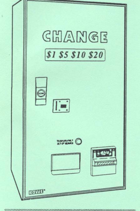
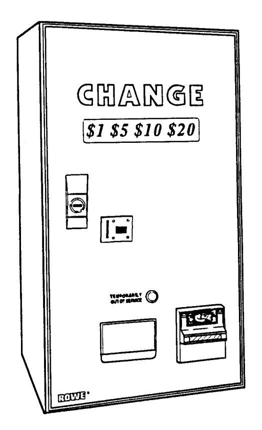
The Rowe® Century Series C-8 and C-10 Bill and Coin Changers can accept $1 thru $100 bills of United States currency. Using the appropriate bill acceptor, up to 7 denominations of any non-U.S. currency can be accepted. The unit can be programed by the operator to accept any or all of the bills. Figure 1-1 illustrates the major components of the Bill.
In addition, with the optional coin acceptor installed, up to 8 denominations of coins can be accepted.
The Bill Changer can dispense two different types of coins or tokens at a time. The number of coins dispensed for each bill and coin denomination accepted is programmable.
The C-8 and C-10 differ in height and coin hopper capacity. The C-8 is 32" high and can hold up to 4,200 U.S. Quarters. The C-10 is 33-7/8" high and can hold up to 6,800 U.S. quarters.
FEATURES
- . A microcomputer inside the Bill Changer monitors system status, accepts credit inputs from the bill acceptor or coin acceptor (when used), and controls the change dispensing functions.
- . Modular assemblies are featured for fast field substitution.
- . Setup and programming options are easily changed using the MODE, UP and DOWN pushbutton switches.
- . The removable coin hoppers permit rapid bulk loading of coins.
GENERAL OPERATION
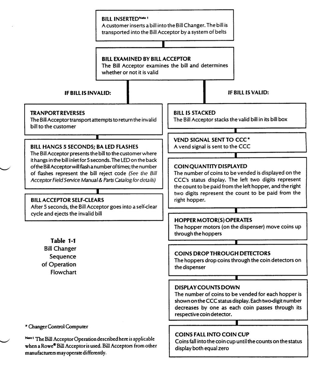
The Bill Changer Sequence of Operation Flowchart ( Table 1-1, opposite ) gives an overview of the Bill Changer sequence of operation, from the time that a bill is inserted into the changer until coins fall into the Coin Cup. For detailed information regarding the location and function of individual Bill Changer components, refer to System Components , which follows.
SYSTEM COMPONENTS
Refer to Figure 1-1 for placement of each of the following Bill Changer components:
Figure 1-2 Bill Acceptor
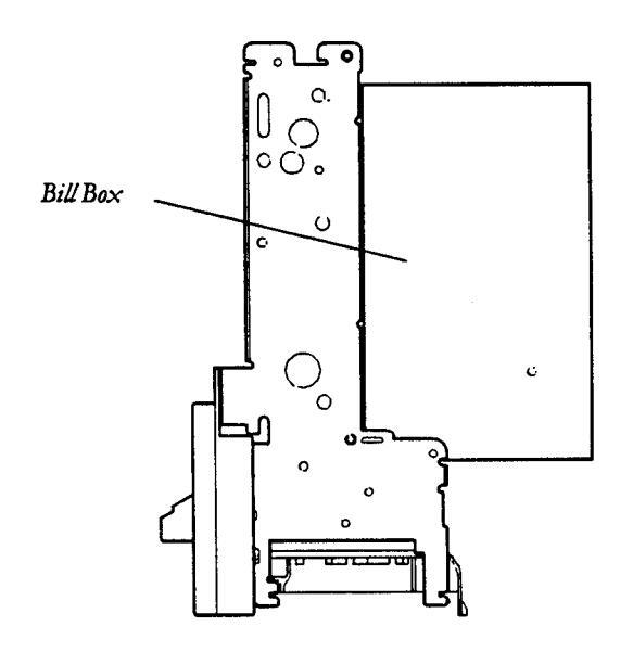
BILL ACCEPTOR*
The bill acceptor accepts and validates various denominations of bills depending on the bill acceptor and its setup. It stacks valid bills in a bill box that opens for easy bill removal. The bill acceptor mounts on the back of the Bill Changer door.
For specific bill acceptor information refer to the bill acceptor field service manual and parts catalog included with the Bill Changer.
* Rowe® Bill Acceptor pictured. Your changer may be equipped with an Acceptor from another manufacturer.
Bill Changer Sequence of Operation Flowchart
DISPENSER
The Bill Changer coin dispenser (Figure 1-3) contains the coin detector system and the hopper motors. The dispenser mounts on brackets on either side of the cabinet.
The coin detector system - one for each hopper - consists of an LED and a phototransistor, which "count" the coins as they exit the hopper and fall through the upper coin chute into the coin cup.
The hopper motors engage sprockets that drive the hopper. The 110 VAC motors are controlled by the CCC.
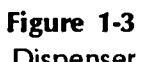

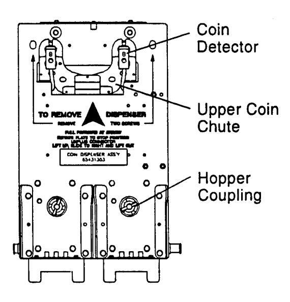
Figure 1-4 Hopper
HOPPER
The Bill Changer contains two hoppers (Figure 1-4), which mount on the front surface of the dispenser assembly and pivot out for easy removal.
The hoppers transport coins to their respective coin detector and then the upper coin chute by means of a chain conveyor driven from below by a sprocket. The chain picks up coins from the bottom of the hopper and carries them up to the top, where they fall through the upper chain guide ring and through the coin detector system.
The hopper chain follows a serpentine path that causes excess coins to fall back into the hopper. This ensures that only one coin per pin enters the coin counting area.
An agitator, which is mounted on the drive shaft inside the hopper, agitates the coin load to minimize coin jams in the hopper and to ensure efficient coin pick up. The hopper also contains the low coin sensor antenna and circuit hoard.
NOTE:
The low coin sensor alerts the computer when the number of coins in a hopper falls below a certain level.
The Bill Changer uses a low coin sensing system to detect when either hopper is low on coins. With this system, the operator does not have to program the computer with the number of coins that have been added to the hopper. When the hopper is loaded, the sensing circuit will automatically signal the computer that coins are present. As the hopper is emptied via the normal changemaking process, eventually the level of coins will fall below the threshold required by the low coin sensing circuit. This circuit will then signal the computer that the low level has been reached.
Each hopper has its own sensing circuit. The sensing circuit is mounted on the front surface of the coin hopper with electrical connections made through high pressure contact springs on the dispenser assembly. Because there are no elements inside the hopper to contact the coins, there is absolutely no impact on hopper operation and no degradation of the sensor due to contamination deposited by the coins themselves.
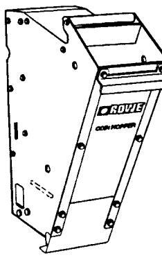
CHANGER CONTROL COMPUTER (CCC)
The Changer Control Computer (CCC, Figure 1-5 ) mounts on the back wall inside the changer cabinet. The CCC contains a microcomputer that controls and/or monitors all of the major functions of the Bill Changer, including communication with the Bill Acceptor and change dispensing functions. It also contains the following controls and displays:
Status Display
When the CCC is initially switched from the NORMAL to PROGRAM position, the status display will show Pro 9.
NOTE:
The four character LED status display window displays the many Bill Changer programming and self-diagnostic features described in this manual. See Section 4 for detailed programming information; see Section 6 for error code meanings.
Service and Control Switches
The Bill Changer's service features and programming options are controlled by three push button switches and one slide switch. The descriptions that follow are introductory. Refer to the detailed procedures and instructions in Section 4 for specific programming information.
PROGRAM/NORMAL Slide Switch
Selects either the NORMAL operating position or the PROGRAM position:
PROGRAM Position - Allows you to inspect and/or change Bill Changer setup information. This information is displayed on the status display and is selected and changed by using the MODE, UP and DOWN buttons.
NORMAL Position - Places the changer in a standby condition waiting to give change for a valid bill or coin while the CCC monitors all systems. While in standby, a dash moves from left to right across the 4-character status display.
MODE BUTTON
The MODE button is used to step through the setup options.
UP BUTTON
Increases the displayed value.
DOWN BUTTON
Decreases the displayed value.
TEMPORARILY OUT OF SERVICE LAMP
The temporarily out of service lamp ( Figure 1-1 ) is located on the Bill Changer door above the coin cup. It lights when the changer is low or out of change, or if the CCC has detected a malfunction.
Reset the Bill Changer by pushing the UP and DOWN buttons simultaneously on the CCC while the PROGRAM/NORMAL switch is in the NORMAL position. If the error has been corrected, the out of service lamp will go out and a dash will move from left to right accross the 4-character status display. See Section 6 for detailed troubleshooting information.
ELECTRICAL BOX
The Electrical Box (Figure 1-6), located inside the Bill Changer cabinet, houses the following electrical components:
The ON/OFF switch controls all power to the machine.
A 5 amp circuit breaker protects the power line to the bill changer.
An EMI filter (ElectroMagnetic Interference filter) removes undesirable electrical noise from the incoming power line.
The Money Counter is non-resettable, and indicates the amount of money handled by the changer.
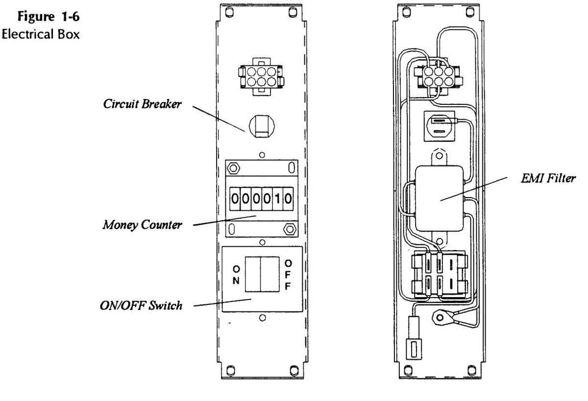
Front View
Back View
SECTION 2: INSTALLATION
INTRODUCTION
NOTE:
For both safety and security reasons, Rowe® strongly recommends that the Bill Changer be securely anchored to a wall or sturdy countertop. Please follow the mounting instructions provided in this manual.
This section provides instructions for installing the Century Series Bill Changers. To prevent theft, or the possibility of damage or injury should the Bill Changer fall, Rowe® strongly recommends that the Bill Changer be securely anchored to a wall or a sturdy countertop1. The instructions that follow provide directions for a secure installation.
Before you begin any installation, be sure that a power source is available and that the changer can be mounted level. Choose a location that is easily accessible to customers, with enough room to open the Bill Changer door for convenient service.
Be sure that you read and understand the warnings and instructions in Power Connection, page 2-6, before making any electrical connections to the Bill Changer.
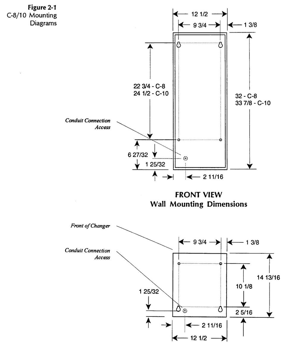
BILL CHANGER MOUNTING & SPECIFICATIONS
Figure 2-1 illustrates the Bill Changer mounting requirements and specifications, and provides dimensions for drilling.
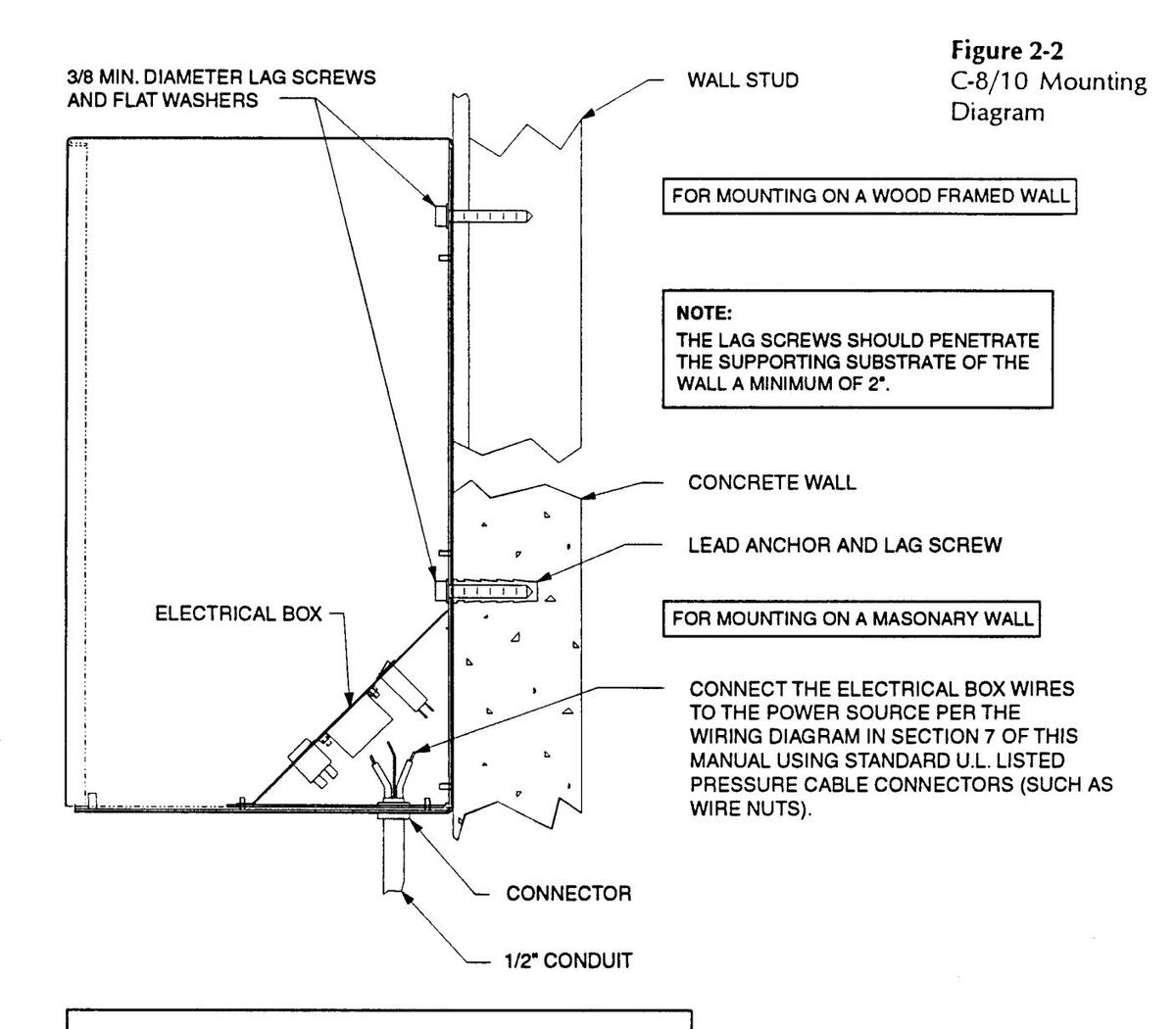
To mount the Bill Changer, use four 3/8" minimum diameter lag screws (with flat washers) that are long enough to penetrate the counter or supporting surface of the wall at least 2 inches. For wood frame mounting, screw directly into the wall studs. For mounting to concrete or masonry walls, use lag screws with lead anchors.
If the mounting surface is not even, you may need to add spacer washers between the mounting surface and the Bill Changer until the Bill Changer is level.
1 Rowe® also offers two different mounting bases as options. See the Accessory Kits section for details.
BOTTOM VIEW Table or Countertop Mounting Dimensions
WARNING:
BE SURE THAT YOU READ AND UNDERSTAND THE WARNINGS AND INSTRUCTIONS IN THIS SECTION OF THE MANUAL BEFORE MAKING ANY ELECTRICAL CONNECTIONS.
THE CONDUIT CAN BE INSTALLED THROUGH THE BOTTOM OR THROUGH THE BACK BY REVERSING THE ELECTRICAL PLATES. THE POSITION OF THE POWER CORD CAN BE CHANGED IN THE SAME MANNER.
C-8/10 POWER REQUIREMENTS: 120 VAC (MIN. 105 VAC), 60 Hz, 4 Amps. SHIPPING WEIGHT: 134/140 lbs. (220 or 240 VAC, 50 HZ optional), 2 Amps.
POWER CONNECTION
Always obey local codes and ordinances when making Power connection.
LINE CORD
On 120 VAC models, the Bill Changer power cord can be plugged into any standard three-hole 120 VAC outlet. Do not connect your Bill Changer using a two-pronged grounding adaptor. For 220V/240 VAC operation, install an appropriate connecting plug for your location, follow local safety codes and regulations, and make an earth connection to the case if allowed. To avoid possible voltage spikes that might effect the Bill Changer, do not operate any other high-wattage equipment on the same circuit with the Bill Changer.
The line cord comes factory installed through the back of the changer. Some installations require that the position of the cord be changed to run through the bottom of the changer. This can be done by removing the screws that hold the electrical box in place and reversing the electrical plates underneath ( Figure 2-2 ).
CONDUIT
If the changer is rigidly mounted to a wall, U.L. requirements specify that a direct power connection be made to the changer through a rigid, 1/2 inch conduit.
If a conduit is required for your installation, remove the nuts that hold the electrical box in place, and disconnect the standard line cord and strain relief. The conduit connector will run through the 7/8" diameter round hole in the electrical plate. Position the electrical plates so that the conduit will run either out the bottom or the back of the changer — whichever suits your installation — while blocking off the unused hole.
To install the conduit, cut the connectors of the line cord leaving three inches of wire on each connector. Connect these electrical box wires to the power source per the wiring diagram in Section 7 of this manual using standard U.L. listed pressure cable connectors (such as wire nuts).
CAUTION:
To avoid serious electrical shock, disconnect power at the source before making any electrical connections.
CAUTION:
To avoid the hazard of serious electrical shock and/or damage to the Bill Changer, direct wiring to the Bill Changer should only be attempted by a person familiar with proper electrical wiring procedures.
Bill Acceptor Installation and Setup
If you purchased your Century Changer without a Rowe Bill Acceptor Installed, you will need to install the Bill Acceptor into the Changer. Align the Bill Acceptor that you have chosen over the four mounting studs on the door, and secure using the four Keps Hex head nuts provided with the changer.
Harness connections must then be made between the Bill Acceptor and the Changer Control Computer. The following harnesses are provided:
| Harness Part Number | Bill Acceptor(s) |
|---|---|
|
45108203 - Data
45108204 - Power |
Mars
®
VN2501, LE3801, AL4L1
Coinco ® BA30SA, BA50SA |
| 45108205 | CashCode ® CSR-Series, CSB-Series |
| 45108207 | AstroSystems ® VS2C Series |
The Bill Acceptor must be set up to communicate in the Serial Interface mode. The DIP switch settings shown below must be used; other switches may be set as desired.
| Model | Switch Settings | |
|---|---|---|
| Mars® |
AL4: Bank 1 - 1, 3, 4, 5 ON, Remainder OFF H
GL4C: Bank 1 - 3, 4, 5 ON, Remainder OFF H LE3801: Bank 1 - 8 OFF VN2501: Bank 1 - 1 thru 6 ON, 7 and 8 OFF |
Bank 2 - All OFF
Bank 2 - All OFF |
| Coinco® | BA30S, BA50S: 3 thru 8 ON | |
| CashCode® | Switch 1 - 8 OFF | |
| AstroSystems® |
VS2C: DIP 1 - 8 ON, Remainder OFF
DIP 2 - 7 ON, Remainder OFF |
For reference purposes, the Rowe CBA-4 requires the use P/N 45108201 Harness and the RBA-7 requires a P/N 45108208 Harness. Refer to the respective Interface Instructions manual and set the acceptors for the Serial Interface with Handshaking mode of operation.
SW#2 ONLY CBA-2 25530230 CBA-4 65073230 PRA- m 65079044 SW1-2 ON, 5w2+23,45 ON
25554501
SECTION 3: LOADING & AUDITING
INTRODUCTION
This section provides instructions for loading and unloading the Century Series coin hoppers.
LOADING THE BILL CHANGER
NOTE:
The hoppers may be loaded with coins or tokens within the diameters specified – but different coin types may not be mixed in the same hopper.
Refer to Section 4: PROGRAMMING to change the default coin payout.
Loading the hopper is easiest when the coins are delivered via a coin bag. Hopper capacities vary depending on the machine model, hopper type, and coin/token size. Tables 3-1 and 3-2 give approximate capacities.
C8 Hopper Capacities
| Hopper Type |
Dimes
17.9mm |
Nickels
21.21mm |
Quarters
24.25mm |
.984"
Tokens 25mm |
SBA $1/
Canadian $1 26.5mm |
Canadian $2
(1.10") 27.95mm |
1.125"
Tokens 28.57mm |
|---|---|---|---|---|---|---|---|
| 65094907 (Small Coin) | 5000 | 2400 | 2100 | N/A | N/A | N/A | N/A |
| 65094908 (Large Coin) | N/A | N/A | 1850 | 1600 | 1400 | 1200 | 1000 |
Table 3-1
| CIVITOPPET Capacities | C10 | Hop | per Ca | pacities |
|---|
| Hopper Type |
Dimes
17.9mm |
Nickels
21.21mm |
Quarters
24.25mm |
.984*
Tokens 25.0mm |
SBA $1/
Canadian $1 26.5mm |
Canadian $2
(1.10") 27.95mm |
1.125"
Tokens 28.57mm |
|---|---|---|---|---|---|---|---|
| 65092903 (Small Coin) | 8000 | 4000 | 3400 | N/A | N/A | N/A | N/A |
| 65092904 (Large Coin) | N/A | N/A | 3200 | 3000 | 2200 | 2100 | 1800 |
Table 3-2
LOADING THE HOPPERS
Refer to Figure 3-1 and load the hopper as follows:
- 1. Open front door and pull the hopper(s) out against the bail rod.
- 2. Twist the top of a full coin bag one full turn. Grasp the twisted top with one hand and hold the bottom of the bag with the other. Invert the bag and insert the top into the mouth of the hopper.
- 3. Slowly release the twist as the bag empties. Avoid spilling coins into the changer. When the bag is almost empty, grasp it at the bottom and shake it to dislodge coins tucked in the folds of the bag.
- 4. Repeat Steps 2 and 3 with the second hopper.
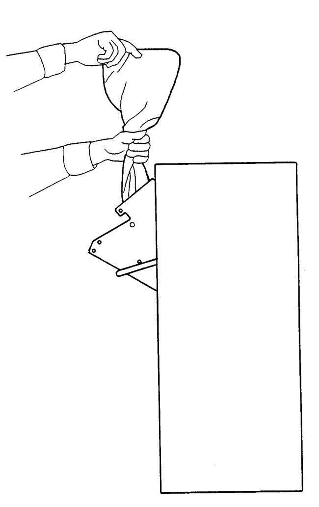
Figure 3-2 Emptying the Hopper
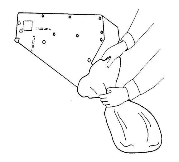
UNLOADING THE HOPPERS
- 1. Open the door.
- 2. Lift the right side of the bail rod upward until it disengages from the cabinet.
- 3. Pull the right side of the rod out of the hole and remove the rod completely from the cabinet.
- 4. Carefully pivot the hopper outward until a coin bag can be installed over the top of the hopper. Hold the bag tightly and slowly tip the hopper down until it contacts the rap rod. Figure 3-2 .
- 5. Move the hopper up and down on its pivots a few times to completely dislodge all of the coins in the hopper.
- 6. Repeat Steps 4 and 5 with the second hopper.
Auditing
There are three pieces of information needed in order to thoroughly audit your bill changer. The amount of cash removed from the bill box (and coin box if you have a coin acceptor) should match the difference in money counter readings. Also, the difference between the number of coins (or tokens) initially loaded in the hopper and the remaining number should match the total cash removed multiplied by the number of coins or token paid per unit of cash input. An example follows:
Initially
Accepts: $1, $5, $10 and 25¢ Payout: Tokens (.984") (1 for 25¢, 4 for $1, 24 for $5, 50 for $10) Initial Hopper Load: 6,000 coins (3,000 each hopper) Initial Counter Reading: 047233
At Service Interval
Intake Check: Removed:
40 x .25 = $ 10 154 x $1 = $154 105 x $5 = $525 38 x $10 = $380 Total Intake = $1069
Counter Reading: 048302 Counter Difference 48302 - 47233 = 1069 ✓
Coin Count Check:
Hopper Contents: 924 Tokens (Remaining in both hoppers) Should have dispensed: 40 x 1 = 40 154 x 4 = 616 105 x 24 = 2520 38 x 50 = 1900 Total = 5076 Actual dispensed: 6000 (initial) - 924 (remaining) 5076 ✓
SECTION 4: PROGRAMMING
PROGRAMMING THE CENTURY 8 AND CENTURY 10 BILL AND COIN CHANGERS
There are three pushbuttons and one slide switch on the controller board. These are used to perform all programming activities.
The Program switch is positioned to the left for normal operations. In this position, if everything is normal, a dash will walk across the four displays, from left to right. If an error has occurred, an error code will be displayed, indicating what has caused the error. See Section 6 for Troubleshooting information.
Sliding the Program switch to the right will place the controller in the programming mode. In this mode the type of coin acceptor, bill validator, mode of operation, and payouts for each bill and coin may be set or adjusted.
The pushbutton switch on the left is the mode switch and is used to step through the options. The middle and right hand switches are used for adjusting the options choices or payout amounts. The middle switch steps up and the right switch steps down.
The middle and right switches are also used to reset any error codes. See Section 6 for details.
PROGRAMMING
NOTE:
Use the Serial setting for all applications. All bill validators must be 120 VAC or 12VDC. An additional transformer (not supplied by Rowe) is required for 24VAC operation.
Slide the normal / program switch to the right. The display will show Prog.
Press the mode button once for each option to be programmed. The options appear on the display in order as shown below. When a setting has been changed, always press the mode button at least once to "save" the setting.
Coin Acceptor Settings
This option selects the type of Coin Acceptor installed in the machine. Using the up and down pushbuttons choose the appropriate type.
- ER D No Coin Acceptor is installed
- CR | A Standard Coin Acceptor is installed. (4 coin types max.)
- [R] 2 A Special Electronic Coin Acceptor is installed. (8 coin types max.)
- Coin type 1. This option selects the coins to be accepted. Use the up and down pushbuttons to enable or disable the displayed coin type. If the value is set to 0, the changer will not recognize that coin. If the value is set to 1, that coin will be recognized, and the change will be paid. Be sure to set the coin acceptor to accept only those coins you want accepted as the changer controller cannot control which coins the coin acceptor will accept and send to the cashbox.
- [2] [] Coin type 2. Program as in [] [] above.
- [] Coin type 3. Program as in [] above.
- [] Coin type 4. Program as in [] [] above.
- [5] [] Coin type 5. Program as in [] [] above.
- [5] [] Coin type 6. Program as in [1] [] above.
- [7] Coin type 7. Program as in [1] above.
- [1] Coin type 8. Program as in [1] above.


If the Coin Acceptor type was set to 0 no acceptor installedthese options will not be displayed. If the Coin Acceptor type was set to type 1, only 27 through 24 will be displayed.
NOTE:
Coin Acceptor Setup Information
If you purchased your Century Changer with a Coin Acceptor Installed, the following setup information is required.
Mechanical Coin Acceptor
With this system, a simple 3.5" acceptor will deliver a valid coin to the coin box, actuating a microswitch as it passes out of the acceptor. The harness from P1 of the Control Computer will deliver the signal to the Coin Type 1 input line. The computer will assure that the signal is between 15 and 175 milliseconds in duration before credit is issued.
The coin lockout solenoid, also connected to P1 of the Control Computer, will "drop out" and cause inserted coins to be redirected to the coin cup if: the machine is turned off or has no input power applied; if the machine is in the process of dispensing coins; or if the machine is otherwise out of service.
If you are using this system, select Coin Acceptor Type 1 and follow the instructions below.
For US/Canadian Machines:
The coin acceptor harness is shipped to you such that a valid coin is accepted as Coin Type 1. This credit signal will cause the money meter to advance once for every 4 coins accepted. This setting would be used if 25¢ coins are accepted. If you are accepting $1 coins, move the brown credit wire (See Figure 4-1) connected to the Control Computer at P1, pin 11 over to pin 10 (Coin Type 2) and program the computer to accept Coin Type 2. This credit signal will cause the money meter to advance one count for each coin accepted. If you want to accept $2 coins, move the brown credit wire to P1, pin 8 (Coin Type 4) and program the computer to accept Coin Type 4. This credit signal will cause the money meter to advance two counts for each coin accepted. Credit received as Coin Type 3 will never advance the money meter.
For Non-US Machines:
Program the computer to enable Coin Type 1, and set the payout accordingly. The money meter will advance based on other settings.
Electronic Coin Acceptor
Rowe also offers a Mars Cashflow 330 electronic coin acceptor option. This acceptor has the ability to accept many different denominations of coins from many different countries. The US/Canadian version of this acceptor can be enabled to accept 5¢, 10¢, 25¢ and $1 coins from each country, plus the Canadian $2 coin. This programming is done using DIP switches or with a Route Alpha Terminal available from Mars.
When connected to the P1 connector of the Control Computer, valid coins will provide credit to the Changer as follows:
| COIN | COIN TYPE |
| US 25¢ | 5 |
| Canadian 25¢ | 3 |
| US $1 (SBA) | 6 |
| Canadian $1 | 4 |
| Canadian $2 | 7 |
Bill Acceptor Settings
b R l This option selects the type of Bill Acceptor installed in the machine. Using the up or down pushbuttons select the appropriate type.
l Pulse type Bill Acceptor is installed. (2 bill types max.) 2 Rowe® Serial type Bill Acceptor is installed. (7 bill types max.)
3 Non-Rowe Serial type Bill Acceptor is installed.
Do not use bA / in the Century 8 or Century 10. (Used in Century 2 only). Use bR 2 for Rowe® CBA-4 and RBA-7. Use bR 3 for all other bill acceptors.
NOTE: If the bR ∃ option is not available in your control's menu, choose bR 2 . bR ∃ is present in Software Revision 2.3 and higher and has improvements in the area of Bill Acceptor fault handling.
- I This option selects the bills to be accepted. Use the up and down pushbuttons to enable or disable the displayed bill type. If the value is set to 0, the changer will not recognize that bill. If the value is set to 1, that bill will be recognized, and change will be paid. There is a maximum of 7 bills for the serial type Bill Acceptors.
- 62 I Bill type 2. Program as in 6 ! I above.
- b 3 0 Bill type 3. Program as in b 1 above .
- 64 0 Bill type 4. Program as in 61 0 above.
- 65 0 Bill type 5. Program as in 61 0 above.
- 65 D Bill type 6. Program as in b / D above.
- b7 D Bill type 7. Program as in b ! D above.
Coin Ratio Settings
U.S. and Canadian Changers, Control Computer P/N 45085902 -
This option sets the operating mode for the two coin hoppers. There are only two settings that should be used, although other selections are shown in the setup menu.
Er 1
Choose this setting if the coins in the hoppers are of different values, or if you do not want the computer to operate in the MC Mode as described below.
The maximum payout in this mode is 99 coins or tokens from each hopper.
E-1.1.
Choose this setting if the coins in the hoppers are of the same value and you want the changer to use the hoppers interchangeably to deliver coins to the customer. If one hopper should become low on coins or experience a failure, the other hopper will be used to pay the customer.
If both hoppers are functioning properly, they will be used equally to deliver change. This is referred to as "MC Mode".
The maximum payout in this mode is 99 total coins or tokens.
Do not use any of these settings:
[r 0 , [r 2 , [r2.5 , [r 4 , [r 5 , [r]0.
Non - U.S. and Canadian Changers, Control Computer P/N 45085903 -
This option selects the Coin Ratio between the coins in the two coin hoppers. The ratio is between the left hopper, which must contain the coin of the smaller monetary value, and the right hopper, which must contain the coin of the higher monetary value. Use the up and down pushbuttons to select the appropriate Coin Ratio.
Example: The left hopper contains .10 coins and the right hopper contains .25 coins, set the Coin Ratio to 2.5.
Do not use [r ].
- Er (1:1) Same value coin in each hopper. Each hopper pays a distinct number of coins as programmed. See Er (1, 1, below.
- □ (1:2) The coin in the right hopper has 2 times the value of the coin in the left hopper.
- L ~ Z .5 (2:5) The coin in the right hopper has 2.5 times the value of the coin in the left hopper.
- L r 4 (1:4) The coin in the right hopper has 4 times the value of the coin in the left hopper.
- [1:5] The coin in the right hopper has 5 times the value of the coin in the left hopper.
- [r] (1:10) The coin in the right hopper has 10 times the value of the coin in the left hopper.
- Erl.1. (1:1) Choose this setting if the coins in the hoppers are of the same value and you want the changer to use the hoppers interchangeably to deliver coins o the customer. If one hopper should become low on coins or experience a failure, the other hopper will be used to pay the customer. If both hoppers are functioning properly, they will be used equally to deliver change. This is referred to as "MC Mode".
The maximum payout in this mode is 99 total coins or tokens.
Money Meter Settings
This menu option appears only with non – U.S. and Canadian Changers, those using Control Computer P/N 45085903 –
P ⊂ □□This option selects the correct number of pulses to send to the money meter.<br/>The Pulse Count should be set to the number of coins from the left hopper<br/>that would be required to advance the Money meter 1 count. For example if<br/>the left hopper contains 50 centavo coins and it is desired that the money<br/>meter count in pesos, the pulse count should be set to 2 (2 * 50c = 1 peso).<br/>Even in the case where you might choose to pay no left hopper coins for a<br/>certain input, the money meter value will be calculated - using the Pc and Cr<br/>settings - and the meter will advance properly.
Use the up and down pushbuttons to select the appropriate setting. Any value between 00 and 99 may be set.
Note: Using the P c and the C values the money meter will advance properly regardless of the number or mix of coins used to pay for any particular bill or coin inserted if the payout combinations add together to exactly equal the input value. If you are paying out tokens and provide a bonus for higher input denominations, the money meter will not exactly match the amount of money accepted by the changer.
Coin Level Settings
- LI [].[] This option informs the controller of the minimum number of coins remaining in the left hopper when the low-level sensor signals that a low level has been reached. Use the up and down pushbuttons to set this option to an appropriate value. Any value between 60 and 990 may be set in 10 coin increments. Note the position of the illuminated decimal point on the display, indicating the left hopper level is being set.
- L / DD. This option informs the controller of the minimum number of coins remaining in the right hopper when the low-level sensor signals that a low level has been reached. Use the up and down pushbuttons to set this option to an appropriate value. Any value between 60 and 990 may be set in 10 coin increments. Note the position of the illuminated decimal point on the display, indicating the right hopper level is being set.
- L | D.D. This option informs the controller of the number of coins remaining in either hopper, when the low-level sensor trips. Use the up and down pushbuttons to set this option to an appropriate value. Any value between 60 and 990 may be set in 10 coin increments. Note that two decimal points on the display are illuminated ndicating the machine is set for MC MODE([r | .| .)], and the level for both hoppers is being set.
NOTE: This option will only be displayed if the Coin Ratio is set to MC MODE ( [ri , i , i ).
These settings are used so that you may dispense the maximum number of coins or tokens, without the possibility of shortchanging a customer, before the changer goes out of service for lack of coins. The number you program here lets the computer know how many coins remain in the hopper when the coin level sensing system signals a low level.
8.8.88 The decimal points on the two leftmost displays indicate the state of the lowlevel sensors. The decimal point on the far-left display indicates a low-level condition exists in the left hopper, when lit. The decimal point on the second display from the left indicates a low-level condition exists in the right hopper, when lit.
The setting depends on the type of hopper being used and the type of coin or token loaded. To choose the correct setting, use one of the tables below based on the hopper and coins being used:
Recommended Low Coin Settings for Century 8
| SMALL COINS HOPPER (65094907) | ||||
|---|---|---|---|---|
|
US 5¢
(21.21mm) |
US 10¢
(17.9mm) |
US 25¢
(24.25mm) |
.880" Token
(22.35mm) |
|
| 110 | 400 | 110 | 130 | |
| LARGE COINS TOKEN HOPPER (65094908) | |||||
|---|---|---|---|---|---|
|
US 25¢
(24.25mm) |
US SBA Dollar
(26.5mm) |
.984" Token
(25mm) |
Can. $2/1.125 Token
(28mm) |
||
| 100 | 70 | 90 | 60 | ||
Recommended Low Coin Settings for Century 10
| SMALL COINS HOPPER (65092903) | ||||
|---|---|---|---|---|
| US 5¢ US 10¢ US 25¢ .880" Token (21.21mm) (17.9mm) (24.25mm) (22.35mm) | ||||
| 200 | 500 | 200 | 200 | |
| LARGE COINS TOKEN HOPPER (65092904) | ||||
|---|---|---|---|---|
|
US 25¢
(24.25mm) |
US SBA Dollar
(26.5mm) |
.984" Token
(25mm) |
Can. $2/1.125 Token
(28mm) |
|
| 160 | 120 | 140 | 80 | |
There is a second limitation on the number you set into the computer – it must be at least 30 higher than the highest number of coins or tokens to be paid to the customer.
You must choose the hoppers, coins or tokens used, and/or the operating mode as appropriate in order to maintain this 30 coin margin.
Coin Payout Settings
These functions will set the number of coins dispensed from the hoppers for the input coin types set earlier. If a coin type is disabled, its payout amount setting will not be displayed.
Non-MC Mode
- I ⊂ □.□ Left Hopper Payout for Coin type 1. This number represents the number of coins dispensed from the left hopper. Use the up and down pushbuttons to set the number to the desired value. Any value between 00 and 99 may be set. If a coin type was disabled, its programming will not be displayed. Note the position of the illuminated decimal point on the display, indicating the left hopper payout amount s being set.
- I c II. Right Hopper Payout for Coin type 1. This number represents the number of coins dispensed from the right hopper. Use the up and down pushbuttons to set the number to the desired value. Any value between 00 and 99 may be set. Note the position of the illuminated decimal point on the display, indicating the right hopper payout amount is being set.
- Payout for Coin type 2, left hopper. Program as in above.
. Payout for Coin type 2, right hopper. Program as in . above.
Payout for Coin type 3, left hopper. Program as in above.
Payout for Coin type 3, right hopper. Program as in . above.
Payout for Coin type 4, left hopper. Program as in above.
. Payout for Coin type 4, right hopper. Program as in . above.
- 5 c 0.0 Payout for Coin type 5, left hopper. Program as in / c 0.0 above.
- 5 c 00. Payout for Coin type 5, right hopper. Program as in . above.
- 5 c 0.0 Payout for Coin type 6, left hopper. Program as in / c 0.0 above.
- 5 c 00. Payout for Coin type 6, right hopper. Program as in / c 00. above.
- 7 c 0.0 Payout for Coin type 7, left hopper. Program as in / c 0.0 above.
- 7c II. Payout for Coin type 7, right hopper. Program as in / c II. above.
- B c D.D Payout for Coin type 8, left hopper. Program as in above.
. Payout for Coin type 8, right hopper. Program as in . above.
MC Mode
1 ⊂ □.□. This option sets the number of coins dispensed from both the left and the right hoppers for the coin types set earlier. Note that two decimal points are illuminated indicating the machine is set for MC MODE ([ ⊂ | .| .). See above for programming.
NOTES:
- 1. This option is not displayed unless MC MODE is enabled.
- 2. The maximum number of coins that can be paid out is 99 in the MC MODE.
- 3. The above option will repeat for each type of coin accepted, in MC MODE.
Bill Payout Settings
These functions will set the number of coins dispensed from the hoppers for the input bill types set earlier. If a bill type is disabled, its payout amount setting will not be displayed.
Non-MC Mode
- 1 b0.0 Left Hopper Payout for Bill type 1. This number represents the number of coins dispensed from the left hopper. Use the up and down pushbuttons to set the number to the desired value. Any value between 00 and 99 may be set. If a bill type was disabled, its programming will not be displayed. Note the position of the illuminated decimal point on the display, indicating the left hopper payout amount is being set.
- 1 600. Right Hopper Payout for Bill type 1. This number represents the number of coins dispensed from the right hopper. Use the up and down pushbuttons to set the number to the desired value. Any value between 00 and 99 may be set. Note the position of the illuminated decimal point on the display, indicating the right hopper payout amount is being set.
- 260.0 Payout for Bill type 2, left hopper. Program as in / 60.0 above.
- 2600. Payout for Bill type 2, right hopper. Program as in / 600. above.
- 360.0 Payout for Bill type 3, left hopper. Program as in / 60.0 above.
- 3600. Payout for Bill type 3, right hopper. Program as in / 600. above.
- 460.0 Payout for Bill type 4, left hopper. Program as in / 60.0 above.
- 4600. Payout for Bill type 4, right hopper. Program as in / 600. above.
- 560.0 Payout for Bill type 5, left hopper. Program as in / 60.0 above.
- 5600. Payout for Bill type 5, right hopper. Program as in / 600. above.
- 560.0 Payout for Bill type 6, left hopper. Program as in / 60.0 above.
- 5500. Payout for Bill type 6, right hopper. Program as in 1 500. above.
- 760.0 Payout for Bill type 7, left hopper. Program as in 1 60.0 above.
- 7600. Payout for Bill type 7, right hopper. Program as in / 600. above.
- 860.0 Payout for Bill type 8, left hopper. Program as in 1 60.0 above.
- 8600. Payout for Bill type 8, right hopper. Program as in / 600. above.
MC Mode
1 b0.0. This option sets the number of coins dispensed from both the left and the right hoppers for the bill types set earlier. Note that two decimal points are illuminated indicating the machine is set for MC MODE (2 r l .l .). See above for programming.
NOTES:
- 1. This option is not displayed unless MC MODE is enabled.
- 2. The maximum number of coins that can be paid out is 99 in the MC MODE.
- 3. The above option will repeat for each type of coin accepted, in MC MODE.
| Prog | Programming Examples | |||||
|---|---|---|---|---|---|---|
| Exan | nple | e 1: | ||||
| Гурі | cal f | or US/Canadian C-8 Model using US | 5 money | |||
|
Coin
Bills Hopp Coin |
Coin accepted: $1 Bills accepted: $1.00, $5.00, $10.00, $20.00 Hoppers: Left: NDQ (65094907), Right: $1/Tokens (65094908) Coins Used: 25¢ in left hopper, SBA $1 in right hopper | |||||
| Мас | hin | e settings: | ||||
| C A | 2 |
Electronic coin acceptor installed.
(Mars ME330) |
LI 0.0 |
Countdown starts at 100 coins
after low level sensor trips for |
||
| 58 | 2 | Serial type Validator installed. | חרחו | Countdown starts at 70 coins | ||
|
[]
[2 |
0
0 |
Coin value 1 not accepted.
Coin value 2 not accepted. |
after low level sensor trips for
right hopper |
|||
| Ξ3 | ۵ | Coin value 3 not accepted. | 60.4 | 4 x .25 = $1.00 | ||
| 54 | 0 | Coin value 4 not accepted. | 6000. | 0 x 1.00 = 0.00 | ||
| 5 | ۵ | Coin value 5 not accepted. | 160.4 | 4 x .25 = $1.00 | ||
| 56 | I | Coin value 6 accepted. | 1604. | 0 x 1.00 = 0.00 | ||
| 2 | ۵ | Coin value 7 not accepted. | 360.4 | 4 x .25 = $1.00 | ||
| 68 | ۵ | Coin value 8 not accepted. | ЭЬОЧ. | 4 x 1.00 = $4.00 | ||
| 57 | I | Bill value 1 accepted ($1.00) | 460.8 | 8 x .25 = $2.00 | ||
| 52 | ۵ | Bill value 2 not accepted ($2.00) | 4608. | 8 x 1.00 = $8.00 | ||
| 53 | I | Bill value 3 accepted ($5.00) | 5Ы.2 | 12 x .25 = $3.00 | ||
| 54 | l | Bill value 4 accepted ($10.00) | 561 7. | 17 x 1.00 = $17.00 | ||
| 55 | 1 | Bill value 5 accepted ($20.00) | end of pro | ogramming | ||
| 55 | ۵ | Bill value 6 not accepted ($50.00) | ||||
| 67 | ۵ | Bill value 7 not accepted ($100.00) | ||||
Er / Coins are of different values
Note: A C-10 Model would be setup exactly the same as the C-8, except for the Low Level Settings.
Example 2:
Typical for US/Canadian C-8 Model using Canadian money
| Coin accepted: | $2 |
|---|---|
| Bills accepted: | $5.00, $10.00, $20.00 |
| Hoppers: | Both $1/Tokens (65094908) |
| Coins Used: | $1 in left hopper, $2 in right hopper |
Machine settings:
| ER | 2 |
Electronic coin acceptor installed.
(Mars ME330) |
L060. | Countdown starts at 60 coins after low level sensor trips for |
|---|---|---|---|---|
|
Ь
Я
Г I |
2
П |
Serial type Validator installed. | כ.םכר |
ngnt nopper
2 x $1.00 = $2.00 |
|
53
53 |
0
0 |
Coin value 2 not accepted.
Coin value 3 not accepted. |
רכסר.
360.3 360.3 . |
0 x $2.00 = $0.00
3 x $1.00 = $3.00 1 x $2.00 = $2.00 |
|
C5
C5 |
0
0 0 |
Coin value 4 not accepted.
Coin value 5 not accepted. Coin value 6 not accepted. |
460.2
4604. |
2 x $1.00 = $2.00
4 x $2.00 = $8.00 |
|
ר כ
83 |
|
D |
Coin value 7 accepted.
Coin value 8 not accepted. |
560.4
5608. |
4 x $1.00 = $4.00
8 x $2.00 = $16.00 |
|
Ы
62 |
0
0 |
Bill value 1 not accepted ($1.00)
Bill value 2 not accepted ($2.00) |
end of pr | ogramming |
|
ЬЭ
ЬЧ |
|
| |
Bill value 3 accepted ($5.00)
Bill value 4 accepted ($10.00) |
||
|
65
65 |
I
П |
Bill value 5 accepted ($20.00)
Bill value 6 not accepted ($50.00) |
- 67 日 Bill value 7 not accepted ($100.00)
- Er / Coins are of different values
- L 27.2 Countdown starts at 70 coins after low level sensor trips for left hopper
Note: A C-10 Model would be setup exactly the same as the C-8, except for the Low Level Settings.
Example 3:
Typical for US/Canadian C-8 Model using US money.
Coin accepted:$1Bills accepted:$1, $5, $10, $20Hopper:Both $1/Tokens (65094908)Coins Used:.984 Tokens in each hopper
Machine settings:
- [R 2 Electronic coin acceptor installed. L09.0 (Mars ME330)
- BR 2 Serial type Validator installed.
- [1] D Coin value 1 not accepted.
- [] Coin value 2 not accepted.
- C B C Coin value 3 not accepted.
- L Y D Coin value 4 not accepted.
- [5] [] Coin value 5 not accepted.
- EB / Coin value 6 accepted.
- [7] [] Coin value 7 not accepted.
- CB D Coin value 8 not accepted.
- bl / Bill value 1 accepted ($1.00)
- bc 2 □ Bill value 2 not accepted ($2.00)
- B Bill value 3 accepted ($5.00)
- b님 / Bill value 4 accepted ($10.00)
- 65 / Bill value 5 accepted ($20.00)
- bb b b ill value 6 not accepted ($50.00)
- b7 [] Bill value 7 not accepted ($100.00)
- [r]. l. Coins are of same value and use MC Mode
Note: A C-10 Model would be setup exactly the same as the C-8, except for the Low Level Settings.
- Countdown starts at 90 coins after low level sensor trips for left hopper
- LUSD. Countdown starts at 90 coins after low level sensor trips for right hopper
- 550.4. 4 Tokens for $1
- 160.4. 4 Tokens for $1
- 362.4. 24 Tokens for $5
- 465.0. 50 Tokens for $10
- 569.5. 95 Tokens for $20
end of programming
Example 4:
Typical for Mexican C-8 Model
| Coin accepted: | 5 Peso, 10 Peso |
|---|---|
| Bills accepted: | 10, 20, and 50 Peso |
| Hopper: | Left: NDQ (65094907), |
| •• | Right: $1/Tokens (65094908) |
| Coins Used: | 1 Peso in left hopper, 2 Peso in right hoppe |
Machine settings:
| ER | 2 | Coin acceptor installed | LI 6.0 | Countdown starts at 160 coins |
|---|---|---|---|---|
| [] | I | Coin value 1 is accepted |
after low level sensor trips for
left hopper |
|
| 23 | I | Coin value 2 is accepted | 1 I YA | Countdown starts at 140 coins |
| ΕЭ | ۵ | Coin value 3 not accepted. | 20. | after low level sensor trips for |
| ĽЧ | ۵ | Coin value 4 not accepted. | right hopper | |
| E 5 | ۵ | Coin value 5 not accepted. | 1 0.3 | 3 x 1 = 3 |
| ΕБ | ۵ | Coin value 6 not accepted. | 1 601. | 1 x 2 = 2 |
| רכ | ۵ | Coin value 7 not accepted | 200.6 | 6 x 1 = 6 |
| C 8 | ۵ | Coin value 8 not accepted | 102. | 2 x 2 = 4 |
| ЬЯ | 2 | Serial type Validator installed | 1 60.6 | 6 x 1 = 6 |
| ы | 1 | Bill value 1 accepted ($10.00) | 1603. | 2 x 2 = 4 |
| 62 | 1 | Bill value 2 accepted ($20.00) | 260.4 | 4 x 1 = 4 |
| ЬЭ | 1 | Bill value 3 accepted ($50.00) | 2608. | 8 x 2 = 16 |
| ЬЧ | ۵ | Bill value 4 not accepted ($100.00) | 361.0 | 10 x 1 = 10 |
| Ь5 | ۵ | Bill value 5 not accepted ($200.00) | 3620 | . 20 x 2 = 40 |
| ЬБ | ۵ | Bill value 6 not accepted | end of p | rogramming |
| Ь٦ | ۵ | Bill value 7 not accepted | ||
| Er | 2 | Right hopper coin is 2 times value of left hopper coin |
P[0] Money meter increments for every 1 left hopper coin (peso)
Note: A C-10 Model would be setup exactly the same as the C-8, except for the Low Level Settings.
ERROR CODES
- Er / EEPROM error. Reprogram machine. If error repeats, replace controller board.
- Er 2 The bill acceptor accepted a bill that was not programmed. Program the bill acceptor the same as the changer.
- Er 3 Long pulse on bill acceptor credit line. Check for short to ground on credit line. Replace bill acceptor.
- Er 4 BA Fault. Check for full Stacker, or debris in bill acceptor. Replace bill acceptor.
- Er 5 Left hopper error. Check for coin jam, or binding parts in hopper. Verify that the left hopper motor is operating correctly.
- Er 5 Right hopper error. Check for coin jam, or binding parts in hopper. Verify that the right hopper motor is operating correctly.
- Er 7 Extra coin detected. Check brake stop pawl on hopper motors, replace or repair.
- Er B Left coin detector blocked. Clear debris. Clean or replace detector or LED.
- Er 9 Right coin detector blocked. Clear debris. Clean or replace detector or LED.
- Er / D Programming Error. Check programming. A setting is incorrect for conditions.
Example: A bill has been enabled, but the payout was not programmed.
- Erll MC_Mode error. One or both hoppers are at fault. Check for coin jam, or binding parts in hopper. Verify hopper motors are operating correctly.
- Erl 2 The changer is or was experiencing a low line voltage condition while dispensing coins. Check that the line voltage is maintained at 110 to 125 VAC. Check the Changer setup to be sure it is programmed as desired. An incorrect customer payout may have occurred.
- Er! 4 MC_Mode empty. The hoppers are empty. Refill hoppers.
- Er! 5 Left hopper empty. Refill left hopper.
- Erl 5 Right hopper empty. Refill right hopper.
- E 2! The computer experienced a problem while saving information in it's onboard
- Er 22 memory chip. The most likely cause for this would be a power loss during the
- Er23 programming process. Another possible cause could be a recurring low line voltage condition—See Er12 above.
- - Dashes walking through only first two LEDs. Check for stuck coin switch.
- ---- Dashes walking through all four LEDs—condition normal.
To clear most errors, press the up and down pushbuttons simultaneously, then release. To clear error 01 or 10, enter Program Mode and make the necessary corrections.
SECTION 5: MAINTENANCE & ADJUSTMENTS
INTRODUCTION
The modular design of the Century Series allows for fast field substitution and easy maintenance of changer components. This section provides instructions for removing Bill Changer components for service, and details mechanical maintenance procedures.
BILL ACCEPTOR
For specific Bill Acceptor information not included in this manual, refer to the Bill Acceptor Field Service Manual and Parts Catalog included with the Bill Changer.
REMOVING A JAMMED BILL – Rowe® Bill Acceptor Only
To remove a jammed bill from the Bill Acceptor, first try to determine where the bill is jammed in the transport.
CAUTION:
Always turn the Bill Changer power to off before turning the Bill Acceptor gears by hand. Be careful not to pinch your fingers between the gears.
Open the bill box and determine if the bill can be reached. If necessary, the gear on the side of the transport can be turned by hand, forward or reverse, to remove the bill.
If the bill is jammed near the bill inlet, first try removing it by turning the transport gear by hand. If this does not free the bill, you will need to remove the inlet. Follow the instructions in this section to remove the transport from the Bill Changer, then refer to Section 3 of your Bill Acceptor manual for instructions to remove the bill inlet.
If bills jam frequently, refer to the Bill Jamming Checklist in Section 3 of your Bill Acceptor manual.
If your Bill Changer is equipped with a non-Rowe Bill Acceptor, please refer to its manual for instructions.
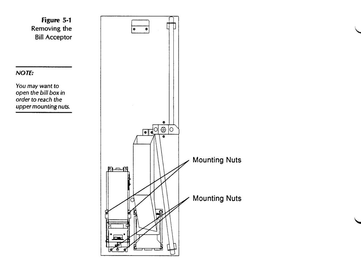
REMOVING THE BILL ACCEPTOR
Refer to Figure 5-1 as you remove the Bill Acceptor as follows:
- 1. Unplug the harness(es) from the Bill Acceptor. When certain bill acceptors are used, this step may need to be done after the unit is removed from the door.
- 2. Remove the 4 nuts holding the Bill Acceptor in place. Remove the Bill Acceptor.
INSTALLING THE BILL ACCEPTOR
Refer to Figure 5-1 as you install the Bill Acceptor as follows:
- 1. Plug the connector(s) into the Bill Acceptor.
- 2. Mount the Bill Acceptor to the door and tighten the 4 nuts used to hold it in place.
HOPPER
REMOVING THE HOPPER
If you are unfamiliar with the procedure to remove and replace the hopper, refer to Unloading the Hopper in Section 3 of this manual.
CLEANING THE HOPPER COIN PATH
NOTE:
Chain lubrication is not normally required.
The coin tracks inside the hopper are Teflon coated to minimize dirt build-up. It may still be necessary to clean them at regular intervals, as dictated by the number of vends and the environment, to prevent dirt accumulation in the coin path.
Failure to keep the coin path clean may result in coins sliding out of the track, causing the E r B message to occur even though the hopper contains a sufficient amount of coins.
Clean the hopper as follows:
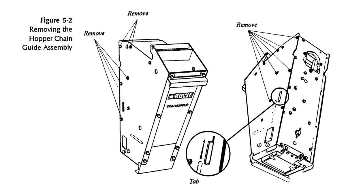
- 1. Remove the hopper from the bill changer and place it on a working surface.
- 2. Remove the black screws on each side of the hopper (Figure 5-2, 17 total), and lift the chain guide assembly up so that the tab (Figure 5-2, enlarged) can be pulled through the slot in the right hand side plate of the hopper assembly. When the tab is free, pull the chain guide assembly straight back out of the hopper.
NOTE:
Do not use detergents to clean the hopper. Detergent cleaners destroy the hopper's factory lubrication.
- 3. Using the Nylon hopper cleaning brush supplied with each machine, remove all dirt from the angular sides and flat surfaces of the serpentine coin path (Figure 5-3).
- 4. To reassemble the hopper, replace the chain guide assembly, securing the tab in its slot, and then start each of the screws removed in step 2. When all of the screws have been started, tighten all screws.
- 5. Replace the hopper in the bill changer. Be sure it is sitting securely in the pivot brackets, snug against the dispenser plate, and the catch is engaged.
- 6. Make a test vend to check for proper hopper operation.
Figure 5-3 Cleaning the Hopper Coin Path

Clean top and angular coin path surfaces, especially at guide edges, as shown
HOPPER CHAIN ADJUSTMENT
If the hopper coin path has been cleaned and the hopper still fails to operate correctly (jams or fails to pick up coins), you may need to adjust the hopper chain.
- 1. Remove the hopper from the bill changer and empty it of all coins (Section 3, Unloading the Hopper).
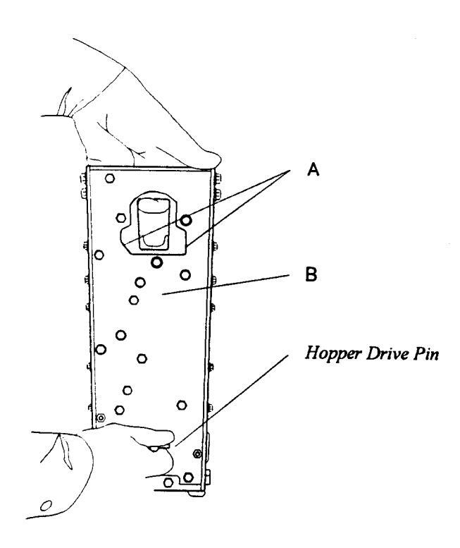
- 2. Loosen the three screws at the top back of the hopper (Figure 5-4, Ref. A and B) which allow the black plastic upper chain guide ring to move diagonally upward.
- 3. Pull the chain guide ring up with your index finger as shown in Figure 5-4. At the same time, rotate the hopper drive pin clockwise with your other hand until all slack is removed from the chain, but no binding is evident.
- 4. Tighten the two top screws (A), and then the bottom screw (B), that you loosened in step 2. If a torque wrench is available, adjust the chain so that the torque input at the drive shaft is one to four inch pounds.
Figure 5-4 Hopper Chain Adjustment
removed from the hopper before you adjust the chain
tension.
NOTE:
Make sure that all
coins have been
DISPENSER
REMOVING THE DISPENSER ASSEMBLY
- 1. Remove the hoppers from the Dispenser Assembly (Section 3, Unloading the Hopper).
- 2. Unplug the Dispenser harness from the P3 on the Control Computer.
- 3. Remove the two 1/4 20 screws on either side of the top of the Dispenser Plate.
- 4. Pivot the top of the Dispenser toward you, then slide the entire assembly to the right to release the left pivot pin from its bracket on the left side of the cabinet.
- 5. Pull the left side of the Dispenser toward you and move the assembly to the left to release the right pivot pin from its bracket on the left side of the cabinet.
Figure 5-5 Removing The Dispenser Assembly C-8/10

INSTALLING THE DISPENSER ASSEMBLY
- 1. Insert the right pivot pin into its bracket on the right side of the cabinet and slide the assembly fully to the right.
- 2. Swing the left pivot pin into alignment with its bracket, the slide the assembly to the left to fully engage the left pivot pin in its bracket.
- 3. Pivot the top of the assembly back into the machine and re-install the two 1/4-20 screws on either side of the top of the Dispenser Plate.
- 4. Plug the Dispenser Harness into P3 on the Control Computer.
- 5. Replace the hoppers, making sure that they are fully seated in their pivot brackets.
SECTION 6: TROUBLESHOOTING & SELF-DIAGNOSTICS
INTRODUCTION
The Century Series Bill Changers offer a number of self-diagnostic features that aid in troubleshooting. The microcomputer in the Changer Control Computer (CCC) monitors the changer functions, and displays an error code if it detects a malfunction. The meaning of each of the two-character error codes, and instructions for correcting each error, are discussed in this section.
This section also describes miscellaneous problems that can occur but may not cause an error code to be displayed, as well as checking procedures used to verify that the Bill Changer is functioning properly.
TROUBLESHOOTING
Logical troubleshooting minimizes the effort and expense of removing and replacing the wrong part. The Corrective Actions in this section are written in order from the most common to least probable solution, to help you put your Bill Changer back in service quickly, and with as little effort as possible.
Many failures are caused by minor problems such as loose connections or dirty contacts. Before replacing any parts, check to make sure that all plugs are firmly seated and that connector pins are not bent, broken, or pushed through the back of the connector when mated.
WARNING:
The Bill Changer operates on 120 or 220/240 VAC line voltage. If any possibility exists that the wall outlet may be wired backwards, or if the changer is connected to a wall outlet via a two-pronged grounding adapter, pull the plug from the outlet before attempting troubleshooting procedures. Failure to do so could result in serious electrical shock.
CLEARING BILL CHANGER ERROR CODES
After performing one of the Corrective Actions , reset the Bill Changer by pushing the UP and DOWN buttons simultaneously on the CCC while the NORMAL/PROGRAM switch is in the NORMAL position. If the error has been corrected, a dash will move from left to right across the 4-character status display.
If necessary, perform a test vend (or a number of them) with a valid bill to make sure that the error does not reappear.
ERROR CODES
The self diagnostic features of the Century Series Bill Changers are centered around the four-character status display on the CCC. The message displayed will tell you the type of fault encountered.
A description of each of the possible Bill Changer error codes follows. The Bill Acceptor may experience an error condition that is not communicated to the Changer Control. This is particularly true when pulse-type Bill Acceptors are used. There may be no indication that the Changer is disabled, but there will be no activity with the Bill Acceptor due to such an internal malfunction. In these cases, refer to the status indicator on the Bill Acceptor itself-and the Bill Acceptor Manual provided - in order to isolate and solve the problem.
ERROR CODES:
Er 1
Problem:
No coins or bills are accepted.
Symptom:
The changer is in shutdown due to an EEPROM error.
Corrective Action:
- 1. Enter the programming mode and check each program option.
- 2. Reprogram the machine if necessary.
- 3. Exit the programming mode. If the error returns, replace the CCC.
Er 2
Problem:
The changer did not payout coins for a bill accepted. A bill may have been stacked but no payout made.
Symptom:
The changer is in shutdown because the bill acceptor's output pulse was either too long or there were too many pulses issued. (Pulse type bill acceptors only.)
Corrective Action:
Pulse Type Bill Acceptor:
1. Verify that if a bill type is enabled at the bill acceptor, it is also enabled and that there is a proper payout setting for that bill in the CCC. If each is set properly and this error recurs, replace the CCC.
Serial Type Bill Acceptor:
- 1. If this was a new CCC being installed for the first time, enter the Programming Mode and program all setup options and the payout settings.
- 2. If the machine had been in operation, this code should never occur—replace the CCC.
Er 3
Problem:
The changer did not payout coins for a bill accepted. A bill may have been stacked but no payout made.
Symptom:
The changer is in shutdown because the bill acceptors' output pulse was either too long or there were too many pulses issued. (Pulse type bill acceptor only.)
Corrective Action:
Pulse Type Bill Acceptor:
If this is a newly installed Bill Acceptor -
Check the bill acceptor's pulse settings. All Credit Pulses must be between 19 and 120 MS in duration, with 19 to 150 MS space between pulses. One or two such pulses will be treated as a valid Type 1 Bill and if 3 to 7 are received, they will be treated as a valid Type 2 Bill. If there are 8 or more pulses detected, or the timing of the pulses or spaces are exceeds those mentioned, an ER 3 condition will result.
If this Bill Acceptor had been functioning in the Changer-
- 1. Check the wiring harness from the CCC to the Bill Acceptor for a short to ground.
- 2. Replace the Bill Acceptor.
Serial Type Bill Acceptor:
1. Make sure that the CCC is programmed for a serial type bill acceptor (682 or 683) and make the program change if necessary. If it is set for type 2, replace the CCC.
Er 4
Problem:
No coins or bills are accepted.
Symptom:
The changer is in shutdown because of a fault with the bill acceptor.
Corrective Action:
- 1. Check for a full bill acceptor stacker.
- 2. Check for any debris in the bill acceptor.
- 3. Replace the bill acceptor.
Note: If a Rowe CBA-4 or RBA-7 is used and the CCC is set for Bill Acceptor type 2, this error will disappear if the bill acceptor problem resolves itself. Under any other circumstances, however, this condition will remain in effect until the error is manually cleared.
Er 5 or Er 6 or Erll
Problem:
The changer did not payout the correct number of coins. ER 5 signifies that the left hopper was the source; ER 5 signifies that the right hopper caused the problem. E r i signifies that the machine failed to complete the payout and is operating in the MC Mode; i.e., neither hopper could satisfy the payout.
Symptom:
The changer is in shutdown because no coins were paid out of the hopper for 60 seconds after the dispenser was enabled or for 60 seconds after the previous coin during a dispense cycle.
Corrective Action:
- 1. Make sure the hopper is lifting the coins into the coin chute. Check for dirt build-up on the coin path (See Section 5). Check for coin jam or binding parts in the hopper.
- 2. Check the hopper motor. Remove the hopper and clear the error code. Perform a test vend on the changer using a valid bill or coin. If the motor runs, check carefully for excessive bind in the hopper (See Section 5). If the motor does not run, check for 120 VAC at the hopper motor. If voltage is present, the motor is defective. If there is no voltage present, proceed to Step 3.
- 3. Check for voltage at the CCC connection to the dispenser harness. If 120 VAC is present between P3 Pin 6 and P3 Pin 9, then the harness is at fault. Disconnect the 120 VAC, either at the wall plug or by disconnecting the harness at P4 on the CCC and then check for continuity between pin 6 and the hopper motor and pin 9 and the hopper motor. If continuity test fails, repair or replace the harness.
Note:
If a hopper motor feels very hot to the touch, wait until it cools down, then reset the CCC. Insert a bill to test for proper operation. If the motor operates after cooling off, check hopper for coin jams or binds.
Er 7
Problem:
The changer may have paid an extra coin from one or both of the hoppers.
Symptom:
The changer is in shutdown because two extra coins have been paid out, since the last time the changer was reset.
Corrective Action:
- 1. Check for mechanical problems with the dispenser assembly. Most likely the cause is mechanical, rather than electrical. Check the hopper motor brake's stop-pawl for wear or breakage. Check magnetic brake actuator for binds or sticking. Repair or replace hopper motor.
- 2. Check the wiring to the photo-detector cell and LED on the dispenser assembly for loose connections or pinched wiring. Repair wiring or replace photo-detector cell or LED.
Er B or Er 9
Problem:
The changer may have paid an incorrect number of coins. ER B signifies that the left hopper/ coin detector was the source; ER B signifies that the problem came from the right hopper/ coin detector.
Symptom:
The changer is in shutdown because the coin-detector is (or was) blocked.
Corrective Action:
- 1. Check for debris such as paper or a foreign object stuck between the photodetector and the LED on the dispenser assembly.
- 2. Verify that the LED is lit. Check the wiring to the photo-detector cell and LED on the dispenser assembly for loose connections or pinched wiring. Repair wiring or replace photo-detector cell or LED.
Erl D
Problem:
Programming Error.
Symptom:
The computer will not exit the programming mode because there is an error in the present setup.
Corrective Action:
1. A programmable setting is not correct for the conditions under which it was set. An example of this would be an additional bill type was enabled, but the payout settings for that bill type were not set. Verify all programming options and make any necessary changes. If the settings are correct, and the error persists, replace the CCC.
Fril - SEE PAGE L-5
Erl 2
Problem:
The changer is out of service.
Symptom:
The last customer was most likely short-changed due to loss of power during the payout cycle.
Corrective Action:
- 1. Make certain that there is a continuous power source connected to the Changer. Check to be certain that the supply is again restored properly. Check the fuse or circuit breaker is OK.
- 2. Check the internal circuit breaker (5A) and the ON-OFF switch for intermittent contact.
- 3. If the problem recurs, and power failure can be completely ruled out, replace the CCC.
- Er 13
This error should never occur in a Century Changer. If it does, replace the CCC.
Er 14
This error should never occur in a Century Changer. If it does, replace the CCC.
Erl5 or Erl6
Problem:
The changer does not contain enough coins to continue in service. Er 1 5 signifies that the left hopperis too low to continue; Er 1 5 signifies that the right hopper is too low to continue.
Symptom:
The changer is in shutdown because the low coin level sensor in the hopper has signalled a low level and the CCC has counted down to within 25 coins of the maximum payout.
Corrective Action:
- 1. Refill the hopper with the appropriate coins or tokens.
- 2. If the hopper contains sufficient coins, check the low level sensing circuit. The decimal point on the second-from-left 7-segment display is used as a low coin condition indicator for the hopper when lit.
If a low-level indicator is lit, but the hopper contains sufficient coins, the low coin level sensing circuit should be checked for proper operation.
3. Remove the hopper. The low-level indicator LED should not be lit. If it is lit, check the wiring between the low-level sensor contacts on the dispenser assembly and the CCC for pinched or shorted wiring. The voltage across pins 2 & 5 of P3 on the CCC should be 4.5 - 5.0 VDC. If this is the case, replace the hopper, or repair the low-level sensing circuits in the hopper.
Er21 or Er22 or Er23
Problem:
The changer goes out of service when trying to exit the programming mode.
Symptom:
The computer experienced a problem while saving information in its onboard memory chip.
Corrective Action:
1. The most likely cause for this would be a power loss during the programming process. Another possible cause could be a recurring low line voltage condition – See Erl 2.
- -
Problem:
The Changer will not accept coins.
Symptom:
The coin equipment is disabled because of a coin related error.
Corrective Action:
- 1. If a mechanical coin acceptor is installed, check the coin switch and switch actuator wire for proper operation. Check for a stuck coin or other object holding the switch closed. Clear the obstruction, and reset the error.
- 2. If an electronic coin acceptor is installed, check for a stuck coin or other object in the flight deck. Check the programming. Verify that if a coin type is enabled at the coin acceptor, it is enabled and the payout for that programmed into the CCC. If an electronic coin acceptor accepts a coin that was not programmed into the CCC, this error code will appear.
- 3. Check the wiring between the coin acceptor and the CCC for pinched or shorted wiring. If in doubt, disconnect the coin acceptor harness at the CCC. Reset the error. If the error does not return, replace the coin acceptor or the coin acceptor harness. If the error does return, replace the CCC.
MISCELLANEOUS PROBLEMS
The following problems may occur in the Bill Changer without causing a fault code.
ERRATIC PAYOUT
Problem:
The changer is not consistently dispensing the correct number of coins.
Symptom:
One vend is short a coin. The next vend contains an extra coin.
Corrective Action:
1. Check the coin chute on the back of the dispenser. Most likely, a coin is getting hung up in the dispenser coin chute, after it has been "counted" by the detector, then being shaken loose by a later vend. Check the coin chute for any dirt or obstruction that might cause a coin to hang up.
LARGE NUMBER OF VALID BILLS REJECTED
Problem:
The bill acceptor rejects a large number of valid bills.
Corrective Action:
Refer to the Troubleshooting Chart in the Bill Acceptor Field Service Manual and Parts Catalog included with your Bill Changer .
BILLS JAM FREQUENTLY
Problem:
Bills repeatedly become jammed in the Bill Acceptor transport.
Corrective Action:
Refer to the Bill Jamming Checklist in the Bill Acceptor Field Service Manual and Parts Catalog included with your Bill Changer .
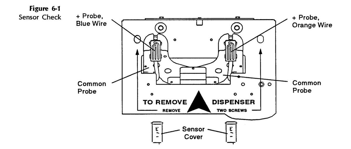
COIN COUNTING PHOTOTRANSISTOR (SENSOR) CHECK
Use the following procedure to check the phototransistor (sensor) in the dispenser coin detector system:
- 1. Switch the Bill Changer power OFF at the electrical box.
- 2. Remove the black plastic cover from the phototransistor and connect a common meter lead to the metal dispenser backing plate as shown in Figure 6-1.
- 3. Connect the positive (+) meter lead to the blue wire (Figure 6-1, Sensor Check Blue Wire).
- 4. Turn the power switch ON and check to see that the LED is lit. The meter should indicate between 4.7 and 5.2 VDC.
If the meter indication is not correct (between 4.7 and 5.2 VDC), the voltage regulator on the CCC board may need replacement (see Section 7) . Repair the malfunction before continuing this procedure.
If the meter reading is correct:
5. Move the + meter lead to the orange wire on the phototransistor as shown in Figure 6-1, Sensor Check - Orange Wire . The meter should indicate between 3.5 and 5.0 VDC.
If the voltage is less than 3.5 volts, replace the phototransistor board with the correct part number listed in Section 8: PARTS CATALOG .
LOW COIN SENSOR ELECTRICAL CHECK
Perform the following procedure to ensure that the Low Coin Sensor is functioning properly.
- 1. Turn the Bill Changer power to OFF.
- 2. Remove the hopper and empty it of all coins.
WARNING:
Make sure that the power is OFF before performing the following step.
- 3. Locate connector P3 on the Changer Control Computer (CCC). Connect a DC voltmeter to P3-5 (GND) and P3-4 (+).
- 4. Replace the empty hopper and turn Bill Changer power to ON. The voltmeter should read less than +.5 volts DC.
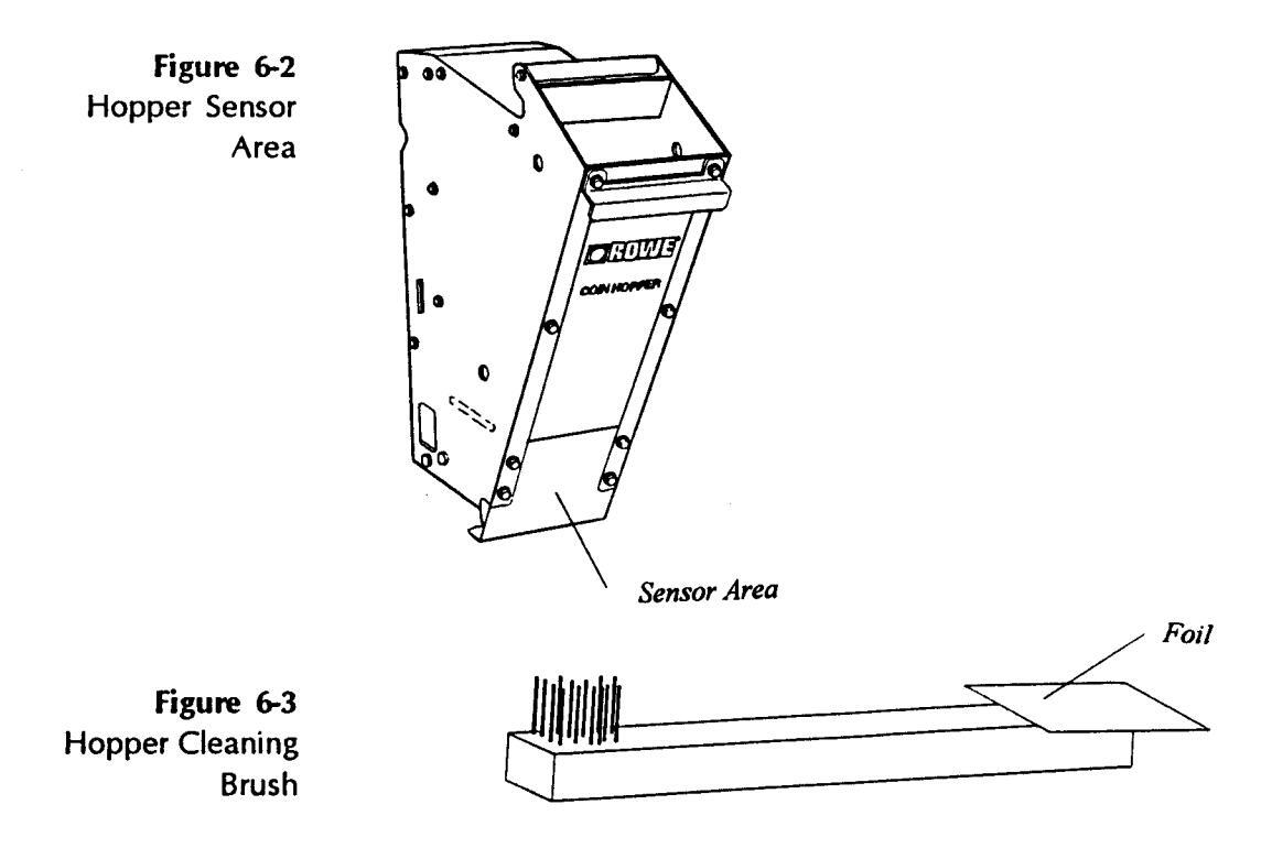
- 5. Tape 2 x 2 inch piece of aluminum foil around the end of a non-metallic object such as a long plastic ruler or wood stick. Figure 6-3, the Hopper Cleaning Brush is good for this purpose.
- 6. Place the foil end of the test object inside the hopper as close as possible to the location of the sensor ( Figure 6-2, Hopper Sensor Area ). The voltmeter should now have a reading of no less than 4.3 volts and a maximum of 5.5 volts.
SECTION 7: TECHNICAL INFORMATION
INTRODUCTION
The information contained in this section details the electronics found on the Changer Control Computer board, and is not intended for the casual repair person or the novice technician. No attempt should be made to repair the CCC board unless you have had considerable experience troubleshooting and repairing complex, microprocessor controlled electronic circuit boards.
Rowe® recommends that you send any failed CCC boards back to the factory for service.
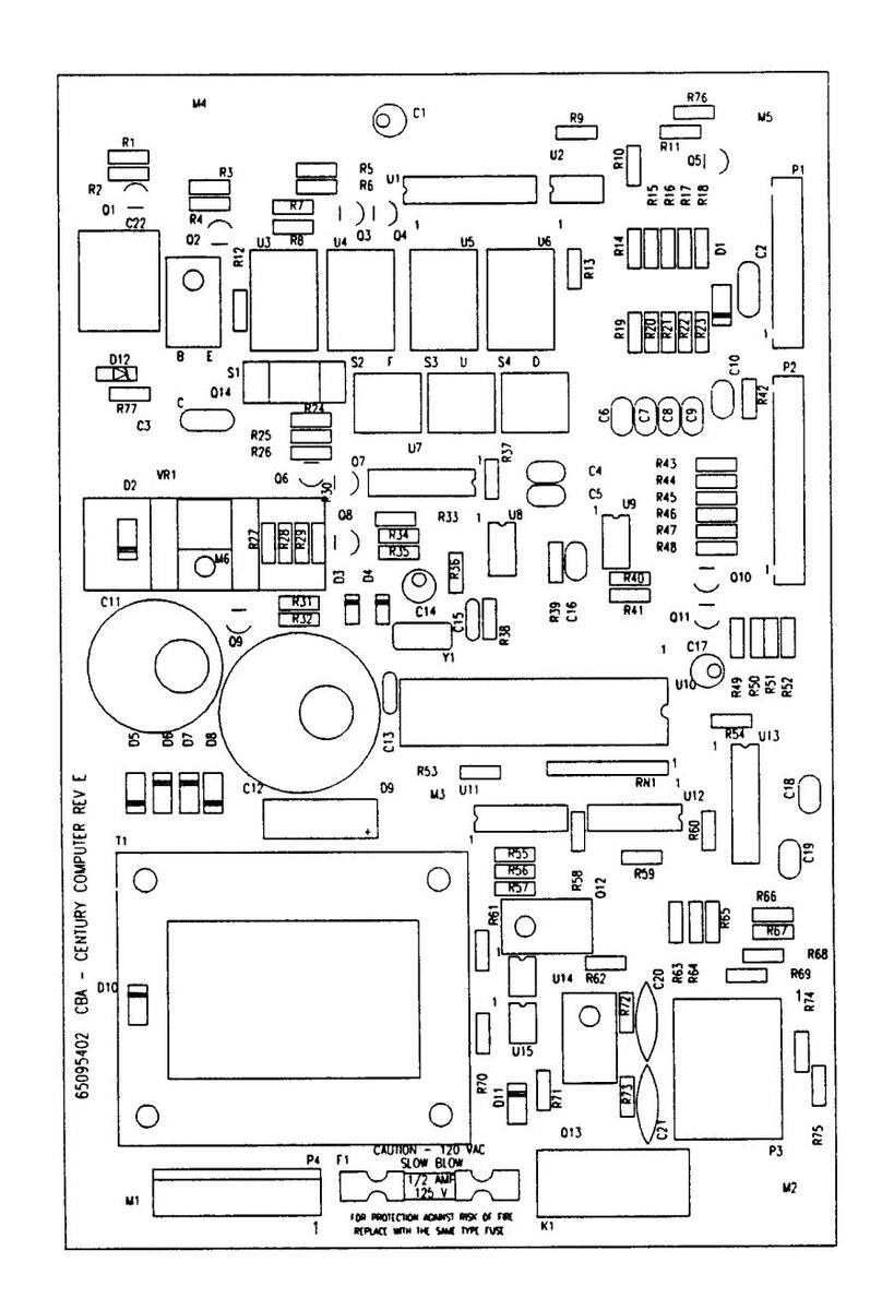
COMPONENTS LIST
CCC CIRCUIT BOARD 65095402 Rev. E
| C1 | CAPACITOR-ELECTROLYTIC 10V | /DC 2 | 20% | 100 UF | 70028128 |
|---|---|---|---|---|---|
| C2 | CAPACITOR-MONOLYTHIC CER | AMIC . | 20% | 1 UF | 70028521 |
| C3 | CAPACITOR-MONOLYTHIC CER/ | AMIC . | 20% | 1 UF | 70028521 |
| C4 | CAPACITOR-MONOLYTHIC CER/ | AMIC : | 20% | .1 UF | 70028514 |
| C5 | CAPACITOR-MONOLYTHIC CER/ | AMIC : | 20% | .1 UF | 70028514 |
| C6 | CAPACITOR-MONOLYTHIC CER/ | AMIC . | 20% | .1 UF | 70028514 |
| C7 | CAPACITOR-MONOLYTHIC CER/ | AMIC . | 20% | .1 UF | 70028514 |
| C8 | CAPACITOR-MONOLYTHIC CER/ | AMIC | 20% | .1 UF | 70028514 |
| C9 | CAPACITOR-MONOLYTHIC CER | AMIC | 20% | .1 UF | 70028514 |
| C10 | CAPACITOR-MONOLYTHIC CER/ | AMIC | 20% | .1 UF | 70028514 |
| C11 | CAPACITOR - ELECTROLYTIC 25 V | /DC | 20% | 4700 UF | 70023613 |
| C12 | CAPACITOR-ELECTROLYTIC 50 V | /DC | 20% | 2200 UF | 70023602 |
| C13 | CAPACITOR-MONOLYTHIC CER | AMIC | 20% | 22 PF | 70028705 |
| C14 | CAPACITOR-ELECTROLYTIC 10 | DC . | 20% | 100 UF | 70028128 |
| C15 | CAPACITOR-MONOLYTHIC CER | AMIC | 20% | 22 PF | 70028705 |
| C16 | CAPACITOR-MONOLYTHIC CER | AMIC | 20% | .1 UF | 70028514 |
| C17 | CAPACITOR-ELECTROLYTIC 10 | VDC | 20% | 100 UF | 70028128 |
| C18 | CAPACITOR-MONOLYTHIC CER | AMIC | 20% | .1 UF | 70028514 |
| C19 | CAPACITOR-MONOLYTHIC CER | AMIC | 20% | .1 UF | 70028514 |
| C20 | CAPACITOR - CERAMIC DISK 1 K | V | 20% | .01 UF | 70022508 |
| C21 | CAPACITOR - CERAMIC DISK 1 K | V | 20% | .01 UF | 70022508 |
| C22 | CAPACITOR-ELECTROLYTIC 16V | LOW ESR | 20% | 2200 UF | 70028311 |
| D1 | DIODE-SILICON | 1N4004 | 70035005 | ||
| D2 | DIODE-SILICON | 1N4004 | 70035005 | ||
| D3 | DIODE-SILICON | 1N4148 | 70035012 | ||
| D4 | DIODE-SILICON | 1N4148 | 70035012 | ||
| D5 | DIODE-SILICON | 1N4004 | 70035005 | ||
| D6 | DIODE-SILICON | 1N4004 | 70035005 | ||
| D7 | DIODE-SILICON | 1N4004 | 70035005 | ||
| D8 | DIODE-SILICON | 1N4004 | 70035005 | ||
| D9 | RECTIFIER-BRIDGE | 3 AMP | 21822503 | ||
| D10 | DIODE-SILICON | 1N4004 | 70035005 | ||
| D11 | DIODE-SILICON | 1N4004 | 70035005 | ||
| D12 | DIODE - ZENER 13V, 1W | 1N4743A | 70035506 | ||
| F1 | FUSE - SLOW BLOW 1/2 AMP 12 | 25V | 70072101 | ||
| K1 | RELAY PC BOARD (SPST) 12 VDC | 2 | 70042410 | ||
| P1 | HEADER - 2.5 MM 1 | 2 POS. | 70074312 | ||
| P2 | HEADER - 2.5 MM 1 | 5 POS. | 70074315 | ||
| P3 | HEADER - PC BOARD 1 | 2 POS. | 30763506 | ||
| P4 | HEADER - POLARIZED .156 | 8 POS. | 70075008 | ||
| Q1 | TRANSISTOR - SILICON PNP | MPSA56 | 70030104 | ||
| Q2 | TRANSISTOR - SILICON PNP | MPSA56 | 70030104 | ||
| Q3 | TRANSISTOR - SILICON PNP | MPSA56 | 70030104 | ||
| Q4 | TRANSISTOR - SILICON PNP | MPSA56 | 70030104 | ||
| Q5 | TRANSISTOR-SILICON DARLING | TON | TN6725A | 70030215 | |
| Q6 | TRANSISTOR - SILICON NPN | MPSA06 | 70030008 | ||
| Q7 | TRANSISTOR - SILICON NPN | MPSA06 | 70030008 | ||
| Q8 | TRANSISTOR - SILICON PNP | MPSA56 | 70030104 | ||
| Q9 | TRANSISTOR - SILICON NPN | MPSA06 | 70030008 |
|---|---|---|---|
| Q10 | TRANSISTOR - SILICON PNP | MPSA56 | 70030104 |
| Q11 | TRANSISTOR - SILICON PNP | MPSA56 | 70030104 |
| Q12 | THYRISTOR - TRIAC | T2500D | 70038102 |
| 013 | THYRISTOR - TRIAC | T2500D | 70038102 |
| Q14 | TRANSISTOR - DARLINGTON NPN | TIP102 | 70030808 |
| D1 | 10 4 | 70001107 | |
|
R1
R2 |
10 K | 79901103 | |
| D2 | PESISTOR CAPPON FILM 1/4W 5% | 10 K | 79901103 |
| RESISTOR CARBON FILM 1/4W 5% | 10 K | 79901103 | |
|
N4
DE |
RESISTOR - CARDON FILM 1/4W 5% | 79901103 | |
| RESISTOR - CARDON FILM 1/4W 5% | 10 K | 79901103 | |
| RESISTOR - CARBON FILM 1/4W 5% | 10 K | /9901103 | |
| K/ | RESISTOR - CARBON FILM 1/4W 5% | IUK | /9901103 |
| K8 | RESISTOR - CARBON FILM 1/4W 5% | 10 K | 79901103 |
| R9 | RESISTOR - CARBON FILM 1/4W 5% | 10 K | 79901103 |
| R10 | RESISTOR - CARBON FILM 1/4W 5% | 2.2 K | 79901222 |
| R11 | RESISTOR - CARBON FILM 1/4W 5% | 10 K | 79901103 |
| R12 | RESISTOR - CARBON FILM 1/4W 5% | 1 K | 79901102 |
| R13 | RESISTOR - CARBON FILM 1/4W 5% | 10 K | 79901103 |
| R14 | RESISTOR - CARBON FILM 1/4W 5% | 4.7 K | 79901472 |
| R15 | RESISTOR - CARBON FILM 1/4W 5% | 4.7 K | 79901472 |
| R16 | RESISTOR - CARBON FILM 1/4W 5% | 4.7 K | 79901472 |
| R17 | RESISTOR - CARBON FILM 1/4W 5% | 4.7 K | 79901472 |
| R18 | RESISTOR - CARBON FILM 1/4W 5% | 4.7 K | 79901472 |
| R19 | RESISTOR - CARBON FILM 1/4W 5% | 100 OHM | 79901101 |
| R20 | RESISTOR - CARBON FILM 1/4W 5% | 100 OHM | 79901101 |
| R21 | RESISTOR - CARBON FILM 1/4W 5% | 100 OHM | 79901101 |
| R22 | RESISTOR - CARBON FILM 1/4W 5% | 100 OHM | 79901101 |
| R23 | RESISTOR CARBON FILM 1/4W 5% | 100 OHM | 79901101 |
| R24 | RESISTOR - CARBON FILM 1/4W 5% | 47K | 79901472 |
| R25 | RESISTOR - CARBON FILM 1/4W 5% | 4.7 K | 79901472 |
| R25 | RESISTOR - CARBON FILM 1/4W 5% | 10 K | 70001472 |
|
R20
P17 |
10 K | 79901103 | |
|
N27
D00 |
79901103 | ||
|
K20
R20 |
79901102 | ||
| K29 | RESISTOR - CARBON FILM 1/4W 5% | 79901102 | |
| R30 | RESISTOR - CARBON FILM 1/4W 5% | IUK | 79901103 |
| R31 | RESISTOR - CARBON FILM 1/4W 5% | 4.7 K | 79901472 |
| R32 | RESISTOR - CARBON FILM 1/4W 5% | 4.7 K | 79901472 |
| R33 | RESISTOR - CARBON FILM 1/4W 5% | 1 K | 79901102 |
| R34 | RESISTOR - CARBON FILM 1/4W 5% | 1 K | 79901102 |
| R35 | RESISTOR - CARBON FILM 1/4W 5% | 1 K | 79901102 |
| R36 | RESISTOR - CARBON FILM 1/4W 2% | 5.6 K | 79902562 |
| R37 | RESISTOR - CARBON FILM 1/4W 5% | 10 K | 79901103 |
| R38 | RESISTOR - METAL FILM 1/4W 1% | 1 K | 799121001 |
| R39 | RESISTOR - CARBON FILM 1/4W 5% | 1 K | 79901102 |
| R40 | RESISTOR - CARBON FILM 1/4W 5% | 390 OHM | 79901391 |
| R41 | RESISTOR - CARBON FILM 1/4W 5% | 1 K | 79901102 |
| R42 | RESISTOR - CARBON FILM 1/4W 5% | 1 K | 79901102 |
| R43 | RESISTOR - CARBON FILM 1/4W 5% | 220 OHM | 79901221 |
| R44 | RESISTOR - CARBON FILM 1/4W 5% | 220 OHM | 79901221 |
| R45 | RESISTOR - CARBON FILM 1/4W 5% | 1 K | 79901102 |
| R46 | RESISTOR - CARBON FILM 1/4W 5% | 1 K | 79901102 |
| R47 | RESISTOR - CARBON FILM 1/4W 5% | 10 K | 79901103 |
| R48 | RESISTOR - CARBON FILM 1/4W 5% | 10 K | 79901103 |
| RAQ | RESISTOR - CARBON FILMA 1/4/N/ 5% | 680444 | 79901689 |
| ハサブ | 0.0 01 101 | 7 7701009 |
25554501
| ( |
|---|
| ٠ |
| ٠ |
| 1 |
| R50 | RESISTOR - CARBON FILM 1/4W 5% | 10 K | 79901103 |
|---|---|---|---|
| R51 | RESISTOR - CARBON FILM 1/4W 5% | 1 K | 79901102 |
| R52 | RESISTOR - CARBON FILM 1/4W 5% | 10 K | 79901103 |
| R53 | RESISTOR - CARBON FILM 1/4W 5% | 10 K | 79901103 |
| R54 | RESISTOR - CARBON FILM 1/4W 5% | 1 K | 79901102 |
| R55 | RESISTOR - CARBON FILM 1/4W 5% | 10 K | 79901103 |
| R56 | RESISTOR - CARBON FILM 1/4W 5% | 10 K | 79901103 |
| R57 | RESISTOR - CARBON FILM 1/4W 5% | 10 K | 79901103 |
| R58 | RESISTOR - CARBON FILM 1/4W 5% | 1 K | 79901102 |
| R59 | RESISTOR - CARBON FILM 1/4W 5% | 10 K | 79901103 |
| R60 | RESISTOR - CARBON FILM 1/4W 5% | 10 K | 79901103 |
| R61 | RESISTOR - CARBON FILM 1/4W 5% | 150 OHM | 79901151 |
| R62 | RESISTOR - CARBON FILM 1/4W 5% | 150 OHM | 79901151 |
| R63 | RESISTOR - CARBON FILM 1/4W 5% | 1 K | 79901102 |
| R64 | RESISTOR - CARBON FILM 1/4W 5% | 4.7 K | 79901472 |
| R65 | RESISTOR - CARBON FILM 1/4W 5% | 4.7 K | 79901472 |
| R66 | RESISTOR - CARBON FILM 1/4W 5% | 1 K | 79901102 |
| R67 | RESISTOR - CARBON FILM 1/4W 5% | 1 K | 79901102 |
| R68 | RESISTOR - CARBON FILM 1/4W 5% | 100 OHM | 79901101 |
| R69 | RESISTOR - CARBON FILM 1/4W 5% | 100 OHM | 79901101 |
| R70 | RESISTOR - CARBON FILM 1/4W 5% | 150 OHM | 79901151 |
| R71 | RESISTOR - CARBON FILM 1/4W 5% | 1.5 K | 79901152 |
| R72 | RESISTOR - CARBON FILM 1/4W 5% | 1.5 K | 79901152 |
| R73 | RESISTOR - CARBON FILM 1/4W 5% | 150 OHM | 79901151 |
| R73 | RESISTOR - CARBON FILM 1/4W 5% | 47 OHM | 79901470 |
| R75 | RESISTOR - CARBON FILM 1/4W 5% | 47 OHM | 79901470 |
|
R7 J
P76 |
1.8 OHM | 79901189 | |
|
R70
D77 |
150 OHM | 79904151 | |
| RN1 | RESISTOR NETWORK SIP 5% SIP9 | 10K X 8 | 799091030901 |
| C1 | 70045001 | ||
| 51 | 21773303 | ||
| 52 | 21773303 | ||
| 53 | SWITCH PUSHBUITON | 21//3303 | |
| 54 | SWITCH PUSHBUTTON | 21775505 | |
| Т1 | TRANSFORMER - PC MOUNT | 45084403 | |
| U1 | IC - LED DISPLAY DRIVER | MM5481 | 30800264 |
| U2 | IC - EPROM 128 X 16 SERIAL | 93C56 | 30800263 |
| U3 | LED DISPLAY 7 SEGMENT COMMON ANODE | 21766708 | |
| U4 | LED DISPLAY 7 SEGMENT COMMON ANODE | 21766708 | |
| U5 | LED DISPLAY 7 SEGMENT COMMON ANODE | 21766708 | |
| U6 | |||
| LED DISPLAY 7 SEGMENT COMMON ANODE | 21766708 | ||
| U7 |
LED DISPLAY 7 SEGMENT COMMON ANODE
IC - 1 OF 8 MULTIPLEXER |
74HCT151 |
21766708
79930151 |
|
U7
U8 |
LED DISPLAY 7 SEGMENT COMMON ANODE
IC - 1 OF 8 MULTIPLEXER IC - UP SUPERVISOR |
74HCT151
MAX813L |
21766708
79930151 30800296 |
|
U7
U8 U9 |
LED DISPLAY 7 SEGMENT COMMON ANODE
IC - 1 OF 8 MULTIPLEXER IC - UP SUPERVISOR IC - DUAL OP AMP |
74HCT151
MAX813L LM358 |
21766708
79930151 30800296 30800214 |
|
U7
U8 U9 U10 |
LED DISPLAY 7 SEGMENT COMMON ANODE
IC - 1 OF 8 MULTIPLEXER IC - UP SUPERVISOR IC - DUAL OP AMP MICROCOMPUTER |
74HCT151
MAX813L LM358 87C52 |
21766708
79930151 30800296 30800214 70039411 |
|
U7
U8 U9 U10 U11 |
LED DISPLAY 7 SEGMENT COMMON ANODE
IC - 1 OF 8 MULTIPLEXER IC - UP SUPERVISOR IC - DUAL OP AMP MICROCOMPUTER IC - HEX INVERTER OPEN COLLECTOR |
74HCT151
MAX813L LM358 87C52 74LS05 |
21766708
79930151 30800296 30800214 70039411 70037108 |
|
U7
U8 U9 U10 U11 U12 |
LED DISPLAY 7 SEGMENT COMMON ANODE
IC - 1 OF 8 MULTIPLEXER IC - UP SUPERVISOR IC - DUAL OP AMP MICROCOMPUTER IC - HEX INVERTER OPEN COLLECTOR IC - HEX INVERTER OPEN COLLECTOR |
74HCT151
MAX813L LM358 87C52 74LS05 74LS05 |
21766708
79930151 30800296 30800214 70039411 70037108 70037108 |
|
U7
U8 U9 U10 U11 U12 U13 |
LED DISPLAY 7 SEGMENT COMMON ANODE
IC - 1 OF 8 MULTIPLEXER IC - UP SUPERVISOR IC - DUAL OP AMP MICROCOMPUTER IC - HEX INVERTER OPEN COLLECTOR IC - HEX INVERTER OPEN COLLECTOR IC - DRIVER OCTAL SINK |
74HCT151
MAX813L LM358 87C52 74LS05 74LS05 ULN2595A |
21766708
79930151 30800296 30800214 70039411 70037108 70037108 70036913 |
|
U7
U8 U9 U10 U11 U12 U13 U14 |
LED DISPLAY 7 SEGMENT COMMON ANODE
IC - 1 OF 8 MULTIPLEXER IC - UP SUPERVISOR IC - DUAL OP AMP MICROCOMPUTER IC - HEX INVERTER OPEN COLLECTOR IC - HEX INVERTER OPEN COLLECTOR IC - DRIVER OCTAL SINK IC - OPTOCOUPLER OPTO - TRIAC |
74HCT151
MAX813L LM358 87C52 74LS05 74LS05 ULN2595A IS-3021 |
21766708
79930151 30800296 30800214 70039411 70037108 70037108 70036913 70033705 |
|
U7
U8 U9 U10 U11 U12 U13 U14 U15 |
LED DISPLAY 7 SEGMENT COMMON ANODE
IC - 1 OF 8 MULTIPLEXER IC - UP SUPERVISOR IC - DUAL OP AMP MICROCOMPUTER IC - HEX INVERTER OPEN COLLECTOR IC - HEX INVERTER OPEN COLLECTOR IC - DRIVER OCTAL SINK IC - OPTOCOUPLER OPTO - TRIAC IC - OPTOCOUPLER OPTO - TRIAC |
74HCT151
MAX813L LM358 87C52 74LS05 74LS05 ULN2595A IS-3021 IS-3021 |
21766708
79930151 30800296 30800214 70039411 70037108 70037108 70033705 70033705 |
|
U7
U8 U9 U10 U11 U12 U13 U14 U15 UX1 |
LED DISPLAY 7 SEGMENT COMMON ANODE
IC - 1 OF 8 MULTIPLEXER IC - UP SUPERVISOR IC - DUAL OP AMP MICROCOMPUTER IC - HEX INVERTER OPEN COLLECTOR IC - HEX INVERTER OPEN COLLECTOR IC - DRIVER OCTAL SINK IC - OPTOCOUPLER OPTO - TRIAC IC - OPTOCOUPLER OPTO - TRIAC IC - OPTOCOUPLER OPTO - TRIAC SOCKET - IC DIP - 40 (U-10) |
74HCT151
MAX813L LM358 87C52 74LS05 74LS05 ULN2595A IS-3021 IS-3021 |
21766708
79930151 30800296 30800214 70039411 70037108 70036913 70033705 70033705 70033705 |
|
U7
U8 U9 U10 U11 U12 U13 U14 U15 UX1 VR1 |
LED DISPLAY 7 SEGMENT COMMON ANODE
IC - 1 OF 8 MULTIPLEXER IC - UP SUPERVISOR IC - DUAL OP AMP MICROCOMPUTER IC - HEX INVERTER OPEN COLLECTOR IC - HEX INVERTER OPEN COLLECTOR IC - DRIVER OCTAL SINK IC - OPTOCOUPLER OPTO - TRIAC IC - OPTOCOUPLER OPTO - TRIAC IC - OPTOCOUPLER OPTO - TRIAC SOCKET - IC DIP - 40 (U-10) VOLTAGE REGULATOR - LOW DROPOUT |
74HCT151
MAX813L LM358 87C52 74LS05 74LS05 ULN2595A IS-3021 IS-3021 LM330T-5.0 |
21766708
79930151 30800296 30800214 70039411 70037108 70037108 70036913 70033705 70033705 70074240 70036528 |
|
U7
U8 U9 U10 U11 U12 U13 U14 U15 UX1 VR1 Y1 |
LED DISPLAY 7 SEGMENT COMMON ANODE
IC - 1 OF 8 MULTIPLEXER IC - UP SUPERVISOR IC - DUAL OP AMP MICROCOMPUTER IC - HEX INVERTER OPEN COLLECTOR IC - HEX INVERTER OPEN COLLECTOR IC - DRIVER OCTAL SINK IC - OPTOCOUPLER OPTO - TRIAC IC - OPTOCOUPLER OPTO - TRIAC IC - OPTOCOUPLER OPTO - TRIAC SOCKET - IC DIP - 40 (U-10) VOLTAGE REGULATOR - LOW DROPOUT CRYSTAL - QUARTZ 9.216 MHZ |
74HCT151
MAX813L LM358 87C52 74LS05 74LS05 ULN2595A IS-3021 IS-3021 LM330T-5.0 |
21766708
79930151 30800296 30800214 70039411 70037108 70037108 70033705 70033705 70034240 70036528 25167323 |
SECTION 8: PARTS CATALOG
| Catalog Description | |
|---|---|
| Parts I ist Description | |
| Ordering Replacement Parts | |
| Ordering replacement r ur w initiation |
PARTS CATALOG
IN
| C-8, C-10 Door Assembly | |
|---|---|
| C-8, C-10 Cabinet Assembly | |
| C-8 Hopper Assembly | |
| C-10 Hi Capacity Hopper Assembly | |
| C-8, C-10 Coin Acceptor Assembly | |
| C-8, C-10 Coin Dispenser Assembly | |
| C-8, C-10 Change Bucket Assembly | |
| Electrical Box Assembly | |
| Accessory Kits | 8-21 |
| • |
This page intentionally left blank.
INTRODUCTION
This parts catalog lists procurable replacement parts for the Century Series Bill Changer. The purpose of this parts catalog is to help you locate and identify replaceable components and supply information on how to order them.
Catalog Description
This catalog is divided into sections ( figures ), which include a parts list and corresponding illustration. Some assemblies require more than one illustration to identify its parts. In this case, each included page has a sheet number to identify it as part of one assembly.
Since replacing parts that are welded or riveted onto an assembly is normally impractical, replacement parts are not listed for these items. The assembly that contains the welded part should be replaced.
Parts List Description
The parts list contains four columns:
- Reference Number The reference number is used to identify a part on the illustration. The abbreviation "Ref" is used in place of a number when items are listed for reference purposes only, or when the item listed is an alternate part.
- Rowe Part Number This column lists the part number to use when ordering replacement parts or making inquiries.
- Description This column gives a description of each part or assembly. Items are indented with a "bullet" (•) to show their relationship to the next higher assembly.
- Qty This column contains the part quantity used in the assembly. When a figure describes more than one model of an assembly, the "Qty" column is divided to show each model.
Ordering Replacement Parts
All replacement parts must be ordered directly from an Authorized Rowe® Distributor.
A Standard Parts Order Form is available from your Rowe® Distributor at no charge. Parts orders are often delayed because of inadequate information on parts order forms. To enable prompt delivery, always specify the following information:
- Part Number and Description (indicate color, if applicable)
- · Quantity Required
- Machine Model and Serial Number
- Complete Shipping Address, including the ZIP code
- Shipping Instructions (Must be included). If the shipping method is Parcel Post, Air Parcel Post, United Parcel Service, or Air UPS, and the packages may exceed the size and weight limits of these services, indicate an alternate shipping method.
If the shipment must be delivered as fast as possible, specify "Fastest Way". Rowe® will select the carrier for orders that justify shipment by truck.

| Def | Dava N.a | Description | •••• |
|---|---|---|---|
| kei. | ran no. | Description Qi | ĩ۷ |
| *** | |||
| 1 | 65421002 | C-8 Door Weld Assembly | 1 |
| 65421001 | C-10 Door Weld Assembly | 1 | |
| 2 | 47901420 | T-Handle Assembly - Pop Out (Without Lock Cylinder and Key) | . 1 |
| 3 | 25251801 | Light - Indicator (Temporarily Out of Service) | . 1 |
| 4 | 35116901 | Change Cup Door | . 1 |
| 5 | 65431401 | Label - Door (C-8 Domestic With Coin Acceptor) | 1 |
| 65431402 | Label - Door (C-8 Domestic - No Coin Acceptor) | . 1 | |
| 65431101 | Label - Door (C-10 Domestic With Coin Acceptor) | . 1 | |
| 65431103 | Label - Door (C-10 Domestic - No Coin Acceptor) | .1 | |
| 6 | 35143601 | Trim Plate (With Coin Acceptor) | 1 |
| 35143602 | Trim Plate (No Coin Acceptor) | . 1 | |
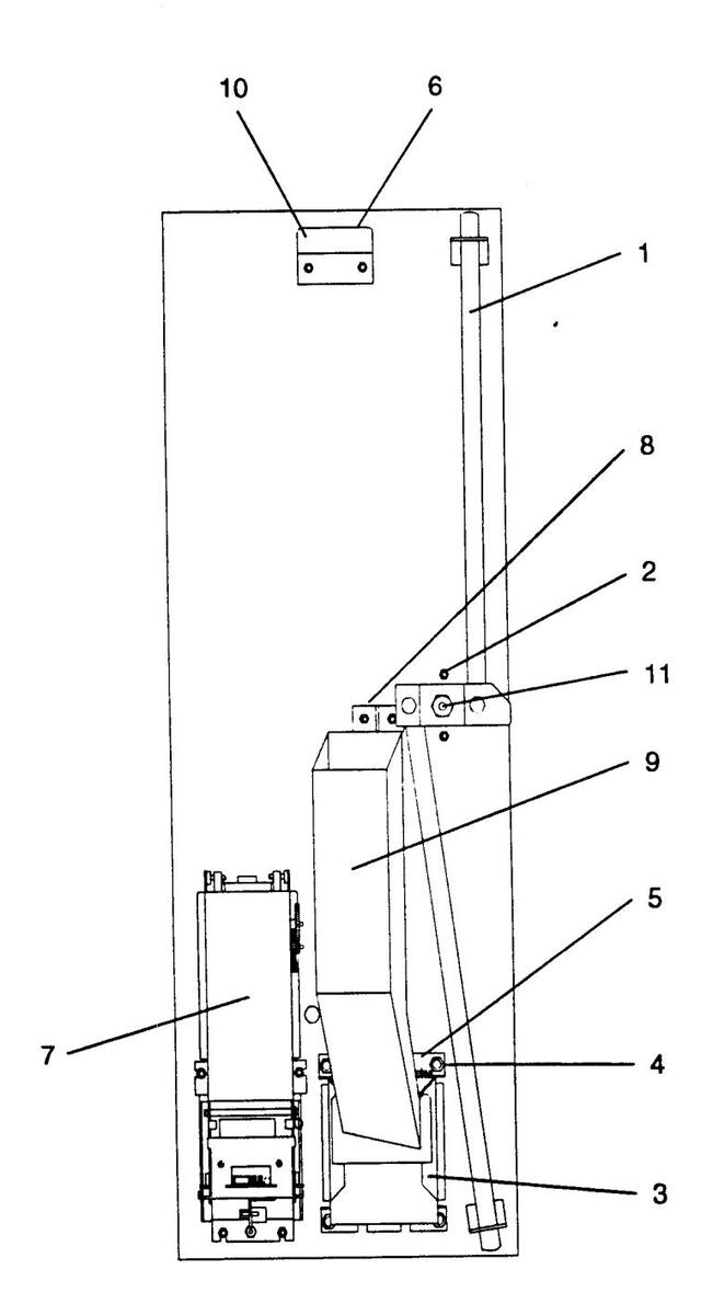
8-6
| ********** | 88 | |||
|---|---|---|---|---|
| 1 | Ref. | Part No. | Description Q | ty |
|
885
1 |
||||
| 1 | 35131405 | C-8 Lockbar Assembly | 1 | |
| 35131406 | C-10 Lockbar Assembly | 1 | ||
| 2 | 70134103 | #10-24 Carriage Bolt | 2 | |
| 3 | 45085601 | Coin Cup Assembly | 1 | |
| . 4 | 35121501 | Coin Cup Mounting Bracket | 2 | |
| 5 | 25239701 | Coin Cup Door Shaft | . 1 | |
| 25181701 | Tension Spring | . 1 | ||
| 6 | 25190003 | Foam Pad | . 1 | |
| 7 | 65073229 | CBA-4 - $1, $5, $10, $20 | . 1 | |
| 8 | 45109401 | Coin Mech Bracket & Chute Assembly | . 1 | |
| 9 | 45109501 | Coin Chute Assembly | . 1 | |
| 10 | 25211503 | Bracket | . 1 | |
| 11 | 92400181 | #1/2-20 UNC Self Locking Nut | . 2 | |
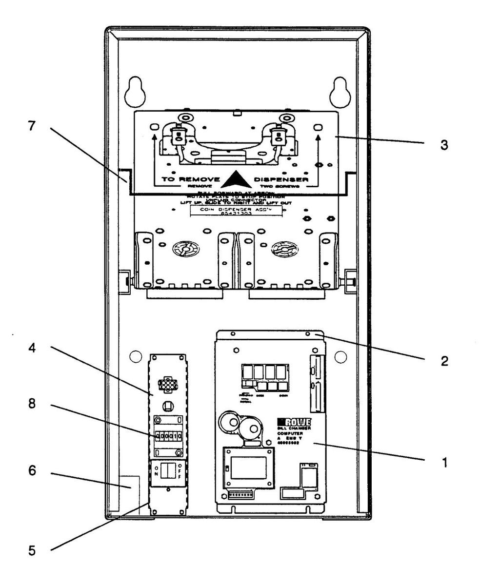
| Ref. | Part No. | Description | Qty |
|---|---|---|---|
| 1 | 45085902 | Computer Assembly | 1 |
| 45085205 | Cover - Computer | I | |
| 65095402 | Circuit Board Assembly - Computer | 1 | |
| (See Section 7 for Circuit Board Layout & Components) | |||
| 2 | 25249102 | Insulation - Base | 1 |
| 3 | 65431302 | Coin Dispenser Assembly (Low Coin) C-8 (See Figure 8-7) | 1 |
| 65431301 | Coin Dispenser Assembly (Low Coin) C-10 (See Figure 8-7) | 1 | |
| 4 | 45085303 | Electrical Box Assembly (See Figure 8-9) | 1 |
| 5 | 35132801 | Electrical Box Plate | 2 |
| 6 | 45108902 | Coin Box (Coin Acceptor Only) | 1 |
| 7 | 35144601 | Bail Wire | 1 |
| 8 | 25065710 | Counter Assembly | 1 |
| Parts Not S | hown: | ||
| 65094907 | Standard Capacity Hopper Assembly (Small Coins) (C-8 Only) (See Figure 8-4) | 1 | |
| 65094908 | Standard Capacity Hopper Assembly (Large Coins) (C-8 Only) (See Figure 8-4) | 1 | |
| 65092903 | Hi Capacity Hopper Assembly (Small Coins) (C-10 Only) (See Figure 8-5) | 1 | |
| 65092904 | Hi Capacity Hopper Assembly (Large Coins) (C-10 Only) (See Figure 8-5) | 1 | |
| 35131301 | Power Cord Assembly | 1 | |
| 70232302 | Strain Relief - Right Angle | 1 | |
| 45108102 | Harness Assembly - Dispenser | 1 | |
| 45109102 | Harness Assembly - Power | 1 | |
| 45108201 | Harness Assembly - Computer to CBA4 B.A. | 1 | |
| 45108203 | Harness Assembly - Computer to MARS/COINCO B.A. | 1 | |
| 45108204 | Harness Assembly - Power (MARS/COINCO B.A.) | 1 | |
| 45108205 | Harness Assembly - Computer to Cashcode B.A. | 1 | |
| 45108208 | Harness Assembly - Computer to RBA - 7BA | 1 |

| Ref. | Part No. | Description | Qt |
|---|---|---|---|
| 65094907 | Hopper Assembly (Small Coins) | Re | |
| 65094908 | Hopper Assembly (Large Coins) | Re | |
| 1 | 45032401 | L.H. Side Assembly | |
| 2 | 25098101 | Hopper Handle | |
| 3 | 35044640 | Front Cover (Small Coins) | |
| 35044641 | Front Cover (Large Coins) | •••• | |
| 4 | 45032501 | R.H. Side Assembly | •••• |
| 5 | 65028202 | Sliding Funnel | |
| 6 | 65027903 | Fixed Funnel | •••• |
| 7 | 25113701 | Drive Shaft And Pin Assembly (Small Coins) | |
| 25113702 | Drive Shaft And Pin Assembly (Large Coins) | •••• | |
| 8 | 70120903 | Washer | •••• |
| 9 | 70121624 | Spacer | •••• |
| 10 | 35048801 | Tie Bracket | •••• |
| 11 | 35047201 | Agitator Cam (Small Coins) | •••• |
| 35047202 | Agitator Cam (Large Coins) | •••• | |
| 12 | 45032101 | Coin Baffle (Small Coins) | |
| 45032102 | Coin Baffler (Large Coins) | ||
| 13 | 70146006 | Nyliner Bearing | |
| 14 | 35048501 | Chain Guide | •••• |
| 15 | 35060501 | Plate and Post Assembly | •••• |
| 16 | 70146021 | Nyliner Bearing | |
| 17 | 35043703 | Extended Pin Chain (Small Coins) | •••• |
| 35043705 | Extended Pin Chain (Large Coins) | ||
| 18 | 70134109 | Special Screw (Black) | |
| 19 | 25113401 | Compression Spring | |
| 20 | 45034205 | Coin Agitator (Small Coins) | •••• |
| 45034204 | Coin Agitator (Large Coins) | •••• | |
| 21 | 35044502 | Inner Coin Guide Assembly (Small Coins) | |
| 35044504 | Inner Coin Guide Assembly (Large Coins) | •••• | |
| 22 | 65028803 | Chain Guide Ring | |
| 23 | 45031902 | Outer Coin Slide Assembly (Small Coins) | |
| 45031903 | Outer Coin Slide Assembly (Large Coins) | ||
| 24 | 45035601 | Sprocket | |
| 25 | 35047101 | Drive Spacer | |
| 26 | 25165902 | Hopper Handle | |
| 27 | 25226901 | Coin Ramp (Large Coins) | |
| This assemb | ly, including items 21 and 23, is available as a replacement part as follows: | ||
| 28 | 47000601 | Coin and Chain Guide Assembly (Small Coins) | |
| 47000602 | Coin and Chain Guide Assembly (Large Coins) | ||
| 29 | 45106901 | CBA Low Coin Sensor | |
| 30 | 35142901 | Bracket - Contact Mounting | |
| 31 | 25553001 | Flattener - Antenna | •••• |
| 32 | 70220804 | Tape - Foamed | |
| 33 | 45107301 | Bracket - Antenna Cover | |
| 34 | 35173901 | Cover - Circuit Board | •••• |
| 35 | 21776009 | Fastener - Speed Clin | •••• |
| 36 | 25552301 | Spacer - Contact Board | •••• |
| 37 | 92803607 | Gasket - Poly | •••• |
| 38 | 45131501 | •••• |
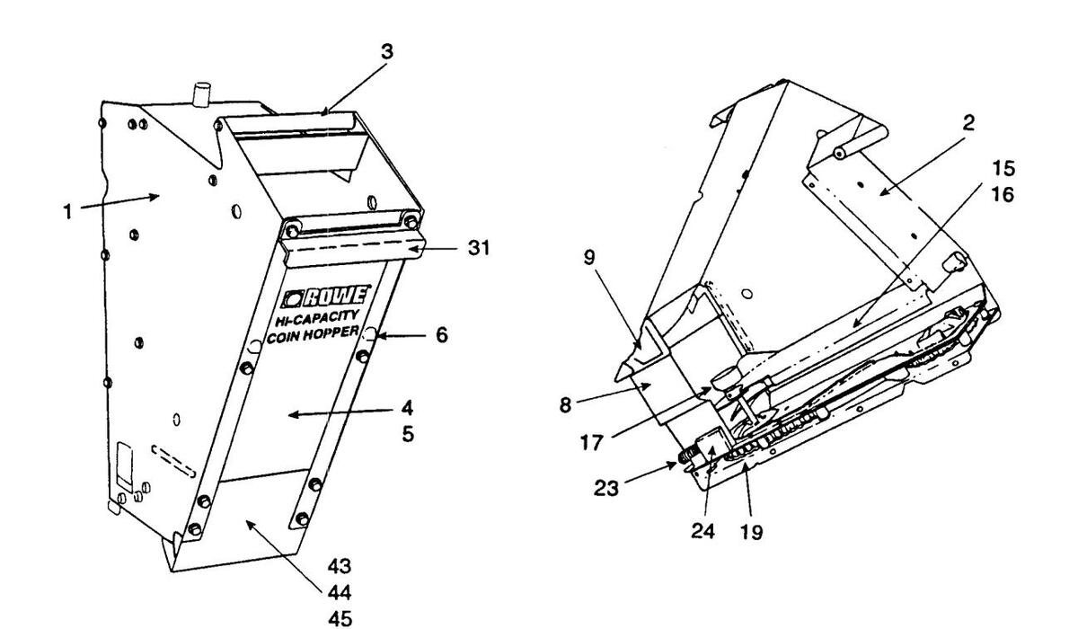
27
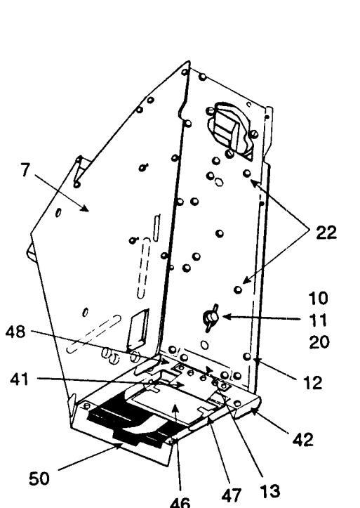

Figure 8-5. C-10 Hi Capacity Hopper Assembly
| Ref. | Part No. | Description | Q |
|---|---|---|---|
| 65092903 | Hi-Capacity Hopper Assembly (Small Coins) | ||
| 65092904 | Hi-Capacity Hopper Assembly (Jarge Coins) | Re | |
| 1 | 45032402 | L.H. Side Assembly | |
| 2 | 35074201 | Top Assembly | |
| 3 | 25098101 | Hopper Handle | ••••• |
| 4 | 35044638 | Front Cover (Small Coins) | |
| 5 | 35044639 | Front Cover (large Coins) | |
| 6 | 25114701 | Bumper | |
| 7 | 45032503 | R.H. Side Assembly | •••• |
| 8 | 65027902 | ••••• | |
| 9 | 65027903 | Fixed Funnel | ••••• |
| 10 | 25113701 | Drive Shaft And Pin Assembly (Small Coins) | •••• |
| 11 | 70120903 | Washer | ••••• |
| 12 | 70121624 | Spacer | •••• |
| 13 | 35048801 | Tie Bracket | |
| 14 | 35058101 | Agitator Cam (Small Coins) | •••• |
| 15 | 45072101 | Coin Baffle And Stud Assembly (Small Coins) | •••• |
| . 🛥 | 25224501 | Baffle And Bracket Assembly | •••• |
| 16 | 45072102 | Coin Baffle And Stud Assembly (Large Coins) | •••• |
| 25224501 | Raffle And Bracket Assembly | •••• | |
| 17 | 70146006 | Nyliner Rearing | •••• |
| 18 | 35048501 | Chain Guide | •••• |
| 19 | 35060501 | Plate and Post Assembly | •••• |
| 20 | 70146021 | Nyliner Bearing | •••• |
| 21 | 35043703 | Extended Pin Chain (Small Coins) | •••• |
| 22 | 70134109 | Special Screw (Black) | •••• |
| 23 | 25113401 | Compression Spring | •••• |
| 24 | 65028202 | Sliding Funnel | •••• |
|
2
75 |
45034205 | Agitator (Small Coinc) | •••• |
| 26 | 350/4200 | Inner Coin Guide Assembly (Small Coins) | •••• |
| 27 | 65028802 | Chain Guide Ring | •••• |
|
≁/
28 |
45020003 | Outer Coin Slide Assembly (Small Coins) | •••• |
|
20
20 |
45035601 | Sprocket | •••• |
|
20
20 |
350/7101 | ••• | |
| 21 | 25165002 | Honner Handle | ••• |
| 20 | 45024204 | Agitator (Lorgo Color) | ••• |
|
37
22 |
40004204 | Agitator Com (Large Collis) | ••• |
| 27 | 3303010Z | Agnator Carri (Large Coms) | ••• |
| 25 | 20110/02 | Evtended Din Chain (Large Coins) | ••• |
| 22 | 25042702 | Extended Fill Clain (Large Collis) | ••• |
|
30
27 |
35044504 | Inner Coin Guide (Large Coins) | •••• |
|
ע
סכ |
20171202 | Opper Agnator Assembly (Large Coins) | ••• |
| 30 | /0113013 | Koll Fin (Large Coins) | ••• |
|
37
40 |
45031903 | Outer Coin Slide Assembly (Large Coins) | ••• |
| 40 | 25226901 | Coin Kamp (Large Coins) | ••• |
| 41 | 45106902 | CBA Low Coin Sensor (Hi Capacity Hopper) | ••• |
| 42 | 35142901 | Bracket - Contact Mounting | •••• |
| 43 | 25553001 | riattener - Antenna | •••• |
| 44 | /0220804 | Tape - Foamed | •••• |
| 45 | 4510/302 | Bracket - Antenna Cover | ••• |
| 46 | 35173901 | Cover - Circuit Board | •••• |
| 47 | 21776009 | Fastener - Speed Clip | •••• |
| 48 | 25552301 | Spacer - Contact Board | •••• |
| This assembly, | including items 26, 28, 36 and 39, is available as a replacement part as follows: | ||
| 49 | 47000601 | Coin and Chain Guide Assembly (Small Coins) | •••• |
| 47000602 | Coin and Chain Guide Assembly (Large Coins) | •••• | |
| 50 | 92803607 | Gasket - Poly |
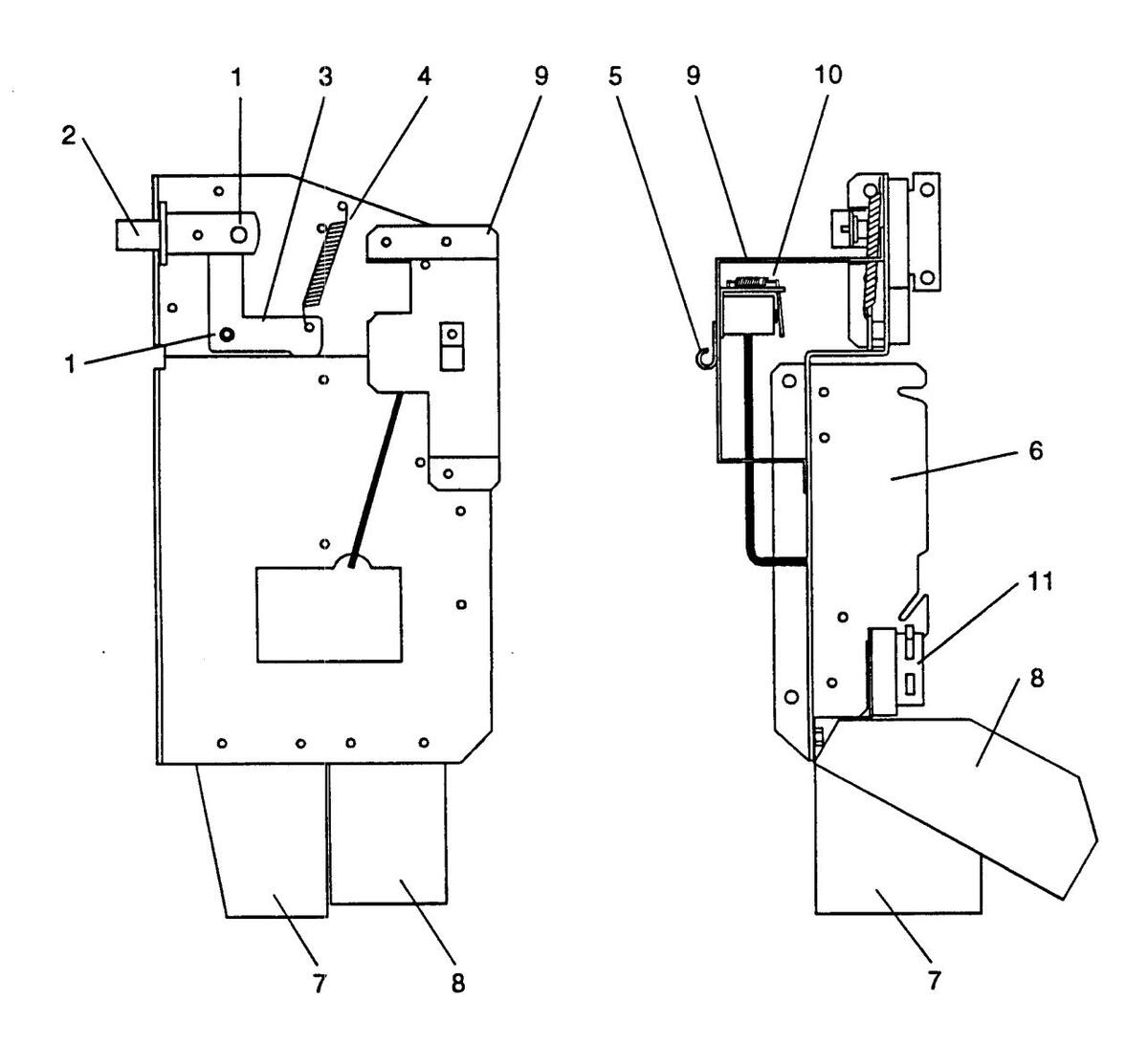
Figure 8-6. Coin Acceptor
| ***** | ||
|---|---|---|
| Ref. | Part No. | Description Qty |
| **** | ||
| 1 | 70143003 | External Retaining Ring2 |
| 2 | 25056504 | Button & Blade Assembly - Reject1 |
| 3 | 35143702 | Actuator Bracket (C-8 & C-10)1 |
| 4 | 21083601 | Tension Spring1 |
| 5 | 70093103 | Cable Clamp (1/4) 1 |
| 6 | 30984404 | Coin Mech Holder Assembly1 |
| 7 | 35144101 | Coin Chute (Reject) 1 |
| 8 | 35144001 | Coin Chute (Accept)1 |
The Following Parts Are Used With Mechanical Coin Acceptors Only:
| 9 | 35174301 | Magnetic Lockout Bracket | I |
|---|---|---|---|
| 10 | 35031703 | Lockout with Magnet (IMONEX) | 1 |
| 11 | 21990203 | Switch & Bracket Assembly | 1 |
Parts Not Shown:
| 25553201 | Stop Bracket (Reject Lever)1 |
|---|---|
| 45108902 | Coin Box Assembly (C-8 and C-10)1 |
| 45108301 | Harness Assembly - Computer to Coin Acceptor (Mechanical) |
| 45108302 | Harness Assembly - Computer to MARS 330 Coin Acceptor |
| 45108303 | Harness Assembly - Computer to Coin Controls C120 |
| 45108304 | Harness Assembly - Computer to Microcoin S5 |
Figure 8-7. C-8, C-10 Coin Dispenser Assembly
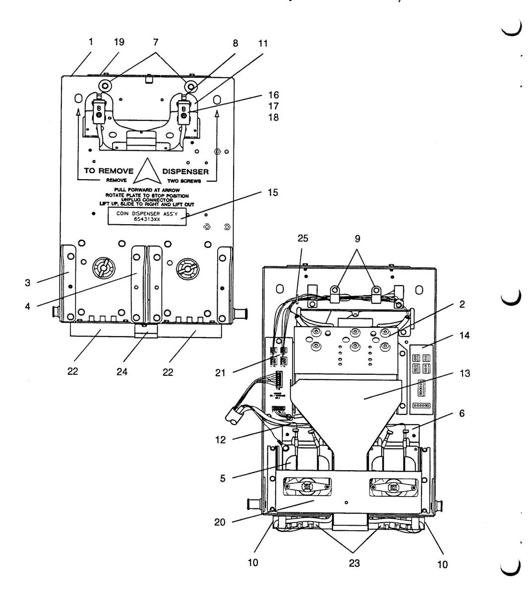
| Ref. | Part No. | Description | Qty |
|---|---|---|---|
| ********* | 65431302 | C-8 Dispenser Assembly - Coin | Pof |
| 65431301 | C-10 Dispenser Assembly - Coin | Ref. | |
| 05 15 1501 | |||
| Both | the C-8 and C | C-10 use the same components, except as noted. | |
| 1 | 45035311 | Frame and Pivot Assembly | 1 |
| 2 | 45032620 | Change Bucket Assembly (See Figure 8-8) | 1 |
| 3 | 35044701 | Hopper Mounting Bracket (L.H.) C-8 | ••••• |
| 35044702 | Hopper Mounting Bracket (L.H.) C-10 |
-
|
|
| 4 | 35044801 | Hopper Mounting Bracket (R.H.) C-8 |
ہ
4 |
| 35044802 | Hopper Mounting Bracket (R.H.) C-10 |
۔
4 |
|
| 5 | 35049102 | Hopper Drive Motor Assembly | |
| 45034102 | Hopper Drive Motor | 1 | |
| 45034001 | Coupling - Ratchet | ||
| 25097701 | Spring - Compression | ||
| 70120904 | Washer (Nylon) | ||
| 70110126 | Pin - Groove | ||
| 37004601 | Gear Box | ||
| 6 | 35046401 | Mounting Bracket (Motor) | |
| 7 | 25112701 | Rubber Bumper | |
| 8 | 45076101 | Holder Assembly - LED | |
| 70035315 | |||
| 9 | 70093105 | Cable Clamp (3/8) | |
| 10 | 70093401 | Cable Clamp (1/2) | |
| 11 | 45035006 | Chute Assembly | |
| 12 | 65065340 | Dispenser Harness Assembly | |
| 13 | 35068202 | Chute Assembly - Coin Weld (BC-1200 Only) | |
| 14 | 25169107 | Dispenser Wiring Label | |
| 15 | 25189421 | Label - Coin Dispenser (65431302) C-8 | |
| 25189420 | Label - Coin Dispenser (65431301) C-10 | ||
| 16 | 25175702 | Photo Detector Board and Terminal Assembly | |
| 17 | 70121626 | Spacer (Nylon) | |
| 18 | 35048202 | Cover - Terminal Board | |
| 19 | 35125402 | ||
| 20 | 45042602 | Guard - Dispenser Motor | |
| 21 | 45076403 | Circuit Board Assembly - Interconnect | ••••• |
| ~ ' | 70035006 | Diode | ••••• |
| 22 | 35142801 | Contact Mounting Bracket | |
| 22 | 25552401 | Board and Spring Contact Assembly | ••••• |
|
∠_)
71 |
25200001 | Extension - Coin Chute | ••••• |
|
24
25 |
70800101 | ••••• | |
| Z .J | / 0000101 |

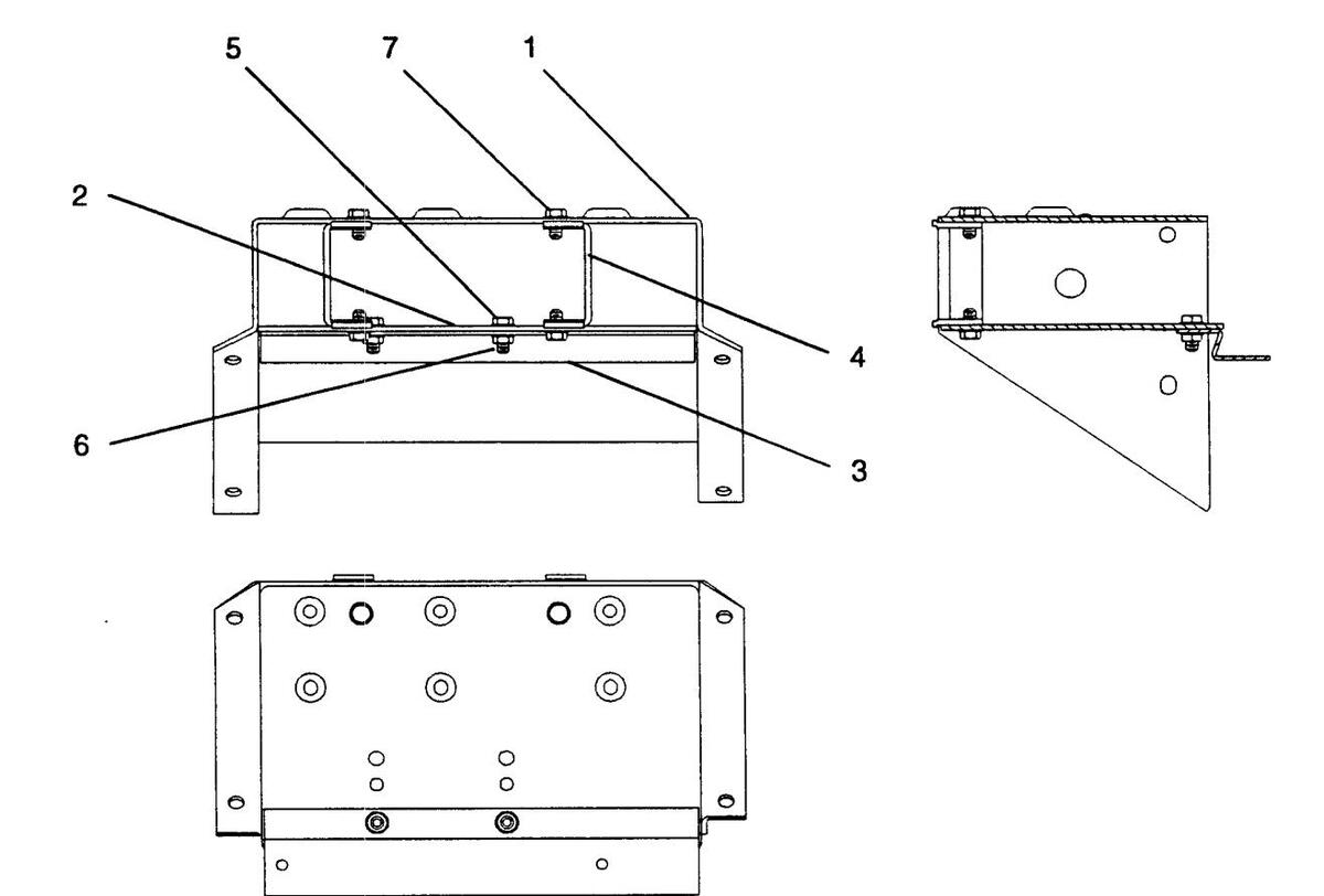
| Ref. | Part No. | Description | Qty |
|---|---|---|---|
| ****** | |||
| 45032620 | Change Bucket Assembly | . Ref. | |
| 1 | 45033306 | Bucket Frame | 1 |
| 2 | 35047002 | Plate - Front, Bucket | 1 |
| 3 | 25112402 | Dispenser Chute Mounting Bracket | 1 |
| 4 | 25112902 | Support Bracket | 2 |
| 5 | 80443006 | Screw – #8-32 x 3/8 HWHM, SF | 2 |
| 6 | 87843000 | Nut – #8-32 KEPS | 2 |
| 7 | 80443004 | Screw – #8-32 x 1/4 HWHM, SF | 4 |
| • • |
Figure 8-9. Electrical Box Assembly
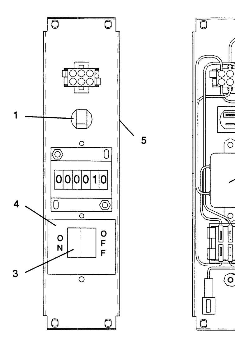
Figure 8-9. Electrical Box Assembly
×1
2
0
| ********* | ||
|---|---|---|
| Ref. | Part No. | Description Qty |
| 45085303 | Electrical Box Assembly (See Figure 8-3) | |
| 1 | 70073608 | Circuit Breaker (5 Amp)1 |
| 2 | 35131102 | Filter & Lug Assembly |
| 3 | 30785702 | Rocker Switch (DPST)1 |
| 4 | 25250101 | Label - On-Off |
| 5 | 45085402 | Box - Electrical |
C-8, C-10 Accessory Kits
| Qty. | Description | Part No. |
|---|---|---|
| Heavy Duty Base Kits | ||
| 1 | Heavy Duty Base Kit C-6, C-8, C-10 | 27063602 |
| Light Duty Base Kits | ||
| 1 | Light Duty Base Kit C-6, C-8, C-10 | 27044002 |
| Top Filler Kits | ||
| Top Filler Kit C-8 | 27044103 | |
| Top Filler Kit C-10 | 27044104 | |
| Kit-Lock Guard | ||
| Kit-Door Guard C-8 | 27041704 | |
| 1 | Kit-Door Guard C-10 | 27041705 |
| Accepted Bills Labels | ||
| $1 & $5 | 35143902 | |
| $1, $5 & $10 | 35143903 | |
| $1, $5, $10 & $20 | 35143904 | |
| $5 & $10 | 35143906 | |
| 1 | $5, $10 & $20 | 35143907 |
| Token Label | ||
| Label - Tokens | 35175101 |
,


 Loading...