

Page 1

WiFly Serial Adapter Install Guide
WiFly Serial Adapter_bp-ig 8/10/09
WIFLY SERIAL ADAPTER
RN-370 & RN-374
Battery Powered 802.11 b/g Serial
Adapter
Install Guide and User Manual
Version 1.00
Sept 19th 2009
Copyright © 2009 Roving Networks, Inc. All Rights Reserved.
The contents of this document can be changed by Roving networks without prior notice and
do not constitute any binding undertakings from Roving networks. Roving Networks is not
responsible under any circumstances for direct, indirect, unexpected or consequent
damage that is caused by this document.
Page 2

Overview
The Battery powered WiFly Serial Adapter supports either RS-232 (RN-370) or
RS-422 (RN-374) interfaces. When connected to a remote host, the WiFly
serial adapter transfers data read or written to the serial interface to a remote
application such as an iPhone app, data logger or PC control console. Data is
transferred over a reliable TCP/IP socket. 802.11 b/g infrastructure or adhoc
networking has the advantage of using existing, low cost wireless connectivity
and being able to remotely connect to any WiFly serial adapter in the world.
The WiFly serial adapter is powered by two AAA batteries, an external AC to
5VDC power brick, or 5VDC (only !) on pin 9 of the DB9 connector.
Rechargeable NiMH batteries will be trickle charged when used with an external
5VDC (only !) power source. The WiFly Serial Adapter will run for up to 8 hours
while connected over WiFi on a fully charged set of batteries.
Since Apple Computer requires an additional Bluetooth authorization coprocessor for any and all devices connecting to the iPhone, using the WiFi serial
adapter in adhoc mode is a simple and cost effective way to connect to iPhone
apps. The WiFly Serial Adapter is more than a cable replacement solution. By
allowing multiple TCP/IP sockets, applications can control and monitor hundreds
of Wifi Serial adapters remotely distributed across a building LAN or campus
WAN.
Other usage modes can be setup. When configured in auto connect mode, the
WiFly Serial Adapter will connect out to a pre-stored IP address whenever data
is written to the serial port. The WiFly Serial Adapter can also be set to
automatically go to sleep once idle, and wakeup based on time delay, or UART
RX data or state change of CTS signals.
Powering up the WiFly Serial Adapter
The red button on the top of the WiFly Serial Adapter is a soft ON/OFF switch.
The WiFly Serial Adapter can be powered from batteries or from the external
power connector.
Warning: Do NOT use alkaline batteries when connecting the external
power. Doing so will cause permanent damage. The WiFly Serial
Adapter will operate on 5VDC power with no batteries installed.
To turn ON the WiFly Serial Adapter, press down the red button for 1 second,
then release it. You will see the green, yellow, red and blue LEDs flash in
succession. After a moment the blue and yellow LEDs will go OFF, leaving the
red and green LED flashing.
Page | 2
www.rovingnetoworks.com support@rovingnetworks.com
Roving Networks, 809 University Ave. Los Gatos Ca. 95032
Page 3
9
9
9
9
9
9
9
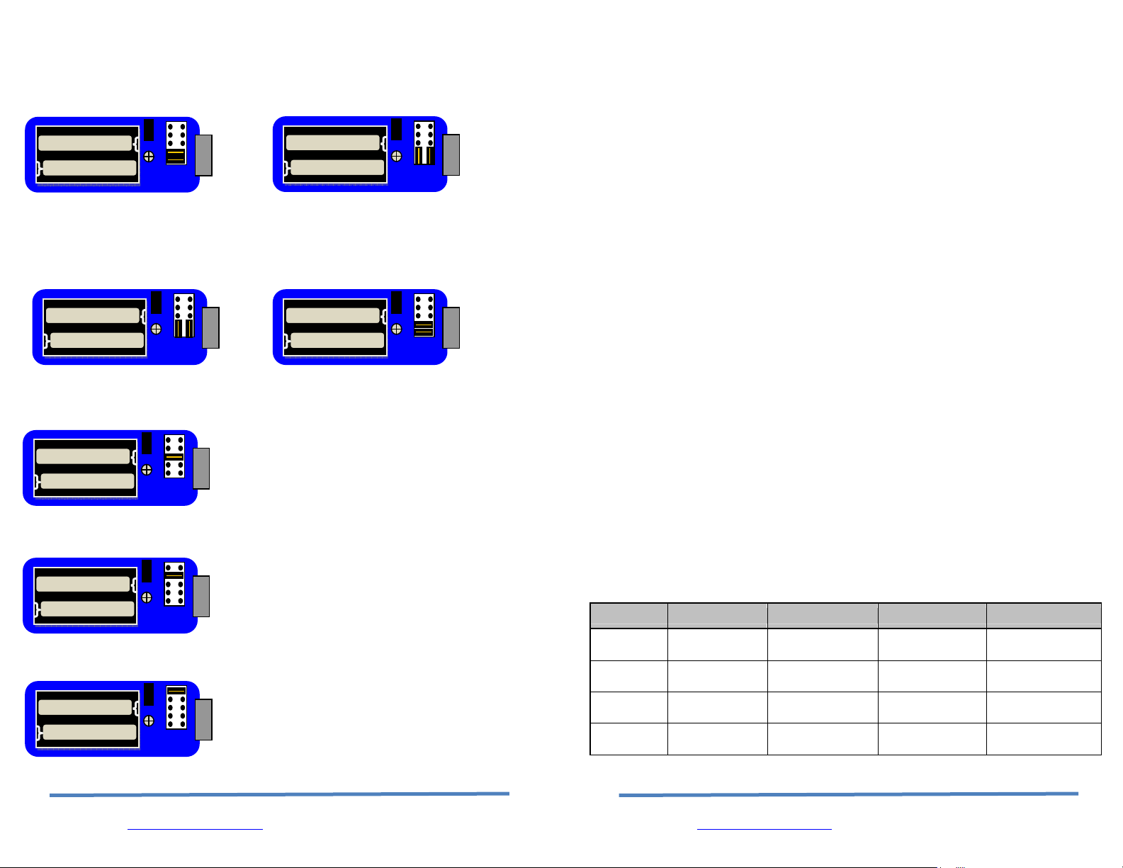
Male DB9 (Default Config) Male DB9 - Null Modem
Jumper 1<>2, 3<>4 Jumper 2<>4, 1<>3
10
8
7
6
5
4
3
2
1
10
8
7
6
5
4
3
2
1
Female DB9 (Default Config) Female DB9 - Null Modem
Jumper 2<>4, 1<>3 Jumper 1<>2, 3<>4
10
8
7
6
5
4
3
2
1
10
8
7
6
5
4
3
2
1
Drive DSR on pin 6 of the male DB9
Jumpper 5<>6
10
8
7
6
5
4
3
2
1
Drive DTR on pin 4 of the male DB9
Jumpper 7<>8
10
8
7
6
5
4
3
2
1
Drive DCD on pin 1 of the male DB9
Jumpper 9<>10
10
8
7
6
5
4
3
2
1
To turn OFF the WiFly Serial Adapter, press down on the red button for 1
second, then release it. The green, yellow, red and blue LEDs flash in
succession several times. Then All the LEDs will turn off and the device will be
in sleep mode.
By default the WiFly Serial Adapter automatically shuts itself off if not
connected for more than 3 minutes = 180 seconds. The sleep timer duration is
controlled by using the set system sleep <seconds> command. Use the get
sys to display the current settings of the sleep timer.
Batteries and Charging
Only use NiMH rechargeable batteries (or no batteries) when externally
powering the WiFly Serial Adapter. Applying power with alkaline batteries
will damage the device and could cause a fire hazard.
The red LED near the power connection comes on SOLID when external power
is present. When turning on the WiFly Serial Adapter a BLINKING blue LED
indicates low battery. Battery life between charges depends on use. With
typical usage you should get at least 8 hours of continuous use between
charges. Enabling sleep modes can extend the battery life.
External power can be applied from either the 5 VDC plug or pin 9 on the DB9
connector. The power plug is center pin positive, outer cylinder GND. Input
MUST be 5 VDC for proper battery charging. Higher voltages can permanently
damage the charger and battery.
In configuration mode the show bat command will return the current battery
voltage. Note that with rechargeable NiMh batteries the voltage will remain
relatively unchanged just until they go dead.
Status LEDs
State Green LED Yellow LED Red LED Blue LED
ON solid
Fast blink
Slow blink IP address OK
OFF
Connected
over TCP
No IP address
or Config Mode
Full charge
Not Associated
Associated, No
Internet
Associated,
Internet OK
Rx/Tx data
transfer
Low Power
Page | 26
www.rovingnetoworks.com support@rovingnetworks.com
Roving Networks, 809 University Ave. Los Gatos Ca. 95032
Page | 3
www.rovingnetoworks.com support@rovingnetworks.com
Roving Networks, 809 University Ave. Los Gatos Ca. 95032
Page 4
4
The blue LED blinks when data is sent or received on the serial interface. This
does not indicate that the data was sent over the WiFi connection. If the blue
LED is not flashing and your device is sending data to the serial port, you likely
have a connection, incorrect baudrate, or HW flow control (RTS/CTS) problem.
The blue LED also indicates battery status and will blink slowly when the
batteries are low except when charging. When charging the blue LED remains
off. If the device is on while the batteries are charging the blue LED will come
solid when the batteries are fully charged
When using switch1 to enable adhoc mode, after the device powers on, all LEDs
will blink in succession from green to blue. This does not occur when adhoc
mode is set through software.
There is an additional red LED near the power connector that indicates external
power is present at either the power plug of DB9 connector.
Configuration Switches
The configuration switches on the top of the WiFly Serial Adapter are small.
You will need a paper clip or small screw driver to change them. Hold the
devices with the DB9 connector facing to the right, the switches are numbered
one to four from bottom to top. The off position is towards the DB9 connector.
Switch 1 – Adhoc and restoring factory defaults
With this switch ON, the device powers up in adhoc mode. The SSID of the
adhoc network will be Wifly-GSX-NN where NN is the last two digits of the
devices mac address.
To restore factory defaults, power on the device with this switch ON, then
toggle the switch five (5) times. If there is a config file named "user" on the
WiFly Serial adapter file system, it is read in as the factory defaults instead of
using the hardcoded defaults. If no "user" config file is present, the hardcoded
factory defaults are used.
Page | 4
www.rovingnetoworks.com support@rovingnetworks.com
on off
3
2
Roving Networks, 809 University Ave. Los Gatos Ca. 95032
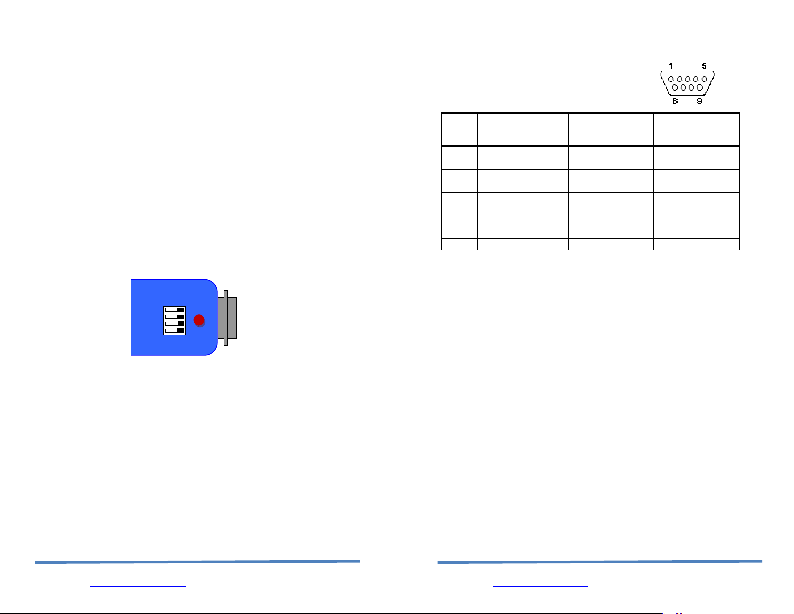
Serial Connector Specification
DB9 connector Pin Out
Pin
RN-370M
Male DB9
1 NC NC NC
2 RXD TXD NC
3 TXD RXD RXD4 NC NC TXD+
5 GND GND GND
6 NC NC +5 VDC (input)
7 RTS CTS RXD+
8 CTS RTS TXD9 4-12VDC 4-12VDC NC
NOTE: The RS422 interface uses the MAX490 transceiver. This device is
designed to operate with input voltage range of 4.75 to 5.25 VDC.
RXD+ and TXD+ each have a 4.7K pull up to 5VDC.
RXD- and TXD- each have a 4.7K pull down to GND.
NOTE: The RS232 interface uses the SIPEX SP3232ECA chip with capacitor
switch to generate the + and – signals and thus is not driving the full RS232
voltages. Devices stealing power from the RS232 pins may not have enough
voltage.
Null modem and Flow control Jumpers
The WiFly Serial Adapter 370M serial interface can be configured to enable flow
control and null modem signaling. The Jumper block is accessed by removing
the battery cover from the WiFly serial adapter.
WARNING: flow control signals are NOT RS232 signaling tolerant. If these are
enabled with the jumper do not exceed 3.3 VDC or permanent damage can
occur.
Page | 25
www.rovingnetoworks.com support@rovingnetworks.com
Roving Networks, 809 University Ave. Los Gatos Ca. 95032
RN-370F
Female DB9
RN-374M
Male DB9
Page 5

Low Power Mode
The "user" config file is created using the "save user" command which saves
the current configuration settings.
Even if there is a “user” config file arming and toggling this switch seven (7)
times will override the “user” settings and restore the wifly module to the
factory hardcoded defaults. This is a bypass mechanism in case a bad
configuration is saved into the “user” file.
Switch 2 – Sensor pin 2
Currently not used
Switch 3 – Sensor pin 3
Currently not used
Switch 4 – Sensor pin 7
Currently not used
WiFi Connections
The WiFi serial adapter is used to create a WiFi connection to a variety of
application, some examples are:
• Remote environmental sensors
• Linking mobile devices like GPS and light sensors
• Automotive diagnostics
• Industrial equipment monitoring and control
The WiFly Serial adapater can be configured in a Point to point (Adhoc) or
Infrastructure Networking setup. In the point to point setup the WiFly serial
adapter is connected via adhoc to an iPhone, Smartphone or laptop computer to
download the data or control a remote device through the serial interface.
With the Network setup the WiFly Serial Adapter associates with an access point
and is reachable from any machine on the LAN. You can extend this access to
anywhere on the internet by using Dynamic DNS. The Network setup is useful
when the WiFly serial adapter is making connections to a server and uploading
data.
Creating a Point to Point setup
Page | 24
www.rovingnetoworks.com support@rovingnetworks.com
Roving Networks, 809 University Ave. Los Gatos Ca. 95032
Page | 5
www.rovingnetoworks.com support@rovingnetworks.com
Roving Networks, 809 University Ave. Los Gatos Ca. 95032
Page 6

The WiFly Serial adapter can be configured for adhoc network via hardware or
software commands. In Adhoc mode the device looks like access point so that
other WiFi devices to join WiFly adhoc network and open connections to the
WiFly serial adapter.
Note: currently the WiFly only supports OPEN mode for creating adhoc
networks.
Adhoc mode can be enabled via hardware or software configuration. To enable
Adhoc mode via hardware turn ON external switch 1. When the module
powers up the LEDS will blink in sequence and an adhoc network will be created
with the following
SSID: WiFly-GSX-XX where XX is the final two bytes of the devices MAC
address
Channel: 1
DHCP: OFF
IP address: 169.254.1.1
Netmask: 255.255.0.0
When Switch 1 is ON the above settings override any set configuration
settings.
To enable adhoc mode from software configuration, enter into command mode
and set the follow configuration. Adhoc mode is turned on by setting the join
mode to 4. You will also need to set the ssid and channel.
set wlan join 4
set wlan ssid my_adhoc_network
set wlan chan 1
Turn off DHCP and set the IP address and netmask so other devices know
where to connect to the adhoc WiFly GSX. Since auto IP fixes the first two
bytes of the IP address you want to use the netmask of 255.255.0.0 so that
other device connecting to the module can be reached. Alternatively you can
set the netmask to a smaller subnet if the other device’s IP addresses are begin
statically to the same subnet as the adhoc device
set ip address 169.254.1.1
set ip netmask 255.255.0.0
set ip dhcp 0
Be sure to save your configuration, then upon reboot the module will be in
adhoc mode.
To associate with the WiFly serial adapter from an iPhone, Smart phone or
computer. Open the dialog box or window that shows the available networks.
ftp update <name> Updates firmware with the latest release.
Deletes the backup image, retrieves new
image and updates the boot image.
Page | 6
www.rovingnetoworks.com support@rovingnetworks.com
Roving Networks, 809 University Ave. Los Gatos Ca. 95032
Page | 23
www.rovingnetoworks.com support@rovingnetworks.com
Roving Networks, 809 University Ave. Los Gatos Ca. 95032
Page 7

should be set with the set ip gateway
<addr> command
ping h pings the stored host IP address, the host IP
address can be set with the set ip host
<addr> command
reboot forces a reboot of the device (similar to
power cycle)
scan <time> Performs an active probe scan of access
points on all 13 channels. Returns MAC
address, signal strength, SSID name,
security mode.
Default scan time is 200ms / channel =
about 3 seconds.
time is an optional parameter, this is the
time in ms per channel.
For example, “scan 30” reduces the total
scan time down to about 1 second. This
command also works in Adhoc mode
(version 2.11).
time Sets the Real time clock by synchronizing
with the time server specified with the time
server parameters (see section 0) This
command sends a UDP time server request
packet
FILE IO Commands
load <name> Reads in a new config file.
ls Displays the files in the system
save Saves the configuration to “config” (the
default file).
save <name> Saves the configuration data to a new file
name
boot image <num> Makes file <num> the new boot image.
On the iphone this is in the settings icon. On Microsoft Windows this is the
“Control Panel / Networking and Sharing / Networking and Sharing Center”
dialog.
Find the name of the WiFly Serial Adapter adhoc network in the list of available
networks and select it to associate.
Note: Once associated with the adhoc network, (since there is likely no active
DHCP server) Auto-IP is used. This may take a couple minutes to allocate an IP
address for your computer. To work around this you can assign a static IP
address in the network settings / TCP/IP / Properties menu.
Once associated with the adhoc network you can open a connection or telnet
window as you would with an infrastructure mode connection. See the section
below “Opening a Connection”
Note: The module does not support adhoc and enterprise network modes
simultaneously.
Creating a network setup
From command mode you can view available network, associate to a network
and see status of the network connection.
To find all available networks use the scan command.
If the access point you’re associating with is running in open mode (no security)
you can simply use the join my_network command to associate with it.
If the access point is security enabled you will need to set the pass phrase (WPA
modes) or key (WEP modes) prior to issuing the join command. The Wifly
Serial adapter will inquire and determine the security protocol used by the
access point so you do not have to set the authentication mode. To set the
pass phrase for WPA use the command set wlan phrase <string>. For WEP
set the key using the set wlan key <num> command.
To configure the WiFly serial adapter to remember network, use the command
set wlan ssid my_network. Next save the SSID and Pass Phrase/Key to the
configuration file using the save command. Next time the device powers up it
will used the save network information to associate with the network.
set wlan ssid my_network
set wlan phrase my_secret_code
save
reboot
Page | 22
www.rovingnetoworks.com support@rovingnetworks.com
Roving Networks, 809 University Ave. Los Gatos Ca. 95032
Page | 7
www.rovingnetoworks.com support@rovingnetworks.com
Roving Networks, 809 University Ave. Los Gatos Ca. 95032
Page 8

For security reason you may want to hide the Pass Phrase/Key. This is
accomplished using the set wlan hide command. To un-hide the Pass Phrase,
reset the key or passphrase.
Action Commands
$$$ enter command mode Characters are
PASSED until this exact sequence is seen. If
any bytes are seen before these chars, or
after these chars, in a 250ms window,
command mode will not be entered and
these bytes will be passed on to other side.
close disconnect a TCP connection.
exit exit command mode. Exit command mode.
“EXIT” will be displayed.
factory RESET Loads factory defaults into the RAM
configuration. Note that the RESET must
be capitalized. After this command the
new settings must be save to the config file
using the save command and the module
rebooted for them to take effect.
join <ssid> joins the network <ssid>. If network is
security enabled you must set the pass
phrase with the set wlan phrase command
prior to issuing the join command
leave disconnects from currently associated
Access Point.
open <addr> <port> opens a TCP connection to the given IP port
and address. If no arguments are provided,
the device will attempt to connect to the
stored remote host IP address and remote
port number. <addr> can also be a DNS
hostname and will be resolved if entered.
Ping <g | h | i | addr> <num> ping remote host. Default sends 1
packet. Optional <num> sends <num>
pings at 10 per second.
Ping 10.20.20.12 10 – pings IP address 10
times
ping g pings the gateway, the gateway IP address
is loaded if DHCP is turned on, otherwise it
Page | 8
www.rovingnetoworks.com support@rovingnetworks.com
Roving Networks, 809 University Ave. Los Gatos Ca. 95032
Page | 21
www.rovingnetoworks.com support@rovingnetworks.com
Roving Networks, 809 University Ave. Los Gatos Ca. 95032
Page 9

For example, if the ssid of the AP is “yellow
brick road”
You would enter “yellow$brick$road”
Using the ‘get w” command will properly
display the value:
SSID=yellow brick road.
Display commands:
get everything displays all configuration settings, useful for
debug.
get com display comm. settings.
get ip display IP address and port number
settings.
get optional display the optional settings like device ID
get sys display system settings, sleep, wake timers,
etc.
get time display the time server UDP address and
port number.
get wlan display the ssid, chan, and other wlan
settings.
get uart display the UART settings.
show battery Displays current battery voltage
show net Displays current network status, association,
authentication, etc.
show stats Displays current statistics, packet rx/tx
counters, etc.
show time Displays number of seconds since last
powerup or reboot
ver return the software release version
Page | 20
www.rovingnetoworks.com support@rovingnetworks.com
Roving Networks, 809 University Ave. Los Gatos Ca. 95032
Connection Modes
Two common modes of operation for the Wifly Serial adapter are A: initiating a
connection to a server and B: listening for a remote host connection. This
section will go through the configuration for each of these setups. The set ups
are shown using infrastructure network. i.e. with an access point, however the
same can be done with adhoc networking.
Initiating a connection from the WiFly serial adapter
Step 1: Set up the wlan properties so the device will connect to the network
automatically upon power up. In this example we want to connect to the wireless
network my_network.
set wlan join 1 // Auto join upon power up
set wlan chan 0 // Scan all channels
set wlan ssid my_network // Network name
set wlan phrase my_secret_code // Pass phrase
The join 1 setting ensures that when the module wakes up, it tries to join the
access point that matches the stored SSID, passkey and channel. Channel =0 (the
default) will force auto-scanning. Setting the channel will reduce the time it takes
the WiFly to find and associate.
Step 2: Set up the IP address and port number of the remote server, so the WiFly
serial adapter can connect when it wakes up.
set ip host 10.20.20.75 // Set the host IP address
set ip remote 3000 // Set the remote port
set sys autoconn 2 // Try to connect to the host every 2 seconds
save // Save configuration>
Note: If autoconn=1, the WiFly will only make one attempt to auto connect.
Step 3: Set the wake up and sleep conditions. By default the serial adapter will
wake whenever there is data written to the serial interface. You can also
configure the device to wake up on CTS, on a PIO or timer. See the WiFly GSX
user manual for details. We are going to set this up to wake on a timer then
sleep after 2 minutes if there is no connection or if connected and no data has
been transferred for 30 seconds.
set sys sleep 120 // sleep after 2 minutes if no connection
set sys trigger 2 // wake on CTS
Page | 9
www.rovingnetoworks.com support@rovingnetworks.com
Roving Networks, 809 University Ave. Los Gatos Ca. 95032
Page 10

set conn idle 30 // disconnect after 30 seconds of no data
save // save all the settings to the config file
reboot // use the new settings
This setup can be tested using TCP server application that opens a socket on
port 3000. Port Peeker is a free application that you can download off the web.
It is available at
Waiting for the remote host to connect to the serial adapter (listen mode)
http://www.linklogger.com/portpeeker.htm
In this example we are using a static IP so that the remote host knows where the
WiFly Serial adapter is on the network. Alternatively you can write your application
software to listen for the broadcast UDP packet (automatically sent by WiFly by
default) to identify the WiFly Serial adapter and get the IP address and TCP port
number that the WiFly is listening on.
Step 1: Set up the wlan properties so the device will connect to the network
automatically upon power up. In this example we want to connect to the wireless
network my_network.
set wlan join 1 // Auto join upon power up
set wlan chan 1 // only look on channel 1
set wlan ssid my_network // Network name
set wlan phrase my_secret_code // Pass phrase
Step 2: Configure the WiFly static IP address so the remote application can
connect, turn off DHCP and set the IP address and netmask.
set ip address 10.20.20.63 // Set the IP address
set ip port 5030 // Set the local port to listen on
set ip netmask 255.255.255.0 // Set the IP netmask
set ip gateway 10.20.20.1 // Sets the network gateway
set ip dhcp 0 // Turn off DHCP
Step 3: Set the wake up and sleep conditions. In this mode the sleep and wake
timers are used to conserver battery. Since we don’t know when the remote
host will connect, the module should to occasionally wake up and listen for the
remote host. The trade of with these timers is the longer you sleep the better
battery performance but the longer the latency the remote host sees when
Page | 10
www.rovingnetoworks.com support@rovingnetworks.com
Roving Networks, 809 University Ave. Los Gatos Ca. 95032
The Wifly GSX only supports “open” key
mode, 128 bit keys for WEP. WEP-128,
shared mode is not supported as it is known
to be easily compromised and has been
deprecated from the WiFi standards.
set wlan mask <value> sets the wlan channel mask used for
scanning channels with the auto-join policy
1 or 2, used when the channel is set to 0.
Value is a bit-map where bit 0 = channel 1.
Input for this command can be entered in
decimal or hex if prefixed with 0x. Default
value is 0x1FFF (all channels)
set wlan num <value> sets the default WEP key to use. 1-4 is the
valid range.
Example : “set w n 2” sets the default key
to 2.
set wlan phrase <string> sets the passphrase for WPA and WPA2
security modes. 1-64 chars. The
passphrase can be alpha and numeric, and
is used along with the SSID to generate a
unique 32 byte Pre-shared key (PSK), which
is then hashed into a 256 bit number.
Changing either the SSID or this value recalculates and stores the PSK.
If exactly 64 chars are entered, it is
assumed that this entry is already an ASCII
HEX representation of the 32 byte PSK and
the value is simply stored.
Example : “set w p password” sets the
phrase.
set wlan ssid <string> sets the wlan ssid to associate with. 1-32
chars.
NOTE: If the passphrase or ssid contain the
SPACE ( ‘ ‘)
characters, these can be entered using
substitution via the “$” character.
Page | 19
www.rovingnetoworks.com support@rovingnetworks.com
Roving Networks, 809 University Ave. Los Gatos Ca. 95032
Page 11

scanning. (Default)
2 Join ANY access point with
security matching the stored
authentication mode. This
ignores the stored SSID and
searches for the access
point with the strongest
signal. The channels
searched can be limited by
setting the channel mask.
3 Reserved – Not used
4 Create an Adhoc network,
using stored SSID, IP
address and netmask.
Channel MUST be set.
DHCP should be 0 (static IP)
or set to Auto-IP with this
policy. (unless another
Adhoc device can act as
DHCP server)
This policy is often used
instead of the hardware
jumper to creat a custom
Adhoc network
set wlan hide <0, 1> Hides the WEP key and WPA passphrase.
When set, displaying the wlan settings
shows ****** for these fields. To unhide
the passphrase or passkey, re-enter the key
or passphrase using the set wlan key or set
wlan passphrase command. Default = 0,
don’t hide.
wlan key <value> sets the 128 bit WEP key. If you are using
WPA or WPA2 you should enter a pass
phrase with the set wlan passphase
command. Key must be EXACTLY 13 bytes
(26 ASCII chars). Data is expected in HEX
format, “0x” should NOT be used here.
Example : “set w k
112233445566778899AABBCCDD”
Hex digits > 9 can be either upper or lower
case.
Page | 18
www.rovingnetoworks.com support@rovingnetworks.com
Roving Networks, 809 University Ave. Los Gatos Ca. 95032
connecting. WARNING: do not set the sleep timer below 5 seconds or it will be
impossible to get into command mode to reprogram this mode without it going
back to sleep.
set sys wake 20 // Wake after 20 seconds
set sys sleep 10 // Go to sleep after 10 seconds
save // Save configuration
reboot // restart using the new configuration
At this point you could test this configuration using telnet on a computer sharing
the same network to connect to the WiFly serial adapter.
Device Configuration
The WiFly Serial adapter can be thought of as a data pipe. Any data read or
written into the serial interface appears on the TCP/IP socket and vice versa.
Configuration is accomplished over the same data pipe. You enter command
mode with the three character escape sequence, $$$. While in configuration
mode all characters sent over the data pipe are interpreted by the WiFly Serial
adapter as command. The “exit” command returns the device to data transfer
mode.
The WiFly module can be configured both locally through the Serial connection
with a terminal emulator or remotely over the air via a Telnet connection. Serial
configuration is the simplest in that you do not have to set adhoc mode and
associate with the network.
NOTE: We suggest using TeraTerm. It has both a terminal emulator and Telnet
capability. This is available for download from the Roving Networks website.
http://www.rovingnetworks.com/support/teraterm.zip
Local configuration over the serial port
Connect the WiFly Serial Adapter to the serial port your computer. You may
need a null-modem cable (DB9 pins 2 and 3 swapped) if you have a RN-370M
or a straight cable if you have a RN-370F. If your computer does not have a
serial port you can use a USB serial cable such as the RN-USB-SERIAL to
connect the WiFly Serial Adapter to your computer.
The RN-374 will require a RS422 to RS232 converter or RS422 to USB cable to
connect the WiFly Serial Adapter to your computer.
• With the WiFly Serial Adapter connected and powered on, locate using
Page | 11
www.rovingnetoworks.com support@rovingnetworks.com
Roving Networks, 809 University Ave. Los Gatos Ca. 95032
Page 12

the device manager which COM port the serial interface or serial USB is
connected to.
• Next open up a terminal emulation program specifying the COM port
found in the previous step. If using TeraTerm, select Serial and choose
the COM Port from the pull down list.
Note: the default serial port setting is 9600, 8 bit, no parity.
• From within the terminal window, put the WiFly GSX module into
command mode by typing $$$ in the terminal window. You should get
CMD back confirming you are in command mode.
Remote connection over the air via a Telnet
First you must create an adhoc network and join the network from your computer.
Once the computer is on the same network you can open the telnet connection to
the module. Use ping to see if the Wifly serial adapter can be seen on the network
from the computer.
• Enable adhoc mode by turning on switch 1, power on the WiFly Serial
adapter.
• Associate to the Adhoc network from your computer. Use ping to verify
the WiFly serial adapter is visible on the network.
• Start TeraTerm and select the TCP/IP radio button. You will need to set
the IP address of the module which will be 169.254.1.1. Also select the
Telnet radio button and set the port to 2000. Hit OK
• The module will reply with the string *HELLO* indicating that the
connection has been established.
Getting into command mode
Type $$$ (3 dollar signs) into the terminal emulator or telnet window, you
should see CMD returned to you. If you see CMD you know that your
connection and terminal settings are correct.
Entering <CR> command returns a prompt <x.xx> where x.xx is the version
number of the firmware running. Invalid syntax returns ERR: ?-Cmd, and
incorrectly formatted commands return ERR: Bad Args or ERR: 2few Args
To exit command mode type exit. You will see EXIT echoed to indicate the
module is in data mode.
Example : “set u b 9600” sets the baud rate
to 9600 baud.
NOTE: the RS-232 interface on the RN-370
does not work reliably above 230400
set uart instant <rate> This immediately changes the baudrate.
This is useful when testing baudrate
settings, or switching baudrate “on the fly”
remotely while connected over TCP. This
setting does not affect configuration.
Returns the AOK response, and then this
command will exit command mode.
set uart raw <rate> sets a RAW UART value. Used to set non-
standard rates. The lowest possible baud
rate is 2400.
Example : “set u r 7200” sets the baud rate
to 7200 baud.
set uart flow <0,1> sets the flow control mode. Default=0=off,
1= hardware RTS/CTS.
NOTE: Due to an issue in the UART
hardware, the UART does not support even
or odd parity.
WLAN Parameters
set wlan channel <value> sets the wlan channel, 1-13 is the valid
range for a fixed channel. If 0 is set, then
scan is performed, using the ssid, for all the
channels set in the channel mask.
set wlan join <value> sets the policy for automatically
joining/associating with network access
points. This policy is used when the module
powers up, including wake up from the sleep
timer.
Value Policy
0 Manual, do not try to join
1 Try to join the access point
that matches the stored
SSID, passkey and channel.
Channel can be set to 0 for
Page | 12
www.rovingnetoworks.com support@rovingnetworks.com
Roving Networks, 809 University Ave. Los Gatos Ca. 95032
Page | 17
www.rovingnetoworks.com support@rovingnetworks.com
Roving Networks, 809 University Ave. Los Gatos Ca. 95032
Page 13

TIME Server Parameters
set time address <addr> sets the time server address. (sNTP servers)
set time port <num> sets the time server port number. Defaults
to 123 which is almost always the sNTP
server port.
set time enable <value> Enable or disable fetching time from the
specified sNTP time server. Default=0=
disabled. A value or 1 gets time only once
on power up. Any value > 1 gets time
continuously every <value> minutes.
SYSTEM Parameters
set sys autoconn <secs> TCP mode: sets the auto connect timer.
This command causes the module
periodically connect to the host. The timer
<secs> determines how often to connect to
the stored remote host. If set to 1, the
module will only make one attempt to auto
connect upon power up. If set to 2 or
greater auto connect will re-open the
connection after the connection is closed.
Default=0 disables.
set sys autosleep <num> Sets the auto-sleep timer. 0 disables. If the
protocol is set to UDP ONLY, this timer is
used as a quick sleep function. Device will
sleep <num> ms after transmission of the
first UDP packet.
set sys printlvl <value> sets numerous print functions. 0 = quiet 1
= connect information Default is 1.
set sys sleep <secs> sets the sleep timer. 0 disables.
set sys wake <secs> sets the auto wake timer. 0 disables.
UART Parameters
set uart baud <rate> set the UART baud rate. Valid settings are
{2400, 4800, 9600, 19200, 38400, 57600,
115200, 230400, 460800, 921600}.
Page | 16
www.rovingnetoworks.com support@rovingnetworks.com
Roving Networks, 809 University Ave. Los Gatos Ca. 95032
Command Summary
All configuration information is stored in flash memory. The “set” commands
modify only the RAM copy of the configuration. Using the “save” command
stores the configuration into flash memory. The WiFLy only reads the
configuration from flash when powering up or after a reboot.
The following is listing of the mode frequently use WiFly Serial adapter
commands. For a complete listing of command refer to the WiFly GSX module
user manual.
Set commands
COMM Parameters
set comm close <string> sets the ASCI string that is sent to the local
UART when the TCP port is closed. If no
string is desired, use 0 as the <string>
parameter. Max string length is 32
characters. Default is *CLOS*
set comm open <string> sets the string that is sent to the local UART
when the TCP port is opened. If no string is
desired, use 0 as the <string> parameter.
Max string length is 32 characters. Default is
*OPEN*
set comm remote <string> sets the string that is sent to the remote
TCP client when the TCP port is opened. If
no string is desired, use 0 as the <string>
parameter. Max string length is 32
characters. Default is *HELLO*
set comm idle <secs> sets the Idle Timer Value. This is the
number of seconds with no transmit or
receive data before the connection is closed
automatically. Default is 0, never disconnect
on idle.
set comm match <value> sets matching character initiate forwarding
data across the TCP/IP connection. The
value is entered as the decimal value of the
of the ASCII character. Default is 0,
disabled.
set comm size <value> sets the Flush Size value. This is the
number of bytes to receive on the UART
Page | 13
www.rovingnetoworks.com support@rovingnetworks.com
Roving Networks, 809 University Ave. Los Gatos Ca. 95032
Page 14

before forwarding. 0 disables forwarding
based on byte count. Default is 64 bytes (at
9600). Maximum value = 1420 bytes.
NOTE: This value is set automatically when
the baudrate is set, in an attempt to
optimize the link. It is assumed that higher
baudrates suggest larger buffer sizes and
hence the size will increase at higher
baudrate settings.
set comm time <num> sets the Flush Timer. This is the number of
1 millisecond intervals after the last UART
byte is received before the data is sent over
Wifi. 1 is the minimum value. Default is 10
(10 milliseconds). Setting this value to 0 will
disable forwarding based on time delay.
IP Parameters
set ip address <addr> sets the IP address of the WiFly GSX
module. If DHCP is turned on, the IP
address is assigned and overwritten during
association with the access point. IP
addresses are “.” delimited.
Example: “set ip a 10.20.20.1”
set ip dchp <value> enable/disable DHCP mode. If enabled, the
IP address, gateway, netmask, and DNS
server are requested and set upon
association with access point. Any current
IP values are overwritten.
DHCP Cache mode can reduce the time it
takes the module to wake from deep sleep
thus saving power. In cache mode, the
lease time is checked and if not expired the
module uses the previous IP settings. If the
lease has expired the module will attempt to
associated and use DHCP to get the IP
settings.
Mode Protocol
0
DHCP OFF, use stored static
IP address
1
2
DHCP ON, get IP address and
gateway from AP
Auto-IP, generally used with
Adhoc networks
DHCP Cache mode, Uses
3
previous IP address if lease is
not expired (lease survives
reboot)
4 Reserved for future use
set ip gateway <addr> sets the gateway IP address, If DHCP is
turned on, the gateway IP address is assign
and overwritten during association with the
access point.
set ip host <addr> sets the remote host IP address. This
command is used for making connections
from the WiFly module to a TCP/IP server at
the IP address <addr>.
set ip localport <num> sets the local port number, used to “listen”
set ip netmask <value> sets the network mask. If DHCP is turned
on, the net mask is assign and overwritten
during association with the access point.
set ip protocol <value> sets the IP protocol. Value is a bit mapped
setting. To connect to the WiFly GSX module
over TCP/IP such as Telnet the device must
have the use the TCP Server protocol / bit 2
set. To accept both TCP and UDP use value
= 3 (bit 1 and bit 2 set)
Bit Position Protocol
1 UDP
2 TCP Server & Client(Default)
Secure (only receive packets with
3
IP address matches the store host
IP)
4 TCP Client only
5 HTTP (future use)
set ip remote <value> sets the remote host port number (for
outgoing connections )
Page | 14
www.rovingnetoworks.com support@rovingnetworks.com
Roving Networks, 809 University Ave. Los Gatos Ca. 95032
Page | 15
www.rovingnetoworks.com support@rovingnetworks.com
Roving Networks, 809 University Ave. Los Gatos Ca. 95032
 Loading...