


RN-BT-DATA-UG
Bluetooth Data Module Command
Reference & Advanced Information
User’s Guide
MODULES:
RN24
RN25
RN41
RN42
RN41XV
RN42XV
SERIAL ADAPTERS:
RN220XP
RN240
RN270
RN274
© 2013 Roving Networks. All rights reserved.
RN-BT-DATA-UG Version 1.0r 3/26/13

Copyright © 2013 Roving Networks. All rights reserved. Apple Inc.,
iPhone, iPad, iTunes, Made for iPhone are registered trademarks of Apple
Computer.
Roving Networks reserves the right to make corrections, modifications,
and other changes to its products, documentation and services at any
time. Customers should obtain the latest relevant information before placing orders and should verify that such information is current and complete.
Roving Networks assumes no liability for applications assistance or customer’s product design. Customers are responsible for their products and
applications that use Roving Networks components. To minimize customer product risks, customers should provide adequate design and operating safeguards.
Roving Networks, Inc.
102 Cooper Court
Los Gatos, CA 95032
+1 (408) 395-5300
www.rovingnetworks.com
www.rovingnetworks.com Version 1.0r 3/26/13 page 2
Roving Networks products are not authorized for use in safety-critical
applications (such as life support) where a failure of the Roving Networks
product would reasonably be expected to cause severe personal injury or
death, unless officers of the parties have executed an agreement specifically governing such use.
Advanced Information

Table of Contents
Chapter 1. Introduction
1.1 Overview ........................................................................................................ 5
1.2 Evaluation Boards & Reference Designs ....................................................... 5
1.3 Command Mode vs. Data Mode ..................................................................... 6
1.4 Operating Modes .......................................................................................... 10
1.5 Using Dipswitches & GPIO Pins for Configuration ....................................... 11
1.6 Making a Bluetooth Connection ................................................................... 12
Chapter 2. Command Reference
2.1 Command Syntax ......................................................................................... 19
2.2 SET Commands ........................................................................................... 19
2.3 GET Commands ........................................................................................... 31
2.4 Change & Action Commands ....................................................................... 32
2.5 GPIO Commands ......................................................................................... 37
RN-BT-DATA-UG
Chapter 3. Advanced Topics
3.1 Power Management ..................................................................................... 41
3.2 Configuration Timer Settings ........................................................................ 44
3.3 Interfacing to a Microprocessor .................................................................... 45
3.4 HCI Mode ..................................................................................................... 45
3.5 Profile Settings & Features ........................................................................... 46
3.6 Using GPIO Pins as Modem Control Signals ............................................... 47
3.7 Design Concerns .......................................................................................... 47
3.8 Serial Adapter Configuration ........................................................................ 52
3.9 Null Modem & Flow Control Jumpers ........................................................... 53
3.10 Dipswitch Settings ...................................................................................... 54
Chapter 4. Applications
4.1 Instant Cable Replacement .......................................................................... 57
Chapter 5. HID Profile
5.1 Overview ...................................................................................................... 59
5.2 HID Firmware Overview ............................................................................... 60
5.3 HID Reports .................................................................................................. 62
5.4 HID References ............................................................................................ 68
Appendix A. Factory Defaults
Appendix B. Command Quick Reference Guide
Appendix C. Firmware Revision History
C.1 Version 6.15 (3/26/2013) ............................................................................. 75
C.2 Version 6.12 (Limited Release) ................................................................... 75
C.3 Version 6.11 ................................................................................................. 75
www.rovingnetworks.com Version 1.0r 3/26/13 page 3

C.4 Version 6.10 ................................................................................................. 75
C.5 Version 4.77 (8/10/2009) ............................................................................. 76
C.6 Version 4.74 (3/7/2009) ............................................................................... 76
Appendix D. Document Information
RN-BT-DATA-UG

Chapter 1. Introduction
1.1 OVERVIEW
This document contains the software command reference and advanced configuration
settings for Roving Networks Bluetooth data modules. The document is applicable to
all Bluetooth data modules modules (such as the RN41 and RN42), and USB dongles.
Commands and settings that are specific to a single product or product family are identified as such in the document.
You configure Roving Networks Bluetooth devices over the Bluetooth link or over the
module’s UART using a simple ASCII command language. Set commands configure
the module and get commands echo the current configuration. Configuration settings
modified with set commands do not take effect until the module has been rebooted,
even though the get command may show otherwise.
This document assumes that you have a working knowledge of Bluetooth operation
and communications. To configure the Roving Networks modules you need a Bluetooth-enabled PC (either built-in or using a USB Bluetooth dongle). You can only configure one module at a time. Once configured, module settings are saved (independent
of power down) until they are explicitly changed or the factory defaults are restored.
RN-BT-DATA-UG
NOTICE TO CUSTOMERS
The commands and applications described in this document apply to Roving Networks
Bluetooth data modules, e.g., RN41 and RN42. For Bluetooth audio module configuration
information (e.g., RN52), refer to the Bluetooth Audio Module Command Reference User’s
Guide.
1.2 EVALUATION BOARDS & REFERENCE DESIGNS
Roving Networks provides a variety of boards, kits, and reference designs that you can
use for evaluation and prototyping.
The RN-41-EK and RN-42-EK evaluation boards are field-ready, Bluetooth SIG qualified prototyping platforms for the RN41 and RN42 modules, respectively. The boards
have the flexibility to connect directly to PCs via a standard USB interface (via the FTDI
chipset) or to embedded processors through the TTL UART interface. The status LEDs,
dipswitches, and signal headers enable demonstrations and proofs of concept.
The Bluetooth HID reference design is implemented in the RN42HID-I/RM module. The
Bluetooth HID profile is typically used in applications such as keyboards, mice, and
game controllers. To demonstrate the basic capability of the Bluetooth HID profile, Roving Networks has developed a Bluetooth reference design implemented in the
RN42HID-I/RM module. The reference design operates in three modes:
• Presenter mode—Used for presentation software such as Microsoft Powerpoint
• Music mode—Music controller for products such as the iPod, iPhone, and iPad
• Custom mode—You can configure each button to send a sequence of up to 4
keys
www.rovingnetworks.com Version 1.0r 3/26/13 page 5
Advanced Information
For more information on available evaluation boards and reference designs, refer to the
UART
Bluetooth Interface
Bluetooth
Module
Command
Mode
$$$ $$$
A
B
User Data
Bluetooth
Host
A
B
Roving Networks web site.
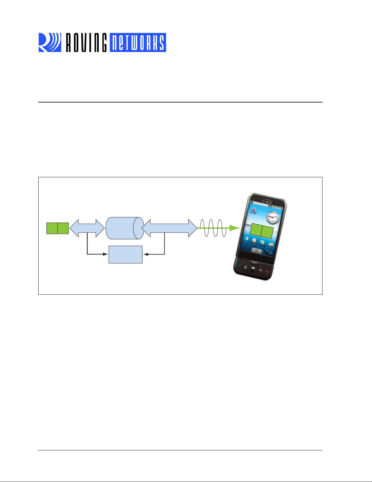
1.3 COMMAND MODE VS. DATA MODE
The Bluetooth module operates in two modes: data mode (default) and command
mode. While in data mode, the module operates as a data pipe. When the module
receives data, it strips the Bluetooth headers and trailers and passes the user data to
the UART port. When data is written to the UART port, the module constructs the Bluetooth packet and sends it out over the Bluetooth wireless connection. Thus, the entire
process of sending/receiving data to the host is transparent to the end microprocessor.
See Figure 1-1.
FIGURE 1-1: DATA & COMMAND MODES
RN-BT-DATA-UG
The default configuration for the Bluetooth module is:
• Bluetooth slave mode
• Bluetooth pin code 1234
• Serial port 115,200 Kbps baud rate, 8 bits, no parity, 1 stop bit
• Serial port flow control disabled
• Low power mode off
You configure the module by putting it into command mode (see “Enter Command
Mode” on page 8) and sending ASCII commands over the UART port or the Bluetooth
link. You reboot the module so that the settings take effect. Once you change the configuration parameters, they persist until you change them or you perform a factory
reset.
There are two ways to configure the Bluetooth module:
• Local configuration using your computer’s serial port
• Via Bluetooth
www.rovingnetworks.com Version 1.0r 3/26/13 page 6
Advanced Information

RN-BT-DATA-UG
You need a terminal emulator to complete the setup.
Note: Use either the TeraTerm (Windows OS) or CoolTerm (Mac OS-X) terminal
emulator program.
1.3.1 Configuring the Module over the UART Port
Connect the module to your computer. You can connect using the RS-232 DB9 port or
via a USB cable. For example, if you are using the RN-41-EK evaluation board, connect it to your computer using a USB cable.
With the Bluetooth module connected and powered on, run a terminal emulator and
open the COM port to which the cable is connected. The terminal emulator’s communication settings should be the default serial port settings:
• Baud rate 115,200 kbps
•8 bits
•No parity
• 1 stop bit
• Hardware flow control enabled
Note: You can use local configuration at any time when the module does NOT
have a Bluetooth connection, as well as under certain conditions. If the
module is in configuration mode and a connection occurs, the module exits
configuration mode and data passes back and forth from the remote module.
Once a connection is made, you can only enter command mode if the boot-up configuration timer has not expired (60 seconds). To remain in configuration mode, set the
configuration timer to 255. See “Configuration Timer Settings” on page 44 for more
information.
Note: If the module is in Auto-Connect Master Mode, you cannot enter command
mode when connected over Bluetooth. See “Operating Modes” on page 10
for more information on the various operating modes.
Refer to “Enter Command Mode” on page 8” for information on entering command
mode from a terminal emulator.
1.3.2 Remote Configuration Using Bluetooth
It is often useful to configure the module remotely over a Bluetooth connection. Before
performing remote configuration using Bluetooth, first pair the Bluetooth module with
your computer. For PCs with Bluetooth capability and running Windows, click Blue-
tooth devices in the system tray at the bottom right of your computer screen. Select
Add a Bluetooth device and follow the on-screen instructions. For Mac OS-X, click
the Bluetooth icon, select Set up Bluetooth device, and follow the on-screen instructions.
Once a connection is made, you can only enter command mode if the boot-up configuration timer has not expired (60 seconds). To remain in configuration mode, set the
configuration timer to 255. See “Configuration Timer Settings” on page 44 for more
information.
www.rovingnetworks.com Version 1.0r 3/26/13 page 7
Advanced Information
RN-BT-DATA-UG
When you are finished configuring, reset the module or send the --- command, which
causes the module to exit configuration mode and allows data to pass normally.
Note: Configuration mode (local or remote) is NEVER enabled when the module
is in auto-mode and is connected over Bluetooth.
1.3.3 Enter Command Mode
To enter command mode, launch a terminal emulator and specify the module’s default
settings. Ta bl e 1 -1 shows the serial port settings.
TABLE 1-1: SERIAL PORT SETTINGS
Setting Value
Port COM port to which you attached the module
Baud rate 115200
Data rate 8 bits
Patiry None
Stop bits 1
Flow control None
Type
$$$ into the terminal emulator to enter command mode.
The module returns the string
CMD, which indicates that your connection and terminal
settings are correct. While in command mode, the module accepts ASCII bytes as commands. When you enter a valid command, the module returns
invalid command and
? for unrecognized commands. Type h <cr> to see a list of com-
AOK. It returns ERR for an
mands.
A quick check to confirm that you are in command mode is to type the
X <cr> command
after entering command mode. This command shows the a summary of the module’s
current settings, such as the Bluetooth name, device class, and serial port settings.
See Figure 1-2.
To return to data mode, type
--- <cr> or reset the module and re-connect.
Note: The module supports a fast data mode. In this mode, the module does not
go into command mode even if it receives $$$. If you do not enter command
mode within the configuration window (60 seconds), the module enters fast
data mode. See “ST,<value>” on page 26 and “Configuration Timer Set-
tings” on page 44 for more information on setting the configuration window.
www.rovingnetworks.com Version 1.0r 3/26/13 page 8
Advanced Information
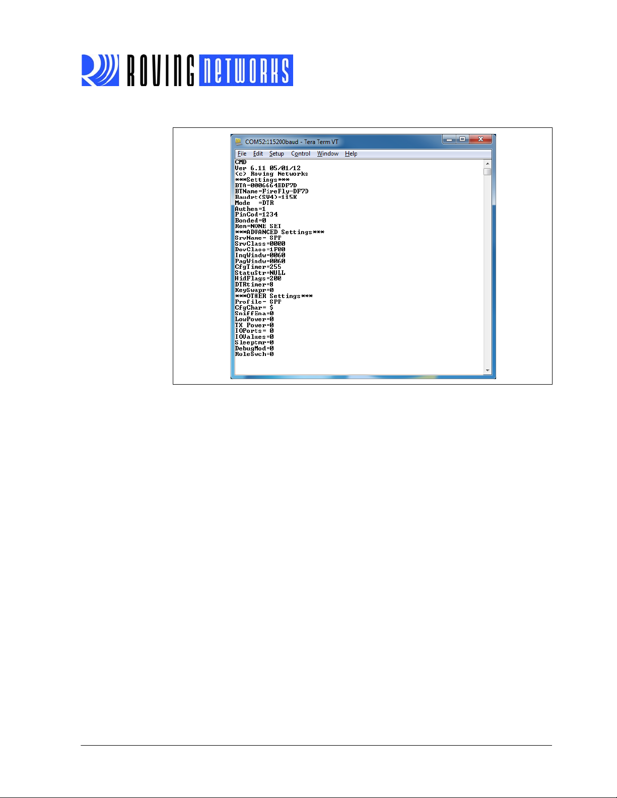
FIGURE 1-2: VIEW CURRENT SETTINGS
RN-BT-DATA-UG
www.rovingnetworks.com Version 1.0r 3/26/13 page 9
Advanced Information
1.4 OPERATING MODES
The Bluetooth module has several operating modes, which you set using the SM command in command mode.
Note: In all master modes, the module cannot be discovered or configured
remotely over Bluetooth.
• Slave Mode (SM,0)—Default mode, in which other Bluetooth devices can discover
and connect to the module. You can also make outbound connections in this
mode.
• Master Mode (SM,1)—In this low-speed connection mode, the module makes
connections when a connect command (
contain the Bluetooth address of the remote device. If a device is not specified,
the module uses the stored remote address. The connection can be broken if the
special break character or string is sent (use the
character). This mode is useful when you want the module to initiate connections
(not receive them). In this mode, the module is NOT discoverable or connectable.
• Trigger Mode (SM,2)—In this low-speed connection mode, the module makes
connections automatically when a character is received on the serial port (UART).
The connection continues as long as characters are received on either end. The
module has a configurable timeout (which you set using the
disconnects the module after the specified number of seconds of inactivity (1 to
255) or a configurable break character is received.
• Auto-Connect Master Mode (SM,3)—In this mode, the module makes connec-
tions automatically on power-up and re-connects when the connection is lost. This
mode can be set by command, or by setting the external dipswitch 3 during power
up (evaluation kits) or by driving GPIO6 high (Bluetooth modules). If an address is
not stored, the module performs an inquiry process and the first device found that
matches the COD is stored. In this mode, high-speed data is passed without being
interpreted; therefore, the connection cannot be broken via commands or software break characters. If a disconnect occurs, the module attempts to re-connect
until successful.
• Auto-Connect DTR Mode (SM,4)—This mode must be set by command. It oper-
ates like Auto-Connect Master Mode, except that you control connection and disconnection with dipswitch 3 (evaluation kits) and GPIO6 (Bluetooth modules).
Turning the dipswitch on or driving GPIO6 high initiates the auto-connect process;
turning the dipswitch off or driving GPIO6 low causes a disconnect.
• Auto-Connect ANY Mode (SM,5)—This mode must be set by command. This
mode operates like Auto-Connect DTR Mode, except that each time the dipswitch
or GPIO is set, an inquiry is performed and the first device found is connected.
The stored address is NOT used, and the address found is never stored.
• Pairing Mode (SM,6)—In this mode, the module attempts to connect with the
remote device matching the store remote address. You set the remote address
using the
SR command.
RN-BT-DATA-UG
C) is received. This command can also
SO command to set the break
ST command) that
www.rovingnetworks.com Version 1.0r 3/26/13 page 10
Advanced Information

RN-BT-DATA-UG
1.5 USING DIPSWITCHES & GPIO PINS FOR CONFIGURATION
The Bluetooth modules have dipswitches (for evaluation kits) or GPIO pins (for modules) that you can use to configure the module. See Tab le 1 - 2.
TABLE 1-2: DIPSWITCH & GPIO SETTINGS
Dipswitch
Function
Factory Reset 1 GPIO4 Off = disabled, on = armed.
Auto Discovery/
Pairing
(Adpaters &
Evaluation
Boards)
2 GPIO3 Off = disabled, on = enabled.
GPIO Pin
(Modules)
Settings (OFF = 0 VDC/ON = 3 VDC)
Set this dipswitch/GPIO pin on power up to arm the reset function. Then
toggle the module off and on three times to reset all settings to the factory defaults (other than the Bluetooth name).
You use these settings in conjunction with dipswitch 3/GPIO6. If
dipswitch 3/GPIO6 are also set, the module performs a device inquiry
scan, searching for a partner device with a special matching class
(0x55AA). Once it finds this device, it stores the address into the remote
address field and auto-connects to the remote device.
If dipswitch 3/GPIO6 are NOT set, the module enters slave mode with
the special matching class and waits for the master to find it. This mode
is usually set once on both ends of a module pair (for instant cable
replacement) and then removed.
Auto-Connect 3 GPIO6 Off = disabled, on = enabled.
This setting is equivalent to Auto-Connect Master Mode in software. The
module connects to the stored address. If dipswitch 2/GPIO3 is also set,
a new discovery/pairing can be made.
If connected via the CFR command, toggling the dipswitch off-on-off terminates the current connection.
Baud Rate 4 GPIO7 Off = stored setting (115 K), on = 9,600.
This setting is used to configure 9,600 or a software selected (default =
115 K) baud rate. If the dipswitch is off, the module uses the stored
baud rate setting. When the dipswitch is on, the baud rate is set to 9,600
regardless of the software setting.
www.rovingnetworks.com Version 1.0r 3/26/13 page 11
Advanced Information

RN-BT-DATA-UG
Ta bl e 1 -3 describes the GPIO pin assignments for Roving Networks Bluetooth hard-
ware. Refer to “GPIO Commands” on page 37 for more information on the commands
you use to configure the GPIO pins.
TABLE 1-3: GPIO ASSIGNMENTS
RN4x, RN4xXV,
GPIO
Firmware 4.77 6.xx 6.11-HID DEMO
GPIO2 – – IN: (B7) power on/off, left arrow, iOS
GPIO3 IN: (dipswitch 2), discovery/auto-pair
read at power up, DCD in DUN and
MDM profile
GPIO4 IN: (dipswitch 1), factory default IN: (dipswitch 1), factory default IN: presentation (B1)
GPIO5 OUT: system status (green LED) OUT: system status (green LED) OUT: system status (green LED)
GPIO6 IN: (dipswitch 3), auto connect read
at power up, DSR in DUN and MDM
profile
GPIO7 IN: (dipswitch 4), baud rate select on
power up, CTS in DUN and MDM
profile
GPIO8 OUT: over the air TX activity (blue
GPIO9 OUT: fire relay A on RD1 – –
GPIO10 – – IN: pull high connect to stored Blue-
GPIO11 – – IN: on power up if high, HID profile is
RN220, RN270,
RN-XV-EK,
RN-XV-RD1/2
RN-4X-EK RN-BT-HID-RD1
keyboard toggle
– IN: (B3) Custom, down arrow
– IN: factory reset (B4)
– IN: (B3), music
–
LED)
tooth address; pull low disconnect if
connected
OUT: (B6), SPP, FAST-FWD
selected AND if bit 9 in HID flag is set
(SH,<value>)
1.6 MAKING A BLUETOOTH CONNECTION
By default, the Bluetooth module acts as a slave and the PC or smartphone is the master. You connect to the Bluetooth module using the Bluetooth device manager, which
varies depending on your smartphone or computer’s operating system. In all cases, the
process is the same:
• Discovery—In the discovery phase, the Bluetooth module broadcasts its name,
profile support, and MAC address. It is ready for other devices to pair with it. Discovery is only availoable in slave mode.
• Pairing—During pairing, the Bluetooth module and the Bluetooth master validate
the pin code. If the pin code validates successfully, they exchange security keys
and a channel hopping pseudo-random sequence. Successful pairing results in
the module and master establishing link keys.
• Connecting—Before connecting, the Bluetooth devices must have paired suc-
cessfully. The master initiates a connection, the master and slave validate the link
keys, and a Bluetooth link is established.
The following sections describe these processes in detail.
www.rovingnetworks.com Version 1.0r 3/26/13 page 12
Advanced Information
RN-BT-DATA-UG
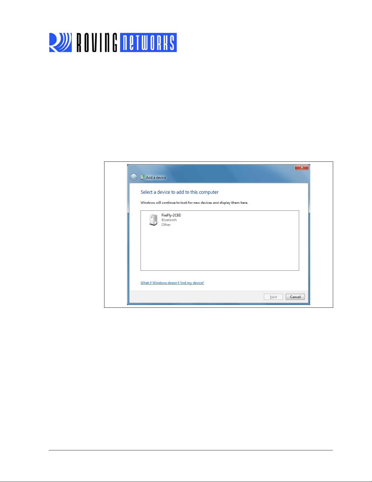
1.6.1 Discovery
When you turn on the Bluetooth module, it is discoverable. For evaluation kits, the
green LED blinks, indicating that it is discoverable. Open your PC’s Bluetooth device
manager and choose to add a new device. The Bluetooth device manager’s icon is
located in the bottom right corner of your screen in the taskbar for Windows and in the
upper right corner for Mac OS-X. The Bluetooth device manager displays a list of discoverable Bluetooth devices (see Figure 1-3). The Bluetooth module displays as Serial
Port Profile (SPP) Service FireFly-ABCD, where FireFly is the type of Roving Networks module and ABCD is the last four nibbles of the Bluetooth MAC address. (You
can change the local device name).
FIGURE 1-3: DISCOVER THE BLUETOOTH MODULE
1.6.2 Pairing
To pair with the module, double-click the module’s name (i.e., FireFly-XXXX) in the list.
The firmware automatically stores up to 8 pairings from remote hosts in a first in, first
out fashion.
Choose to enter the module’s pairing code (see Figure 1-4) and enter the default pin
code, 1234. When the Bluetooth device manager completes pairing, it issues a mes-
sage that the Bluetooth device is installed on COMX where COMX is unique to your
computer. In some cases, the Bluetooth device manager creates two COM ports; in this
situation, only use the COM port labeled “outgoing.”
www.rovingnetworks.com Version 1.0r 3/26/13 page 13
Advanced Information
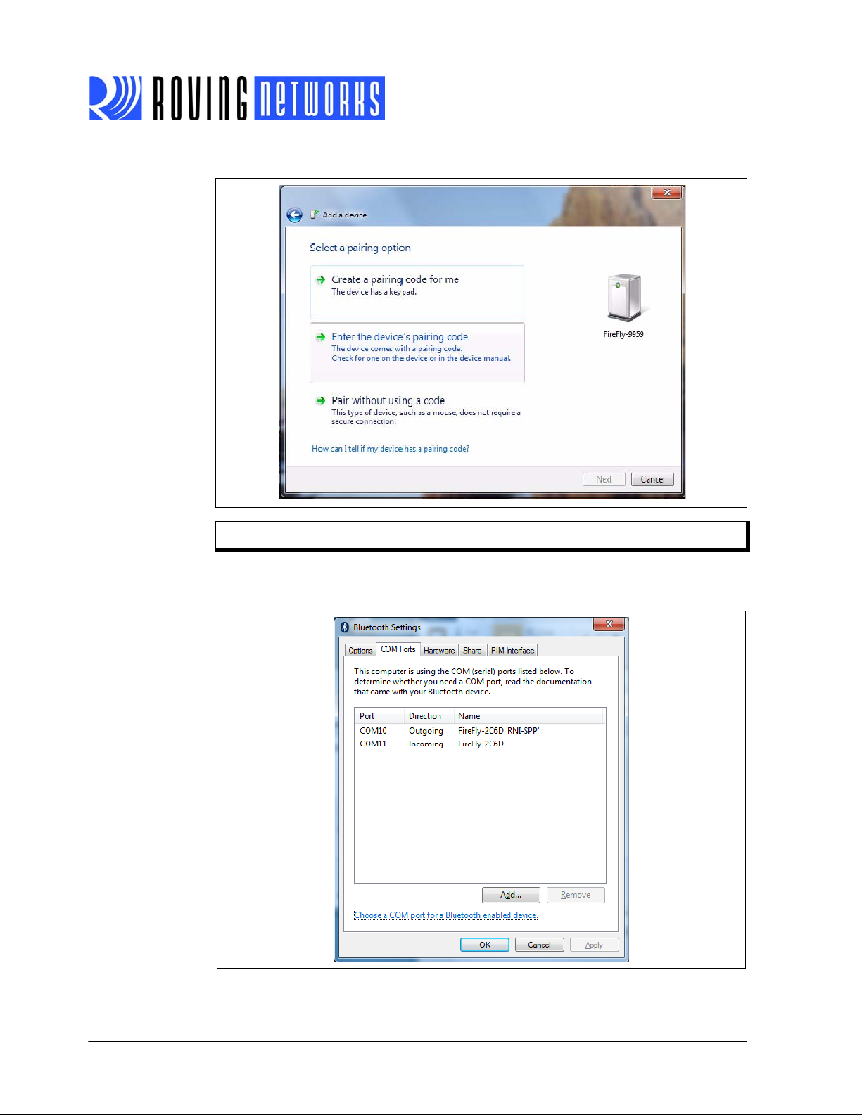
FIGURE 1-4: PAIR WITH THE BLUETOOTH MODULE
RN-BT-DATA-UG
Note: You only need to pair with the module once.
Figure 1-5 shows example COM port settings.
FIGURE 1-5: BLUETOOTH COM PORT SETTINGS
www.rovingnetworks.com Version 1.0r 3/26/13 page 14
Advanced Information

RN-BT-DATA-UG
If the remote Bluetooth device does not require authentication, a connection can occur
without the pairing process. However the Bluetooth specification requires that if either
device involved in the pairing process requires authentication, the other device must
participate to ensure a secure link. Roving Networks modules default to an open mode,
such that the module does NOT require authentication. However, most PCs require
authentication. See “Security Modes” on page 17 for more information on using pass
keys.
Once connected, the module is in data mode allowing data to flow in both directions as
if the serial port were locally attached to the PC. For configuration, the module must be
in command mode. See “Enter Command Mode” on page 8 for more information.
Note: Only one client can connect to a slave module at a time. As a master, the
module can make multiple connections, but only in a point-to-point, serialized fashion. Roving Networks modules do not currently support multi-point
master mode.
1.6.2.1 PAIRING WITH A COMPUTER OR SMART PHONE
The module may use simple secure pairing (SSP) if it is attempting to pair with devices
that support the Bluetooth specification version 2.1 + EDR. SSP does not require the
user to remember the pin code, but it asks to confirm the 6-digit number if the device
has a display capability.
1.6.3 Connecting
In most cases, you connect from another device to the module as an outgoing Bluetooth connection. You can also make an incoming connection in which the evaluation
board initiates the connection to the remote device.
1.0.0.1 Outgoing Connections
To establish an outgoing Bluetooth connection from a PC to the module, open the module’s outgoing COM port from your application or a terminal emulator. The module
remains connected until you close the COM port or remove power from the board.
Once connected, the module is in data mode allowing data to flow in both directions.
For configuration, the module must be in command mode. See “Enter Command
Mode” on page 8 for more information.
Note: Only one client can connect to a slave module at a time. As a master, the
module can make multiple connections, but only in a point-to-point, serialized fashion. Roving Networks modules do not currently support multi-point
master mode.
1.0.0.2 Incoming Connections
For an incoming connection you use the port specified in your Bluetooth settings as
incoming (refer back to Figure 1-3). In incoming connections, the PC or host listens for
an incoming connection from the remote Bluetooth device, in this case the module.
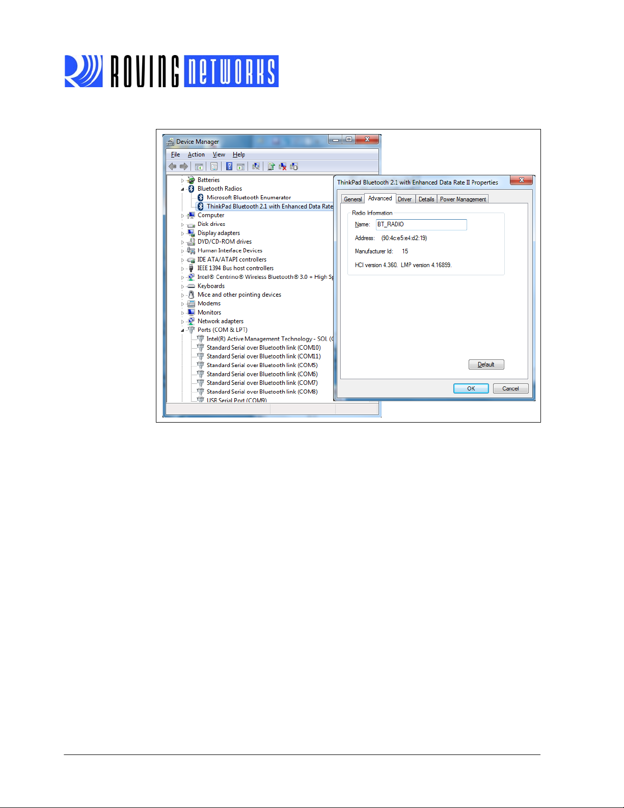
Perform the following steps to make in incoming connection.
1. You need the MAC address of the PC’s Bluetooth radio to connect from the module to the host PC. Open the PC’s Bluetooth advanced settings to find the MAC
address. See Figure 1-6.
www.rovingnetworks.com Version 1.0r 3/26/13 page 15
Advanced Information
RN-BT-DATA-UG
FIGURE 1-6: PC’S BLUETOOTH RADIO MAC ADDRESS
2. Pair your module with the PC as described in “Pairing” on page 13.
3. Open a terminal (called terminal A in this example) and connect it to the module.
You can run this terminal on the host PC or another computer.
4. Open a second terminal (called terminal B in this example) on the host PC to listen for the incoming Bluetooth connection using the incoming COM port number.
5. Type
C,<MAC address> <cr> in terminal A to establish an SPP connection to the
host PC. See Figure 1-7 for an example connection.
6. Try the following commands:
•
$$$ to enter command mode
•
SO,% to enable status message to see connect/disconnect conditions
•
R,1 to reboot
•
$$$ to re-enter command mode
•
+ to enable local echo
•
C,<MAC address> to attempt a connection with remote device
Characters you type in terminal B are sent over Bluetooth to the host PC and
appear in terminal A. Any characters entered in terminal A are transmitted to terminal B.
7. To kill the connection, type the
k,1 <cr> command in terminal B.
www.rovingnetworks.com Version 1.0r 3/26/13 page 16
Advanced Information
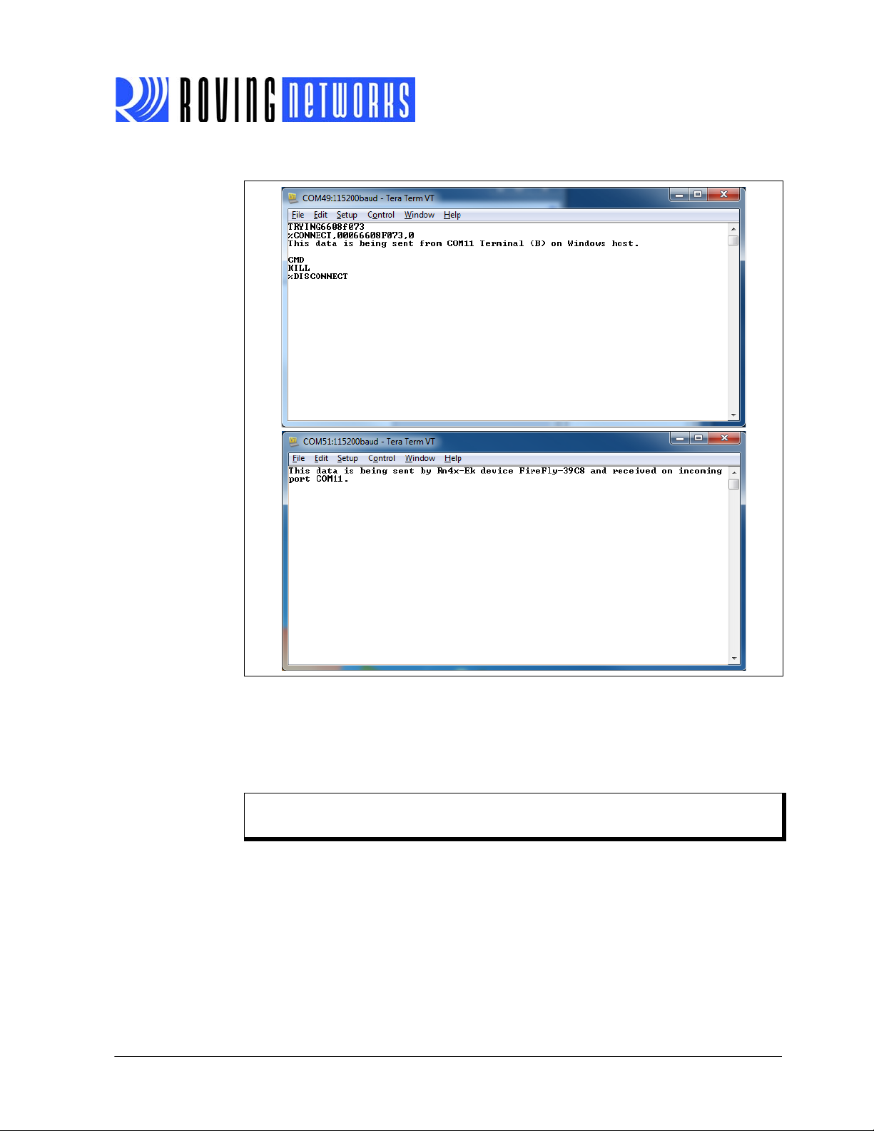
FIGURE 1-7: TERMINALS A & B
RN-BT-DATA-UG
1.6.4 Security Modes
The Bluetooth module supports authentication. If the local or remote Bluetooth device
has authentication enabled, a pin code is required the first time a connection is
attempted. The pin code is a series of numbers or characters from 1 to 16 characters
in length.
Note: The default pin code for Roving Networks Bluetooth modules is 1234. The
RN-41-EK and RN-42-EK evaluation boards do not require a pin code.
After you enter the pin code, the Bluetooth devices compare them. If they match, a link
key is generated and stored. Usually, but not always, the remote device stores the link
key. For subsequent connections, the devices compare link keys. If they are correct,
you do not need to re-enter the pin code.
www.rovingnetworks.com Version 1.0r 3/26/13 page 17
Advanced Information

RN-BT-DATA-UG
If the remote device is a PC or PDA, the user generally is prompted to enter this pin
code. To remove the stored link key on the remote device, you typically “unpair” or
remove the device from the Bluetooth manager. You can change the pin code to
remove the link key on the Bluetooth module, forcing a new pin code exchange to occur
upon subsequent connection attempts.
Note: Only one master can connect to the Bluetooth module at a time.
www.rovingnetworks.com Version 1.0r 3/26/13 page 18
Advanced Information
RN-BT-DATA-UG
Chapter 2. Command Reference
Roving Networks Bluetooth modules support a variety of commands for configuration.
This section describes these commands in detail and provides examples.
2.1 COMMAND SYNTAX
To issue commands to the module, you send a keyword followed by optional parameters.
• All commands are one or two characters and can be upper or lower case.
• Delimit command arguments with a comma.
• Commands use decimal input, except where noted.
• Text data, such as the Bluetooth name and pin code, is case sensitive.
• All commands only take effect AFTER reboot, except where noted.
There are five general command categories, as shown in Table 2-1.
TABLE 2-1: COMMAND TYPES
Command Type Description
Set commands Store information to flash memory. Changes take effect after a power cycle or reboot.
Get commands Retrieve and display the stored information.
Change commands Temporarily change the value of various settings such as serial baud rate, parity, etc.
Action commands Perform actions such as inquiries, connecting, etc.
GPIO commands Configure and manipulate the GPIO signals.
2.2 SET COMMANDS
The set commands specify configuration settings and take effect after power cycling or
rebooting.
2.2.1 S7,<flag>
This command enables/disables 7-bit data mode, where <flag> is shown in Tab le 2 - 2.
TABLE 2-2: 7-BIT DATA MODE VALUES
Default: 0
Example:
2.2.2 SA,<value>
The set authentication command forces authentication when a remote device attempts
to connect, where <value> is one of the values shown in Table 2-3. Regardless of this
setting, if a remote device forces authentication, this device responds with the stored
Flag Description
0 Disable.
1 Enable.
S7,1 // Enable 7-bit data mode
www.rovingnetworks.com Version 1.0r 3/26/13 page 19
Advanced Information
RN-BT-DATA-UG
pin code. Once a remote device has exchanged pin codes with this device, a link key
is stored for future use. The device stores up to 8 keys automatically and permanently
in flash memory, in a first in, first out fashion.
TABLE 2-3: SET AUTHENTICATION VALUES
Value Description
0 Open mode. With this mode, the module uses Bluetooth version 2.0 with NO encryption (open mode). This
mode is useful for legacy devices that do not need security. This mode is the same as in firmware version 4.77.
1 SSP keyboard I/O mode (default). If this option is set, the remote host receives a prompt; reply yes to pair.
For Android devices, the user is prompted with a 6-digit code and is asked to verify that the code matches
on the module. The module always responds yes. Because the module cannot display a code, simply
press OK or Yes on the remote device to authenticate.
2 SSP “just works” mode. This mode works with iOS device and newer PCs. You can use this mode with
Droid devices if the application connects using unsecure mode (which was the default on Droid version
3.3). This mode also works with new PC stacks.
4 Pin code. Forces pin code mode authentication (Bluetooth version 2.0), which requires the host device to
enter a pin code that matches the stored pin code. The functionality is similar to firmware version 4.77.
Note: Modes 0 and 4 are legacy modes that do not support SSP (Bluetooth ver-
sion 2.0).
Default: 1
Example:
SA,1 // Enable authentication
2.2.3 SB,<value>
When you issue the set break command, the device sends a break signal immediately
where <value> is the length of the break signal in milliseconds as shown in Tab le 2 - 4.
The break signal on the UART TX pulls the line low.
TABLE 2-4: SET BREAK VALUES
Value Break Length (ms)
137
2 18.5
312
49
57
66
Default: N/A
Example:
SB,1 // Send a break signal of 37 ms
2.2.4 SC,<value>
This command sets the service class field in the class of device (COD). The service
class consists of the most significant 11 bits in the COD. This command sets the MSW
to create the 24-bit device class number. The inquiring device interprets the service
class to determine the service. A complete listing of available Bluetooth service classes
is referenced on the Bluetooth SIG web site.
www.rovingnetworks.com Version 1.0r 3/26/13 page 20
Advanced Information

RN-BT-DATA-UG
Default: 0000
Example:
2.2.5 SD,<value>
This command sets the class of device (COD) LSW. The COD is a 24-bit number that
is made up of the device class with major 8 bit and minor in a 16-bit word. This command is used with the service class command.
Default: 1F00
Example:
2.2.6 SE,<value>
In firmware versions 5.40, 6.10, and above, this command sets the UUID for outbound
connections. Roving Networks bluetooth modules use the standard SPP UUID of
0x1101. Encryption is always enabled in firmware versions 5.40 and higher.
SC,0002 // Set service class to 0002
SD,8040
To set the COD to 0x1F0123, use the following commands:
SC,001F
SD,0123
2.2.6.1 FIRMWARE VERSION 5.40 & HIGHER
The UUID setting is useful for Android-based applications so that the application can
uniquely determine the remote device. Android applications require a 128-bit UUID.
00001101-0000-1000-8000-00805F9B34FB is the 16-bit UMUID for the serial port profile (0x1101) when promoted to a 128-bit UUID. Android application developers are
expected to use this 128-bit UUID for SPP.
This feature applies to SPP connect back only, which is used primarily for Android
devices. With this feature, you can set a custom UUID for connecting back. Android
phones run an audio gateway that always attempts to grab a connection when it comes
in from a remote Bluetooth device such as the Roving Networks module. With the
SE
command, you can register a custom UUID, which ensures that ONLY your application
obtains the connection when it comes in.
The default SSP UUID is 35111C0000110100001000800000805F9B34FB.
You can modify a subset of the UUID; the bytes are changed from left to right. For
example, if the UUID is:
35111C0000110100001000800000805F9B34FB
Typing the command
SE,ABCD<cr> changes the first 2 bytes resulting in:
ABCD1C0000110100001000800000805F9B34FB
The command has three short forms:
SE,S // Loads the default SPP UUID
SE,I // Loads the iPhone UUID
SE,C // Loads the custom UUID (appropriate for testing or custom use)
spp_uuid[19] =
{0x35,0x11,0x1C,0x00,0x00,0x11,0x01,0x00,0x00,0x10,0x00,0x80,0x00,0x00,0x80,0
x5F,0x9B,0x34,0xFB };
www.rovingnetworks.com Version 1.0r 3/26/13 page 21
Advanced Information
RN-BT-DATA-UG
iphone_uuid[19] =
{0x35,0x11,0x1C,0x00,0x00,0x00,0x00,0xDE,0xCA,0xFA,0xDE,0xDE,0xCA,0xDE,0x
AF,0xDE,0xCA,0xCA,0xFE };
Where FE is the iPhone UUID and FF is a local UUID.
droid_uuid[19] =
{0x35,0x11,0x1C,0xEE,0x28,0x6E,0xA0,0x00,0x01,0x11,0xE1,0xBE,0x50,0x08,0x00,
0x20,0x0C,0x9A,0x66 };
Default: 0x1101
Example:
2.2.6.2 FIRMWARE PRIOR TO VERSION 5.40
For firmware prior to version 5.40, the SE command enables and disables encryp-
tion.The <flag> value determines whether or not encryption is enabled as shown in
Ta bl e 2 -4 .
TABLE 2-5: SET ENCRYPTION ENABLE
SE,0000110100001000800000805F9B34FB // Set the UUID for Droid
Flag Description
0 Disable.
1 Enable.
2.2.7 SF,1
This command restores the device to the factory defaults.
Example: SF,1 // Restore factory defaults
2.2.8 SH,<value>
The HID flag register is a bit-mapped register that is configured while in command
mode. To set the register, use the SH, <value> command, where <value> is a 4-char-
acter hex word. The GH command returns the current value of the register. The default
factory setting is 0000, which corresponds to a keyboard.
Note: This command is only available for use in the HID profile. Refer to Chapter
5. “HID Profile” for more information on using the HID profile.
Ta bl e 2 -6 shows the HID flag register bits; currently only the lower 9 bits are defined.
See “HID Flag Register” on page 61 for more information on setting these bits.
TABLE 2-6: HID FLAG REGISTER BITS
9 8 7..4 3 2..0
Force HID mode if
GPIO11 is high on
power-up.
Toggle virtual keyboard on iOS when
first connected.
Descriptor type:
0000 = Keyboard
0001 = Game Pad
0010 = Mouse
0011 = COMBO
0100 = JOYSTICK
1XXX = Reserved
Send output reports
over UART.
Indicates number of
paired devices to which
the module can reconnect.
Default: 0200
Example:
www.rovingnetworks.com Version 1.0r 3/26/13 page 22
SH,0220 // Set the device as a mouse
Advanced Information

RN-BT-DATA-UG
2.2.9 SI,<hex value>
The inquiry scan window command sets the length of time the device spends enabling
an inquiry scan (discoverability). The minimum value is 0x0012, corresponding to about
a 1% duty cycle.
The page scan interval is fixed at 0x1000. The default window is 0x0100. The maximum
value is 0x800. Set this parameter to 0x0000 to disable inquiry scanning and render the
device undiscoverable. If the host has already paired, the inquiry scan is not used.
Note: When pairing with Android devices, increasing this value makes pairing
more reliable.
Default: 0100
Example:
2.2.10 SJ,<hex value>
The page scan window command sets the amount of time the device spends enabling
page scanning (connectability). The minimum value is 0x0012, which corresponds to
about a 1% duty cycle. The page scan interval is fixed at 0x1000. The default window
is 0x0100. The maximum value is 0x800. Set this option to 0x0000 to disable page
scanning and render the device non-connectable.
SI,0200 // Set inquiry scan window to 0x0200
Note: When pairing with Android devices, increasing this value makes pairing
more reliable.
Default: 0100
Example:
SJ,0200 // Set the page scan window to 0x0200
2.2.11 SL,<char>
This command sets the UART parity, where <char> is a character shown in Ta ble 2- 7.
TABLE 2-7: UART PARITY VALUES
Value Description
E Even.
OOdd.
N None.
Default: N
Example:
SL,E // Set parity to even
www.rovingnetworks.com Version 1.0r 3/26/13 page 23
Advanced Information

RN-BT-DATA-UG
2.2.12 SM,<value>
This command sets the mode, where <value> is a decimal number as shown in
Ta bl e 2 -8 .
TABLE 2-8: MODE VALUES
Value Description
0 Slave Mode.
1 Master Mode.
2 Trigger Mode.
3 Auto-Connect Master Mode.
4 Auto-Connect DTR Mode.
5 Auto-Connect Any Mode.
6 Pairing Mode.
Default: 04
Example:
2.2.13 SN,<string>
SM,0 // Set the mode to slave
This command sets the device name, where <string> is up to 20 alphanumeric charac-
ters.
Default: N/A
Example:
SN,MyDevice // Set the device name to “MyDevice”
2.2.14 SO,<string>
This command sets the extended status string, where <string> is up to 8 alphanumeric
characters. Setting this string to from 1 to 8 characters permits status messages to be
sent to the local serial port. When you set this parameter, two status messages are
sent:
• When a Bluetooth connection is established, the device sends the string
<string>
• When disconnecting, the device sends the string <string>
This parameter is useful when connecting to equipment or hardware. For example,
when the device is connected to a printer, the printer can examine an escape
sequence. If <string> is set to
CONNECT
modes, the first character of this string is used as the break connection character.
Default: Disabled
Example:
CONNECT.
DISCONNECT.
ESC%, the printer can parse ESC%CONNECT and ESC%DIS-
messages without interfering with normal print jobs. In trigger or master
SO,ESC% // Set escape sequence
SO,<space> // Disables the extended status string
www.rovingnetworks.com Version 1.0r 3/26/13 page 24
Advanced Information

RN-BT-DATA-UG
2.2.15 SP,<string>
This command sets the security pin code, where <string> is up to 20 alphanumeric
characters. Each time the device pairs successfully, it saves the Bluetooth address.
The device can store up to eight addresses on a first in first out basis. Using this command also erases all stored pairings. You can use the same value that is already set.
You cannot erase the pin code, however, you can overwrite the default pin code.
Default: 1234
Example:
2.2.16 SQ,<mask>
This command is for special configuration settings, where <mask> is a decimal number
as shown in Ta bl e 2 -9 .
TABLE 2-9: SPECIAL CONFIGURATION SETTINGS VALUES
Mask Description
0 Default. The device does not use any special configuration.
4 With this option set, the device does not read the GPIO3 and GPIO6 pin values on
8 Disables discoverability at power up. Clear this setting with SQ,0. Use the W or Q,1
16 This option configures the firmware to optimize for low latency data transfers rather
128 This option causes the device to reboot after disconnect.
256 This option sets 2 stop bit mode on the UART.
SP,0123 // Set pin code to “0123”
power-up. This command is used when configuring GPIO3 and GPIO6 for a function
other than the default configuration. See “GPIO Commands” on page 37.
commands to enable discovery at runtime.
than throughput.
Note: If the module is unable to connect to the Bluetooth device for 15 to 30 sec-
onds after disconnecting, try clearing the
SQ, bit (i.e., use SQ,0).
Default: 0 // Do not use special configuration
Example:
SQ,128 // Reboot after disconnect
2.2.17 SR,<hex value>
This command stores the remote address, where <hex value> is 12 hexadecimal digits
(6 bytes) with no spaces or characters between digits. Additionally, this command takes
two special characters for the address parameter:
•
SR,Z erases any stored addresses.
•
SR,I writes the last address observed using the inquiry command. This command
can be helpful when you only have one other device in range.
Note: In firmware version 6.12, you must type the SR,Z command in uppercase
characters. If you type the command in lowercase characters, the module
returns
Default: N/A
Example:
www.rovingnetworks.com Version 1.0r 3/26/13 page 25
SR,00A053112233 // Set the remote Bluetooth address to
ERR.
// 00A053112233
Advanced Information

RN-BT-DATA-UG
2.2.18 SS,<string>
This command sets the service name, where <string> is from 1 to 20 alphanumeric
characters. This command is not supported in firmware version 6.x.
Default: SPP
Example:
2.2.19 ST,<value>
This command sets the remote configuration timer, where <value> is a decimal number
from 0 to 255 representing the time window (in seconds) to allow remote configuration
over Bluetooth after power up in Slave Mode. In all Master modes, the remote configuration timer is set to 0 (no remote configuration). In Trigger Master Mode, the configuration timer is used as an idle timer to break the connection after time expires with no
characters received.
The module supports a fast data mode. In this mode, the module does not go into command mode even if it receives $$$. If you do not enter command mode within the configuration window set by the configuration timer, the module enters fast data mode.
This command has the special modes shown in Tab le 2 - 10 .
TABLE 2-10: CONFIGURAION TIMER SETTINGS
Value (Decimal) Description
SS,SerialPort // Service name set to “SerialPort”
0 No remote configuration. No local configuration when connected.
1 - 252 Time in seconds from power up to allow configuration.
253 Continous configuration, local only.
254 Continous configuration, remote only.
255 Continous configuration, local and remote.
Default: 60
Example:
ST,0 // Disable remote configuration
ST,255 // Enable remote configuration forever
2.2.20 SU,<value>
The set UART baud rate command sets the baud rate where <value> is 1200, 2400,
4800, 9600, 19.2, 28.8, 38.4, 57.6, 115K, 230K, 460K, or 921K. You only need to specify the first 2 characters of the desired baud rate.
Note: After a factory reset, the device returns 0 when you issue the GU command,
however, the module communicates at 115K.
Default: 115,200
Example:
SU,57 // Set the baud rate to 57,600
2.2.21 SW,<value>
This command enables low-power Sniff mode, which allows extremely low-power operation. In the mode, the device goes into a deep sleep and wakes up every 625 μs x
<value> to send/receive data. For example, the
625 μs = 50 ms) causes the module to enter low-power sleep and wake once every 50
ms to check for RF activity.
www.rovingnetworks.com Version 1.0r 3/26/13 page 26
Advanced Information
SW,0050 setting (0x50 = 80, 80 x

RN-BT-DATA-UG
This setting is useful for applications in which the device is connected and sending
data. Data is not lost; however, it may have a delay. See “Sniff Mode” on page 42 for
more details on this mode and managing power.
Default: 0000 // Disable Sniff mode
Example:
2.2.22 SX,<flag>
The bonding command determines which connections the device accepts, where
<flag> is a value shown in Ta bl e 2 -11 . If bonding is enabled, the device only accepts
connections from the device that matches the stored Bluetooth address register. You
can set the stored address register with the
device pairing.
TABLE 2-11: BONDING VALUES
SW,0050 // Enable Sniff mode with interval time of
// 50 ms
SR command or it can be set upon the first
Flag Description
0 Disable.
1 Enable.
Default: 0
Example:
SX,1 // Enable bonding
2.2.23 SY,<hex value>
This command sets the module’s transmit power, where <hex value> represents the
desired power setting.
In August 2012, Roving Networks changed the power setting hex values. The new
power setting:
• Uses the desired power value instead of an arbitrary value
• Shifts the power range up to use the highest transmit power
• Provides more evenly spaced linear power values.
Ta bl e 2 -1 2 describes the
TABLE 2-12: POWER SETTINGS (AUGUST 2012 AND LATER)
Hex Power (dBM)
0010 16
000C 12
0008 8
0004 4
0000 0
FFFC -4
FFF8 -8
FFF4 -12
SY, power settings for August 2012 and later.
www.rovingnetworks.com Version 1.0r 3/26/13 page 27
Advanced Information

RN-BT-DATA-UG
Ta bl e 2 -1 3 describes the power settings for the SY, command prior to August 2012.
TABLE 2-13: POWER TABLE (BEFORE AUGUST 2012)
Hex Power (dBM)
0004 12
0000 6
FFFC 2
FFF8 0
FFF4 -5
FFF0 -10
FFE8 -20
Default: 16
Example:
To determine which power settings your module uses, you restore your module to the
factory defaults and then view the power setting. The factory default is for the module
to use maximum power. Therefore, if the power setting displays as 10 hex (16 decimal),
the module uses the new power settings. If the power displays as 4 hex (12 decimal),
the module uses the old power settings.
To find the power setting:
1. Type
2. Type
3. Type
4. Type
5. Type
SY,000C // Set the power to 12 dBM
$$$ in a console to put the module into command mode.
SF,1 <cr> to restore the factory defaults.
R,1 <cr> to reboot the module.
$$$ to go into command mode.
GY <cr> to view the power setting.
2.2.24 SZ,<value>
You use this command to specify non-standard raw baud rates, where <value> is a
decimal number based on the formula <value> = baud rate x 0.004096. This setting
takes effect after rebooting.
Default: N/A
Example:
www.rovingnetworks.com Version 1.0r 3/26/13 page 28
SZ,39 // Set the baud rate to 9,521.48
Advanced Information

RN-BT-DATA-UG
2.2.25 S~,<value>
This command sets the profile, where <value> is shown in Ta bl e 2 -1 4 . See “Profile Set-
tings & Features” on page 46 for more details on profiles.
TABLE 2-14: PROFILE VALUES
Value Profile Comments
0 SPP Default, no modem control.
1 DUN-DCE Slave or gateway. Note 1
2 DUN-DTE Master or client. Note 1
3 MDM SPP With modem control signals. Note 1, Note 2
4 SPP and DUN-DCE Multi-profile. Note 1
5 APL Apple (iAP) profile. Refer to the iAP Bluetooth Evaluation Kit for
Developing Accessories Compatible with iOS Devices User
Manual for more information on using this profile.
6 HID HID profile. To use the Bluetooth HID profile, the device must
be running a special firmware version. See Chapter 5. “HID
Profile” for more information.
Note 1: Refer to “Profile Settings & Features” on page 46 for information on
modem control signals and GPIO assignments.
2: In this mode, GPIO11 is reserved for RTS.
Default: 0
Example:
S~,0 // Set profile to SPP
2.2.26 S-,<string>
This command sets the serialized friendly name of the device, where <string> is up to
15 alphanumeric characters. This command automatically appends the last 2 bytes of
the Bluetooth MAC address to the name, which is useful for generating a custom name
with unique numbering.
Default: N/A
Example:
S-,MyDevice // Set name to “MyDevice-ABCD”
www.rovingnetworks.com Version 1.0r 3/26/13 page 29
Advanced Information

RN-BT-DATA-UG
2.2.27 S?,<flag>
The role switch command enables and disables the role switch, where <flag> is shown
in Tab l e 2- 15 . If the switch is set, when a slave mode device receives an incoming connection, the device tries to force a role switch, allowing the slave to become the master.
This option is useful in situations where the local device sends high-speed data up to
the remote host, and can result in better performance. However, this setting may create
a situation in which the connecting host cannot make additional outbound connections
(multi-point) while connected to this device.
TABLE 2-15: ROLE SWITCH VALUES
Flag Description
0 Disable.
1 Enable.
Default: 0
Example:
2.2.28 S$,<char>
S?,1 // Enable role switch
This command sets the configuration detect character string, where <char> is a single
character. This setting allows you to change the default string to go into command
mode (
device to using
$$$) to some other character string. Restoring the factory defaults returns the
$$$.
Default: $
Example
S$,# // Set ### as string to go into command
// mode
2.2.29 S|,<value>
The low-power connect mode command disables the Bluetooth radio and LED timers
while not connected, where <value> is a 4-digit number made up of two 1-byte inter-
vals. The first interval is the off period and the second the on period. Both are in hex
seconds (not decimal). The maximum value for either interval is 20 seconds. The
default is 0000, which indicates always actively waiting for a connection.
When this option is set, the module cycles between active (discoverable and connectable) and low-power deep sleep. This setting can save considerable power when the
module is waiting for a long time without a connection. The trade off is additional
latency when connecting or pairing.
Default: 0000
Example:
S|,2001 // Cycle on for 1 s and OFF for 32 s
// (hex 20 = decimal 32)
www.rovingnetworks.com Version 1.0r 3/26/13 page 30
Advanced Information

2.3 GET COMMANDS
The get commands retrieve and display the device’s stored information. These commands do not have a keyword or character and do not take any parameters, except as
noted.
2.3.1 D
This command displays basic settings such as the address, name, UART settings,
security, pin code, bonding, and remote address.
Example:
2.3.2 E
This command displays the device’s extended settings such as the service name, service class, device class, and configuration timer.
Example:
2.3.3 GB
RN-BT-DATA-UG
D // Display basic settings
E // Display extended settings
This command returns the device’s Bluetooth address.
Example:
GB // Display the device’s Bluetooth address
2.3.4 GF
This command returns the Bluetooth address of the currently connected device. This
command can give a different result than the
GR command, which is the stored remote
address for re-connecting.
Example:
GF // Show Bluetooth address of currently
// connected device
2.3.5 GK
This command returns the device’s current connection status. 1,0,0 indicates the
device is connected; 0,0,0 indicates that it is not connected.
Note: If diagnostic messages are enabled (using the
device is not connected,
NO_AUTH_CHIP is displayed on the UART and the
module returns the error code 8 when you issue the
Example:
GK // Show the current connection status
SO,% command) and the
GK command.
2.3.6 GR
This command shows the remote address.
Example:
GR // Display remote address
2.3.7 G&
This command returns a hex byte containing the value of the GPIO pins.
Example:
www.rovingnetworks.com Version 1.0r 3/26/13 page 31
G& // Show the GPIO pin values.
Advanced Information

2.3.8 G<char>
This command displays the stored settings for a set command, where <char> is a set
command name.
Example:
GS // Return 1 or 0 depending on the security
2.4 CHANGE & ACTION COMMANDS
Change commands temporarily change the value of various settings such as serial
baud rate, parity, etc. Action commands perform actions such as inquiries, connecting,
and entering/exiting command mode.
2.4.1 $$$
This command causes the device to enter command mode, displaying CMD. The device
passes characters as data until it sees this exact sequence. If the device sees any
bytes before or after the
enter command mode and these bytes are passed through.
You can change the character string used to enter command mode with the
mand.
Example:
$$$ // Enter command mode
$$$ characters in a 1 second window, the device does not
RN-BT-DATA-UG
// value
S$ com-
2.4.2 ---
This command causes the device to exit command mode, displaying END.
Example:
--- // Exit command mode
2.4.3 +
This command toggles the local echo on and off. If you send the + command in command mode, all typed characters are echoed to the output. Typing
+ a second time
turns local echo off.
Default: Off
Example:
+ // Turn local echo on
2.4.4 &
This command returns the evaluation kit’s dipswitch values or GPIO3, 4, 6, 7 values on
other modules.
Example:
& // Display dipswitch or GPIO values
2.4.5 C
This command causes the device to attempt to connect to the stored remote address.
Example:
C // Connect to stored remote address
www.rovingnetworks.com Version 1.0r 3/26/13 page 32
Advanced Information

RN-BT-DATA-UG
2.4.6 C,<address>
This command causes the device to connect to a remote address, where <address> is
specified in hex format. The address is also stored as the remote address.
Example:
2.4.7 CF,<address>
This command causes the device to connect to <address> and immediately go into fast
data mode.
Note: You cannot enter command mode while connected using this command.
C,00A053112233 // Connect to the Bluetooth address
// 00A053112233
However, GPIO6 can still be used to disconnect. Therefore, you should
hold GPIO6 high before sending this command because if GPIO6 goes low,
the device disconnects.
Example:
CF,00A053112233 // Connect to 00A053112233 in fast data
// mode
2.4.8 CFI
This command causes the device to connect and immediately go into fast data mode
using the last address found with the inquiry command.
Note: You cannot enter command mode while connected using this command.
However, GPIO6 can still be used to disconnect. Therefore, you should
hold GPIO6 high before sending this command because if GPIO6 goes low,
the device disconnects.
Example:
CFI // Connect to last found address in fast
// data mode
2.4.9 CFR
This command causes the device to connect and immediately go into fast data mode
using the stored remote address. This command is similar to the
bypasses the configuration timer.
Note: You cannot enter command mode while connected using this command.
However, GPIO6 can still be used to disconnect. Therefore, you should
hold GPIO6 high before sending this command because if GPIO6 goes low,
the device disconnects.
C command, except it
2.4.10 CT,<address>,<value>
This command uses a timer to control the connection duration, where <address> is the
connection address (required) and <value> is the length of the timer in ¼ seconds up
to 255 (optional). For example, a <value> of 255 is 64 seconds.
The device does not use or store a remote address. The device automatically disconnects after 7 seconds if no data is seen from the UART or over Bluetooth. You can use
the optional timer <value> to change the timer length.
www.rovingnetworks.com Version 1.0r 3/26/13 page 33
Advanced Information

RN-BT-DATA-UG
Example: CT,00A053112233 // Connect to 00A053112233 and
// disconnect after 7 seconds if
// no data is seen from UART or Bluetooth
CT,00A053112233,120 // Connect to 00A053112233 and
// disconnect after 30 seconds if
// no data is seen from UART or Bluetooth
2.4.11 F,1
This command ends configuration immediately and puts the device into fast data mode.
Example:
2.4.12 H
The help command displays a list of commands and their basic syntax.
Example:
2.4.13 I,<value 1>,<value 2>
This command performs an inquiry scan, where <valu e 1> is the scan time in seconds
and <value 2> is the optional COD of the device class for which you are scanning. The
default time is 10 seconds, and the maximum is 48. If <value 2> is unused or set to 0,
the device looks for all device classes. When entering a COD, you must provide all six
characters, e.g., you would enter 0040F0 for COD 0x40F0. The scan returns a maximum of 9 devices. As devices are found, they are displayed in the format:
<Bluetooth address>,< Bluetooth name>,<COD>00A053000123,MySerial-
Port,72010C
Default: 10 seconds, no COD
Example:
F,1 // Leave command mode and enter fast
// data mode
H // Display help
I,20,0040F0 // Scan for 20 seconds using the COD
// 0x40F0
2.4.14 IN<value 1>,< value 2>
This command is similar to the I command, but it does not return the Bluetooth name,
where <value 1> is the scan time in seconds and <value 2> is the optional COD of the
device class for which you are scanning. Therefore, the device returns the scan result
much faster because the device does not have to perform a remote lookup for each
device found.
Example:
IN10,001F00 // Scan for 10 seconds using the COD
// 0x1F00
2.4.15 IQ
This command scans for Bluetooth devices in pairing mode and returns the RSSI,
which is an indicator of the signal quality for remote devices. Inquiry scaning with RSSI
is part of the Bluetooth specification where the Tx power is held a constant level (no
power control) while sampling the RSSI. A useful application for RSSI scanning is proximity based pairing.
Example:
www.rovingnetworks.com Version 1.0r 3/26/13 page 34
IQ // Scan for devices and return their RSSI
Advanced Information

RN-BT-DATA-UG
2.4.16 IS<value>
This command performs an inquiry scan with a COD of 0x001F00, which is the default
COD for Roving Networks modules, where <value> is the scan time in seconds.
Example:
2.4.17 IR<value>
This command performs an inquiry scan with a COD of 0x0055AA, where <value> is
the scan time in seconds. Roving Networks modules use this COD for instant cable
replacement.
Example:
2.4.18 J
This command hides the current 4-digit pin code (or pairing code) used for legacy pairing mode or default mode. When the pin code is hidden, the GP, D, and X commands
do NOT display the currently assigned pin code.
To disable the pin code hiding:
•Use the
or
• Restore the factory defaults using the commands
SF,1
R,1
Example: J // Hide the pin code
IS10 // Scan for Roving Networks devices for
// 10 seconds
IR10 // Scan for instant cable replacement
// devices for 10 seconds
SP, command to set a new pin code
2.4.19 K,
The kill command disconnects the device the current connection. The characters
KILL<cr><lf> are echoed to the local UART once the connection is broken.
Example:
K, // Disconnect the current connection.
2.4.20 L
The link quality command returns the real-time streaming link quality values at 5 Hz.
The returned value is two bytes separated by a comma, where ff is the highest value.
The first byte is the current reading and the second byte is the low water mark. Example
output for RSSI is
If the module is not connected, the module responds with
issue the
Example:
L command.
L // Display the real-time streaming link
ff,e6.
NOT Connected! when you
// quality value
2.4.21 M
This command displays the remote side modem signal status.
Example:
www.rovingnetworks.com Version 1.0r 3/26/13 page 35
M // Show the remote side modem signal
// status
Advanced Information

RN-BT-DATA-UG
2.4.22 O
This command displays other settings, such as the configuration character, I/O port values, and debug mode.
Example:
2.4.23 P,<char>
This command passes through any <char> up to a carriage return or line feed while in
command mode.
2.4.24 Q
This command puts the device into quiet mode, which means it is temporarily not discoverable or connectable. When you issue this command, the device responds
This command does not survive a power cycle or reset.
You use this command with the
then
agement” on page 41 for more details on low-power mode.
In firmware version 6.15 and higher, the
have different responses as follows:
•
Q—The module is undiscoverable (firmware version 4.77 and 6.15 and higher).
•
Q,0—The module is discoverable and able to connect. Response is AOK. (firm-
ware 6.11 and higher)
•
Q,1—The module is not discoverable and not able to connect. (firmware version
6.11 and higher)
•
Q,2—The module is able to connect but is not discoverable. (firmware version
6.11 and higher)
•
Q,?—Displays the current quiet mode where ? is 0, 1, or 2 as defined above (firm-
ware version 6.15 and higher).
O // Show the other settings
Quiet.
Z command. For the lowest power mode, issue Q and
Z. Use the Sniff settings for the lowest power while connected. See “Power Man-
Q command has the following settings that
Note: In firmware version 6.11 and 6.12, the
Q command displays the quiet mode.
2.4.25 R,1
This command forces a complete device reboot (similar to a power cycle).
Note: Any changes to the device configuration using the set commands will not
take effect until you reboot the device.
2.4.26 T,<flag>
This command passes received data (from the UART or Bluetooth) while in command
mode according to the <flag> value shown in Tab le 2 - 16 .
TABLE 2-16: T COMMAND VALUES
Flag Description
0 Disable.
1 Enable.
Example:
www.rovingnetworks.com Version 1.0r 3/26/13 page 36
T,1 // Pass received data while in command
// mode
Advanced Information

RN-BT-DATA-UG
2.4.27 U,<value 1>,<value 2>
This command causes a temporary UART change, where <value 1> is the baud rate
and <value 2> is the parity. This command changes the serial parameters immediately,
but does not store them to flash memory. The device returns
then automatically exits command mode and switches to the new baud rate.
The baud rate, <value 1>, must be EXACTLY 4 characters: 1200, 2400, 4800, 9600,
19.2K, 38.4K, 57.6K, 115K, 230K, 460K, or 921K. The parity, <value 2>, is E, O, or N
(must be capital letters).
Default: 60
Example:
U,9600,E // Set the baud rate to 9,600 with even
// parity
2.4.28 V
This command displays the firmware version.
Example:
V // Show the firmware version
2.4.29 W
AOK at the current settings,
This command enables discovery and connection after it has been disabled with the Q
command. It reloads the stored value of the inquiry and page window to re-enable. The
device returns
Note: For backwards compatibility with firmware version 4.77, this command is
Example:
2.4.30 Z
When you use this command, the device enters low-power, deep sleep mode (<2 mA)
when NOT connected. To exit this mode, power cycle the device or toggle the module’s
reset pin (causing a hard reset). For more information on managing power, see “Power
Management” on page 41.
2.5 GPIO COMMANDS
GPIO commands configure and manipulate the module’s GPIO signals. Each GPIO
command takes a 16-bit parameter made up of 2 bytes. The first byte is a mask to specify the GPIO number and the second byte is the command’s value:
PARAMETER[15:0] = MASK[7...0]<<8 || VALUE[7..0]
Wake as a response.
available in firmware version 6.15 and higher.
In firmware version 6.11, the
SI,0000 // Turn off discovery but still allow
W command is deprecated. Instead, use Q,1.
// connections
W // Turn on discovery and connections
2.5.1 S@,<hex value>
This command sets the GPIO pin’s direction (input or output). This setting is lost when
power is cycled.
www.rovingnetworks.com Version 1.0r 3/26/13 page 37
Advanced Information

RN-BT-DATA-UG
2.5.2 S&,<hex value>
This command sets the GPIO pin’s value. This setting is lost when power is cycled.
2.5.3 S%,<hex value>
This command stores the GPIO pin’s direction for use on power up.
2.5.4 S^,<hex value>
This command stores the GPIO pin’s powerup value.
2.5.5 S*,<hex value>
This command sets values for GPIO8, GPIO9, GPIO10, and GPIO11.
2.5.6 Controlling the GPIO Pins
Two registers control the GPIO pins:
• The direction register controls whether the GPIO is an input or an output.
• The second register is the value to apply to the GPIO if it is an output, or it is the
value of the built-in, weak pull-up resistor if the GPIO is an input.
These settings are immediate and do not survive a power cycle.
Example:
S@,8080 // Set GPIO7 as an output
S&,8080 // Drives GPIO7 high
S&,8000 // Drives GPIO7 low
2.5.7 Setting GPIO Pin Power-Up Values
There are two additional registers that control the GPIO pin direction and value on
power up. You set these registers with the
Example:
You can set multiple bits can be set with a single command. Any bits with a mask of 0
are unaffected.
Some GPIO pins are read at power-up to perform certain functions; therefore, you must
be careful when manipulating them. For example, you can use GPIO3 and GPIO6 to
set master mode and auto discovery automatically. If you want to use these GPIO pins
for other purposes at power-up, you must disable the module from sensing these GPIO
pins upon power-up by using the
register that is read at power-up. View the GPIO pin’s power-up settings using the
(other settings) command.
S%,0101 // Set GPIO0 as an output on power-up
S^,0303 // Drive GPIO0 high and pull up GPIO1
SQ,4 command. This command sets a flag in a stored
S% and S^ commands.
O
WARNING
GPIO4 is used by the system to reset stored parameters to factory defaults. If GPIO4
is pulled high on power-up and then toggled 3 times, all user settings returns to the
factory default values. Therefore, you should not use this pin as an output and your
system should not drive it high at power-up (first 1 second of operation).
www.rovingnetworks.com Version 1.0r 3/26/13 page 38
Advanced Information

RN-BT-DATA-UG
GPIO2 and GPIO5 are driven by the embedded software as outputs. You can disable
them using the direction command (for example to save power) and them use them as
inputs. If these pins are set as outputs the software overrides any user values.
2.5.8 Setting GPIO8, GPIO9, GPIO10 & GPIO11
You use the S*, command to set these GPIO pins:
S*,<hex value> = MASK[11..8] VALUE[11..8]
For the upper 4 GPIO pins, a single word controls the mask and values,. Only the lower
4 bits of each byte are used. The first time you use this command, all 4 GPIO pins are
driven as outputs and remain as outputs until a power cycle. These bits cannot be set
to be read on powerup. Some modules do not offer these GPIO pins.
Example:
S*,0101 // Drive GPIO8 high
S*,0100 // Drive GPIO8 low
S*,0202 // Drive GPIO9 high
www.rovingnetworks.com Version 1.0r 3/26/13 page 39
Advanced Information

NOTES:
RN-BT-DATA-UG
www.rovingnetworks.com Version 1.0r 3/26/13 page 40
Advanced Information

RN-BT-DATA-UG
Chapter 3. Advanced Topics
This section provides information on advanced topics such as power management,
profile settings, design concerns, etc.
3.1 POWER MANAGEMENT
There are five different methods to lower Bluetooth device power consumption. Some
methods only have an effect when the device is in certain Bluetooth states (i.e., when
connected or disconnected). Additionally, each method has advantages, disadvantages, and requirements. Table 3-1 summarizes these methods.
TABLE 3-1: POWER MANAGEMENT METHODS
Method Bluetooth State Advantages Disadvantages
Optimize Inquiry
(Discovery) and
Page (Connection)
Window
Sniff Mode Transmit
Enable Deep Sleep Idle (Not Con-
Disable Output Drivers
Lower Transmit
Power
Idle (Not Connected) or Active
Connection
Active Connection
nected)
Idle (Not Connected) or Active
Connection
Idle (Not Connected) or Active
Connection
The current can be reduced from more
than 20 mA to less than 5 mA (combining
this method with Sniff mode uses less
than 3 mA).
This mode can be combined with the
Optimize Inquiry (Discovery) and Page
(Connection) Window or Enable Deep
Sleep methods for lower power consumption.
With this method, current is reduced to
about 300 μA.
This method is simple to use. However, it
depends on the load: if the device is not
connected there are no power savings.
This method is required for Roving Networks evaluation boards to measure
power accurately.
This method lowers power consumption
during Txmt and active mode by reducing
radio output power.
Causes additional latency
when pairing or connecting.
-
This method can cause
latency issues and may drop
the first byte if the device
wakes on RX data. It also
causes a loss of performance/power when the
device wakes frequently.
External components driven
by GPIO pins may not work
properly.
The device has a shorter
effective range.
3.1.1 Optimizing Inquiry (Discovery) & Page (Connection) Windows
In slave mode, there are two timers that can be used to lower radio power radio while
idle. When not connected, the Bluetooth radio is active when listening for other devices.
Other devices can discover (inquire) or connect (page) to the device. The amount of
time the radio listens is called the window, and the interval at which the process repeats
is called the interval.
For Roving Networks devices, the inquiry and page window is fixed at is 0x1000
(2.56 seconds). The default window is 0x0100 (160 ms) or a 6.25% duty cycle. By lowering the window values, you can save power at the expense of possibly missing an
inquiry or page request. Because the host usually retries many times automatically, the
only downside is a delay in discovery or connection time.
www.rovingnetworks.com Version 1.0r 3/26/13 page 41
Advanced Information

RN-BT-DATA-UG
You adjust the inquiry scan window using the SI command. The minimum window for
inquiry or page is 0x0012 (11.25 ms), which corresponds to about a 0.5% duty cycle.
Example:
You adjust the page scan window using the
inquiry or page is 0x0012 (11.25 ms), which corresponds to about a 0.5% duty cycle.
Example:
Thus, you can reduce the average power from more than 20 mA to less than 5 mA in
standard mode and less than 3 mA in Sniff mode.
It is also possible (and desirable for security reasons) to completely disable inquiry.
Once a host has found and installed a device, inquiry is not required, only page is used
to make a connection. To disable inquiry while still allowing connections, set the inquiry
timer to 0 with the
3.1.2 Sniff Mode
Sniff mode, a Bluetooth power conservation method, only pertains to an active connec-
tion. In Roving Networks devices, Sniff mode is disabled by default and the radio is
active continuously when connected (about 25 to 30 mA). In Sniff mode, the radio
wakes up at specific intervals and sleeps in very low power mode (around 2 mA) the
rest of the time. With Sniff mode, the power savings can be quite dramatic.
To enable Sniff mode, use the
0x0020 = 20 ms (32 decimal * .625 = 20)
0x0050 = 50 ms
0x00A0 = 100 ms
0x0190 = 250 ms
0x0320 = 500 ms
0x0640 = 1 second
When a connection is made, both master and slave must support Sniff mode and agree
to the Sniff window, otherwise, the radio remains in full active mode.
SI,0200 // Set the inquiry scan window to 0x0200
SJ command. The minimum window for
SJ,0200 // Set the page scan window to 0x0200
SI,0000 command.
SW,<hex value> command. Example interval timers:
Note: The maximum allowed Sniff interval is about 20 seconds, which is 0x7FFF.
3.1.3 Enabling Deep Sleep
You can use deep sleep mode to obtain extremely low power operation. In this mode,
the device shuts down completely and only draws about 300 μA of current. To enable
deep sleep, set the high-order bit of the Sniff word to 0x8000. This bit is NOT used to
determine the sleep interval, it is only used as a flag to enable deep sleep.
Example:
In normal low-power sleep (not deep sleep) the firmware is still running in idle mode,
and wakes up about 20 times per second to check ports, update LEDs, etc. During
deep sleep, the firmware actually stops running some tasks. For example, the LEDs
only update about once per second. There are 3 ways to wake the radio from sleep
mode:
• Send a character to the UART.
• Transition the RX pin. The worst-case wake time is 5 ms. Therefore, the radio
generally loses the first character sent. A better way to wake the radio is to toggle
www.rovingnetworks.com Version 1.0r 3/26/13 page 42
SW,8320 // ½ second sleep (0x0320), with deep
// sleep enabled
Advanced Information

RN-BT-DATA-UG
the CTS line from low to high, wait 5 ms, and then send data.
• The radio can wake automatically every <hex value> slot times (1 slot time is
625 μs) as defined previously. The radio wakes and listens to see if the other side
of the connection has anything to send. This wake time is typically about 5 ms (8
slots) even if no data is to be transferred.
Once the radio is awake it stays active for exactly 1 second of inactivity, and then sleeps
again.
Note: Setting this mode can cause latency issues and dropped bytes/loss of per-
formance in cases where large amounts of data are being transferred. The
nuances of Bluetooth Sniff can be complex. If necessary, contact Roving
Networks for more details on how to use Sniff mode.
To enable even lower power utilization, use the
S|,<hex value> command to set an
on/off duty cycle.
3.1.4 Disabling Output Drivers
Use the S%,1000 command to set all GPIO pins (0 to 11) to inputs. This command also
turns off the FireFly adapter LED (GPIO5). Refer to “GPIO Commands” on page 37 for
more information on using commands to control the GPIO pins.
3.1.5 Lowering Transmit Power
All Roving Networks Bluetooth modules adhere to the Bluetooth (version 1.1, 1.2, and
2.0/2.1) specifications for power control. The RN-21 and RN-41 radios are Class 1
capable.
The radio power output is automatically controlled by the baseband. Depending on the
mode (inquiry scan, page scan, connected) the power is adjusted. Once a connection
is made, the radios on both sides negotiate a power setting based on the perceived signal strength (RSSI).
The transmit power can be controlled to:
• Reduce effective range for security reasons.
• Lower radio emissions for agency compliancy concerns.
• Reduce total power consumption.
To configure the transmit power, use the
value> is an unsigned hex representation of the setting command. See Ta bl e 3 -2 . The
radio can use a value that is lower than the default.
TABLE 3-2: POWER SETTINGS
Hex Power (dBM)
0010 16 (default)
000c 12
0008 8
0004 4
0000 0
FFFC -4
FFF8 -8
FFF4 -12
SY,<hex value> command, where <hex
www.rovingnetworks.com Version 1.0r 3/26/13 page 43
Advanced Information

If a non-zero value is stored in the variable, upon power up the radio uses the highest
value that is less than or equal to the stored variable.
Example:
SY,FFF8 // -8 dBM
SY,0000 // 0 dBm
The power setting takes effect after a power cycle, reboot, or reset pin toggle. To check
the stored power setting, use the
setting equal to the value you entered). To view the current power setting, use the
command. The device returns only the actual value with no leading zeroes. The
value may not match the value in the shown with the
is used as described previously.
Note: Prior to August 2012, the SY, command used different power settings.
Refer to “SY,<hex value>” on page 27 for more information on the old
power settings and to determine which power settings your module uses.
3.2 CONFIGURATION TIMER SETTINGS
The module has a remote configuration timer to allow remote configuration over Bluetooth after power up in Slave Mode. In all Master modes, the remote configuration timer
is set to 0 (no remote configuration). In Trigger Master Mode, the configuration timer is
used as an idle timer to break the connection after time expires with no characters
received.
You can only configure remotely if the boot-up configuration timer (default 60 seconds)
has not expired. This timer is set to 0 (remote configuration disabled) for Master Mode
and Auto-Connect Slave Mode so that data can immediately flow between 2 modules
for cable replacement applications. Once the timer has expired, any data sent to the
module passes through unmodified and unrecognized by the command interpreter. The
timer can be set to any value from 0 (disable remote configuration) to 255 decimal,
which allows continuous (no timeout) configuration.
Ta bl e 3 -3 shows the configuration timer settings.
TABLE 3-3: CONFIGURATION TIMER SETTINGS
Value
(Decimal)
0 No remote configuration. No local configuration when connected.
1 - 252 Time in seconds from power up to allow configuration.
253 Continous configuration, local only.
254 Continous configuration, remote only.
255 Continous configuration, local and remote.
RN-BT-DATA-UG
O command; the device returns TX Power=1 (or other
GY
GY
O command due to how the value
Description
You use the
ST,<value> command to change the configuration timer settings. For
example:
ST,0 // Disable remote configuration
ST,255 // Enable remote configuration forever
www.rovingnetworks.com Version 1.0r 3/26/13 page 44
Advanced Information

3.3 INTERFACING TO A MICROPROCESSOR
Roving Networks Bluetooth devices can connect to 3.3-V (only) microprocessors using
the UART interface. When interfacing with a microprocessor, use the following guidelines:
• The Bluetooth device power, ground, RX, and TX signals must be connected and
CTS should be held low or tied to RTS.
• The Bluetooth device can go into command mode 500 ms after booting.
• The microprocessor should send
command mode.
3.3.0.1 HOW DO I KNOW THE MODULE IS READY FOR COMMAND MODE?
$$$ with no carriage return or line feed to enter
RN-BT-DATA-UG
3.4 HCI MODE
500 ms after rebooting, the module is ready for command mode. You send
carriage return.
3.3.0.2 WHICH HARD SIGNALS SHOULD I CONNECT?
You should connect power, ground, RX, and TX. CTS should be low or you can connect
or tie it to RTS.
Roving Networks offers the Host Controller Interface (HCI) mode in addition to the standard operational mode of its Bluetooth modules (standard mode refers to the on-board
stack running on the module).
In HCI mode, the on-board stack is bypassed and the module is put in a state that runs
the Bluetooth baseband. The HCI provides a command reference interface to the baseband controller and the link manager, and provides access to the hardware status and
control registers. This interface provides a uniform method for accessing the Bluetooth
baseband capabilities.
In this mode, the Bluetooth stack is no longer on-board the module. It is offloaded to
the interfacing host processor. The Bluetooth module is used as a radio, performing the
lower level MAC functionalities, while the application stack runs on the host processor.
Using the module in HCI mode allows designers to implement profiles that are not
natively supported on the Bluetooth module.
$$$with no
Note: HCI mode requires a separate firmware build that must be loaded into the
module’s flash at the factory. It cannot be updated in the field or by the user.
Roving Networks offers HCI mode in two hardware interfaces:
• HCI over UART
• HCI over USB
www.rovingnetworks.com Version 1.0r 3/26/13 page 45
Advanced Information

3.4.1 HCI over UART
In this mode, the hardware interface between the host processor and the Bluetooth
module is the UART. You must interface the flow control signals between the host processor and the Bluetooth module for the HCI interface to work. Failure to do so can
cause the host processor and the Bluetooth module to become out of sync and break
the Bluetooth link.
3.4.2 HCI over USB
In this mode, the hardware interface between the host processor and the Bluetooth
module is the USB. In this architecture, the Bluetooth module is the USB slave and the
host processor is the USB host.
Using the USB interface offers the advantage of a faster data link between the Bluetooth module and the host processor. With this architecture, it is possible to achieve
Bluetooth’s theoretical maximum throughput of 3 Mpbs.
3.5 PROFILE SETTINGS & FEATURES
The default profile for Roving Networks Bluetooth device is the Serial Port Profile
(SPP). However, the firmware also supports the DUN profile in both master and slave
modes. To change the profile, use the
in Ta bl e 3 -4 . Refer to “HID Profile” on page 59 for more information on using HID.
TABLE 3-4: PROFILE CHANGE VALUES
Value Profile Comments
0 SPP Default, no modem control
1 DUN-DCE Slave or gateway
2 DUN-DTE Master or client
3 MDM SPP With modem control signals
4 SPP and DUN-DCE Multi-profile
5 APL iAP data connection to iOS device
6 HID Human interface device (keyboard, mouse, etc.)
RN-BT-DATA-UG
S~,<value> command, where <value> is shown
The most common use of DUN profile is to allow a Bluetooth client to connect to a
dialup modem. For this mode, use profile 1 (DUN-DCE) or
S~,1. You may also want to
set the COD so that clients can recognize the device as a Bluetooth modem (COD
0x040210) using the following commands:
SC,0004
SD,0210
With firmware version 4.74 and higher, the device can connect to either SPP or DUN
(but not both at the same time). When a host discovers the device, the device displays
both services. The host can connect to either one. The device can also connect using
the SPP profile, disconnect, and then connect using the DUN profile.
www.rovingnetworks.com Version 1.0r 3/26/13 page 46
Advanced Information

3.6 USING GPIO PINS AS MODEM CONTROL SIGNALS
RNXX modules can replicate the required modem control hardware signals automati-
cally once a connection is made. These signals are transferred outside the data channel (using RFCOMM control channels) and are automatically updated. The default SPP
profile (profile = 0) does not drive these signals or report back inputs. If DUN or MDM
profiles are enabled (profile = 1, 2, or 3), the following signals are automatically driven
and received:
• Inputs, active low. These signals are read and sent back over Bluetooth to the
remote host.
- GPIO3 = DCD (dipswitch 2)
- GPIO6 = DSR (dipswitch 3)
- GPIO7 = CTS (dipswitch 4)
• Outputs. The remote host sends these signals and drives them out.
- GPIO10 = DTR (active high)
- GPIO11 = RTS (active low)
On the Firefly module, you can also use the dipswitches to set/clear the DCD, CTS, and
DSR signals. The DTR and RTS signals are available on the 9-pin header as well.
RN-BT-DATA-UG
3.7 DESIGN CONCERNS
This section provides information on design concerns, such as hardware signals, hardware connections and power, LED status, optimizing for latency and throughput, common problems, etc.
3.7.1 Hardware Signals
The following sections provide information on the reset circuit, factory reset, connection
status, SPI bus, and other hardware connections.
3.7.1.1 RESET CIRCUIT
The RN41/RN42 modules contain a 1k pull-up to VCC, and the reset polarity is active
low. RN21/RN22 modules contain a 1k pull-down, and the reset polarity is active high.
The module’s reset pin has an optional power-on-reset circuit with a delay, which
should only be required if the input power supply has a very slow ramp or tends to
bounce or have instability on power up. Often a microcontroller or embedded CPU I/O
is available to generate the reset once power is stable. If not, designers can use one of
the many low-cost power supervisor chips currently available, such as the MCP809,
MCP102/121, and Torex XC61F.
3.7.1.2 FACTORY RESET GPIO4
Roving Networks recommends that designers connect the GPIO4 pin to a dipswitch,
jumper, or resistor so that it can be accessed. This pin can be used to reset the module
to its factory default settings, which is critical in situations where the module has been
misconfigured. To reset the module to the factory defaults, GPIO4 should be high on
power-up and then toggle low, high, low, high with a 1 second wait between the transitions.
www.rovingnetworks.com Version 1.0r 3/26/13 page 47
Advanced Information

RN-BT-DATA-UG
3.7.1.3 CONNECTION STATUS
GPIO5 is available to drive an LED, and it blinks at various speeds to indicate status
(see Tabl e 3 -5 ). GPIO2 is an output that directly reflects the connection state as shown
in Ta bl e 3 -6 .
TABLE 3-5: GPIO5 STATUS
GPIO5 Status Description
Toggle at 1 Hz The module is discoverable and waiting for a connection.
Toggle at 10 Hz The module is in command mode.
Low The module is connected to another device over Bluetooth.
TABLE 3-6: GPIO2 STATUS
GPIO2 Status Description
High The module is connected to another device over Bluetooth.
Low The module is not connected over Bluetooth.
3.7.1.4 USING THE SPI BUS FOR FLASH UPGRADES
While not required, this bus is very useful for configuring the Bluetooth modules’
advanced parameters. The bus is required when upgrading the module’s firmware. In
a typical application, a 6-pin header can be implemented to gain access to this bus. A
minimum-mode version might simply use the SPI signals (4 pins) and obtain ground
and VCC from elsewhere in the design.
3.7.1.5 HARDWARE CONNECTIONS & POWER
When designing with Roving Networks Bluetooth devices, follow these guidelines:
• Placing 3.3-V DC power into the GPIO pins while they are set up as outputs will
permanently damage the radio modules. The failure mode is short across GND
and VCC. Use a 10-KΩ resistor in series or a 10-KΩ pull-up resistor for input and
output GPIO pins, respectively.
• Do not leave any GPIO pins floating (or have LEDs that might drift up to a voltage
such as 1.8 V) because it causes leakage in low-power mode.
• By default, you drive CTS high to enable deep sleep and then wake the device by
pulling CTS low. However, in some cases, you may need to tie the CTS pin high
(3.3-V inactive) for the module to go into deep sleep. This change must be performed at the factory; contact Roving Networks for more information.
• Connect a common ground when using the external TX/RX inputs 0 – 3.3 V DC.
• For a 3-wire DB-9 interface (TX, RX, and GND only), connect/short CTS to RTS.
The factory default is hardware flow control enabled, and CTS and RTS connected.
• When using a 5.0-V DC input, GPIO pins require a voltage divider. A good choice
is a 10 KΩ series with 20 K to ground. The GPIO pins are 0 - 3.3 V DC, not 5-V tolerant.
• To obtain the lowest power, the device should be passive (in slave mode and not
www.rovingnetworks.com Version 1.0r 3/26/13 page 48
Advanced Information

RN-BT-DATA-UG
trying to make any connections). When sleeping, the device uses 26 μA.
Note: To connect with Android phones, the module must wake up once in a while
and be connectable (in this mode, the radio draws about 25 mA). The minimum wakeup time is 11 ms every 2.5 seconds, which gives an average
power of about 200 μA to be able to connect. You can fine-tune the power
usage by and turning the radio off for a number of seconds, e.g., 20 seconds, which draws 26 μA.
• Hardware communications connections for modules and evaluation board
-Radio TX Æ RX of the application microcontroller unit (MCU)
-Radio RX Å TX of the application MCU
-Radio RTS Æ CTS of the application MCU
-Radio CTS Å RTS of the application MCU
3.7.2 LED Status
Ta bl e 3 -7 describes the green LED status. If installed on the evaluation board or mod-
ule, the yellow LED blinks when data is transferred on the DB9 serial port’s RX or TX
pins. This LED is a physical monitor of the actual voltage, and is not driven by software
in the module. If installed, the blue LED indicates the transmit activity on the Bluetooth
link over the air interface.
TABLE 3-7: GREEN LED STATUS
Mode Green LED Blink Rate
Configuring 10 times per second
Startup/Configuration Timer 2 times per second
Discoverable/Inquiring/Idle Once per second
Connected Solid On
3.7.3 Optimizing for Latency or Throughput
The firmware must make decisions automatically on when to forward received data
coming into the UART RX input out the RF link. By default, the firmware is optimized
for throughput. In some cases, especially with smaller, close-spaced incoming data
packets, the data can get split, with a partial packet forwarded and other data coming
later. Unfortunately, Bluetooth has algorithms that can cause significant latency
between packets (> 10 ms) at certain times. If the host protocol expects data to come
as contiguous bursts and has short timeouts, this latency can cause errors.
Another optimization method forces the radio to attempt to keep small bursts of data
together. In this mode, the firmware is optimized for latency. To enable this mode, use
the special debug command
able this mode, use the
command.
Note: This command gives a result in hex even though the command is set in dec-
imal.
www.rovingnetworks.com Version 1.0r 3/26/13 page 49
SQ,16, which sets the latency bit in the firmware. To dis-
SQ,0 command. You can read the register’s value with the GQ
Advanced Information

RN-BT-DATA-UG
3.7.4 Limitations of 7-Bit Data Mode
Roving Networks firmware supports a selectable 7-bit data mode using the S7,1 com-
mand. The Bluetooth hardware, however, does not support 7-bit data, so this function
is accomplished in firmware. While completely functional, the 7-bit performance is
affected because it works through software emulation. Therefore, this mode has a
noticeable latency and character per second processing limit. Roving Networks does
not recommend using this mode if the desired serial baud rate is greater than 9,600.
3.7.5 Common Issues
The following sections provide some solutions to common issues.
3.7.5.1 MY BLUETOOTH CLIENT CAN SEE THE FIREFLY MODULE AND ITS
SERIAL SERVICE, BUT I CAN’T CONNECT
This issue is most likely caused by a security setting on your client. The FireFly module
supports authentication by default if the client requires it (with the default pin code of
1234), but for ease of use, you may want to turn security off on your client. Some clients
have these settings turned off by default, others have them turned on. To check and
disable security, perform the following steps from a Windows PC:
1. Click My Bluetooth Places.
2. Click the Client Applications tab under Bluetooth Device Configuration (or
Advanced Configuration).
3. Click the Bluetooth serial port application name.
4. Click the Properties button.
5. If Secure connection, Authentication, or Encryption is turned on, turn it off.
6. Click OK.
3.7.5.2 HOW DO I CHANGE THE CLIENT’S COM PORT?
The Widcomm stack, the most commonly used stack, allows you to connect to the FireFly module using a virtual COM port mapper. The software installs with a default COM
port, usually COM3, COM4, or COM5. To change this setting, perform the following
steps on a Windows PC:
1. Click My Bluetooth Places.
2. Click the Client Applications tab under Bluetooth Device Configuration (or
Advanced Configuration).
3. Click the Bluetooth serial port application name.
4. Click the Properties button.
5. Change the COM port setting.
6. Click OK.
www.rovingnetworks.com Version 1.0r 3/26/13 page 50
Advanced Information

RN-BT-DATA-UG
3.7.5.3 HOW DO I CONNECT TO MORE THAN ONE FIREFLY MODULE FROM THE SAME CLIENT AT THE SAME TIME?
Bluetooth allows 7 devices to connect at a time in a piconet. The Widcomm stack allows
you to create multiple instances of the serial port profile and connect to multiple FireFly
modules at the same time. To connect to multiple modules, perform the following steps
on a Windows PC:
1. Click My Bluetooth Places.
2. Click the Client Applications tab under Bluetooth Device Configuration (or
Advanced Configuration).
3. Click the Bluetooth serial port application name.
4. Click the Add COM Port button.
5. Add another Bluetooth serial port and assign it to another virtual COM port (such
as COM9).
6. Click OK.
3.7.6 Discovery & Connection Example Sequence
The following example goes through a master discovery/connection sequence from
power up and no connection.
1. Perform an inquiry to obtain the Bluetooth address (unless it is already known).
Send:
$$$ // Places radio in command mode
Reply:
CMD<cr>
Send:
I,30<cr> // Look for Bluetooth devices
Reply:
00A096112233,1F00<cr>Inquiry Done<cr>
2. Store the remote address that you just found.
Send:
SR,00A096112233<cr> // or type SR,I if this was the only device
// found
Reply:
AOK<cr>
3. Connect.
Send:
C<cr> // Places the radio in connect mode
Reply:
AOK<cr>
The device attempts to connect to the remote slave. The terminal displays
TRYING
while the device attempts to connect.
Reply:<string>
CONNECT<cr> // Where <string> is an alphanumeric
// string defined in the stored parameters
4. Send/receive data.
www.rovingnetworks.com Version 1.0r 3/26/13 page 51
Advanced Information

RN-BT-DATA-UG
3.7.7 Auto-Pairing/Auto-Connection
You can use the GPIO pins/dipswitches for auto-pairing and auto-connection. Tab le 3 -8
shows the function for various settings of the GPIO pins/dipswitches.
TABLE 3-8: GPIO PIN/DIPSWITCH SETTINGS FOR AUTO-PAIRING/CONNECTION
GPIO3/Dipswitch 2 GPIO6/Dipswitch 3 Function
Low Low Default slave, no special function.
High Low Slave, changes COD to 0x0055aa for auto pairing.
Low High Auto master, the module uses the stored address and does not try auto
pairing.
High High Auto master, auto pairing, the module looks for the first device with
0x55aa, stores it, and connects to it.
To enable cable replacement, set GPIO3 high on the slave device and GPIO3 and
GPIO6 high on the master. Once paired, GPIO3 is low on both devices (so re-pairing
with another Roving Networks device does not occur).
3.8 SERIAL ADAPTER CONFIGURATION
The Bluetooth serial adapters have male or female DB9 connectors. Refer to
Figure 3-1 and Tab le 3 -9 for the pin-out.
FIGURE 3-1: DB9 CONNECTOR PINS
15
69
TABLE 3-9: DB9 CONNECTOR PIN-OUT
Pin
1NC NC NC
2RXD TXD NC
3 TXD RXD RXD4NC NC TXD+
5 GND GND GND
6 NC NC +5 VDC (Input)
7RTS CTS RXD+
8CTS RTS TXD9 4 – 12 VDC 4 – 12 VDC NC
RN220XP& RN270M
Male DB9
RN240F & RN270F
Female DB9
RN422M & RN274M
Male DB9
Note: The RS-232 interface uses the SIPEX SP3232ECA chip with capacitor
switch to generate the + and – signals; therefore, it is not driving the full
RS-232 voltages. Devices stealing power from the RS-232 pins may not
have enough voltage.
www.rovingnetworks.com Version 1.0r 3/26/13 page 52
Advanced Information

3.9 NULL MODEM & FLOW CONTROL JUMPERS
Male DB9 (Default Conguration)
DTE 3 Wire - Flow Control Disabled
Jumper 1 < > 2, 3 < > 4, 9 < > 10
1
3
5
7
9
2
4
6
8
10
Female DB9 (Default Conguration)
DTE 3 Wire - Flow Control Disabled
Jumper 1 < > 3, 2 < > 4, 9 < > 10
1
3
5
7
9
2
4
6
8
10
Male DB9
DTE - Flow Control Enabled
Jumper 1 < > 2, 3 < > 4, 5 < > 6, 7 < > 8
1
3
5
7
9
2
4
6
8
10
Female DB9
DTE - Flow Control Disabled
Jumper 1 < > 3, 2 < > 4, 5 < > 6, 7 < > 8
1
3
5
7
9
2
4
6
8
10
Male DB9
DCE - Flow Control Enabled, Null Modem
Jumper 1 < > 3, 2 < > 4, 5 < > 6, 7 < > 8
1
3
5
7
9
2
4
6
8
10
Female DB9
DTE - Flow Control Enabled
Jumper 1 < > 2, 3 < > 4, 5 < > 7, 6 < > 8
1
3
5
7
9
2
4
6
8
10
You can configure the adapter’s serial interface to enable flow control and null modem
signaling. You access the jumper block by removing the cover from the Bluetooth serial
adapter. Figure 3-2 and Figure 3-3 show the jumper settings.
FIGURE 3-2: RN422, RN240, RN270 & RN274 JUMPERS
RN-BT-DATA-UG
www.rovingnetworks.com Version 1.0r 3/26/13 page 53
Advanced Information

FIGURE 3-3: RN220XP JUMPERS
Male DB9 (Default Conguration)
DTE 3 Wire
Jumper 1 < > 2, 7 < > 8, 9 < > 10
1
3
5
7
9
2
4
6
8
10
Male DB9
DCE - Flow Control Enabled
Jumper 3 < > 4, 5 < > 6, 7 < > 8, 9 < > 10
1
3
5
7
9
2
4
6
8
10
Male DB9
DCE - Flow Control Disabled
Jumper 1 < > 2, 7 < > 9, 8 < > 10
1
3
5
7
9
2
4
6
8
10
RN-BT-DATA-UG
3.10 DIPSWITCH SETTINGS
The adapters have small configuration dipswitches on the top. You need a paper clip
or small screwdriver to flip them. Holding the adapter with the DB9 connector facing to
the right, refer to Figure 3-4 for the dipswitch numbering and on/off positions.
FIGURE 3-4: DIPSWITCHES
RN270 & RN274RN240, RN422 & RN220XP
On Off
4
3
2
1
On Off
4
3
2
1
www.rovingnetworks.com Version 1.0r 3/26/13 page 54
Advanced Information

RN-BT-DATA-UG
Ta bl e 3 -1 0 describes the functions controlled by the dipswitches.
TABLE 3-10: SWITCH FUNCTIONS
Dipswitch Function Description
1 Restore factory defaults Turn on the switch, power up the adapter, and toggle the switch
ON-OFF-ON-OFF-ON to return the adapter to its factory settings. The green
LED blinks quickly for a moment and then continues to blink about once per
second.
2 Automatic discovery In slave mode, this dipswitch sets a special class of device that is used by the
master to auto connect. If dipswitch 3 also turned on, the adapter performs a
search, stores, and connects to a remote Roving Networks Bluetooth device
that has dipswitch 2 turned on.
3 Automatic master With this dipswitch turned on, the adapter acts as Bluetooth master and
auto-connects to a stored remote address. You must first set the Bluetooth
address of the slave device using the SR command or using instant cable
replacement settings.
4 Default baud rate With this dipswitch turned off, the default 115 K baud rate is overridden by soft-
ware baud rate configuration commands. If this dipswitch is turned on, the
baud rate is 9600 and the adapter ignores the software configuration.
www.rovingnetworks.com Version 1.0r 3/26/13 page 55
Advanced Information

NOTES:
RN-BT-DATA-UG
www.rovingnetworks.com Version 1.0r 3/26/13 page 56
Advanced Information

Chapter 4. Applications
4
3
2
1
On O
4
3
2
1
On O
Master Mode
Auto Discovery &
Auto Master Turned On
Slave Mode
Auto Discovery Turned On
The following sections describe how to use Roving Networks Bluetooth devices for
instant cable replacement.
4.1 INSTANT CABLE REPLACEMENT
You can configure a pair of Roving Networks serial adapters (with or without the FirePlug USB dongle, RN-USB-X) to provide an instant serial cable replacement. The two
adpaters are paired using either:
• Hardware pairing via dipswitches
• Configured using software commands
4.1.1 Hardware Pairing Using Dipswitches
To pair using hardware, perform the following steps:
1. Turn off the adapters and set the dipswitches as shown in Figure 4-1.
FIGURE 4-1: CABLE REPLACEMENT DIPSWITCH SETTINGS FOR
RN-BT-DATA-UG
PAIRING
2. Power up both devices. The master discovers the slave device, stores its Blue-
tooth address, and connects. The devices are now paired and each device’s
green LED should be on solid.
3. The devices are now paired. Set dipswitch 2 on both devices to off so that they
do not try to re-pair each time power is cycled. See Figure 4-2.
FIGURE 4-2: SETTING DIPSWITCH 2 FOR DEPLOYMENT
Master Mode Slave Mode
On O
4
3
2
1
On O
4
3
2
1
Once paired, when the devices are in range of each other, they connect and the master
will not attempt to connect to any other Bluetooth device. To break the pairing, restore
the factory defaults using dipswitch 1.
4.1.2 Software Pairing Using Commands
To configure the master and slave devices for instant cable replacement, connect your
www.rovingnetworks.com Version 1.0r 3/26/13 page 57
terminal emulator on the host to the devices via the COM port using the settings
115,200 baud, no parity, 8 bits, 1 stop bit, and no flow control.
Advanced Information

RN-BT-DATA-UG
On the slave device, issue the following commands:
1. Put the device in command mode by sending the
returns
2. Send
CMD to indicate it is in command mode.
SM,0<cr> to put the device into slave mode.
3. Verify that the device is in slave mode by issuing the
for the
4. Reboot the device using the
MODE =Slav message.
R,1<cr> command. The changes do not take effect
until the device is rebooted.
On the master device, issue the following commands:
1. Put the device in command mode by sending the
returns
2. Send
CMD to indicate it is in command mode.
SM,1<cr> to put the device into slave mode.
3. Verify that the device is in slave mode by issuing the
for the
MODE =Mstr message.
4. Ensure that the slave device is turned on, and send the
5. Locate the slave’s (remote side) Bluetooth address (BTA) in the results of the
inquiry command. The BTA is a 6-byte (12 hex-characters) value.
6. Store the remote BTA using the
SR,<address><cr> command. For example, if
the remote BTA is 000666037083, enter the command
to store the remote address.
7. Reboot the device using the
R,1<cr> command. The changes do not take effect
until the device is rebooted. The master device restarts and connects with the
remote slave device. A solid green LED indicates that the devices are connected.
For more information on instant cable replacement, refer to the Bluetooth Cable
Replacement Application Note on the Roving Networks website at http://www.roving-
networks.com/Support_Overview.
$$$ command. The device
D action command. Look
$$$ command. The device
D action command. Look
I<cr> inquire command.
SR, 000666037083<cr>
www.rovingnetworks.com Version 1.0r 3/26/13 page 58
Advanced Information

Chapter 5. HID Profile
5.1 OVERVIEW
Roving Networks Bluetooth modules support a variety of Bluetooth profiles, including
human interface device (HID), serial port profile (SPP), DUN, HCI, and iAP for use with
iPad, iPod and iPhone devices. The Bluetooth HID profile enables customers to
develop wireless products such as computer keyboards and keypads, trackballs, mice,
and other pointing devices, and game controllers (gamepads, joysticks, steering
wheels, etc.). Additionally, Roving Networks has extended the basic HID capability to
allow programmability and control of devices such as the iPad.
The HID profile defines the protocol between:
• Device (HID)—Services human data input and output to and from the host.
• Host—Uses or requests the services of a human interface device.
The Bluetooth HID profile allows users to control the HID descriptor, which defines the
device’s feature set, and the HID report, which host uses to interpret the data as ASCII
values, movement, etc. The HID report format follows the standard universal serial bus
(USB) HID protocol as to leverage existing host drivers.
In a typical usage scenario such as a keyboard, a device using the Roving Networks
Bluetooth HID profile replaces the USB cable. In this case, the ASCII value of a key
press is converted to a scan code in a raw HID report that the Bluetooth module sends
over the Bluetooth link to the host. The host driver software decodes the raw HID report
and passes the key values to the application running on the PC. Figure 5-1 shows
some typical HID environments.
RN-BT-DATA-UG
FIGURE 5-1: TYPICAL HID ENVIRONMENTS
The type of HID device, such as a keyboard, mouse, or joystick, is defined by the HID
descriptor in the raw HID report.
www.rovingnetworks.com Version 1.0r 3/26/13 page 59
Advanced Information

5.2 HID FIRMWARE OVERVIEW
To use Roving Networks’ Bluetooth HID profile, you must use a special build of firmware, version 6.03 or later.
Note: Roving Networks modules shipped with firmware version 6.11 and higher
support the HID profile. You do not need special firmware if your module is
running firmware 6.11 or higher.
5.2.1 Operational Modes
Roving Networks Bluetooth modules operate in two modes: data mode (default) and
command mode. While in data mode, the module is essentially a data pipe. When the
module receives data, it strips the Bluetooth headers and trailers and passes the user
data to the UART. When data is written to the UART, the module constructs the Bluetooth packet and sends it out over the Bluetooth connection. Thus, the entire process
of sending/receiving data to the host is transparent to the end microprocessor.
You configure the module by putting it into command mode and sending ASCII commands over a serial port or the Bluetooth link. Once you change the configuration
parameters, they persist until changed or you perform a factory reset. You enter command mode by opening a terminal emulator and sending the string
You can connect to the module remotely over Bluetooth or via a computer. When you
send
$$$ the module returns CMD, indicating that it is in command mode.
Once the module is in command mode, you can send configuration commands to it via
the terminal. When you enter a valid command, the module returns
for an invalid command and
commands, and
data mode, type
D<cr> to view a summary of the module’s current settings. To return to
---<cr> or reset the device and re-connect.
RN-BT-DATA-UG
$$$ to the module.
AOK. It returns ERR
? for unrecognized commands. Type H<cr> to see a list of
5.2.2 Profile Configuration
The HID firmware supports Bluetooth HID and SPP. You switch between these profiles
using ASCII commands. In firmware version 6.10 and higher, the SPP profile is enabled
by default. To switch between HID and SPP, use the following commands:
S~,0 // Enables SPP protocol
R,1 // Reboot to use SPP
To switch back to HID, use the following command:
S~,6 // Enables HID profile
R,1 // Reboot to use HID profile
5.2.3 Device Discovery & Pairing
During pairing, the module determines the HID device type. As part of the Bluetooth
protocol, the HID device sends the type. By default, the Roving Networks’ modules running the HID profile are discoverable as a keyboard. You can change the device type
by setting the descriptor type using the HID flags register.
www.rovingnetworks.com Version 1.0r 3/26/13 page 60
Advanced Information

After first pairing the host to a device with the Bluetooth HID module, the host initiates
a connection. However, if the initial connection is broken, as the case when the power
is cycled, the device must re-connect to the host. (The host will not initiate a connection.)
Using DTR mode 4 (default) or pairing mode 6 allows the module to auto-connect back
to the last paired host. Alternatively, you can reconnect by sending the
from command mode. See the following examples:
SM,4 // Use GPIO6 to make and break
SM,6 // Automatically make connections
5.2.4 HID Flag Register
The HID flag register is a bit-mapped register that is configured while in command
mode. To set the register, use the
acter hex word. The
factory setting is
register bits; currently only the lower 9 bits are defined.
TABLE 5-1: HID FLAG REGISTER BITS
9 8 7..4 3 2..0
Force HID mode if
GPIO11 is high on
power-up.
Toggle virtual keyboard on iOS when
first connected.
GH command returns the current value of the register. The default
0000, which corresponds to a keyboard. Tabl e 5 -1 shows the HID flag
Descriptor type:
0000 = Keyboard
0001 = Game Pad
0010 = Mouse
0011 = COMBO
0100 = JOYSTICK
1XXX = Reserved
RN-BT-DATA-UG
C command
// connections
// without using GPIO6
SH,<value> command, where <value> is a 4-char-
Send output reports
over UART.
Indicates number of paired
devices to which the module
can reconnect.
5.2.4.1 BIT 9
Bit 9 is an enable bit that overrides the profile selection mode. When this bit is set, the
firmware checks the level of GPIO11 on power up; if it is high, the module switches to
HID mode. With this bit, you can set the module’s default profile to SPP mode, allowing
SPP and remote configuration (for example from Bluetooth clients with SPP). Then,
you can use GPIO11 to override SPP mode and enable HID mode.
Note: GPIO11 HID profile switching is disabled when the module is configured for
the MDM SPP profile (
S~,3). GPIO11 is reserved for RTS in MDM SPP
mode.
5.2.4.2 BIT 8
Bit 8 enables the toggling of the virtual keyboard on iOS devices.
5.2.4.3 BITS 7-4
Bits 7 through 4 control the following settings:
• The COD that is advertised by the module.
• The HID report descriptor and the available reports.
www.rovingnetworks.com Version 1.0r 3/26/13 page 61
Advanced Information

RN-BT-DATA-UG
5.2.4.4 BIT 3
Bit 3 enables output reports, which are sent by the host to the device over Bluetooth to
the UART. These reports are a feedback mechanism to the embedded microcontroller.
The output record is formatted as:
<start><number of bytes><report>
0xFE 1 – 8 data
For example, the HID keyboard output reports the keyboard LED status as:
0xFE 0x2 0x1 <LED status byte>
5.2.4.5 BITS 2-0
Bits 2 through 0 define the number of paired hosts to which the module attempts to
reconnect after power up. After each successful pairing, the link key is stored in the Bluetooth module. Up to eight paired link keys are stored in FIFO fashion. Upon power
up, the module tries to connect to the most recently paired device. If it is not found, the
module attempts to connect to the next N hosts depending upon the settings of bits 2-0
in the HID register.
For example:
• To set the device as a mouse, use SH,0220.
• To set the device as a combo mouse, use SH,0230.
5.3 HID REPORTS
The module interprets input on the UART and generates an HID report that is sent over
the Bluetooth link to the host. Input to the module is interpreted as shown in Tab le 5 - 2
TABLE 5-2: DATA INTERPRETATION
Binary Input Function
0 Disconnect if connected from the host.
0x1 - 0xF Converted to special keys like home, page up, backspace, etc.
0x10 - 0x7E Translation mode: printable ASCII characters.
0x7F Toggle virtual keyboard on iPhone.
0x80 - 0xDF Interprets input as actual scan code.
0xE0 - 0xE7 Sends modifier keys Left Shift, Left Alt, Right Shift, etc.
0xE8 - 0xEF Interprets input as actual scan code.
0xF0 - 0xFC Reserved for custom reports.
0xFD Raw mode: input is RAW report.
0xFE Interpretive mode: input is shorthand report.
0xFF Sends output report to UART.
See “Scan Code Tables: UART (ASCII) to HID Report” on page 67 for a complete table
of UART input to HID report.
www.rovingnetworks.com Version 1.0r 3/26/13 page 62
Advanced Information

RN-BT-DATA-UG
5.3.1 Translation Mode
Translation mode is the simplest way to send HID reports for printable ASCII characters. When the Bluetooth module’s UART receives a printable ASCII value, it is converted into a keyboard raw HID report. Two reports are sent for each character; the first
report indicates that the key is pressed and the second indicates that it is released. For
example:
a is translated into:
0xFD 0x9 0x1 0x0 0x04 0x0 0x0 0x0 0x0 0x0 0x0 0x0 0x0 Key Press
0xFD 0x9 0x1 0x0 0x00 0x0 0x0 0x0 0x0 0x0 0x0 0x0 0x0 Key Release
A is translated into:
0xFD 0x9 0x1 0x2 0x0 0x04 0x0 0x0 0x0 0x0 0x0 0x0 0x0 0x0 Key Press
0xFD 0x9 0x1 0x0 0x00 0x00 0x0 0x0 0x0 0x0 0x0 0x0 0x0 0x0 Key Release
Notice that the scan code for A is the same as the previous raw report except the modifier byte indicates the left Shift key is pressed. If multiple scan codes are sent, the modifier applies to all of them.
5.3.2 Keyboard Shorthand Mode
The Roving Networks HID profile supports shorthand for implementing keyboards. The
advantage of this mode is that multiple keyboard keys can be sent with minimal characters over the UART, which optimizes bandwidth because the module does not have
to send a keyboard report. Shorthand reports start with 0xFE and have variable length.
The shorthand format is:
0xFE Length Modifier Scan
Code 1
Scan
Code 2
Scan
Code 3
Scan
Code 4
Scan
Code 5
Scan
Code 6
where Length = 0, 2, 3, 4, 5, 6, or 7, depending on how many keys are sent.
For example, shorthand for the a, b, and c keys is:
0xFE 0x3 0x0 0x4 0x05 0x06
The Bluetooth module converts this shorthand into the following raw HID reports that
are sent over the Bluetooth link:
0x9 0x1 0x0 0x04 0x5 0x6 0x0 0x0 0x0 0x0 0x0 0x0
Shorthand to release all three keys is:
0xFE 0x0
5.3.3 Raw Report Mode
The start byte 0xFD indicates a raw HID report. In the Bluetooth module, the start byte
is stripped and the following bytes are sent without interpretation. The Raw HID report
consists of a start byte, length, descriptor type (which defines the type of HID device),
and data specified in scan codes or encoded values. The format of the data depends
on the descriptor type. HID reports are sent one report at a time.
www.rovingnetworks.com Version 1.0r 3/26/13 page 63
Advanced Information

The raw report format is:
RN-BT-DATA-UG
Start
(1Byte)
Length
(1 Byte)
Descriptor
(1 Byte)
Length – One Byte for the Descriptor
The keyboard report format is:
0xFD 9 1 Modifier 0x00 Scan
Code 1
The modifier byte is a bit mask interpreted as shown below. For example, you can use
0x2 or 0x20 to turn a lower case a into an upper case A.
Bit 7 Bit 6 Bit 5 Bit 4 Bit 3 Bit 2 Bit 1 Bit 0
Right
GUI
Right
Alt
Right
Shift
Right
Ctrl
The mouse raw report format is:
0xFD 5 2 Buttons X-stop Y- stop Wheel
The consumer report format in keyboard or combo mode is:
0xFD 3 3 Data Byte Data Byte
The joystick and gamepad format is:
0xFD 6 Buttons
0 - 7
Buttons
8 - 15
Note 1: The range of X and Y is -127 to 127.
In combo mode, it is possible to send both for a keyboard and mouse HID reports. In
this case, if you wanted to enter an A and move the mouse you can use either of the
following methods:
A:
Left
GUI
Scan
Code 2
Left
Alt
X1
Note 1
Data
Scan
Code 3
Left
Shift
Note 1
Y1
Scan
Code 4
Left
Ctrl
Note 1
X2
Scan
Code 5
Note 1
Scan
Code 6
Y2
0XFD 0x5 0x2 0x0 0x1 0x20 0x20 0x20
or
0xFD 0x9 0x1 0x2 0x0 0x04 0x0 0x0 0x0 0x0 0x0 0x0 0x0 0x0
0XFD 0x5 0x2 0x0 0x1 0x20 0x20 0x20
5.3.4 Special Reports & Modes
This section describes special modes and reports, including output reports, virtual keyboards, a key-map register, etc.
5.3.4.1 OUTPUT REPORTS
Because the host controls the modifier keys’ state, the HID device must be able to
request the current status. The output report code 0xFF is reserved to return the current
status of the Caps Lock, Num Lock, and Scroll Lock keys over the UART. Because a
HID device can only toggle these keys, it tells the device the state of the keys. This
functionality is particularly useful when multiple HID devices are in the system and the
Bluetooth device needs to update the state of these keys. The format is sent as:
0xFF Status
Byte
www.rovingnetworks.com Version 1.0r 3/26/13 page 64
Advanced Information

RN-BT-DATA-UG
Ta bl e 5 -3 shows the status byte definitions.
TABLE 5-3: STATUS BYTE DEFINITIONS
Key Status Bit
Num Lock 1
Caps Lock 2
Scroll Lock 4
5.3.4.2 APPLE VIRTUAL KEYBOARD
When the module is connected to an iOS device, the virtual keyboard is hidden. However, in some applications it is useful or required to display the keyboard for data entry
on the touch screen of the iOS device. Toggling GPIO9 displays or hides the virtual keyboard. GPIO9 must go from low to high for at least 200 ms for the toggle to occur.
Note: The virtual keyboard toggle must be enabled in the HID flag register for this
feature to work.
5.3.4.3 KEY MAP REGISTER
This register allows you to replace any ASCII code with another ASCII code. It is useful
in cases where you want to toggle special keys that the device cannot generate. For
example, the touch keyboard on an iOS device is 0x7F, but the device cannot generate
0x7F.
If the register is non-zero, the upper byte is the key to replace, and the lower is the
replacement. The command to set the register is
4-character hex word. To obtain the current value of the register, use the
(The value also shows up in the advanced settings using the
factory setting is 0000 (not enabled).
For example, to use the tilda (~), which is 0xfe, to toggle the keyboard, enter the command
S=,7e7f.
S=,< value>, where <value> is a
G= command.
E command.) The default
5.3.4.4 DISCONNECT KEY
A special hex key value 0x00 (zero) causes a Bluetooth disconnect, which allows you
to control the connection by sending a single key. To disconnect, send 0x0.
Combining the disconnect feature with the key map register, any key can be used as a
disconnect key. For example to set the capital Z key (hex 5A) as the disconnect key,
use the following command:
S=,5A00 // Map Z key as the disconnect key
5.3.4.5 CONSUMER REPORT
You can use a HID raw report to send additional keys as a consumer report. The format
is:
0xFD 3 3 Low Byte High Byte
www.rovingnetworks.com Version 1.0r 3/26/13 page 65
Advanced Information

RN-BT-DATA-UG
Ta bl e 5 -4 shows the data byte format.
TABLE 5-4: DATA BYTE FORMAT
Consumer Key Function Report Bit
AC Home 0x1
AL Email Reader 0x2
AC Search 0x4
AL Keyboard Layout (Virtual Apple Keyboard Toggle) 0x8
Volume Up 0x10
Volume Down 0x20
Mute 0x40
Play/Pause 0x80
Scan Next Track 0x100
Scan Previous Track 0x200
Stop 0x400
Eject 0x800
Fast Forward 0x1000
Rewind 0x2000
Stop/Eject 0x4000
AL Internet Browser 0x8000
For example, to raise the volume, send:
0xFD 0x03 0x03 0x10 0x00
To release the key, send:
0xFD 0x03 0x03 0x00 0x00
www.rovingnetworks.com Version 1.0r 3/26/13 page 66
Advanced Information

RN-BT-DATA-UG
5.3.4.6 SCAN CODE TABLES: UART (ASCII) TO HID REPORT
Ta bl e 5 -5 shows the UART-to HID input conversion.
TABLE 5-5: UART-TO-HID SCAN CODE
UART Input HID Code HID Function
0 NA Disconnect if Connected
1 0x49 Insert
2 0x4A Home
3 0x4B Page up
4 0x4C delete
50x4D end
6 0x4E Page down
7 0x4F Right arrow
8 0x2A Backspace
90x2B TAB
10 0x28 Enter
11 0x50 Left arrow
12 0x51 Down arrow
13 0x28 Enter
14 0x52 Up arrow
15-26 0x3A-45 F1 - F12
27 0x29 Escape
28 0x39 Caps lock
29 0x47 Scroll lock
30 0x48 Break-pause
31 0x53 Num lock
32-126 Printable ASCII characters
127 0x65 Toggle iPhone virtual keyboard
0x80-0xDF 0x80-0xDF Sends actual scan code
0xE0 0xE0 Left Control
0xE1 0xE1 Left Shift
0xE2 0xE2 Left Alt
0xE3 0xE3 Left GUI
0xE4 0xE4 Right Control
0xE5 0xE5 Right Shift
0xE6 0xE6 Right Alt
0xE7 0xE7 Right GUI
0xE8-0xEF 0xE8-0xEF Sends actual scan code
0xF0-0xFC Reserved for future use Custom reports
0xFD Raw report
0xFE Shorthand report
0xFF Sends output report to UART
www.rovingnetworks.com Version 1.0r 3/26/13 page 67
Advanced Information

RN-BT-DATA-UG
Ta bl e 5 -6 shows the ASCII to HID report scan codes.
TABLE 5-6: ASCII TO HID REPORT (TO HOST) SCAN CODES
ASCII Code ASCII Code ASCII Code ASCII Code
System Power 81 m M 10 6 ^ 23 . > 37
System Sleep 82 n N 11 7 & 24 / ? 38
System Wake 83 o O 12 8 * 25 Caps Lock 39
No Event 00 p P 13 9 ( 26 F1 3A
Overrun Error 01 q Q 14 0 ) 27 F2 3B
POST Fail 02 r R 15 Return 28 F3 3C
ErrorUndefined 03 s S 16 Escape 29 F4 3D
a A 04 t T 17 Backspace 2A F5 3E
b B 05 u U 18 Tab 2B F6 3F
c C 06 v V 19 Space 2C F7 40
d D 07 w W 1A - _ 2D F8 41
e E 08 x X 1B = + 2E F9 42
f F 09 y Y 1C [ { 2F F10 43
g G 0A z Z 1D ] } 30 F11 44
h H 0B 1 ! 1E \ | 31 F12 45
i I 0C 2 @ 1F Europe 1 32 Print Screen 46
j J 0D 3 # 20 ; : 33 Scroll Lock 47
k K 0E 4 $ 21 ‘ “ 34 Break (Ctrl-Pause) 48
l L 0F 5 % 22 , < 36 Pause 48
5.4 HID REFERENCES
[1] Bluetooth SIG, Human Interface Profile Overview
URL: https://www.bluetooth.org/Building/HowTechnologyWorks/ProfilesAndProto-
cols/HID.htm
[2] USB.org, HID Usage Tables
URL: http://www.usb.org/developers/devclass_docs/Hut1_12v2.pdf
[3] USB.org, HID Technology
URL: http://www.usb.org/developers/hidpage/
www.rovingnetworks.com Version 1.0r 3/26/13 page 68
Advanced Information

RN-BT-DATA-UG
Appendix A. Factory Defaults
Ta bl e A -1 shows the factory default settings.
Note: Restoring the device to the factory default values resets all values to the
defaults shown in Tab le A - 1.
TABLE A-1: FACTORY DEFAULT SETTINGS
Setting Default Value
Bluetooth Service Profile Serial Port Profile (SPP)
Device Mode 4 (DTR)
Baud Rate 115,200 bps
Parity None
Data Bits 8 Bits
Stop Bits 1 Bit
Power Mode Auto Low-Power Discoverable Mode
Device Name (Local Name) FireFly-xxxx (last 2 bytes of the Bluetooth Address)
Service Class SPP
Service Type 0000 (Undefined Service Type)
Class of Device (COD) 0x1F00 (Unknown Device Type)
Authentication Keybboard I/O simple secure pairing (SPP)
Discovery Enabled 0x0100 Window, Fixed Interval of 0x1000
Connection Enabled 0x0100 window, Fixed Interval of 0x1000
Bonding Disabled
Configuration Timer 60 seconds
Sniff Mode Disabled
Default Pin 1234
Hide Pin Code 0, Disabled
Local Echo of RX Characters in Command Mode OFF
Power 0010 (Maximum Power)
www.rovingnetworks.com Version 1.0r 3/26/13 page 69
Advanced Information

NOTES:
RN-BT-DATA-UG
www.rovingnetworks.com Version 1.0r 3/26/13 page 70
Advanced Information

RN-BT-DATA-UG
Appendix B. Command Quick Reference Guide
This section provides a quick reference of the firmware commands as well as the factory defaults. Ta bl e B -1 provides an overview of the set commands.
TABLE B-1: SET COMMANDS
Command Description Factory Settings
S7,<1,0> 7-Bit Data Mode Enable/Disable. 0, Disabled
SA,<0,1,2,4> Authentication Enable/Disable. 0, Disabled
SB,<value> Send Break. Not Applicable
SC,<value> Service Class. 0x0000, Unknown
SD,<value> Device Class. 0x1F00, Undefined
SE,<string> Sets the UUID for SPP Data Connections. 0x1101
SF,1 Factory Defaults. N/A
SH,<value> Sets the HID flag register (HID firmware only). 0200
SI,<hex value> Inquiry Scan Window. 0x0100
SJ,<hex value> Page Scan Window. 0x0100
SL,<E,O,N> Parity. N, None
SM,<0,1,2,3,4,5> Mode (0 = Slave, 1 = Master, 2 = Trigger, 3 = Auto, 4 = DTR, 5 =
Any).
SN,<string> Name. FireFly-xxxx
SO,<string> Connect/Disconnect Status String. NULL, No Status String
SP,<string> Pin Code. 1234
SQ,<mask> Special Configuration Settings. 0
SR,<hex value> Remote Address (Use SR,Z to Remove). None Set
SS,<string> Service Name. SPP
ST,<value> Configuration Timer. 60 Seconds
SU,<value> Baud Rate. 115 K
SW,<value> Sniff Rate. 0x0000, Disabled
SX,<1,0> Bonding. 0, Disabled
SY,<hex value> Power Setting. 0010
SZ,<value> Raw Baud Rate. N/A
S|,<value
S~,<0, 1, 2, 3, 4, 5, 6> Profile Setting (0 = SPP, 1 = DUN-DCE, 2 = DUN-DTE, 3 = MDM
S-,<string> Sets the Serialized Friendly Name of the Device. N/A
S?,<0,1> Enable/Disable Role Switch. 0, Disabled
S$,<string> Configuration Detection Character. $$$
> Low-Power Connection Mode. 0000
SPP, 4 = DUN-DCE & SPP, 5 = APL, and 6 = HID).
4, DTR
0, SPP
www.rovingnetworks.com Version 1.0r 3/26/13 page 71
Advanced Information

RN-BT-DATA-UG
Ta bl e B -2 describes the get (or display) commands.
TABLE B-2: GET (DISPLAY) COMMANDS
Command Description
D Basic Settings.
E Extended Settings.
G<string> Displays Setting for a Set Command Indicated by <string>.
GB Bluetooth Address.
GK Connection Status.
GF Bluetooth Address of Currently or Most Recently Connected Active Remote
Device.
GR Remote Address.
G& I/O Ports.
H Help.
M Remote Modem Signal Status.
O Other Settings.
V Firmware Version.
Ta bl e B -3 describes the action commands.
TABLE B-3: ACTION COMMANDS (PART 1 OF 2)
Command Description
$$$ Enter Command Mode.
--- Exit Command Mode.
+ Toggle the Local Echo of RX Characters in Command Mode.
& Return the Dipswitch Values.
C Connect Immediately to the Stored Remote Address.
C,<address> Connect to Address.
CF<address> Connect to Address in Fast Mode.
CFI Connect and Immediately Go into Fast Data Mode Using Last Address Found.
CFR Connect to Stored Remote Address in Fast Mode.
CT<address>,<value> Connect, Address Required, Optional Disconnect Timer in ¼ Seconds.
F,1 Enter Fast Data Mode, End Configuration Immediately.
I,<value>,<COD> Device Scan Inquiry, Time in Seconds, Optional COD Filter (0 = All).
IN<value>,<COD> Device Scan Inquiry, Returns NAMEs.
IQ Scans for Devices and Returns their RSSI.
IS<value> Device Scan Inquiry, Fixed COD (0x001F00) to Find Roving Networks Devices.
IR<value> Device Scan Inquiry, Fixed COD (0x0055AA) to Find Instant Cable Pairs.
J Hides the Device’s Pin Code.
K, Kill (Disconnect) from Current Connection.
L Toggle Link Quality Readings.
P,<char> Pass through Any Character up to a Carriage Return or Line Feed.
Q Quiet, Turn off Discovery and Connectability.
R,1 Reboot.
T,<0,1> Pass Received Data (from UART or Bluetooth) while in Command Mode.
www.rovingnetworks.com Version 1.0r 3/26/13 page 72
Advanced Information

RN-BT-DATA-UG
TABLE B-3: ACTION COMMANDS (PART 2 OF 2)
Command Description
U,<value>,<E,O,N> Temporary UART Change.
W Re-Enable Discovery and Connectability.
Z Enter Low-Power Sleep Mode.
Ta bl e B -4 describes the GPIO commands.
TABLE B-4: GPIO COMMANDS
Command DESCRIPTION
S@,<hex value> Set the GPIO pin’s direction (input or output). This setting is lost when power is cycled.
S&,<hex value> Set the GPIO pin’s value. This setting is lost when power is cycled.
S%,<hex value> Store the GPIO pin’s direction for use on power up.
S^,<hex value> Store the GPIO pin’s powerup value.
S*,<hex value> Set values for GPIO8, GPIO9, GPIO10, and GPIO11.
www.rovingnetworks.com Version 1.0r 3/26/13 page 73
Advanced Information

NOTES:
RN-BT-DATA-UG
www.rovingnetworks.com Version 1.0r 3/26/13 page 74
Advanced Information

Appendix C. Firmware Revision History
The following sections provide the firmware revision history.
C.1 VERSION 6.15 (3/26/2013)
This firmware replaces version 4.77. Designers are encouraged to create all new
designs based on firmware version 6.15 and higher.
• The following commands that were changed or deprecated in version 6.11 have
been restored in 6.15 to maintain backwards compatibility (command level) with
firmware version 4.77.
-
L—This command displays the minimun and maximium RSSI values.
-
Q—Places the module in a non-discoverable mode (same as Q,1 in firmware
6.12)
- W—wakes up module (same as
• Changes to commands available in firmware 6.12:
-
Q,? displays the current quiet mode (in firmware 6.12, you use the Q com-
mand to display the mode).
-
SE,(0,1) are null commands in firmware 6.15 to maintain compatibility with
firmware 4.77 command syntax.
• Inquiry and Page scan defaults to 0x0100 for compatibility with firmware 4.77. In
firmware 6.11/6.12, the page interval was set to 0x0060.
Q,0 in firmware 6.12)
RN-BT-DATA-UG
C.2 VERSION 6.12 (LIMITED RELEASE)
• Incorporates the HID profile into the standard firmware.
• Added the
SV,1 command (hide or show the pin code).
• Updated the
J command to hide the device’s pin code. This command replaces the
IQ command to include RSSI inquiry scanning.
C.3 VERSION 6.11
No new features. Improved code to make it more maintainable.
Inquiry and page interval set to 0x0060.
C.4 VERSION 6.10
• Added additional functionality to the Q command to enable/disable device discov-
ery and ability to connect.
• Added authentication modes: open mode, keyboard mode, SSP mode, and pin
code mode.
• Encryption is enabled by default and cannot be disabled.
• Added the ability to store a custom UUID in the device.
www.rovingnetworks.com Version 1.0r 3/26/13 page 75
Advanced Information

C.4.1 HID Firmware Known Issues
• The HID firmware has difficulty maintaining a connection with the first generation
iPAD running iOS version 4.4; you must upgrade to iOS version 5 to use the iPad
with the HID firmware.
• The HID profile does not appear to work with BlueSoleil.
C.5 VERSION 4.77 (8/10/2009)
• Fixed issue where disconnect followed by a fast reconnect (< 100 ms) would cause the
module to go (deaf) making it undiscoverable or connectable, requiring a reset.
• Fixed issue where <cr><lf> characters often were sent out the UART when entering fast
data mode using the F,1 command remotely.
• Added the S| command to reduce power while waiting for a connection.
• Added CF, CFI, and CFR commands for fast data mode connections.
• Added L command to display link quality.
• Added + command to toggle local echo of characters in command mode.
RN-BT-DATA-UG
C.6 VERSION 4.74 (3/7/2009)
• Added support for SPP and DUN simultaneous profile appearance.
www.rovingnetworks.com Version 1.0r 3/26/13 page 76
Advanced Information

Appendix D. Document Information
CONVENTIONS USED IN THIS GUIDE
This manual uses the following documentation conventions:
DOCUMENTATION CONVENTIONS
Description Represents Examples
Arial font:
Italic characters Referenced books MPLAB
Emphasized text ...is the only compiler...
Initial caps A window the Output window
A dialog the Settings dialog
A menu selection select Enable Programmer
Quotes A field name in a window or
dialog
Underlined, italic text with
right angle bracket
Bold characters A dialog button Click OK
N‘Rnnnn A number in verilog format,
Text in angle brackets < > A key on the keyboard Press <Enter>, <F1>
Courier New font:
Plain Courier New Sample source code #define START
Italic Courier New A variable argument file.o, where file can be
Square brackets [ ] Optional arguments mcc18 [options] file
Curly braces and pipe
character: { | }
Ellipses... Replaces repeated text var_name [,
A menu path File>Save
A tab Click the Power tab
where N is the total number of
digits, R is the radix and n is a
digit.
Filenames autoexec.bat
File paths c:\mcc18\h
Keywords _asm, _endasm, static
Command-line options -Opa+, -Opa-
Bit values 0, 1
Constants 0xFF, ‘A’
Choice of mutually exclusive
arguments; an OR selection
Represents code supplied by
user
RN-BT-DATA-UG
®
IDE User’s Guide
“Save project before build”
4‘b0010, 2‘hF1
any valid filename
[options]
errorlevel {0|1}
var_name...]
void main (void)
{ ...
}
www.rovingnetworks.com Version 1.0r 3/26/13 page 77
Advanced Information

RECOMMENDED READING
This user’s guide describes how to configure Roving Networks Bluetooth data modules.
The module-specific data sheets contain current information on the module hardware
specifications. Other useful documents are listed below. The following documents are
available and recommended as supplemental reference resources:
RN41/41N Class 1 Bluetooth Module Data Sheet
This data sheet provides detailed specifications for the RN41/41N module.
RN42/42N Class 2 Bluetooth Module Data Sheet
This data sheet provides detailed specifications for the RN42/42N module.
To obtain any of these documents, visit the Roving Networks web site at
www.rovingnetworks.com.
DOCUMENT REVISION HISTORY
RN-BT-DATA-UG
Revision 1.0r (March 2012)
This is the initial released version of the document.
www.rovingnetworks.com Version 1.0r 3/26/13 page 78
Advanced Information

Index
RN-BT-DATA-UG
Numerics
7-bit data mode ........................................................ 50
A
action command
--- ...................................................................... 32
& ....................................................................... 32
+........................................................................ 32
$$$.................................................................... 32
C ....................................................................... 32
C, ...................................................................... 33
CF, .................................................................... 33
CFI .................................................................... 33
CFR .................................................................. 33
CT,, ................................................................... 33
F,1..................................................................... 34
H ....................................................................... 34
I,,....................................................................... 34
IN, ..................................................................... 34
IR ...................................................................... 35
IS ...................................................................... 35
L........................................................................ 35
M....................................................................... 35
O ....................................................................... 36
P, ...................................................................... 36
Q ....................................................................... 36
R,1 .................................................................... 36
T,....................................................................... 36
U,, ..................................................................... 37
V ....................................................................... 37
W ...................................................................... 37
Z........................................................................ 37
action commands..................................................... 72
Android phones........................................................ 49
APL .......................................................................... 46
auto-connect ............................................................ 11
auto-connect ANY mode.......................................... 10
auto-connect DTR mode.......................................... 10
auto-connect master mode ...................................... 10
auto-connection ....................................................... 52
auto-discovery pairing.............................................. 11
auto-pairing .............................................................. 52
B
baud rate.................................................................. 11
Bluetooth
configuration ....................................................... 7
connection ...................................................12
discovery........................................................... 13
pairing ............................................................... 13
profiles .............................................................. 60
boot-up, timing ......................................................... 69
, 15
C
C,.............................................................................. 33
cable replacement.................................................... 57
using hardware ................................................. 57
using software................................................... 57
CF, ........................................................................... 33
COM port, changing ................................................. 50
command
action ................................................................ 72
get ..................................................................... 72
quick reference ................................................. 71
set ..................................................................... 71
command mode ................................................... 6
entering ............................................................... 8
command syntax ...................................................... 19
commands
action ................................................................ 32
change .............................................................. 32
get ..................................................................... 31
GPIO ........................................................... 32
set ..................................................................... 19
common issues ........................................................ 50
computer
pairing ............................................................... 15
configuration............................................................. 11
local..................................................................... 7
over Bluetooth..................................................... 7
profile ................................................................ 60
remote................................................................. 7
serial adapter .................................................... 52
timer settings..................................................... 44
using GPIO ....................................................... 11
connecting................................................................ 15
connection
auto ................................................................... 52
changing COM port........................................... 50
example ............................................................ 51
issues connecting ............................................. 50
making .............................................................. 12
status ................................................................ 48
to multiple modules from 1 client ...................... 51
controlling modem.................................................... 47
CT,, .......................................................................... 33
Customer Support .................................................... 78
, 60
, 73
D
data mode ............................................................ 6, 60
DB9 pins................................................................... 52
deep sleep................................................................ 42
default
pin code ............................................................ 17
default configuration................................................... 6
defaults, factory........................................................ 69
www.rovingnetworks.com Version 0.02 3/26/13 page 79
Confidential - Preliminary Release

RN-BT-DATA-UG
design concerns....................................................... 47
device reboot ........................................................... 36
dipswitch .................................................................. 54
dipswitch settings..................................................... 54
dipswitches .........................................................11
disable output drivers............................................... 41
disabling output drivers ............................................ 43
discovery.................................................................. 13
example ............................................................ 51
HID profile......................................................... 60
DUN-DCE ................................................................ 46
DUN-DTE................................................................. 46
, 55
E
enable deep sleep.................................................... 41
evaluation boards....................................................... 5
example
discovery and connection ................................. 51
F
factory defaults......................................................... 69
factory reset ........................................................11, 47
firmware ................................................................... 75
fixes .............................................................75
HID profile......................................................... 60
release notes ...............................................75, 77
firmware version....................................................... 37
flag register bits........................................................ 61
flow control............................................................... 53
flow control jumpers ................................................. 53
, 77
G
get
D ....................................................................... 31
E ....................................................................... 31
G ....................................................................... 32
G&..................................................................... 31
GB..................................................................... 31
GF..................................................................... 31
GK..................................................................... 31
GR .................................................................... 31
get commands ......................................................... 72
GPIO assignments................................................... 12
GPIO command
S^,..................................................................... 38
S@,................................................................... 37
S*, ..................................................................... 38
S&, .................................................................... 38
S%, ................................................................... 38
GPIO commands ..................................................... 37
GPIO pin power-up values....................................... 38
GPIO pins ...........................................................11
GPIO10 ...............................................................12
GPIO11 ...............................................................12
GPIO2 .................................................................12
GPIO3 ...................................................................... 12
, 47
, 39
, 39
, 48
GPIO4 ................................................................ 12
GPIO5 ................................................................ 12, 48
GPIO6 ...................................................................... 12
GPIO7 ...................................................................... 12
GPIO8 ................................................................ 12
GPIO9 ................................................................ 12
green LED ................................................................ 49
, 47
, 39
, 39
H
hardware connections .............................................. 48
hardware pairing ...................................................... 57
hardware signals ...................................................... 47
HCI mode ................................................................. 45
HCI over UART ................................................. 46
HCI over USB ................................................... 46
HID ........................................................................... 46
HID profile
discovery and pairing ........................................ 60
fag register ........................................................ 61
firmware ............................................................ 60
reports............................................................... 62
translation ......................................................... 63
typical uses ....................................................... 59
I
I,, .............................................................................. 34
IN,............................................................................. 34
instant cable replacement ........................................ 57
IR.............................................................................. 35
IS.............................................................................. 35
J
jumpers .................................................................... 53
jumpers, flow control ................................................ 53
K
K,.............................................................................. 35
kill command ............................................................ 35
L
latency, optimizing for .............................................. 49
LED
status ................................................................ 49
local configuration ...................................................... 7
lower transmit power ................................................ 41
lowering transmit power ........................................... 41
low-power mode....................................................... 41
M
managing power....................................................... 41
master mode ............................................................ 10
MDM SPP ................................................................ 46
microprocessor
interfacing with .................................................. 45
mode
7-bit data ........................................................... 50
auto-connect ANY............................................. 10
www.rovingnetworks.com Version 0.02 3/26/13 page 80
Confidential - Preliminary Release

RN-BT-DATA-UG
auto-connect DTR............................................. 10
auto-connect master ......................................... 10
command .......................................................6, 60
data................................................................6
HCI.................................................................... 45
master............................................................... 10
security ............................................................. 17
slave ................................................................. 10
trigger................................................................ 10
modem control ......................................................... 47
modes ...................................................................... 60
, 60
N
null model jumpers................................................... 53
null modem .............................................................. 53
O
operating modes
mode
operating.................................................... 10
operational modes ................................................... 60
optimizations ............................................................ 49
optimize inquiry and page window ........................... 41
P
pairing ...................................................................... 13
auto................................................................... 52
hardware........................................................... 57
HID profile......................................................... 60
software ............................................................ 57
with computer ................................................... 15
with smartphone ............................................... 15
pairing mode
mode
pairing........................................................ 10
pin code, default....................................................... 17
power ....................................................................... 48
power consumption, reducing .................................. 41
power management ................................................. 41
power setting............................................................ 43
power settings.......................................................... 27
profile
APL ................................................................... 46
configuration ..................................................... 60
DUN-DCE ......................................................... 46
DUN-DTE.......................................................... 46
MDM SPP ......................................................... 46
override............................................................. 61
settings ............................................................. 46
SPP................................................................... 46
profile values............................................................ 29
profiue
HID.................................................................... 46
Q
quick reference ........................................................ 71
R
Reading, Recommended ......................................... 78
reference designs....................................................... 5
release notes...................................................... 75
replacement, cable................................................... 57
reports ...................................................................... 62
reset circuit............................................................... 47
revision history ......................................................... 75
, 77
S
security modes ......................................................... 17
serial adapter configuration ...................................... 52
serial cable
configuration ....................................................... 7
set
S-, ..................................................................... 29
S?,..................................................................... 30
S|,...................................................................... 30
S$,..................................................................... 30
S7,..................................................................... 19
SA, .................................................................... 19
SB, .................................................................... 20
SC, .................................................................... 20
SD, .................................................................... 21
SE, .................................................................... 21
SF,1 .................................................................. 22
SH, .................................................................... 22
SI,...................................................................... 23
SJ,..................................................................... 23
SL,..................................................................... 23
SM,.................................................................... 24
SN, .................................................................... 24
SO,.................................................................... 24
SP, .................................................................... 25
SQ,.................................................................... 25
SR, .................................................................... 25
SS, .................................................................... 26
ST, .................................................................... 26
SU, .................................................................... 26
SW, ................................................................... 26
SX, .................................................................... 27
SY, .................................................................... 27
SZ, .................................................................... 28
set commands.................................................... 19
setitngs
dipswitch ........................................................... 54
setting
dipswitches ....................................................... 54
power ................................................................ 43
setting, switches....................................................... 57
slave mode............................................................... 10
smartphone
pairing ............................................................... 15
sniff mode........................................................... 41
software pairing........................................................ 57
, 71
, 42
www.rovingnetworks.com Version 0.02 3/26/13 page 81
Confidential - Preliminary Release

SPI bus .................................................................... 48
SPP.......................................................................... 46
switch settings.......................................................... 57
switches ..............................................................11
SY, command .......................................................... 43
, 54
T
throughput, optimizing for ........................................ 49
timer
configuration settings........................................ 44
used to lower power.......................................... 41
timing values ............................................................ 69
translate HID to ASCII.............................................. 63
transmit power
deep sleep ........................................................ 42
disabling output drivers..................................... 43
lowering ............................................................ 43
reducing ............................................................ 41
sniff mode ......................................................... 42
trigger mode............................................................. 10
U
upgrading
via SPI .............................................................. 48
USB cable
configuration ....................................................... 7
using switches.......................................................... 11
W
Warranty Registration .............................................. 78
RN-BT-DATA-UG
www.rovingnetworks.com Version 0.02 3/26/13 page 82
Confidential - Preliminary Release

RN-BT-DATA-UG
www.rovingnetworks.com Version 0.02 3/26/13 page 83
Confidential - Preliminary Release
 Loading...