


RN-BT-AUDIO-UG
Bluetooth Audio Module
Command Reference User’s Guide
MODULES SUPPORTED:
RN52-I/RM
© 2013 Roving Networks. All rights reserved.
RN-BT-AUDIO-UG Version 2.0r 3/20/13

Copyright © 2013 Roving Networks. All rights reserved. Roving Networks
is a registered trademark of Roving Networks. Apple Inc., iPhone, iPad,
iTunes, Made for iPhone are registered trademarks of Apple Computer.
Roving Networks reserves the right to make corrections, modifications,
and other changes to its products, documentation and services at any
time. Customers should obtain the latest relevant information before placing orders and should verify that such information is current and complete.
Roving Networks assumes no liability for applications assistance or customer’s product design. Customers are responsible for their products and
applications that use Roving Networks components. To minimize customer product risks, customers should provide adequate design and operating safeguards.
Roving Networks, Inc.
102 Cooper Court
Los Gatos, CA 95032
+1 (408) 395-5300
www.rovingnetworks.com
www.rovingnetworks.com Version 2.0r 3/20/13 page 2
Roving Networks products are not authorized for use in safety-critical
applications (such as life support) where a failure of the Roving Networks
product would reasonably be expected to cause severe personal injury or
death, unless officers of the parties have executed an agreement specifically governing such use.
Advanced Information

Table of Contents
Chapter 1. Introduction
1.1 Overview ........................................................................................................5
1.2 Audio & Data Bluetooth Profiles .....................................................................5
1.3 Audio Settings ................................................................................................6
1.4 Making a Bluetooth Connection .....................................................................7
1.5 Command Mode vs. Data Mode .....................................................................9
1.6 GPIO Pins ....................................................................................................13
1.7 Connecting with a Microcontroller ................................................................ 15
1.8 Device Firmware Updates ............................................................................15
1.9 Status LEDs .................................................................................................16
1.10 Evaluation Boards & Reference Designs ................................................... 16
Chapter 2. Command Reference
2.1 Command Syntax .........................................................................................19
2.2 Set Commands .............................................................................................20
2.3 Get Commands ............................................................................................23
2.4 Action Commands ........................................................................................ 24
RN-BT-AUDIO-UG
Appendix A. Command Quick Reference Guide
Appendix B. Firmware Revision History
B.1 Version 1.05 .................................................................................................31
Appendix C. Document Information
www.rovingnetworks.com Version 2.0r 3/20/13 page 3
Advanced Information

RN-BT-AUDIO-UG
Chapter 1. Introduction
r
1.1 OVERVIEW
This document contains the software comm and reference and advan ced configuration
settings for Roving Networks Bluetooth audio modules. Commands and settings that
are specific to a single product or product family are identified as such in the document.
NOTICE TO CUSTOMERS
The commands and applications described in this document apply to
Roving Networks Bluetooth audio modules, e.g., the RN52 . They do not
apply to Roving Networks Bluetooth data modules such as the RN41, or
RN42. For data module configuration information, refer to the Bluetooth
Data Module Command Reference & Advanced Information User’s Guide.
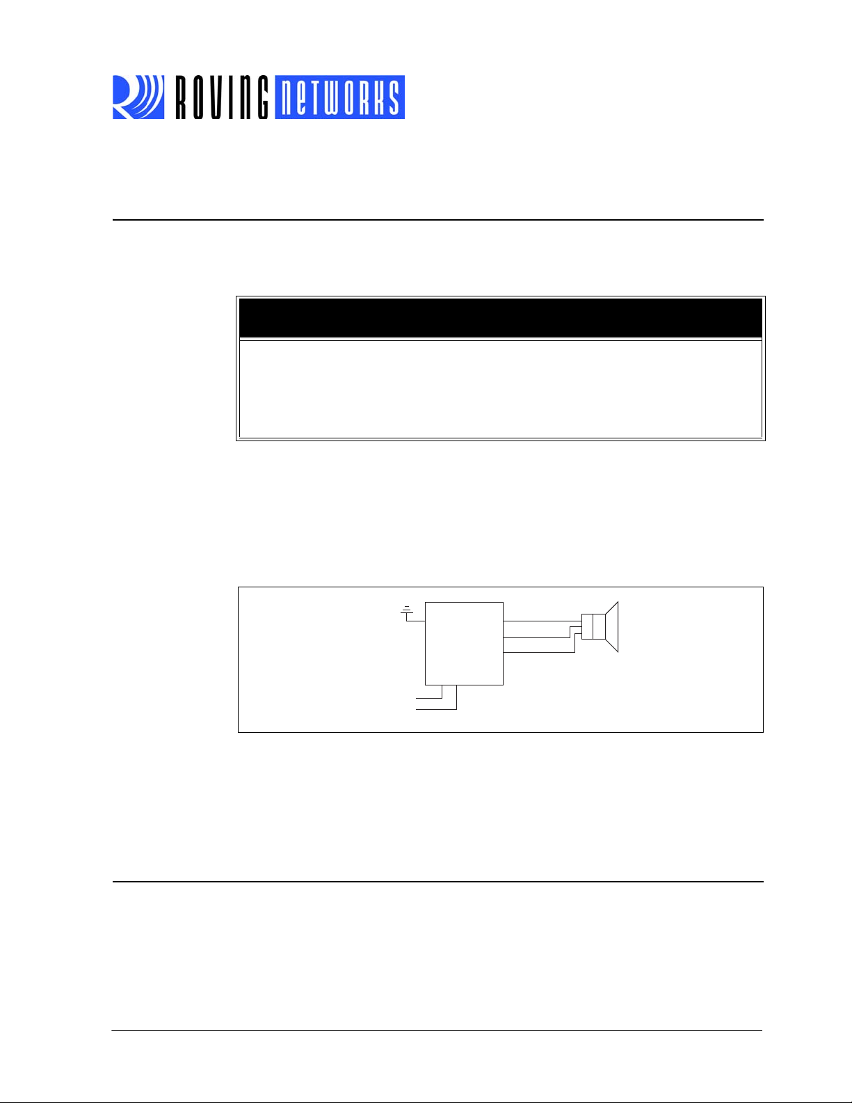
Roving Networks Bluetooth audio modules, such as the RN52, allow you to stream
audio over the Bluetooth link from a source (such as a smartphone) to speakers, a PC,
or other Bluetooth-enabled hardware. In it’s simplest configuration, e.g., controlling
remote speakers, the module only requires five signals to stream audio (left/right
speaker, two grounds, and power). See Figure 1-1.
RN-BT-AUDIO-UG
FIGURE 1-1: BLUETOOTH AUDIO MODULE CONNECTED TO WIRELESS
SPEAKERS
Bluetooth
RN52
Ground
3.3 VDC
This document assumes that you have a working knowledge of Bluetooth operation
and communications. To configure Roving Networks modules you need a Bluetoothenabled smartphone or PC (either built-in or using a USB Bluetooth dongle). You can
only configure one device at a time. Once configured, device settings are saved (independent of power down) until they are explicitly changed or the factory defaults are
restored.
1.2 AUDIO & DATA BLUETOOTH PROFILES
The audio module supports severa l Bluetooth profiles, as described in Table 1-1. Upon
power-up, the module is configured as a slave and is ready to pair and connect. The
A2DP/AVRCP profile is enabled and connected to the SBC CODEC and analog I/O.
Left
Right
Ground
Speake
www.rovingnetworks.com Version 2.0r 3/20/13 page 5
Advanced Information
RN-BT-AUDIO-UG
A
Bluetooth master devices can discover and use the profiles listed in Table 1-1. Y ou con-
figure each profile to be discoverable by using ASCII commands in command mode
over the data interface. The module can enable multiple profile connections simult aneously, and broadcasts the profiles it has available. When you pair the module with a
smartphone, the smartphone decides which profile connection(s) to use.
TABLE 1-1: SUPPORTED BLUETOOTH PROFILES
Profile Type Comments
A2DP Audio The advanced audio distribution profile (A2DP) defines how high quality audio (stereo or mono)
can be streamed from one device to another over a Bluetooth connection.
AVRCP Audio The audio-video remote control profile provides a standard interface to control audio/video equip-
ment such as TVs and hi-fidelity equipment. This profile is dependent on and used with the A2DP
profile.
HFP Audio The hands free profile (HFP) is commonly used in car hands-free kits to communicate with mobile
phones in the vehicle.
HSP Audio The headset profile provides support for using Bluetooth headsets with mobile phones. This pro-
file is dependent on and used with the HFP profile.
SPP Data SPP defines a virtual serial port between two Bluetooth-enabled devices. SPP emulates a bidirec-
tional serial link.
iAP Data The module natively supports iPod Accessory Protocol (iAP) data connections and directly man-
ages authentication with the MFI authentication chip (not inclu ded).
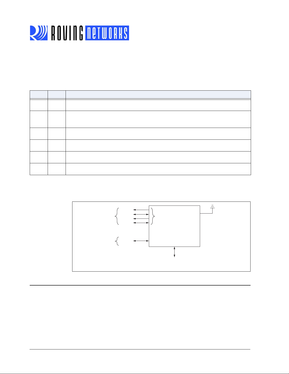
Figure 1-2 shows a block diagram of the RN52 with Bluetooth audio and dat a profiles,
and GPIO pins.
FIGURE 1-2: RN52 PROFILE CONNECTION BLOCK DIAGRAM
1.3 AUDIO SETTINGS
You control the module’s settings through the UART interface using a simple ASCII
command language. For example, you can change the audio r outing and/or profile. Set
commands configure the module and get commands echo the current configuration.
Because the module reads the configuration into RAM once at boot time, configuration
udio
Data
A2DP
AVRCP
HSP
HFP
SPP
iAP
I2S
Analog I/O
S/PDIF
RN52
Bluetooth
Module
UART
GPIO Pins
(Control & Status)
www.rovingnetworks.com Version 2.0r 3/20/13 page 6
Advanced Information

settings modified with the set command do not take effect until the module has been
rebooted (unless otherwise noted), even though the get command may show otherwise. Some example commands are:
SK,08 // Set the connection profile to HFP
GA // Display the authentication mode
GP // Display the pin code
+ // Turn on local echo
V // Display the firmware version
D // Display the current settings
Q // Show the connection status
1.4 MAKING A BLUETOOTH CONNECTION
By default, the Bluetooth module acts as a slave and the PC or smar tphone is the master. You connect to the Bluetooth module using the Bluetooth device manager, which
varies depending on your smartphone or compu ter’s operating system. In all cases, the
process is the same:
• Discovery—In the discovery phase, the Bluetooth module broadcasts its name,
profile support, and MAC address. It is ready for other devices to pair with it. Discovery is only availoable in slave mode.
• Pairing—During pairing, the Bluetooth module and the Bluetooth master validate
the pin code. If the pin code validates successfully, they exch an ge sec ur ity keys
and a channel hopping pseudo-random sequence. Successful pairing results in
the module and master establishing link keys.
• Connecting—Before connecting, the Bluetooth devices must have paired successfully . The m aster initiates a connectio n, the master and slave validate the link
keys, and a Bluetooth link is established.
The following sections describe these processes in detail.
RN-BT-AUDIO-UG
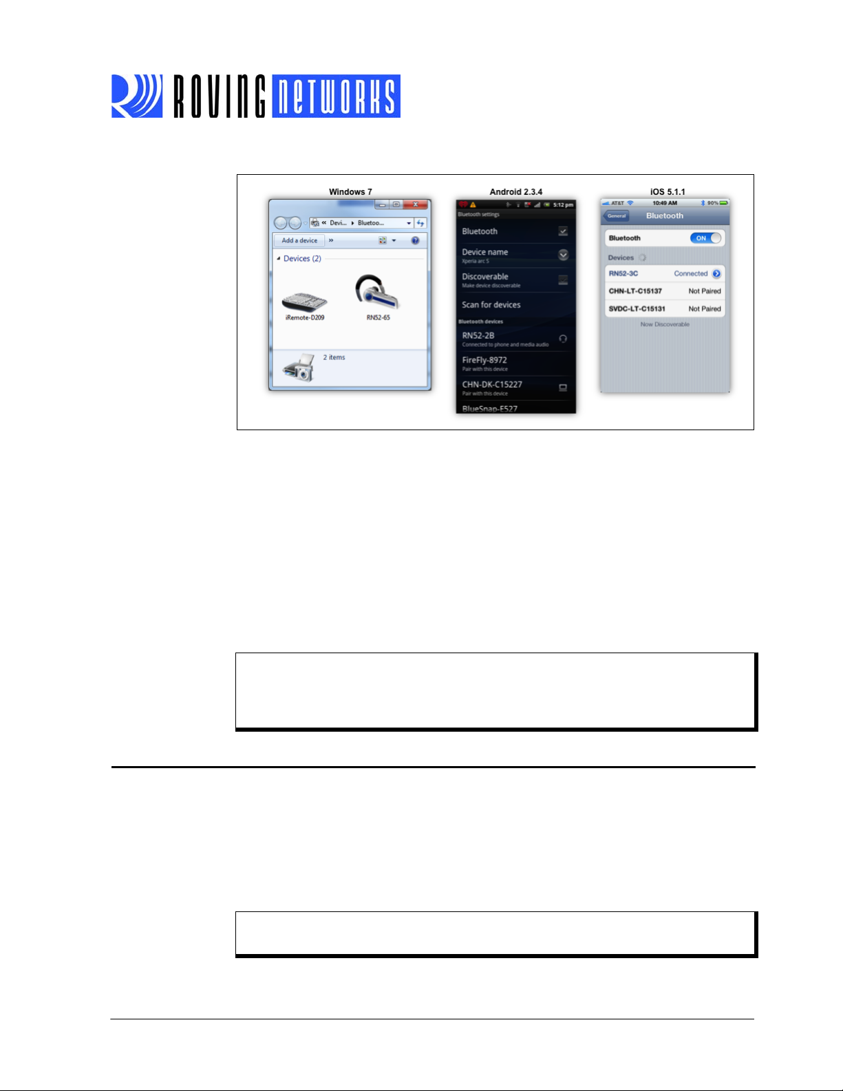
1.4.1 Discovery
Upon power up, the module is discoverable. See Figure 1-3 for Bluetooth device scanning examples. Bluetooth devices, such as smartphones and PCs, can discover the
module.
• Discovery using a smartphone—Touch the Settings icon. For iOS devices, touch
Bluetooth; for Android devices, touch Wireless & networks and then Bluetooth.
The device discovers the module and displays it as RN52-XXXX, where XXXX is
the last 4 digits of the module’s MAC address. The module displays in the available devices list as Not Paired.
• Discovery using a PC—Open your PC’s Bluetooth device manager and choose to
add a new device. The Bluetooth device manager’s icon is located in the bottom
right corner of your screen in the taskbar for Windows and in the upper right corner for Mac OS-X. The Bluetooth device manager displays a list of discoverable
Bluetooth devices. The module displays as RN52-XXXX, where XXXX is the last 4
digits of the module’s MAC address. The module’s label also shows the MAC
address.
www.rovingnetworks.com Version 2.0r 3/20/13 page 7
Advanced Information

RN-BT-AUDIO-UG
1.4.2 Pairing
T o pair with the module, double-click its name in the Blu etooth device list. The module’s
firmware automatically stores up to 8 pairings from remote hosts in a first in, first out
fashion. The default authentication mode is keyboard I/O (no pin code required).
If the remote Bluetooth device does not require authenticatio n, a connection can occur
without the pairing process. However the Bluetooth specification requires that if either
device involved in the pairing process requires authentication, the other device must
participate to ensure a secure link. Roving Networks modules default to SPP open or
keyboard I/O mode and do NOT require authentication.
Most PCs do not support keyboard I/O mode and, therefor e, require authen tication. In
this case, use the module’s default pin code , 1234, as the pass key. After you enter the
pin code, the Bluetooth devices compare them. If they match, a link key is generated
and stored. Usually, but not always, the remote device stores the link key. For subsequent connections, the devices comp are link keys. If they are corr ect, you do not need
to re-enter the pin code.
To remove the stored link key on the remote device, you typically “unpair” or remove
the device from the Bluetooth manager. You can change the pin code to remove the
link key on the Bluetooth adapter, forcing a new pin code exchange to occur upon subsequent connection attempts.
The module may use simple secure pairing (SPP) when it attempts to pair with devices
that support the Bluetooth specification version 2.1 + EDR. SSP does not require the
user to remember the pin code, but it asks to confirm a 6-digit number if the device has
a display capability.
Note: Keyboard I/O mode prompts the host to acknowledge a 6-digit number.
Because there is no way to display this number on an embedded device,
the module always replies with Yes, thereby creating a successful pairing.
This mode is useful for Android devices with operating system 2.3 and
higher.
When you connect to a PC using SPP to exchange data, after the Bluetooth device
manager completes pairing, it issues a message that the Bluetooth device is installed
on COMX where COMX is unique to your computer. This connection is bidirectional. In
some cases, the Bluetooth device manager creates two COM ports. In this situation,
use the incoming port to wait for the module to initiate a connection. Open the outgoing
port to establish a connection to the module.
Figure 1-3 shows some pairing/connecting examples on several platform s.
www.rovingnetworks.com Version 2.0r 3/20/13 page 8
Advanced Information
RN-BT-AUDIO-UG
FIGURE 1-3: PAIRING/CONNECTING WITH THE BLUETOOTH MODULE
1.4.3 Connecting
To establish a Bluetooth connection on a PC, open the module’s COM port from your
application or a terminal emulator. The module remains connected until you close the
COM port or remove power from it.
Once connected, the module is in audio mode, allowing audio ( A2DP) to flow from the
source to the sink.
While sending and receiving audio, the module can transfer and receive data over its
UART. Additionally, you configure the module over the UART by placing the module
into command mode and sending ASCII commands. Command mo de is independent
of the audio function; e.g., the module can play audio as it is going in and out of command mode.
Note: Only one master can connect to a slave device at a time. As a master, the
device can make multiple connections, but only in a point-to-point, serialized manner. Roving Networks modules do not currently support multi-point
master mode.
1.5 COMMAND MODE VS. DATA MODE
The RN52 UART has two modes: data mode (default) and command mode. While in
data mode and connected over Bluetooth (SPP or iAP), the module is essentially a data
pipe. When the module receives data over the wireless Bluetooth connection, it strips
the Bluetooth headers and trailers and passes the user data to the UART. When data
is written to the UART, the module constructs the Bluetooth packet protocol and sends
it out over the Bluetooth connection. Thus, the entire process of sending/receiving dat a
to the host is transparent to the end microprocessor. See Figure 1-4.
Note: The audio stream is unaffected when the module enters/leaves command
mode.
www.rovingnetworks.com Version 2.0r 3/20/13 page 9
Advanced Information
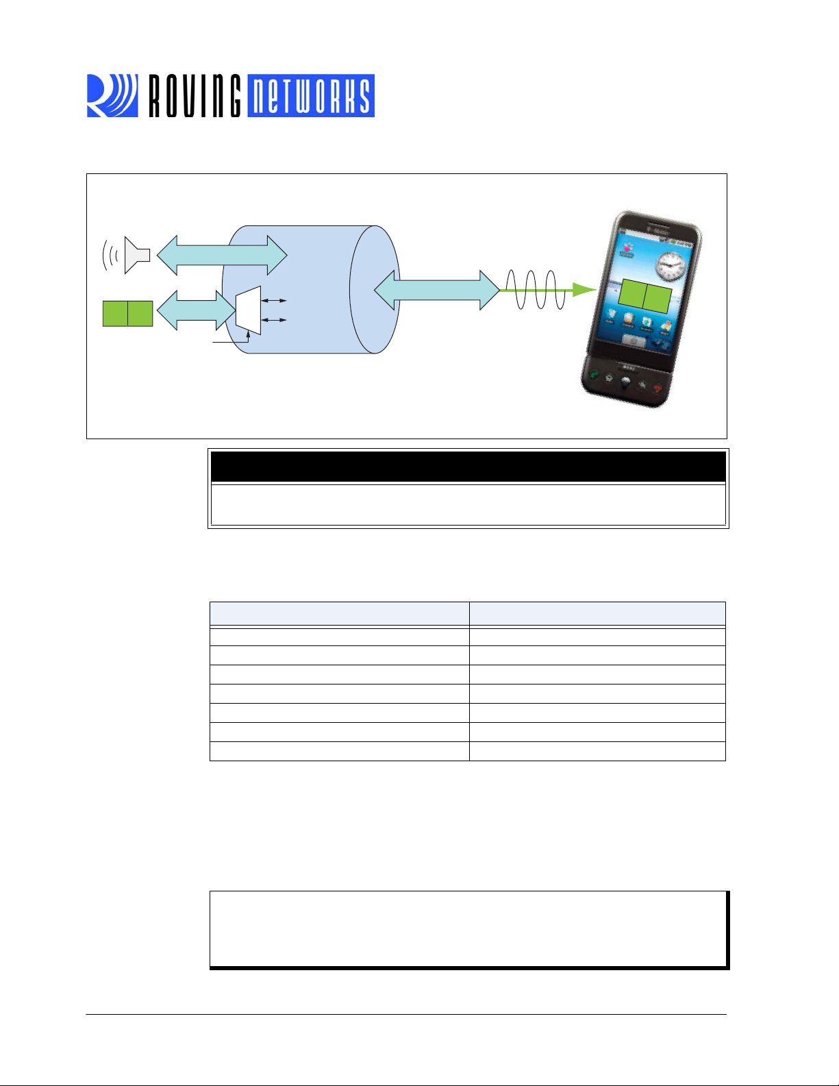
FIGURE 1-4: DATA & COMMAND MODES
Data
RN52
Bluetooth
Module
A
B
Audio
Data
CMD
GPIO9
Bluetooth Protocol
Bluetooth
Host
A
B
RN-BT-AUDIO-UG
NOTICE
You can only configure the Bluetooth audio module locally using your computer’s
serial port. You cannot configure the module remotely over the Bluetooth link.
1.5.1 Default Configuration & Serial Port Settings
Table 1-2 shows the default configuration for the Bluetooth mod ule :
TABLE 1-2: DEFAULT CONFIGURATION & SERIAL PORT SETTINGS
Option Setting
Bluetooth mode Slave
Bluetooth pin code (for legacy pairing modes) 1234
Baud rate 1 15,200 Kbps
Bits 8
Parity None
Stop bits 1
Flow control Disabled
1.5.2 Configuring the Module over the UART
Connect the module to your computer. For example, if you are using the RN-52-EK
evaluation board, connect it to your computer using a USB cable. With the Bluetooth
module connected and powered on, run a terminal em ulator and open the COM port to
which the cable is connected. The terminal emulator’s communication settings should
match the Bluetooth module’s default serial port settings .
Note: You can use local configuration at any time when the device does NOT
have a Bluetooth connection, as well as under certain conditions. If the
device is in configuration mode and a connection occurs, the device exits
configuration mode and data passe s back and forth from the remote device.
www.rovingnetworks.com Version 2.0r 3/20/13 page 10
Advanced Information
RN-BT-AUDIO-UG
UART
DATA
CMD
GPIO9
When you are finished configuring, reset the device, which causes the device to exit
configuration mode and allows data to pass normally.
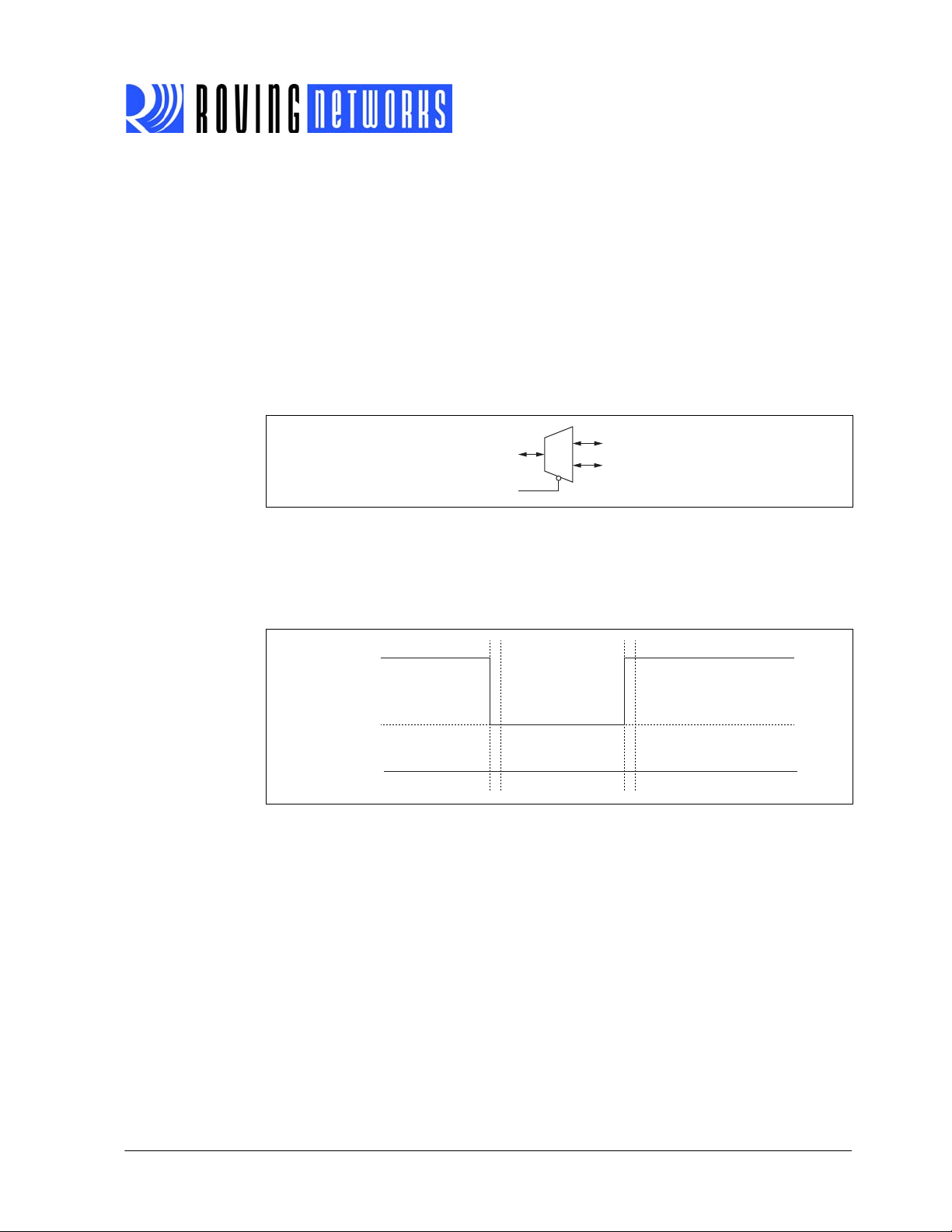
1.5.3 Command Mode & GPIO9
Launch a terminal emulator and specify the module’ s default settings (s ee Table 1-2).
The module monitors GPIO9 as an input to determine whether data traversing the
UART should be routed to the active Bluetooth SPP connection or to the command
console. When you hold GPIO9 low , the UART enters command mode. The module
returns the string
mode. Figure 1-5 shows a logical diagram of the GPIO9 function.
FIGURE 1-5: GPIO9 CONTROLLING COMMAND MODE
In command mode, the module routes all dat a entering the UAR T to the command console. In the command console, you configure the module and query its status using
ASCII commands. See Figure 1-6.
CMD to the UART console to indicate that the module is in command
FIGURE 1-6: PULLING GPIO9 LOW ROUTES UART TRAFFIC TO THE
COMMAND CONSOLE
GPIO9
RN52 UART RX
Data Mode Data ModeCommand Mode
CMD\r\n
END\r\n
High
Low
For applications in which a microcontroller controls GPIO9 and sends command s over
the UART , the microcontroller should monitor the UART RX line for the following strings
immediately after driving GPIO9:
• CMD\r\n
• END\r\n
Use the state diagram shown in Figure 1-7 as a guideline when designing code to monitor GPIO9 and command states.
www.rovingnetworks.com Version 2.0r 3/20/13 page 11
Advanced Information

RN-BT-AUDIO-UG
Timeout
Data Mode
Ready
Wait for
CMD\r\n
Wait for
Command
Wait for
END\r\n
GPIO9
Set Low
CMD\r\n
Received
END\r\n
Received
GPIO9
Set High
ERR
Timeout
Timeout
Action
Send
Command
Receive
Reply
Timeout
FIGURE 1-7: STATE DIAGRAM FOR ENTERING & EXITING COMMAND MODE
While in command mode, the device accepts ASCII bytes as commands. When you
enter a valid command, the module returns
and
? for unrecognized commands. T ype h <cr> to see a list of commands.
A quick check to confirm that you are in command mode is to type the
after entering command mode. This command shows the a summ ary of the module’s
current settings, such as the Bluetooth na m e, de vic e clas s, an d se ria l por t set tin gs.
See Figure 1-8.
To return to data mode, drive GPIO9 high. When leaving command mode the module
sends
END to the UART.
AOK . It returns ERR for an invalid command
D <cr> command
FIGURE 1-8: VIEW CURRENT SETTINGS
www.rovingnetworks.com Version 2.0r 3/20/13 page 12
Advanced Information

RN-BT-AUDIO-UG
1.6 GPIO PINS
The Bluetooth audio module has 11 GPIO pins. Several of these pins are reserved for
specific functions during bootup and runtime. As a demonstration, the RN-52-EK boar d
uses various GPIO pins to control the board’s a udio playback. Table 1-3 describes the
GPIO pins for the standard RN52 module a nd Table 1-4 describes the RN-52-EK GPIO
pin demo function.
TABLE 1-3: RN52 STANDARD GPIO PIN ASSIGNMENTS & FUNCTIONS
GPIO Pin Function Use Direction Default
GPIO2
(Event
Register)
GPIO3
(DFU
Mode)
GPIO4 Factory reset mode. To reset the module to the factory defaults,
GPIO5 Programmable I/O. Runtime,
GPIO6 Programmable I/O. Runtime,
GPIO7 Driving this pin low sets the UART baud rate to 9,600. By default the
GPIO9 When you drive this signal low, the module’s UART goes into com-
GPIO10 Programmable I/O. Runtime,
GPIO11 Programmable I/O. Runtime,
GPIO12 Programmable I/O. Runtime,
GPIO13 Programmable I/O. Runtime,
T oggles from high to low for 100 ms to indicate that the module’s state
has changed. A microcontroller can enter command mode and poll
the state register using the Q action command.
Reserved. Not available for use at runtime.
This pin enters device firmware update (DFU) mode at bootup if a
USB device powers VBUS. GPIO3 requires 47 kΩ to ground and 22
kΩ to the USB VBUS signal if the USB VBUS is supplying power to the
main board.
GPIO4 should be high on power-up and then toggle low, high, low,
high with a 1 second wait between the transitions.
pin is high with a baud rate of 115,200.
mand mode. If this signal floats high, the UART is in data mode.
Reserved. Not available for use at runtime.
Runtime,
Reserved
Bootup,
Configuration
Bootup,
Configuration
Configuration
Configuration
Bootup,
Configuration
Runtime,
Reserved
Configuration
Configuration
Configuration
Configuration
Output High
Input Low
Input Low
I/O High
I/O High
Input High
Input High
I/O High
I/O High
I/O High
I/O High
www.rovingnetworks.com Version 2.0r 3/20/13 page 13
Advanced Information

RN-BT-AUDIO-UG
TABLE 1-4: RN-52-EK (DEMO) GPIO PIN ASSIGNMENTS & FUNCTIONS
GPIO Pin RN-52-EK Demo Function Use Direction Default
GPIO2
(Event
Register)
GPIO3
(DFU
Mode)
GPIO4 Factory reset mode. To reset the module to the factory defaults,
GPIO5 The module uses this signal for the volume up button. Low is active. Runtime,
GPIO6 Input/output at runtime. Runtime,
GPIO7 Driving this pin low sets the UART baud rate to 9,600. By default the
GPIO9 When you drive this signal low, the module’s UART goes into com-
GPIO10 The module uses this signal for the volume down button. Low is
GPIO1 1 The module uses this signal for the previous track button. Low is
GPIO12 The module uses this signal for the next track button. Low is active. Runtime,
GPIO13 The module uses this signal for the play/pause button. Low is active. Runtime,
Toggles from high to low for 100 ms to indicate that the module’s
state has changed. A microcontroller can enter command mode and
poll the state register using the Q action command.
Reserved. Not available for use at runtime.
This pin enters device firmware update (DFU) mode at bootup if a
USB device powers VBUS. GPIO3 requires 47 kΩ to ground and 22
kΩ to the USB VBUS signal if the USB VBUS is supplying power to the
main board.
GPIO4 should be high on power-up and then toggle low, high, low,
high with a 1 second wait between the transitions.
pin is high with a baud rate of 115,200.
mand mode. If this signal floats high, the UART is in data mode.
Reserved. Not available for use at runtime.
active.
active.
Runtime,
Reserved
Bootup,
Configuration
Bootup,
Configuration
Configuration
Configuration
Bootup,
Configuration
Runtime,
Reserved
Runtime,
Configuration
Runtime,
Configuration
Configuration
Configuration
Output High
Input Low
Input Low
Input High
I/O High
Input High
Input High
Input High
Input High
Input High
Input High
1.6.1 Using GPIO2 to Monitor the Event or Status Register
The module contains an event or status register, which you can read to determine status changes. Status changes include changes to profile connections or voice call connections. Y ou access the register with the
the module responds with an encoded 2-byte stream of ASCII hex data terminated by
the
\r\n characters. See “Q” on page 26 for more information on using the Q com-
mand.
The module drives GPIO2 as an output to notify an external micr ocontroller of an event
or status change. The microcontroller should enter command mode and issue the
command and parse the response to retrieve the current status.
The module holds GPIO2 low for 100 ms to indicate a change or event has occured. If
a new event occurs, the register’s data is overwritten with the new event information.
Some bits are cleared when you read the data. See “Q” on page 26 for details.
Figure 1-9 illustrates three event notifications.
www.rovingnetworks.com Version 2.0r 3/20/13 page 14
Advanced Information
Q command. When you issue this command,
Q

FIGURE 1-9: GPIO2 EVENT NOTIFICATION
High
Low
100 ms
100 ms
100 ms
GPIO2
RN52
Speaker
Left
Right
Ground
3.3 VDC
Ground
Streaming Audio Out
Microcontroller
RX
TX
CTS
RTS
GPIO9
GPIO2
Command & Control
1.7 CONNECTING WITH A MICROCONTROLLER
Figure 1-10 shows a simple schematic in which a microcontroller controls the RN52
module. This schematic shows the bare minimum configuratio n requir ed for th e micr ocontroller to perform the following functions:
• Configure and control the module
• Get module’s status information (see “Q” on page 26 for more details)
• Stream audio over the Bluetooth link
For a more complex example of how to control the RN52, refer to the RN-5 2-EK schematic (Figure 1-13 on page 18).
RN-BT-AUDIO-UG
FIGURE 1-10: CONNECTING THE RN52 TO A MICROCONTROLLER
1.8 DEVICE FIRMWARE UPDATES
The module supports the device firmware update (DFU) mode in which you use the
module’s USB interface to update the firmware. Implementing the DFU feature is recommended highly because firmware updates of fer new features and enh ance the module’s functionality. Follow the reference design shown in Figure 1-11 to support this
mode.
Note: A 47 KΩ pull-down resistor (R2 in Figure 1-11) is required on GPIO3 even
if you do not use the USB for DFU.
www.rovingnetworks.com Version 2.0r 3/20/13 page 15
Advanced Information

RN-BT-AUDIO-UG
GND
5
D+
3
D-
2
VBUS
1
MTAB
6
J2
VBUS (3.3V)
USBDUSBD+
47k
R2
22k
R1
GPIO3
MBR120
D1
10nF
C4
USB Mini B Connector
(JAE DX2R005HN2E700)
FIGURE 1-11: USB DFU PORT & GPIO3 SCHEMATIC
When you connect an external USB host into the DFU port and power
enters DFU mode when you reboot or power it. If your board is not powered by
you do not need to include the C4 and D1 to
Figure 1-13 for a more complete design.
1.9 STATUS LEDS
The module can drive status LEDs that gi ve you a visu al confirma tion th at the mod ule
or board is powered up and operating. Table 1-5 describes the status LEDs.
TABLE 1-5: STATUS LED FUNCTIONS
VBUS, the module
VBUS,
VBUS inputs on the voltage regulator. See
Blue LED Red LED Description
Flashing Flashing The RN52 module is discoverable.
Off Flashing The module is connected.
Flashing Off The module is connectable.
www.rovingnetworks.com Version 2.0r 3/20/13 page 16
Advanced Information

1.10 EVALUATION BOARDS & REFERENCE DESIGNS
Roving Networks provides a variety of evaluation kits and reference designs fo r evaluation and prototyping. The RN-52-EK evaluation kit is a prototyping platform for the
RN52 module. The board contains buttons to control a udio playback (volume up/down,
next/previous track, pause/play) and connections for plugging in extern al speakers.
The board has the flexibility to connect directly to PCs via a standard USB interface or
to embedded processors through the TTL UART interface. The status LEDs, switches,
and signal headers enable rapid prototyping and integration into existing systems.
Figure 1-12 and Figure 1-13 show the board and schematic, respectively.
FIGURE 1-12: RN-52-EK EVALUATION KIT
RN-BT-AUDIO-UG
For more information on available evaluation boards and refe rence designs, refer to the
Roving Networks (http://www.rovingnetworks.com) or Microchip (http://www.micro-
chip.com) web sites.
www.rovingnetworks.com Version 2.0r 3/20/13 page 17
Advanced Information

RN-BT-AUDIO-UG
VBUS
VBUS
RESET
18
3V 3OUT
16
USBDP
14
USBDM
15
GND
17
CBUS210CBUS1
21
VCCIO
1
CBUS311CBUS4
9
CBUS0
22
GND
20
RI3DCD7DSR6DTR31CTS8RTS32RXD2TXD
30
VCC
19
OSCI
27
OSCO
28
AGND
2
4
TEST
26
GND
4
THPAD
33
FT232RQ
U1
GND5D+3D-2VBUS
1
MTAB
6
USB Mini B / CSR UART
J1
12345
6
J4
SPI MASTER
SPI _MISO
SPI _MOSI
SPI_SCK
SPI_SS
3.3V
UART_RX
UART_TX
UART_CTS
UART_RTS
Vin
1
GND
2
Vout
3
Tab
4
TC1262- 3.3V U2
1uF
C6
1uF
C7
VBUS 3.3V
100nFC3100nF
C1
100nF
C2
Blue LED
D3
Red LED
D2
S2
Vol Down
S3
Play / Pause
S6
Next
S1
Prev
S4
Vol Up
BTN_VOL UP
BTN_VOL DOWN
BTN_NEXT
BTN_PL AY
BTN_PREVI OUS
47R
R8
470
R9
3.3V
GND5D+3D-2VBUS
1
MTAB
6
USB Mini B / RSVD USB
J2
GPIO45GPIO5
6
GPIO12
7
GPIO13
8
GPIO11
9
GPIO10
10
GPIO9
11
USBD-
12
USBD+
13
UART_RTS
14
UART_CTS
15
UART_TX
16
PCM_CL K
26
SPI _SS28SPI_MISO29SPI_SCK
30
PCM_IN
23
VDD
22
LED033MIC_BIAS34MIC_L+35MIC_R+36MIC_L-37MIC_R-
38
PCM_OUT
24
GPIO7
19
PCM_SY NC
25
SPI_MOSI31LED1
32
PWR EN
21
GPIO6
20
UART_RX
17
AIO0
4
GPIO2
3
AGND39SPKR_R-
40
GND
1
GND
18
GND
27
GND
44
GPIO3
2
SPKR_L-
41
GND
50
GND
49
GND
48
GND
47
GND
46
GND
45
SPKR_R+42SPKR_L +
43
M1
RN52 Module
PIO7
PIO6
LED0
LED1
LED0
LED1
VBUS
USBD-
USBD+
SPI _MISO
SPI _MOSI
SPI_SCK
SPI _SS
3.3V
SPKR_R-
SPKR_L -
SPKR_R+
SPKR_L +
S5
Wake
3.3V
PCM_CLK
PCM_SYNC
PCM_OUT
PCM_IN
SPKR_R-
SPKR_L -
SPKR_R+
SPKR_L +
VBUS
47k
R2
22k
R1
PIO3
1uF
C21
1uF
C22
1uF
C13
1uF
C14
1uF
C12
2k2
R7
2k2
R6
47nFC847nF
C10
47nF
C11
47nF
C9
MIC_L
MIC_R
1uF
C18
22k
R17
22k
R15
47k
R11
22k
R13
47k
R14
47k
R10
47k
R16
22k
R12
1 2
3 4
5 6
7 8
9 10
11 12
13 14
15 16
J3
EXT Connector
PCM_CL K
PCM_SYNC
PCM_OUT
PCM_I N
3.3V
IN1+3IN1-
2
Vo2
9
BYPASS4IN2-8IN2+
7
SHUTDOWN
6
GND
5
VDD
10
Vo1
1
PAD
11
U4
TPA6112
100uF
C23
100uF
C20
100uF
C17
100uF
C19
10uF
C15
100nF
C16
MBR120
D1
10nF
C4
VBUS
PIO9
3.3V
BTN_VOLDOWN
BTN_PREVI OUS
BTN_PLAY
BTN_NEXT
BTN_VOLUP
PIO2
PIO6
PIO7
1
2
J8
MI CL
1
2
J6
MI CR
MIC_L
MIC_R
1
2
J11
Battery
VBUS
1234567891011
12
J10
1 2
3 4
5 6
7 8
9 10
J7
PIO4
PWREN
PWREN
SPKR_R-
SPKR_L -
SPKR_R+
SPKR_L +
MIC_BI AS
MIC_L +
MIC_R+
MIC_L -
MIC_R-
MI C_L +
MIC_R+
MI C_L -
MIC_R-
MIC_BI AS
AI O0
UART_RX
UART_TX
UART_CTS
UART_RTS
USBD-
USBD+
BTN_VOL UP
BTN_VOL DOWN
BTN_NEXT
BTN_PLAY
BTN_PREVI OUS
PIO3
PIO9
PIO2
PIO4
AI O0
MIC_L +
MIC_R+
MIC_L -
MIC_R-
MIC_BI AS
35421
J5
Mic
354
2
1
J9
Headphones
2k2R70
UART_RX
UART_TX
FIGURE 1-13: RN-52-EK SCHEMATIC
Advanced Information
www.rovingnetworks.com Version 2.0r 3/20/13 page 18

Chapter 2. Command Reference
Roving Networks Bluetooth modules support a variety of comman ds for configuration .
This section describes these commands in detail and provides examples.
NOTICE TO CUSTOMERS
The commands and applications described in this document apply to
Roving Networks Bluetooth audio modules, e.g., the RN52 . They do not
apply to Roving Networks Bluetooth data modules such as the RN41 or
RN42. For data module configuration information, refer to the Bluetooth
Data Module Command Reference & Advanced Information User’s Guide.
2.1 COMMAND SYNTAX
To issue commands to the module, you send a keyword followed by optional parameters via the UART.
• All commands are one or two characters and can be upper or lower case.
• Delimit command arguments with a comma.
• Commands use decimal input, except wher e no te d.
• Text data, such as the Bluetooth name and pin code, is case sensitive.
There are three general command categories, as shown in Table 2-1.
TABLE 2-1: COMMAND TYPES
Command Type Description
Set commands Store information to flash memory. Changes take effect after a power
cycle or reboot.
Get commands Retrieve and display the stored information.
Action commands Perform actions such as controlling the audio playback, performing inqui-
ries, connecting, etc.
RN-BT-AUDIO-UG
Set commands only take effect AFTER reboot, except where noted. Get and action
commands take effect immediately.
Each command terminates with the carriage return (\r).
www.rovingnetworks.com Version 2.0r 3/20/13 page 19
Advanced Information

2.2 SET COMMANDS
Set commands specify configuration settings and take effect after power cycling or
rebooting. Commands are not case sensitive. All commands respond with
AOK,<optional message>\r\n for success or ERR,<optional message>\r\n if the com-
mand fails.
2.2.1 S|,<value>
This command sets the routing for the audio output, where <value> is a value shown
in Table 2-2.
TABLE 2-2: AUDIO ROUTING VALUES
Value Description
00 Analog output (default).
01 Set the output for I
02 Set the output for S/PDIF.
TABLE 2-3: RN52 I2S SETTINGS
Parameter Value
Configuration Master mode.
Supported sample rates Variable.
Sample width 24 bits.
Synchronous data Data is right channel with word select (WS) high. The SD data MSB
Justification Left justified.
ports.
RN-BT-AUDIO-UG
2
S. See Table 2-3 for the I2S settings the RN52 interface sup-
occurs in the second SCLK period.
Default: 00
Example:
S|,02 // Set the audio output to S/PDIF
2.2.2 S-,<string>
This command sets the module’s normalized name where <string> is a prefix of up to
15 alphanumeric characters. The module’s name is set to <string>-XXXX, where XXXX
is the last four digits of the module’s MAC address.
This setting is useful for situations in which you want to set up multiple modules with
simular but unique identifiers.
Default: RN52
Example:
www.rovingnetworks.com Version 2.0r 3/20/13 page 20
S-,MCHIP // Set module’s name to MCHIP-XXXX
Advanced Information

RN-BT-AUDIO-UG
2.2.3 SA,<value>
The set authentication command forces authentication when a remote device attempts
to connect, where <value> is a decimal value shown in Table 2-4. Regardless of this
setting, if a remote device forces authentication, this device responds with the stored
pin code. Once a remote device has exchanged pin codes with this device, a link key
is stored for future use. The de vice stores up to 8 keys automatically an d permanently
in flash memory, in a first in, first out fashion.
TABLE 2-4: SET AUTHENTICATION VALUES
Value Description
0 Open. Authentication is not required. The device accepts pin code mode.
1 SSP keyboard I/O mode (default). If this option is set, the remote host receives a prompt; reply yes to pair.
Optional does not force this mode but accepts it if the host requires (e.g., Droid 3.3+). The host posts a message asking for confirmation; the module always responds yes.
2 SSP “just works” mode. You can use this mode with Droid devices if the application connects using unsecure
mode (which was the default on Droid version 3.3). This mode also works with new PC stacks.
4 Pin code. Forces pin code mode, which requires the host device to enter a pin code that matches the stored
pin code.
Note: Modes 0 and 4 are legacy modes that do not support SSP (Bluetooth ver-
sion 2.0).
Default: 1 // Keyboard mode
Example:
SA,4 // Set to pin code mode
2.2.4 SC,<24-bit hex value>
This command sets the service class field in the class of device (COD), where <24-bit
hex value> represents the COD. Bluetooth master devices use the COD when scan-
ning for available devices to determine whether a device in a given class of fers the type
of service that they want.
The service class consists of the most significant 11 bits in the COD. This command
sets the MSW to create the 24-bit device class number. The inquiring device interprets
the service class to determine the service. A complete listing of available Bluetooth service classes is available on the Bluetooth SIG web site (https://www.blue-
tooth.org/apps/content).
The default COD, 240704, represents the following device:
• Service class: rendering, audio
• Major device class: wearable
• Minor device class: wrist watch
Default: 240704
Example:
SC,240710 // Service class: rendering, audio
// Major device class: wearable
// Minor device class: helmet
www.rovingnetworks.com Version 2.0r 3/20/13 page 21
Advanced Information

RN-BT-AUDIO-UG
2.2.5 SD,<8-bit hex value>
This command sets the discovery mask, where <8-bit hex value> represents the profiles enabled for discovery. The Bluetooth profiles are represented by an 8-bit hex value
as shown in Table 2-5.
TABLE 2-5: BLUETOOTH PROFILE BITMASK VALUES
Bit Position Value Profile
0 01 iAP
1 02 SPP
2 04 A2DP
3 08 HFP
Default: FF
Example:
2.2.6 SF,1
This command sets all module parameters to the factor y defaults. The changes do not
take effect until you reboot the module.
SD,01 // Set the discovery profile to iAP
Note: When performing a factory reset using a microcontroller, send the SF,1
Example:
command, wait for 20 ms, send the
to return
SF,1 // Invoke factory defaults
R,1 // Reboot
reboot. Then, drive GPIO9 high to exit command mode.
R,1 command, and wait for the module
2.2.7 SK,<8-bit hex value>
This command sets the connection mask where <8-bit hex value> represen ts the profiles enabled for connection. The Bluetooth profiles are represented by an 8-bit hex
value as shown in Table 2-6.
TABLE 2-6: BLUETOOTH PROFILE BITMASK VALUES
Bit Position Value Profile
0 01 iAP
1 02 SPP
2 04 A2DP
3 08 HFP
Default: FF
Example:
SK,08 // Set the connection profile to HFP
2.2.8 SN,<string>
This command sets the device name, where <string> is up to 20 alphanumer ic characters.
Default: RN52-XXXX, where XXXX is the last 4 digits of the module’s MAC address.
When you set the name, the -XXXX is not appended to <string>.
Example:
www.rovingnetworks.com Version 2.0r 3/20/13 page 22
SN,MyDevice // Set the device name to “MyDevice”
Advanced Information

2.2.9 SP,<string>
This command sets the security pin code, where <string> is up to 20 alphanumeric
characters. Each time the device pairs successfully, it saves the Bluetooth address.
The device can store up to eight addresses on a first in first out basis. Using this command also erases all stored pairings. You can use the same value that is already set.
You cannot erase the pin code, however, you can overwrite the default pin code.
Default: 1234
Example:
2.3 GET COMMANDS
Get commands retrieve and display the device’s stored information. These commands
do not have a keyword or character and do not take any parameters, except as noted.
Commands are not case sensitive. All commands respond with
sage>\r\n for success or
2.3.1 D
RN-BT-AUDIO-UG
SP,0123 // Set pin code to 0123
AOK,<optional mes-
ERR,<optional message>\r\n if the command fails.
This command displays basic settings such as the address, name, UART settings,
security, pin code, bonding, and remote address. Figure 2-1 shows an example of the
output.
Example:
FIGURE 2-1: DISPLAY COMMAND EXAMPLE OUTPUT
D // Display basic settings
www.rovingnetworks.com Version 2.0r 3/20/13 page 23
Advanced Information

2.3.2 G<command>
This command displays the stored settings for a set command, where <command> is
the second character of a set command.
Example:
GA // Display the authentication mode
GP // Display the pin code
2.3.3 H
The help command displays a list of commands and their basic syntax.
Example:
H // Display help
2.3.4 V
This command displays the firmware version.
Example:
V // Show the firmware version
2.4 ACTION COMMANDS
RN-BT-AUDIO-UG
Action commands perform actions such as audio playback, inquiries, connecting, and
entering/exiting command mode. Commands are not case sensitive.
2.4.1 +
This command toggles the local echo on and off. If you send the + command in command mode, all typed characters are ec ho ed to the ou tp ut . Typing
turns local echo off.
Default: Off
Example:
+ // Turn local echo on
+ a second time
2.4.2 @,<flag>
This command toggles whether the module is discoverable, where <flag> is 1 (discoverable) or 0 (not discoverable).
Example:
@,1 // Make the module discoverable
2.4.3 A,<telephone number>
This command initiates a voice call to a telephone, where <telephone number> is a
decimal telephone number up to 25 digits. The module returns an error (
status is not idle.
Example:
A,14083955300 // Call 1 (408) 395-5300
ERR) if the call
2.4.4 AV+
This command increases the volume.
2.4.5 AV-
This command reduces the volume.
www.rovingnetworks.com Version 2.0r 3/20/13 page 24
Advanced Information

RN-BT-AUDIO-UG
2.4.6 AT+
This command plays the next track by sending an AVRCP volume previous track command to the host.
2.4.7 AT-
This command plays the previous track by sending an AVRCP volume previous track
command to the host.
2.4.8 AP
This command pauses or starts playback by sending an AVRCP volume pause/play
command to the host.
2.4.9 B
The module attempts to reconnect the Bluetooth profiles specified in the connection
mask to the most recently paired device. See “SK,<8-bit hex value>” on page 22.
Use the
(bits 0 - 3). The module returns an error if it has not been previously connected or if the
connection mask is set to 00 (meaning the module is not connectable).
Q command to retrieve the Bluetooth profile connection status in byte 0
2.4.10 C
This command instructs the module to accept an incoming voice call. You use the Q
command to retrieve the call status (bits 8 - 10) value. The module returns an error
(
ERR) if the call status is not set to incoming calls.
Example:
C // Accept incoming call
2.4.11 E
This command terminates an active call or reject s an incoming call. The module returns
an error (
Example:
ERR) if the call status is not an incoming call or active call.
E // Terminate call
2.4.12 HV,<value>
This command sends a volume adjustment command to the telephone to adjust the
voice call volume and synchronize the volume levels. <value> is the level in decimal
integers from 0 - 15, and conforms to the HFP specification version 1.8 4.28.2.
Example:
HV,8 // Set volume to level 8
www.rovingnetworks.com Version 2.0r 3/20/13 page 25
Advanced Information

RN-BT-AUDIO-UG
2.4.13 K,<8-bit hex value>
This command disconnects the currently active connection, where <8-bit hex value>
represents the profile to disconnect. The characters
local UART once the connection is broken. The Bluetooth profiles are represented by
an 8-bit hex value as shown in Table 2-7.
TABLE 2-7: BLUETOOTH PROFILE BITMASK VALUES
Bit Position Value Profile
0 01 iAP
1 02 SPP
2 04 A2DP
3 08 HFP
KILL<cr><lf> are echoed to the
Example:
K,01 // Disconnect the iAP profile
2.4.14 M,<flag>
This command controls the hold/mute function for the current telephone call, where
<flag> is 0 or 1. If <flag> is 1, the module mutes the call; if <flag> is 0, the call is
unmuted.
Example:
M,1 // Mute the call
2.4.15 Q
This command queries the current connection status in the event/status register. It
returns an encoded byte stream of ASCII hex values terminated by \r\n to describe the
status of the currently connected profile(s). The module drives GPIO2 low for 100 ms
to notify attached equipment that the event/status register has been changed. See
“Using GPIO2 to Monitor the Event or Status Register” on page 14 for more informa-
tion.
Byte 0 of the byte stream indicates which profiles are connected as shown Table 2-8.
TABLE 2-8: BYTE 0 BIT FORMAT
Bit Description
0 iAP wireless active connection to remote device.
1 SPP active connection to remote device.
2 A2DP active connection to remote device.
3 HFP/HSP active connection to remote device.
4 - 7 Reserved.
www.rovingnetworks.com Version 2.0r 3/20/13 page 26
Advanced Information

RN-BT-AUDIO-UG
Table 2-9 describes the bits in byte 1. Note that:
• The connection state values (bits 0 - 3) only change when the module’s status
changes.
• The event bits (4 - 6) in byte 0 are cleared when you issue the
TABLE 2-9: BYTE 1 BIT FORMAT
Bit Description
0 - 3 These bits indicate the connection state. See Table2-3 for a listing of the possible states.
4 HFP audio volume level change from audio gateway (phone). Use the Y,0 command to retreive the volume
level. The module clears this bit when you read the event/status register qith the Q command.
5 HFP audio microphone level change from audio gateway (phone). Use the Y,1 command to retreive the vol-
ume level. The module clears this bit when you read the event/status register qith the Q command.
6 - 7 Reserved.
Table 2-3 describes the connection states in bits 0 - 3 of byte 1.
TABLE 2-10: BYTE 1 CONNECTION STATES
Value State Description
0 Limbo Logically off, but physically on.
1 Connectable The module is connectable, page scanning.
2 Connectable and discoverable The module is connectable and discoverable, page and inquiry scanning.
3 Connected The module is connected to an audio gateway.
4 Outgoing call established The connected audio gateway has an outgoing call in progress.
5 Incoming call established The connected audio gateway has an active call in progress and the audio
is in the headset.
6 Active call The connected audio gateway has an active call in progress and the audio
is in the headset.
7 Test mode The headset is in test mode.
8 Three-way call waiting The connected audio gateway has an active call and a second call on hold.
9 Three-way call on hold The conneted audio gateway has an active call and a second call on hold.
10 Three-way call multi-call The connected audio gateway has an active call and a second call on hold.
11 Incoming call on hold The connected audio gateway has an incoming call on hold.
12 Active call The connected audio gateway has an active call and the audio is in the
handset.
13 Audio streaming The headset is streaming A2DP audio.
14 Low battery The system has a low battery.
Q command.
Example:
0C16\r\n \\ Indicates that the A2DP and HFP
\\ profiles are connected, the call status is
\\ active, and that an audio mute/hold
\\ event was received from the phone.
www.rovingnetworks.com Version 2.0r 3/20/13 page 27
Advanced Information

RN-BT-AUDIO-UG
2.4.16 R,1
This command forces a complete device reboot (similar to a power cycle). After you
send this command, the module responds
reboot.
Note: When performing a factory reset using a microc ontroller , send the
mand and then wait for the module to return
reboot. Then, drive GPIO9
R,1 com-
high to exit command mode.
Example:
R,1 // Reboot the device
2.4.17 Y,<flag>
This command returns either the last speaker (<flag> = 0) or microphone level
(<flag> = 1) as a 0 - 15 decimal value sent from the audio gateway in response to bits
14 and 15 in the event status register.
Example:
Y,0 // Returns the speaker volume
www.rovingnetworks.com Version 2.0r 3/20/13 page 28
Advanced Information

RN-BT-AUDIO-UG
Appendix A. Command Quick Reference Guide
This section provides a quick reference of the firmware commands as well as the factory defaults. Table A-1 provides an overview of the set commands.
TABLE A-1: SET COMMANDS
Command Description Factory Settings
S|,<hex value> Audio output routing. 00 (analog output)
S-,<string> Sets the normalized name. RN52
SA,<0,1,2,4> Authentication enable/disable. 1 (SPP keyboard I/O)
SC,<hex value> Service class. 240704
SD,<hex value> Discovery profile mask. FF
SF,1 Factory defaults. N/A
SK,<hex value> Connection profile mask. FF
SN,<string> Device name. RN52-XXXX
SP,<string> Pin code. 1234
Table A-2 describes the get (or display) commands.
TABLE A-2: GET (DISPLAY) COMMANDS
Command Description
D Basic settings.
G<command> Displays setting for the set command indicated by <command>.
H Display help.
V Display the firmware version.
Table A-3 describes the action commands.
TABLE A-3: ACTION COMMANDS
Command Description
+ Toggle the local echo of RX characters in command mode.
@,<flag> Toggle whether the module is discoverable.
A,<telephone number> Initial a voice call to <telephone number>.
AV+ Increase the volume (AVRCP command).
AV- Decrease the volume (AVRCP command).
AT+ Play the next track (AVRCP command).
AT- Play the previous track (AVRCP command).
AP Pause or start playback (AVRCP command).
B Reconnect Bluetooth profiles to the mnost recently paired and connected device.
C Accept an incoming voice call.
E Terminate an active call or reject an incoming call.
HV,<value> The module sends a volume adjustment command to the telephone.
K,<hex value> Kill the currently active connection.
M,<flag> Toggle the on hold/mute function.
Q Query the current connection status.
R,1 Reboot.
Y,<flag> Return either the last speaker or microphone level.
www.rovingnetworks.com Version 2.0r 3/20/13 page 29
Advanced Information

NOTES:
RN-BT-AUDIO-UG
www.rovingnetworks.com Version 2.0r 3/20/13 page 30
Advanced Information

Appendix B. Firmware Revision History
The following sections provide the firmware revision history.
B.1 VERSION 1.05
• First release.
RN-BT-AUDIO-UG
www.rovingnetworks.com Version 2.0r 3/20/13 page 31
Advanced Information

NOTES:
RN-BT-AUDIO-UG
www.rovingnetworks.com Version 2.0r 3/20/13 page 32
Advanced Information

Appendix C. Document Information
CONVENTIONS USED IN THIS GUIDE
This manual uses the following documentation conventions:
DOCUMENTATION CONVENTIONS
Description Represents Examples
Arial font:
Italic characters Referenced books MPLAB
Emphasized text ...is the only compiler...
Initial caps A window the Output window
A dialog the Settings dialog
A menu selection select Enable Programmer
Quotes A field name in a window or
dialog
Underlined, italic text with
right angle bracket
Bold characters A dialog button Click OK
N‘Rnnnn A number in verilog format,
Text in angle brackets < > A key on the keyboard Press <Enter>, <F1>
Courier New font:
Plain Courier New Sample source code #define START
Italic Courier New A variable argument file.o, where file can be
Square brackets [ ] Optional arguments mcc18 [options] file
Curly braces and pipe
character: { | }
Ellipses... Replaces repeated text var_name [,
A menu path File>Save
A tab Click the Power tab
where N is the total number of
digits, R is the radix and n is a
digit.
Filenames autoexec.bat
File paths c:\mcc18\h
Keywords _asm, _endasm, static
Command-line options -Opa+, -Opa-
Bit values 0, 1
Constants 0xFF, ‘A’
Choice of mutually exclusive
arguments; an OR selection
Represents code supplied by
user
RN-BT-AUDIO-UG
®
IDE User’s Guide
“Save project before build”
4‘b0010, 2‘hF1
any valid filename
[options]
errorlevel {0|1}
var_name...]
void main (void)
{ ...
}
www.rovingnetworks.com Version 2.0r 3/20/13 page 33
Advanced Information

RECOMMENDED READING
This user’s guide describes how to configure Roving Networks Bluetooth modules. The
module-specific data sheets contain current information on the module specifications.
Other useful documents are listed below. The following Microchip documents are available and recommended as supplemental reference resources:
RN52 Bluetooth Audio Module Data Sheet
This document provides the technical specifications for the RN52 module.
RN-52-EK Evaluation Kit User’s Guide
This document describes how to use the RN-52-EK ev alu at ion ki t and pro vid e s an
audio demonstration.
To obtain any of these documents, visit the Microchip web site a t www.microchip.com.
DOCUMENT REVISION HISTORY
RN-BT-AUDIO-UG
Version 2.0 (March 2013)
Added more details on the module’s audio operation.
Version 1.0 (January 2013)
This is the initial released version of the document.
www.rovingnetworks.com Version 2.0r 3/20/13 page 34
Advanced Information
 Loading...