


RN-52-EK-UG
RN-52-EK Evaluation Kit User’s Guide
© 2013 Roving Networks. All rights reserved.
RN-52-EK-UG Version 1.0 1/27/13

Copyright © 2013 Roving Networks. All rights reserved. Roving Networks
is a registered trademark of Roving Networks. Apple Inc., iPhone, iPad,
iTunes, Made for iPhone are registered trademarks of Apple Computer.
Roving Networks reserves the right to make corrections, modifications,
and other changes to its products, documentation and services at any
time. Customers should obtain the latest relevant information before placing orders and should verify that such information is current and complete.
Roving Networks assumes no liability for applications assistance or customer’s product design. Customers are responsible for their products and
applications that use Roving Networks components. To minimize customer product risks, customers should provide adequate design and operating safeguards.
Roving Networks, Inc.
102 Cooper Court
Los Gatos, CA 95032
+1 (408) 395-5300
www.rovingnetworks.com
www.rovingnetworks.com Version 1.0 1/27/13 page 2
Roving Networks products are not authorized for use in safety-critical
applications (such as life support) where a failure of the Roving Networks
product would reasonably be expected to cause severe personal injury or
death, unless officers of the parties have executed an agreement specifically governing such use.
Advanced Information
RN-52-EK-UG
1.0 OVERVIEW
This document describes the hardware and software setup for the Roving Networks RN-52-EK
evaluation kit. This kit contains the hardware you need to evaluate the RN52 Bluetooth aud io
module. The RN52 module is mounted to an evaluation board th at demonstrates the module’s
key features. The board contains:
• Dual-channel audio output and input
• Easy access to GPIO pins
• Built-in amplifier for stereo audio output
• 6 pushbuttons to control audio playback
•Status LEDs
• Connections for the programmer and UART interfaces
The RN52 supports the following Bluetooth profiles:
• A2DP stereo audio (sink mode with an SBC CODEC)
• AVRCP media player remote control
• HFP/HSP for accepting a phone call from a mobile phone
• SPP (allows the module to receive serial data over the UART)
• iAP profile discovery for iOS devices
You use the evaluation kit to configure and program the Bluetooth mo dule using the comma nd
interface, create connections, and transfer data. The command interface is made u p of simple
ASCII commands. See “Resources & Related Documents” on page 12 for information on available documentation.
2.0 EVALUATION KIT DESCRIPTION
The evaluation kit includes the hardware required to conn ect the eva luatio n board to your computer. See Table 2-1. To evaluate the module on the evaluation board, you need a computer with
a USB port running the Microsoft Windows or Mac OS-X operating system.
Note: Before beginning your evaluation, you may need to install the driver for the USB
cable. Y ou can download the driver (as well as other tools and utilities) from the Roving Networks website at http://www.rovingnetworks.com/support.php.
TABLE 2-1: EVALUATION KIT CONTENTS
Hardware Description
Evaluation board Contains the Bluetooth module and connectors.
Mini-USB cable Links your computer to the evaluation board.
Stereo mini-speakers USB powered speakers.
RN52 samples Kit includes two sample RN52 modules.
Figure 1-1 provides the RN-52-EK evaluation board and pin information.
www.rovingnetworks.com Version 1.0 1/27/13 page 3
Advanced Information
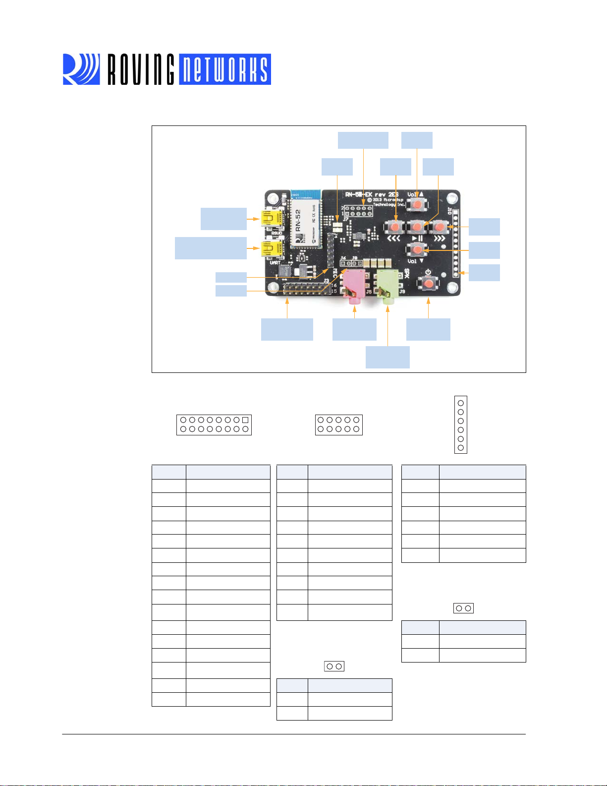
FIGURE 1-1: RN-52-EK EVALUATION BOARD
161412
151311
210864
19753
210864
19753
1
2
3
4
5
6
12
12
Differential
Audio In/Out (J7)
Volume
Up
RN-52-EK-UG
USB to Module
(HCI Mode)
USB to UART
(SPP & Command Mode)
SPI (J4)
Audio In
PCM In/Out, AIO0, GPIO9
(J3)
Status
LEDs
PCM In/Out
AIO0, GPIO9 (J3)
Differential Audio In/Out
(J7)
Audio In
3.5 mm TRR
Previous
Track
Audio Out
3.5 mm TRR
Pause/
Play
Power On
Pairing Mode
SPI (J4)
Next
Track
Volume
Down
GPIO
Pins
Pin Description Pin Description Pin Description
1 UART_TX 1 SPKR_R- 1 SPI_MISO
2 VBUS 2 MIC_L+ 2 SPI_MOSI
3 UART_RX 3 SPKR_L- 3 SPI_SCK
4 AIO0 4 MIC_R+ 4 SPI_SS
5 GPIO9 5 SPKR_R+ 5 3.3 V
6GND 6MIC_L- 6 GND
7 GND 7 SPKR_L+
8 PCM_IN 8 MIC_R- MIC Left (J8)
9GND 9GND
10 PCM_OUT 10 MIC_BIAS
11 GND
Pin Description
12 PCM_SYNC MIC Right (J6) 1MIC_L
13 GND 2 GND
14 PCM_CLK
15 GND
Pin Description
16 3.3 V 1 MIC_R
2GND
www.rovingnetworks.com Version 1.0 1/27/13 page 4
Advanced Information
RN-52-EK-UG
3.0 HARDWARE SETUP
To set up the evaluation hardware, perform the following steps:
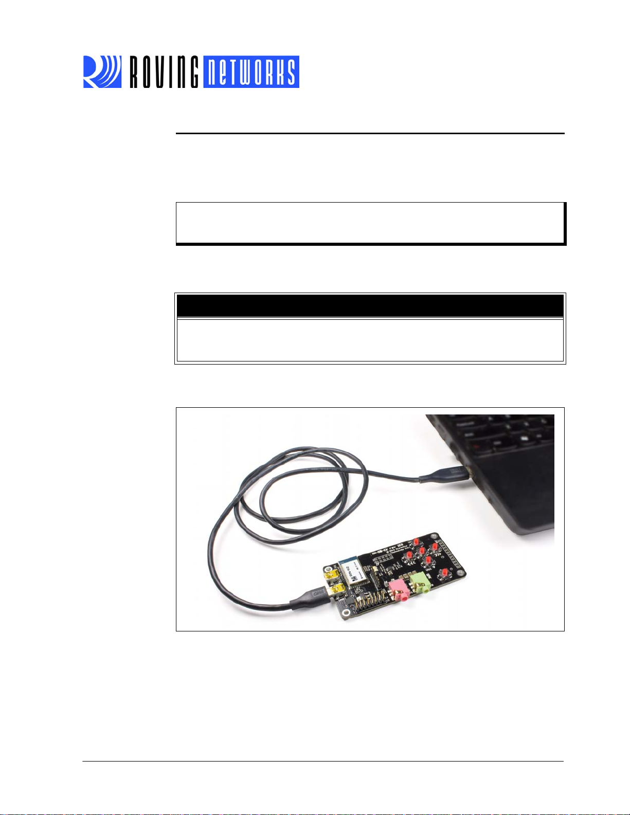
1. Connect the min-USB cable to your computer ’s USB port and to the evaluation board’s
UART connector. This connection provides power to the board and provides a data connection to the command console.
Note: Windows should automatically install the drivers for the cable. If it does not, down-
load and install the FTDI drivers from the Support page on the Roving Networks
website at http://www .rovingnetworks.com/support.php.
2. Note the COM port to which you have attached the cable.
3. Connect the portable mini-speaker 3.5 mm TRR plug to the stereo audio out connector
(J9). The mini speakers are powered via USB.
CAUTION
Roving Networks recommends that you connect the RN-52-EK evaluation board and
min-speakers to different USB sources to avoid a ground loop that causes noise in the
audio output.
Figure 1-2 shows the completed hardware setup for the evaluation board.
FIGURE 1-2: COMPLETED HARDWARE SETUP
www.rovingnetworks.com Version 1.0 1/27/13 page 5
Advanced Information

RN-52-EK-UG
UART
Bluetooth Interface
Bluetooth
Module
Command
Mode
GPIO9 Driven Low
with a Jumper
A
B
User Data
Bluetooth
Host
A
B
4.0 POWER UP THE BOARD
To power up the boa rd, conne ct the board and mi ni-spea kers to a power source vi a USB. Then
press and hold the board’s power on button until the speakers issue a two tone alert.
The board’s status LEDs give you a visual confirmation that the board is powered up and operating. See Table 4-1.
TABLE 4-1: STATUS LEDS
LED Status Description
Blue and red Flashing The RN52 module is discoverable.
Blue only Flashing The module is connectable.
Red only Flashing The module is connected.
5.0 USING THE EVALUATION KIT
This section assumes that you have a working knowledge of Bluetooth operation and communications. T o program the Roving Networks devices you need a Bluetooth-enabled PC (either builtin or using a USB Bluetooth dongle). You can only program one device at a time. Once programmed and configured, device settings are saved (independent of power down) until they are
explicitly changed or the factory defaults are restored.
5.1 Command Mode vs. Data Mode
The Bluetooth device operates in two modes: data mode (default) and command mode. While in
data mode, the module is essentially a data pipe. When th e module receives data, it strips the
Bluetooth headers and trailers and passes the user data to the UART. When data is written to the
UART, the module constructs the Bluetooth packet and sends it out over the Bluetoo th connection. Thus, the entire process of sending/receiving data to the host is transparent to the end
microprocessor. See Figure 1-3.
FIGURE 1-3: DATA & COMMAND MODES
www.rovingnetworks.com Version 1.0 1/27/13 page 6
Advanced Information

RN-52-EK-UG
The default configuration for the Bluetooth device is:
• Bluetooth slave mode
• Keyboard default authentication mode (no pin code required)
• Serial port 115,200 Kbps baud rate, 8 bits, no parity, 1 stop bit
• Serial port flow control disabled
• Low power mode off
You configure the device by putting it into command mode and sendin g ASCII commands over
a serial port. Once you change the configuration parameters, they persist until you change them
or perform a factory reset.
NOTICE
Y ou can only config ure the Bluetooh audio module loca lly using your comp uter’s serial
port. You cannot configure the module remotely over the Bluetooth link.
You need a terminal emulator to complete the setup.
Note: Roving Networks suggests using either the TeraTerm (Windows OS) or CoolTerm
(Mac OS-X) terminal emulator program.
5.2 Configure the Module Using over the UART
Set up the RN-52-EK hardware as described in “Hardware Setup” on page 5. With the Bluetooth
device connected and powered on, run a terminal emulator and open the COM port to which the
cable is connected. The terminal emulator’s communication settings should be the default serial
port settings.
Note: You can use local configuration at any time when the device does NOT have a Blu-
etooth connection, as well as under certain conditions. If the device is in configuration mode and a connection occurs, the device exits configuration mode and data
passes back and forth from the remote device.
5.3 Enter Command Mode
The RN52 module enters command mode when GPIO09 goes low. The RN52 module leaves
command mode and enters data mode when GPIO09 goes high. With the RN-52-EK evaluation
board, you use a jumper to switch between command and data modes.
Launch a terminal emulator and specify the adapter ’s default settings. Figure 1-4 shows the
serial port settings dialog box for TeraTerm (open this dialog box by choosing Setup > Serial
Port).
www.rovingnetworks.com Version 1.0 1/27/13 page 7
Advanced Information

RN-52-EK-UG
GPIO9
FIGURE 1-4: SERIAL PORT SETTINGS IN TERATERM
To place the module on the RN-52-EK evaluation board into command mode, connect a jumper
to header pins 3 and 5 (GPIO9) on J3. See Figure 1-5. When entering command mode the module sends CMD to the UART.
FIGURE 1-5: GPIO9 LOCATION
Type the following commands into the Tera Term console:
+ // Turn on local echo
v // Display the firmware version
d // Display the current settings
q // Show the connection status
To switch into data mode, remove the jumper from header pins 3 and 5 (GPIO9) on J3. When
leaving command mode the module sends END to the UART.
Figure 1-6 shows the Tera Term console after these actions.
www.rovingnetworks.com Version 1.0 1/27/13 page 8
Advanced Information

RN-52-EK-UG
FIGURE 1-6: COMMAND MODE ACTIONS IN TERA TERM EMULATOR
5.4 Making a Bluetooth Connection
By default, the Bluetooth adapter acts as a slave and the PC is the master. You connect to the
Bluetooth adapter using your computer’s Bluetooth device manager, which varies depending on
the operating system. Regardless of the operating system, the process is the same: discovery,
pairing, and connecting.
5.4.1 DISCOVERY
When you turn on the RN-52-EK, the blue LED should blink and the adapter should be discoverable. Open your PC’s Bluetooth device manager and choose to add a new device. T he Bluetooth device manager’s icon is located in the bottom right corner of your screen in the taskbar for
Windows and in the upper right corner for Mac OS-X. The Bluetooth device manager displays a
list of discoverable Bluetooth devices. The board displays as RN52-XXXX, where XXXX is the
last 4 digits of the module’s MAC address.
5.4.2 PAIRING
To pair with the evaluatio n board, double-click the board’s name in the list. The firmware automatically stores up to 8 pairings from remote hosts in a first in, first out fashion.
The default authentication mode is keyboard (no pin code required). When the Bluetooth device
manager completes pairing, it issues a message that the Bluetooth device is installed on COMX
where COMX is unique to your computer. In some cases, the Bluetooth device manager creates
two COM ports; in this situation, only use the COM port labeled “outgoing.”
The evaluation board’s red LED flashes to indicate that the device is connected.
If the remote Bluetooth device does not require authentication , a connection can occur without
the pairing process. However the Bluetooth specification requires that if either device involved in
the pairing process requires authentication, the other device must participate to ensure a secure
link. Roving Networks modules default to an open mode, such that the module does NOT require
authentication. However, most PCs require authentication. See “Security Modes” on page 10 for
more information on using pass keys.
The adapter may use simple secure pairing (SSP) if it is attempting to pair with devices that support the Bluetooth specification version 2.1 + EDR. SSP does not require the user to remember
the pin code, but it asks to confirm the 6-digit number if the device has a display capability.
www.rovingnetworks.com Version 1.0 1/27/13 page 9
Advanced Information

RN-52-EK-UG
Once connected, the device is in data mode allowing data to flow in both directions. For co nfiguration and programming, the device must be in command mode. See “Enter Command Mode”
on page 7 for more information.
Note: Only one client can connect to a slave device at a time. As a master, the device can
make multiple connections, but only in a point-to-point, serialized fashion. Roving
Networks devices do not currently support multi-point master mode.
Figure 1-7 shows some pairing/connecting examples.
FIGURE 1-7: PAIRING/CONNECTING WITH THE BLUETOOTH ADAPTER
5.4.3 CONNECTING
To establish a Bluetooth connection, open the adapter’s COM port from your application or a terminal emulator. When the COM port is open, the adapter’s red LED flashes. The device remains
connected until you close the COM port or remove power from the board.
5.5 Security Modes
The Bluetooth adapter supports authentication. If the local or remote Bluetooth device has
authentication enabled, you must enter a pin code the first time you attempt to connect. The pin
code is a series of numbers or characters from 1 to 16 characters in length. The default pin code
is 1234.
After you enter the pin code, the Bluetooth devices compare them. If they match, a link key is
generated and stored. Usually, but not always, the remote device stores the link key. For subsequent connections, the devices compare link keys. If they are correct, you do not need to re-enter
the pin code.
If the remote device is a PC or PDA, the user generally is prompted to enter this pin code. To
remove the stored link key on the remote device, you typically “unpair” or remove the device from
the Bluetooth manager. You can change the pi n code to remove the link key on the Bluetooth
adapter, forcing a new pin code exchange to occur upon subsequent connection attempts.
Note: Only one master can connect to the Bluetooth adapter at a time.
www.rovingnetworks.com Version 1.0 1/27/13 page 10
Advanced Information

RN-52-EK-UG
Volume
Up
Previous
Track
Pause/
Play
Volume
Down
Next
Track
6.0 AUDIO DEMONSTRATION
In this demonstration, you play an audio stream on the RN-52-EK using a computer or sma rtphone. The evaluation board broadcasts the audio through the mini-speakers. To perform the
demonstration:
1. Connect the RN-52-EK to a host device (PC or smartphone) that has an audio source.
2. Connect the mini-speakers to RN-52-EK board’s audio out connector (J9).
3. Open the audio source on the host device. Roving Networks recommends using a media
player (e.g., Microsoft Media Player, iTunes, Android).
4. Start the audio stream on the media player.
When the RN-52-EK is connected to an audio source compatible with Bluetooth AVRCP, the
audio control buttons are used to:
• Control the volume output
• Go to the previous track
• Go to the next track
• Start/stop playing the current track
Figure 1-8 shows the location of the audio control buttons.
FIGURE 1-8: AUDIO CONTROL BUTTONS
7.0 HSP/HFP DEMONSTRATION
In this demonstration you explore the hands-free profile setting. Thi s demonstration requires a
microphone. Roving Networks recommends using a PC headset/micropho ne (with two-plugs).
To perform the demonstration:
1. Connect the RN-52-EK via a USB cable to a PC that has an audio source.
2. Using Bluetooth, pair and connect the RN-52-EK to a smartphone that supports the A2DP
3. Connect the headset/microphone to the RN-52-EK board’s audio out connector (J9).
4. Open an audio source on the PC, such as a music player, and begin playing audio.
and HFP/HSP Bluetooth profiles.
www.rovingnetworks.com Version 1.0 1/27/13 page 11
Advanced Information

RN-52-EK-UG
5. From another phone, initiate a call to the smartphone that is paired with the RN-52-EK.
The A2DP stream pauses and the ringtone plays on the headset/microphone.
6. On your PC, identify the virtual serial port connection to the RN-52-EK UART USB port.
7. In a terminal emulator, open this port with the settings: 1 15,200 Kbps baud rate, 8 bits, no
parity, 1 stop bit.
8. Connect a jumper to header pins 3 and 5 (GPIO9) on J3. Refer back to Figure 1-5 on
page 8. The terminal emulator disp lays CMD, indicating that the RN52 module is in com-
mand mode and you can connect to it via the UART.
9. Try the following commands:
- D—Display settings
- H—Help
- Q—Connection status (a non-zero value indicates the device is connected)
10. To exit command mode, remove the jumper from GPIO9. The terminal emulator displays
the message END, indicating that the mdoule is no longer in command mode.
8.0 RESOURCES & RELATED DOCUMENTS
For more information, refer to the following sources:
• RN52 Bluetooth Audio Module Data Sheet
• Bluetooth Audio Module Command Reference User’s Guide
9.0 DOCUMENT REVISION HISTORY
9.1 Version 1.0
Initial release.
www.rovingnetworks.com Version 1.0 1/27/13 page 12
Advanced Information

Appendix 1. RN-52-EK Schematic
Figure 1-9 shows the RN-52-EK schematic.
FIGURE 1-9: RN-52-EK SCHEMATIC
MIC_ L -
MIC_R-
SPKR_R-
SPKR_L -
SPKR_R+
SPKR_L +
SPI MASTER
6
44
42
43
GND
SPKR_R+
SPKR_L +
45
D
GN
46
GND
47
GND
48
GND
49
GND
50
D
GN
GPIO2
GPIO3
GND
3
2
1
PIO3
PIO2
S3
S1
BTN_PREVI OUS
3.3V
SPI_SS
Prev
S6
SPI_SCK
BTN_NEXT
SPI_MI SO
SPI_MOSI
12345
Play / Pause
S2
Next
BTN_VOL DOWN
BTN_PL AY
1uF
2
4
1uF
J4
20
GND
17
GND
4
GND
4
2
AGND
33
THPAD
26
TEST
OSCO
SPKR_L-
AIO0
S4
Vol Down
C6
GND
Tab
C7
28
40
41
GPIO45GPIO5
4
PIO4
AI O0
Vol Up
BTN_VOL UP
1
Vin
Vout
3
CBUS210CBUS1
CBUS311CBUS49CBUS0
OSCI
27
38
AGND39SPKR_R-
GPIO127GPIO138GPIO119GPIO10
6
BTN_VOLUP
BTN_NEXT
BTN_PLAY
MIC_L -
MIC_R-
47nF
47nF
C11
MIC_L
MIC_R
VBUS 3.3V
TC1262-3.3V U2
21
22
RI3DCD7DSR6DTR31CTS8RTS32RXD2TXD
USBDP
RESET
14
18
USB Mini B / CSR UART
GND5D+3D-2VBUS
C10
Mic
MTAB
6
MIC_R+
BTN_PREVIOUS
MIC_R+
UART_RTS
USBDM
15
1
MIC_ L +
MIC_L+35MIC_R+36MIC_L-37MIC_R-
10
BTN_VOLDOWN
MIC_L +
47nF
47nF
1uF
2k2
2k2
UART_CTS
VCCIO
3V3O UT
J1
MIC_BI AS
34
GPIO9
11
PIO9
C8
C9
C12
R6
R7
J6
35421
J5
UART_RX
UART_TX
2k2R70
30
VCC
FT232RQ
RN-52-EK-UG
LED0
LED1
SPI_MI SO
SPI_MOSI
SPI_SCK
SPI_S S
PCM_CLK
PCM_SYNC
PCM_OUT
PIO7
7 8
9 10
PCM_OUT
1uF
C13
22k
5
11
5 6
PCM_I N
GND
PAD
C19
PIO6
UART_RX
PIO9
1 2
3 4
AI O0
SPKR_R+
C14
R13
IN2-8IN2+
Vo2
100uF
Headphones
PWREN
UART_TX
47k
9
VBUS
C17
R11
7
PCM_IN
S5
J7
1uF
35421
Wake
3.3V
SPKR_L +
7 8
9 10
MIC_ BI AS
MIC_R-
C18
47k
4
BYPASS
SHUTDOWN
6
100uF
J9
SPKR_R+
5 6
MIC_L -
R16
IN1+3IN1-
LED1
Blue LED
Red LED
SPKR_R-
SPKR_L -
1 2
3 4
MIC_L +
MIC_R+
1uF
22k
2
VDD
Vo1
1
C23
LED0
47R
D3
470
D2
47k
R2
USBD+
USB Mini B / RSVD USB
GND5D+3D-2VBUS
MTAB
6
SPKR_L -
SPKR_L +
C22
1uF
C21
R17
22k
R15
10uF
C15
10
100nF
C16
100uF
C20
R8
R9
USBD-
VBUS
1
Battery
3.3V
PIO3
22k
R1
10nF
C4
J2
MBR120
D1
VBUS
VBUS
J11
1
2
47k
R14
30
32
13
USBD+
MIC R
100nF
100nF
SPI_MOSI31LED1
UART_RTS
14
UART_RTS
J8
PIO6
PWREN
2
PIO7
C2
C1
UART_CTS
UART_TX
15
UART_CTS
MIC_ L
MICL
1
BTN_VOLDOWN
BTN_PREVIOUS
VBUS
100nF
SPI_SS28SPI_MISO29SPI_SCK
GND
PCM_C
PCM_SYNC
PCM_OUT
CM_
P
VDD
PWRE N
GPIO6
GPIO7
UART_RX
GND
16
17
UART_RX
UART_TX
BTN_PLAY
BTN_NEXT
BTN_VOLUP
47k
C3
27
26
LK
25
24
23
IN
22
21
20
19
18
J3
EXT Connector
PIO2
PIO4
1234567891011
R10
3.3V
M1
RN52 Module
11 12
13 14
15 16
PCM_CL K
PCM_SYNC
3.3V
SPKR_R-
1uF
22k
R12
U4
TPA6112
100uF
LED033MIC_BIAS
USBD+
USBD-
12
USBD-
MIC_BI AS
MIC_R
1
2
3.3V
J10
12
19
1
16
U1
VBUS
www.rovingnetworks.com Version 1.0 1/27/13 page 13
Advanced Information

NOTES:
RN-52-EK-UG
www.rovingnetworks.com Version 1.0 1/27/13 page 14
Advanced Information
 Loading...