

Page 1
FireFly User Manual
www.rovingnetworks.com
RN-240-um Version 1.0 2/22/2010
F
IREFLY
RN-240 & RN-422
Bluetooth Serial Adapter
Install Guide and User Manual
Version 1.0
Copyright © 2010 Roving Networks, Inc. All Rights Reserved.
The contents of this document can be changed by Roving networks without prior notice and do not
constitute any binding undertakings from Roving networks. Roving Networks is not responsible under any
circumstances for direct, indirect, unexpected or consequent damage that is caused by this document.
809 University Avenue • Los Gatos, CA 95032 • Tel (408) 395-6539 • info@RovingNetworks.com
~ 1 ~
Page 2
FireFly User Manual
www.rovingnetworks.com
RN-240-um Version 1.0 2/22/2010
Overview
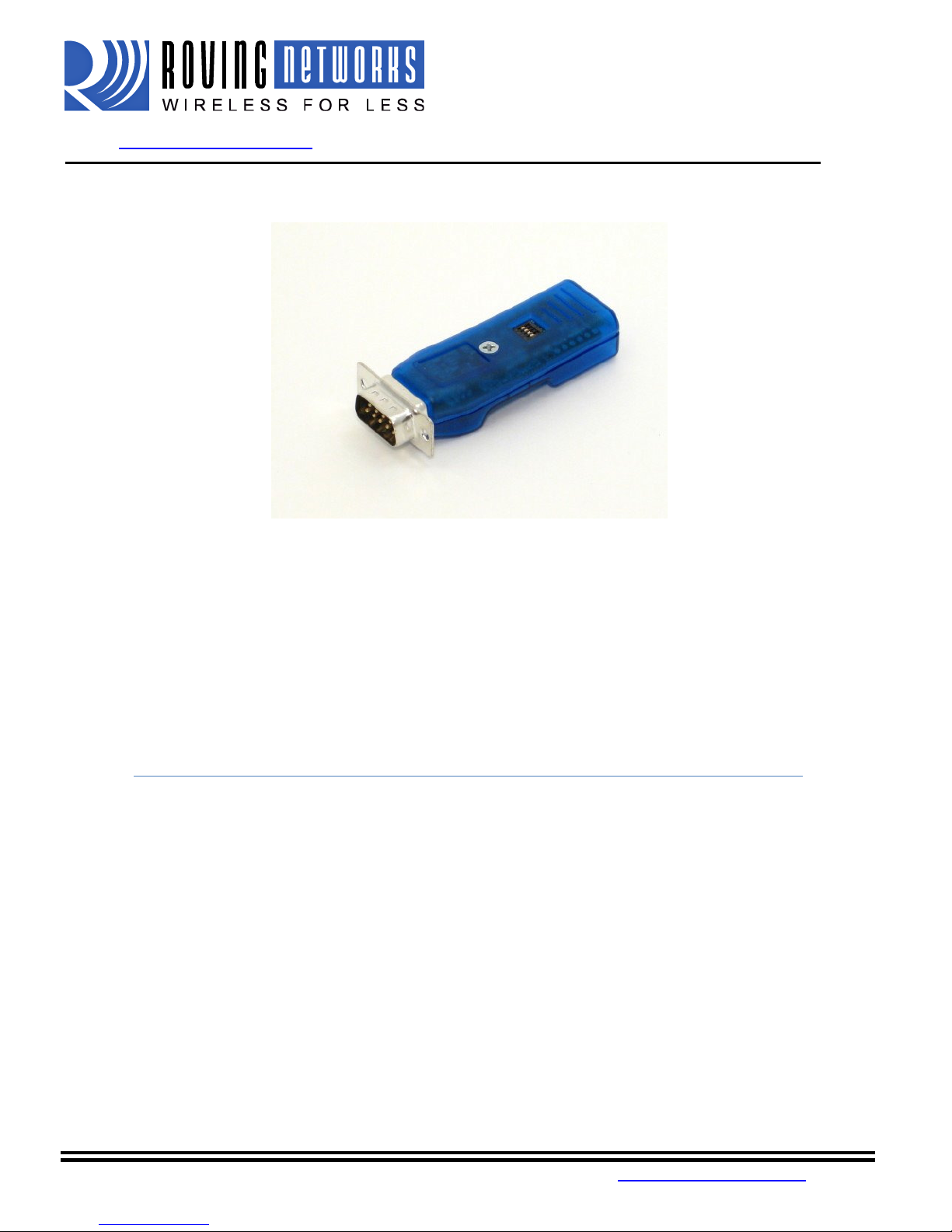
The FireFly serial adapter is compact, versatile Class 1 Bluetooth serial adapter. It enables wireless connections
to any legacy serial port and supports bi-directional RS232 or RS422 signaling at a rate of up to 464Kbps. Just
attach the FireFly to your device's RS232/EIA232/422 port, connect over Bluetooth, and you have a wireless cable
replacement solution. The transmit range can be up to 330' (100M), depending upon environmental factors.
FireFly Bluetooth adapter can be used as a Bluetooth Master or Slave device. The SPP connection to the unit
appears via a virtual COM interface. Data is sent and received on the client exactly as if a serial cable was
connected to a real COM port on the client.
FireFly can also be used in cable replacement mode where two Roving Networks Bluetooth devices are paired
using the configuration switches. The USB to Bluetooth (RN-USB-X) has pairing switches and can be used with
the FireFly BP to create a wireless connection to a PC without using the PC’s Bluetooth stack. For more
information on cable replacement, please refer to our “Cable Replacement Application Note” on the website.
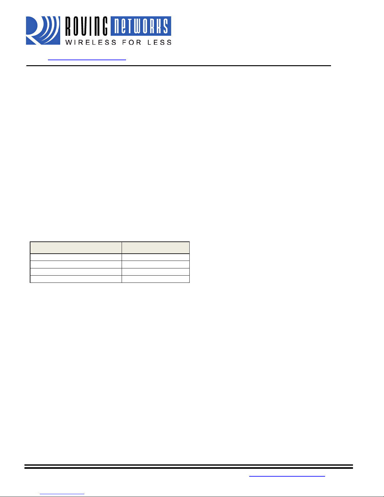
Status LEDs
The GREEN LED shows the Bluetooth connection status and the adapter operational mode. Upon boot up, it blinks
two times per second. In configuration mode, it blinks at a fat rate of ten times per second. When the module is in
discoverable or idle mode, the GREEN LED blinks one time per second. When the module is in connected sate, the
GREEN LED is solid ON.
MODE GREEN LED BLINK
In Configuration mode Fast, 10 x per second
Boot up, Remote Configurable 2 times per second
Discoverable/Idle 1 time per second
Connected On Solid
The yellow LED blinks when data is sent or received on the serial interface. This does not indicate that the data
was sent over the Bluetooth connection. If the yellow LED is not flashing when your device is sending data to the
serial port, you likely have the connection or flow control incorrectly set.
Some versions of RN-240 have a RED LED. This LED blinks when there is data being received over the RF link.
809 University Avenue • Los Gatos, CA 95032 • Tel (408) 395-6539 • info@RovingNetworks.com
~ 2 ~
Page 3
FireFly User Manual
www.rovingnetworks.com
RN-240-um Version 1.0 2/22/2010
Making a Bluetooth Connection
By default, the FireFly acts as a slave and the PC is the master. Connecting to the FireFly is done through the
Bluetooth device manager which has a different look and feel in Window CE, 2K, XP, Vista and Windows 7.
Regardless of the PC operating system, the process is essentially the same: Discovery, Pairing, and Connecting.
These processes are described below for a Windows 7 machine.
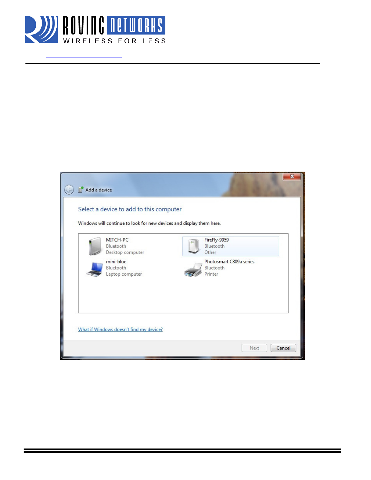
Discovery: The FireFly must be discoverable by simply turning it on. The Green LED should be blinking. On
your PC open the Bluetooth device manager and click on “Add” a new device. The Bluetooth device manager is
located in the bottom right corner of your screen in the taskbar. The Bluetooth device manager will display a list
of all the Bluetooth devices that are discoverable. The FireFly will be displayed as “FireFly-XXXX” where XXX is
the last 4 digits of the MAC address.
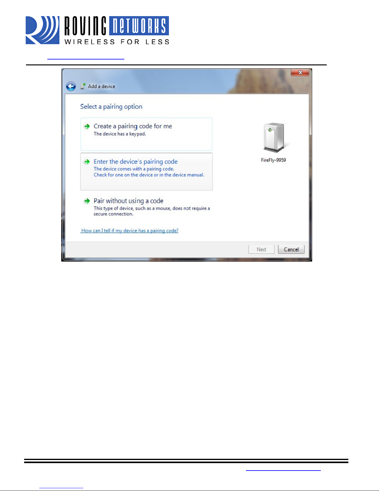
Pairing: Next you must pair with the device by double clicking on FireFly-XXXX in the list. Select “Enter the
device’s pairing code” option from the list. Enter the default pin code of 1234. Once the Bluetooth device
manager completes you will see a message to the effect, “Bluetooth device installed on COMX” where COMX is
unique to your machine. In some cases the Bluetooth device manager will create two COM ports, in this case you
only want to use the COM port labeled “outgoing”.
809 University Avenue • Los Gatos, CA 95032 • Tel (408) 395-6539 • info@RovingNetworks.com
~ 3 ~
Page 4
FireFly User Manual
www.rovingnetworks.com
RN-240-um Version 1.0 2/22/2010
You only need to pair with the FireFly once.
Connecting: To establish a Bluetooth connection, open up the COM port assigned to the device from either your
application or a terminal emulator. Once the COM port is open you will notice the green LED switches from
blinking to solid ON. The device will remain connected until the COM port is closed or the FireFly is turned off.
Pin Codes and Link Keys
If either the local or the remote Bluetooth device has authentication enabled, the following process occurs.
1. The first time a connection is attempted, a “passkey” is required. This is a series of numbers or
characters. (1234 is the default for the Roving Networks Bluetooth devices and modules)
2. Once this is entered, the remote Bluetooth device and local device compare their passkeys and if they
match, a link key is generated, and stored. Usually, but not always this is stored by the remote device.
3. Upon subsequent connections, the devices will first compare link keys and if they are correct, no pin code
will have to be re-entered.
If the remote device is a PC or PDA, a prompt is generally made to the user to enter this pincode. To remove the
stored link key on the remote device, generally you “unpair” or remove the device from the Bluetooth manager.
You can change the Pin Code to remove the link key on the FireFly. This will be forcing a new Pin Code exchange
process to occur upon subsequent connection attempts.
NOTE: Only one Master can connect to the FireFly at a time.
809 University Avenue • Los Gatos, CA 95032 • Tel (408) 395-6539 • info@RovingNetworks.com
~ 4 ~
Page 5

Los Gatos, CA 95032
The configuration switches on the top of the FireFly are small. You will need a paper clip or small screw driver to
change them. Hold the devices with the DB9 connector facing to the right, the switches are
four from bottom to top and the off position is towards the DB9 connector.
nd toggle the switch from ON
The GREEN LED flashes quickly for a moment and then continues to blink at about once per second.
In slave mode, sets a special class of device that is used the master to auto connect. If Switch 3 also ON, the
h, stores, and connects to a remote
connects to a stored remote address. First set the Bluetooth address of
and or through instant cable replacement settings.
OFF = 115K will be overridden by software baud rate configuration commands, ON = 9600 ignores any software
set using the “SM” command when in command mode. The possible
Default mode,
In this mode, the FireFly makes connections when a Connect Command “C”, is
received. This command can also contain the Bluetooth address of the remote device. If no device is
specified, then the store remote address is used. The connection can be broke
character or string is sent (use the SO command to set the break character)
In this mode, the FireFly makes connections automatically when a character is
received on the serial port. The connection will continue as long as characters are received on either end.
(which is set using the ST command)
XX (from 1 to 254) seconds of inactivity.
FireFly
Us
Version
info@RovingNetworks.com
to return the unit to factory
Roving Networks Bluetooth Device that
whereby other Bluetooth devices can discover and connect to the
n if the special break
This is a low speed
which will cause a disconnect after
er Manual
www.rovingnetworks.com
Configuration Switches
1 – RESTORE FACTORY DEFAULTS
Set this switch ON, power up unit, a
settings.
2 - AUTO DISCOVERY
device performs a searc
set.
3 - AUTO MASTER
Device acts as Bluetooth master, auto-
the slave device using the SR comm
4 - DEFAULT BAUD RATE
RN-240-um
-OFF-ON-OFF-ON
1.0 2/22/2010
numbered one to
has switch 2
configuration
Operating Modes
The operating modes for the FireFly are
operating modes are:
Slave (SM,1<CR>)
FireFly
Master (SM,1<CR>)
connect mode.
Trigger (SM,2<CR>)
There is a configurable timeout
809 University Avenue •
This is a low speed connect mode.
• Tel (408) 395-6539 •
~ 5 ~
Page 6

Los Gatos, CA 95032
In this mode, the FireFly makes connections automatically on powerup, and
connects when connection is lost. This
high speed connect mode, and cannot be broken by software break characters.
In all master modes the device will not be discoverable or allow configuration remotely over
pecification
RN
Female DB9
TXD
RXD
GND
CTS
RTS
12VDC
NOTE: The RS422 interface uses the MAX490 transceiver. This device is designed to operate with input voltage
RXD+ and TXD+ each have a 4.7K pull up to 5VDC.
each have a 4.7K pull down to GND.
interface uses the SIPEX SP3232ECA chip with capacitor switch to generate the + and
and thus is not driving the full RS232 voltages. Devices stealing power from the RS232 pins may not have enough
uration for the FireFly is
Serial port 115K baud rate, 8 bits, NP, 1 stop bit
Configuration is done by putting the FireFly into command mode and sending ASC
over the serial port or over the Bluetooth link.
Once you change the configuration parameters, they persist until changed or a factory reset is performed.
FireFly
Us
Version
info@RovingNetworks.com
mode can also be enabled by setting Dip Switch #2. This is the
II commands. This can be done
er Manual
www.rovingnetworks.com
Auto Master (SM,3<CR>)
re-
Bluetooth.
Serial Connector S
DB9 connector Pin Out
Pin
1 NC
2 RXD
3 TXD
4 NC
5 GND
6 NC
7 RTS
8 CTS
9 4-12VDC 4-
RN-240M
Male DB9
RN-240-um
-240F
NC NC
NC
RXD-
NC TXD+
GND
NC +5 VDC (input)
RXD+
TXD-
NC
1.0 2/22/2010
RN-422M
Male DB9
range of 4.75 to 5.25 VDC.
RXD- and TXD-
NOTE: The RS232
voltage
.
Device Configuration
The default config
• Bluetooth slave mode
• Bluetooth pin code 1234
•
• Serial port flow control disabled
• Low power mode off
– signals
809 University Avenue •
• Tel (408) 395-6539 •
~ 6 ~
Page 7

FireFly User Manual
www.rovingnetworks.com
Local configuration over the serial port
Connect the FireFly to the serial port your computer. You may need a null-modem cable (DB9 pins 2 and 3
swapped) if you have a RN-240M or a straight cable if you have a RN-240F. If your computer does not have a
serial port you can use a USB serial cable such as the RN-USB-SERIAL to connect the FireFLy to your computer.
With the FireFly connected and powered on, start your favorite terminal emulator and open the COM port that the
serial interface or serial USB is connected to. (A free terminal emulator, TeraTerm for the PC is available at
www.rovingnetworks.com/support/teraterm.zip)
The communication settings of the terminal emulator should match the default serial port settings of the FireFly
BP of 115,200Kbps, 8 bits, No Parity, 1 stop bit.
Remote Configuration over Bluetooth
NOTE:
Remote configuration can only occur if the bootup configuration timer (default 60 seconds) has not
expired. This timer is set to 0 (remote config disabled) for master mode, and auto-connect slave
mode, so that data can immediately flow between the 2 devices in cable replacement fashion.
You must first pair the Bluetooth device with your computer. Click on the “Bluetooth devices” icon in the system
tray at the bottom right of your computer. Select “Add a Bluetooth device”
Roving Netowrks recommends you download the free TeraTerm program from our website
(www.rovingnetworks.com/support/teraterm.zip), as we have found many bugs with Hyperterminal that render it
ineffective in talking to local serial ports.
RN-240-um Version 1.0 2/22/2010
Getting into command mode
Launch TeraTerm and make sure that the default settings are selected (115,200Kbps, 8 bits, No Parity, 1 stop
bit). You can change these settings by clicking on Setup Serial Port from within TeraTerm.
Type $$$ into the terminal emulator (3 dollar signs). You should see CMD returned to you. If you see CMD you
know that your connection and terminal settings are correct.
809 University Avenue • Los Gatos, CA 95032 • Tel (408) 395-6539 • info@RovingNetworks.com
~ 7 ~
Page 8

FireFly User Manual
www.rovingnetworks.com
Entering a valid command will return an AOK, invalid syntax returns ERR, and unrecognized commands will
return a ?. Type “h”<cr> to see a list of commands, and “d”<cr> to see a summary of current settings.
To return to data mode, type
“---“ ( 3 minus signs) <cr>, or reset the device and connect again.
RN-240-um Version 1.0 2/22/2010
Command Summary
All configuration information is stored in flash memory. The “set” command modifies the flash memory however
the Bluetooth module only reads the configuration from flash when powering up or after a reboot.
Some examples of common configuration commands:
SU,9600 sets Uart Baudrate to 9600
SN,myname sets Bluetooth name to “myname”
SA,1 enables secure authentication
SP,secret sets security pincode to “secret”
SF,1 restores all values to factory defaults
R,1 reboots the module
Set commands
S7,<1,0> 7 bit data mode. 1 to enable, 0 to disable. (setting can be seen with the “d” command).
SL,<E,O,N> Set UART parity. Can be any of, Even, Odd, or None. Only the first character is needed and
must be capital.
SU,<rate> Baudrate, {1200, 2400, 4800, 9600, 19.2, 28.8, 38.4, 57.6, 115K, 230K, 460K, 921K },
only the first 2 characters are needed.
SN,<name> Name of the device, 20 characters maximum. Example: “SN,MyDevice”
SS,<text> Service Name (1 to 20 characters ).
809 University Avenue • Los Gatos, CA 95032 • Tel (408) 395-6539 • info@RovingNetworks.com
~ 8 ~
Page 9

FireFly User Manual
www.rovingnetworks.com
S-,<name> Serialized Friendly Name of the device, 15 characters maximum. This command will
automatically append the last 2 bytes of the BT MAC address to the name. Example: S-
,MyDevice will set the name to “MyDevice-ABCD”
SC,<hex word> Service Class (four hex values, 11 bits used) this is used with Device Class command below
to create the 24 bit Class of Device number.
SD,<hex word> Device Class (four hex values, major and minor in a 16 bit word, used with service class
above)
To set the Class of Device (COD) to 0x1F0123 use the commands
SC,001F
SD,0123
SM,<5,4,3,2,1,0> Mode (0=slave, 1=master,2=trigger, 3=auto, 4=DTR, 5=ANY)
SR,<address> Store remote address, 12 hex digits, (6 bytes) no spaces or characters between digits
Example: SR,00A053112233 sets the remote Bluetooth address to 00A053112233
NOTE there are two special characters that can be used for the address parameter:
SR,Z will erase any stored address.
SR,I will write the last address seen using the inquiry command.
This can be helpful when you just have only one other device in range.
S?,<0,1> Role Switch. Enables and disables Role Switch. If set, when an incoming connection is
occurs to a slave mode device, an attempt will be made to force a role switch, allowing the
slave to become the master. This is useful in situations where high speed data is being sent
from the local device up to the remote host, and can result in better performance. However
this may create a situation whereby the connecting host will not be able to make additional
outbound connections (multipoint) while connected to this device. Default is DISABLED.
SE,<1,0> Encryption 1 to enable, 0 to disable.
SP,<text> Security pin code, 20 character maximum. Each time the device success pairs, the BT address
will be saved. Up to eight addresses can be stored on a first in first out bases. To erase all
stored pairings, reset the passkey command. You can use the same value that is already set.
ST,<number> Configuration timer, number of seconds (range= 0 to 255 decimal) to allow remote
configuration over Bluetooth after power up in Slave Mode. In all Master modes, the remote
configuration timer is set to 0 (no remote configuration). In Trigger Master Mode, the
configuration timer is used as an idle timer to break the connection after time expires with no
characters being received.
SW,<hex word> Enable low power SNIFF mode. See Low Power section
S|,<value> Low power connect mode.
S$,<char> Configuration detect character. This allows a change from the default $$$ to some other
VALUE
(decimal)
0 No remote config, No local config when
1-252 Time in seconds from power up to allow
253 Continous config LOCAL only
254 Contiuous config, REMOTE only
255 Continous config, both LOCAL and REMOTE
character.
RN-240-um Version 1.0 2/22/2010
DESCRIPTION
connected
config
809 University Avenue • Los Gatos, CA 95032 • Tel (408) 395-6539 • info@RovingNetworks.com
~ 9 ~
Page 10

FireFly User Manual
www.rovingnetworks.com
SF,1 Set Factory Defaults.
Display commands:
D Display basic settings.
E Display extended settings
O Display other settings
G<X> Display stored settings for command X. These commands correspond to the SET commands
above.
GB Returns the Bluetooth Address of the device.
GK Returns the current connection status: 1=connected, 0 = not connected.
V Return the software release version
Action Commands
+ Local echo. Toggle local echo of RX chars in command mode only. (default is off ).
C Attempt to connect to the REMOTE stored address.
C,<address> Connect to the address specified in hex format. The address is also stored as the REMOTE
address.
CF<address> Connect and immediately go into FAST data mode. NOTE: you will not be able to enter
command mode while connected. PIO6 can still be used to disconnect. Thus PIO6 should be
held HIGH before sending this command, as lowering PIO6 will cause a disconnect.
CFI Connect and immediately go into FAST data mode using the LAST address found from the
Inquiry command. NOTE: you will not be able to enter command mode while connected.
PIO6 can still be used to disconnect.
CFR Connect and immediately go into FAST data mode using the REMOTE address. Similar to the C
command but bypasses the configuration timer.
CT<address>,<timer> Connect with TIMER. The device will NOT use or store the remote address, rather will
make a connection to the <address> (REQUIRED). The device will automatically disconnect
after 7 seconds if no data is seen from UART or BT. An optional timer value can be entered to
change the timer. This value is in ¼ seconds. So for a 30 second timer, use 120 as the
value. The maximum value is 255 (64 seconds)
K, Kill (disconnect) from the current connection. The characters KILL<cr><lf> will be echoed to
the local UART once the connection is broken.
F,1 Go into fast data mode, ends configuration immediately.
H Help, will print out a list of commands and their basic syntax
R,1 Forces a complete reboot of the device (similar to a power cycle
RN-240-um Version 1.0 2/22/2010
809 University Avenue • Los Gatos, CA 95032 • Tel (408) 395-6539 • info@RovingNetworks.com
~ 10 ~
Page 11

Los Gatos, CA 95032
Instant Cable Replacement
Using two Roving Networks Bluetooth serial adapters or FirePlug (RN
each device as shown below.
Power up both devices and the master will discover the
The devices are now paired and the green LED on each device should be on solid.
After pairing, set switch 2 on both devices to OFF so that they don’t try to re
paired, every time the devices get in range of one another they will connect and the master will not attempt
To break this pairing restore the factor defaults using dip switch 1.
For more information on the instant cable replacement, please refer to the ‘Instant Cable Replacement Application
on off
FireFly
Us
Version
info@RovingNetworks.com
X) USB dongle, with the power OFF set
slave device, store its Bluetooth address and connect.
pair each time power is cycled.
on off
er Manual
www.rovingnetworks.com
the switches on
Master mode
Auto discovery and auto Master on
Once
to connect to any other Bluetooth device.
Master mode
4
3
2
1
RN-240-um
-USB-
Slave
Auto discovery on
-
Slave
1.0 2/22/2010
4
3
2
1
Note” posted on our website.
809 University Avenue •
• Tel (408) 395-6539 •
~ 11 ~
 Loading...