

Page 1
MANUFACTURING
NUMBERS:
9210318
9210319
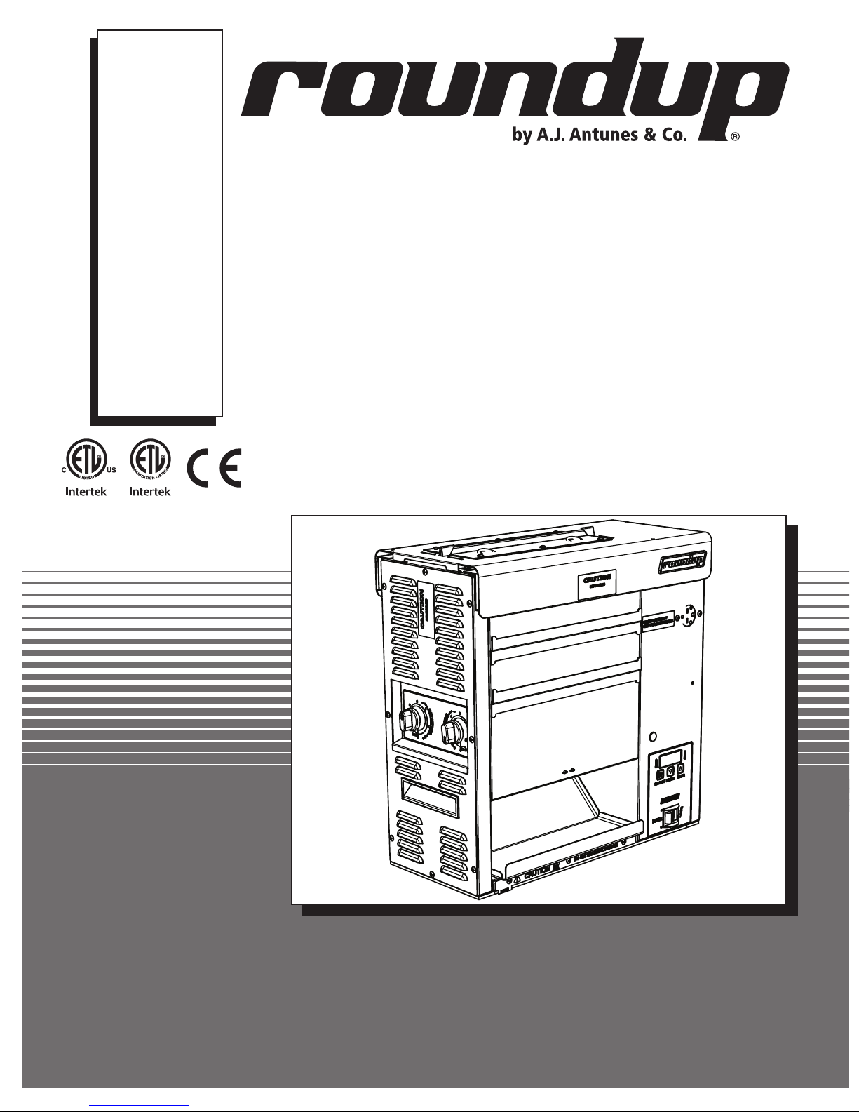
VERTICAL CONTACT
P/N 1011233 Rev. B 09/13
TOASTER
Model VCT-2010
Owner’s Manual
Page 2

VERTICAL CONTACT TOASTER
TABLE OF CONTENTS
Owner Information .....................................................2
General ......................................................................2
Warranty Information .................................................2
Service/Technical Assistance ....................................3
Specifications .............................................................5
Dimensions ................................................................5
Electrical Ratings .......................................................5
Electrical Cord & Plug Configurations .......................5
Installation ...................................................................7
Unpacking ..................................................................7
Equipment Setup .......................................................7
Assembling the Unit ..................................................7
Operation .....................................................................8
Operating Instructions ...............................................8
Light/Dark Adjustments ..............................................8
User Mode .................................................................9
Manager Mode ..........................................................9
Safety Features .......................................................10
OWNER INFORMATION
General
Fault Messages .......................................................10
Error Codes .............................................................10
Maintenance .............................................................. 11
Daily .........................................................................11
Replacing the Release Sheet (Every 3-5 Weeks) ...12
Replacing the Silicone Belts (Every 2–4 Months) ...13
About the VCT-2010 Clip Style Belt ........................13
Checking the Conveyor Belt Chains
(Every 3–6 Months) .................................................14
Checking the Roller Tensioners
(every 3–6 months) .................................................15
Troubleshooting .......................................................16
Replacement Parts ...................................................21
Wiring Diagram .........................................................25
VCT-2010 Clip Style Belt Instructions .....................26
Notes..........................................................................27
Limited Warranty ......................................................28
Warranty Information
The Vertical Contact Toaster Model VCT-2010 is
designed for contact toasting of buns. The toaster
design allows the operator to place buns on both sides
of the heated platen at the same time. Buns are placed
into the top of the toaster and uniform, golden brown,
warm buns are then retrieved at the base of the toaster.
This manual provides the safety, installation, and
operating procedures for the Vertical Contact Toaster
Model VCT-2010. We recommend that all information
contained in this manual be read prior to installing and
operating the unit.
Your Vertical Contact Toaster Model VCT-2010 is
manufactured from the finest materials available and
assembled to Roundup’s strict quality standards. This
unit has been tested at the factory to ensure dependable, trouble-free operation.
Please read the full text of the Limited Warranty in this
manual.
If the unit arrives damaged, contact the carrier immediately and file a damage claim with them. Save all
packing materials when filing a claim. Freight damage
claims are the responsibility of the purchaser and are
not covered under warranty.
The warranty does NOT extend to:
• Damages caused in shipment or damage as
result of improper use.
• Installation of electrical service.
• Normal maintenance as outlined in this manual.
• Malfunction resulting from improper maintenance.
• Damage caused by abuse or careless handling.
• Damage from moisture into electrical components.
• Damage from tampering with, removal of, or
changing any preset control or safety device.
IMPORTANT! Keep these instructions for future reference. If the unit changes
ownership, be sure this manual accompanies the equipment.
2
P/N 1011233 Rev. B 09/13
Page 3
VERTICAL CONTACT TOASTER
OWNER INFORMATION (continued)
Service/Technical Assistance
If you experience any problems with the installation
or operation of your unit, contact your local Roundup
Authorized Service Agency.
Fill in the information below and have it handy when
calling your Authorized Service Agency for assistance.
The serial number is on the specification plate located
on the rear of the unit.
Purchased From:
Date of Purchase:
Model No.:
Serial No.:
Mfg. No.:
Refer to the directory included with your unit or visit our
web site at www.ajantunes.com for a list of Authorized
Service Agencies.
Authorized Service Agency
Name:
Phone No.:
Address:
Use only genuine Roundup replacement parts in this
unit. Use of replacement parts other than those supplied by the manufacturer will void the warranty. Your
Authorized Service Agency has been factory trained
and has a complete supply of parts for this toaster.
You may also contact the factory at 1-877-392-7854
(toll free in the U.S.) or 630-784-1000 if you have trouble locating your Authorized Service Agency.
IMPORTANT
A.J. Antunes & Co. reserves the right to change specifications and product design
without notice. Such revisions do NOT entitle the buyer to corresponding changes,
improvements, additions, or replacements for previously purchased equipment.
P/N 1011233 Rev. B 09/13
3
Page 4

VERTICAL CONTACT TOASTER
IMPORTANT SAFETY INFORMATION
In addition to the warnings and cautions in this manual, use
the following guidelines to safely operate the unit:
• Read all instructions before using equipment.
• For your safety, the equipment is furnished with a
properly grounded cord connector. Do NOT attempt to
defeat the grounded connector.
• Install or locate the equipment only for its intended use
as described in this manual. Do NOT use corrosive
chemicals in this equipment.
• Do NOT operate this equipment if it has a damaged
power cord or plug, if it is not working properly, or if it
has been damaged or dropped.
• This equipment should be serviced by qualified personnel only. Contact the nearest Authorized Service
Agency for adjustment or repair.
• Do NOT block or cover any openings on the unit.
• Do NOT immerse the power cord or plug in water.
• Keep the power cord away from heated surfaces.
• Do NOT allow the power cord to hang over edge of a
table or counter.
The following warnings and cautions appear throughout
this manual and should be carefully observed:
• Failure to use Release Sheets may result in damage
to the equipment and loss of warranty coverage.
• Do NOT clean this appliance with a water jet.
• If the power cord is damaged, it must be replaced
by the manufacturer, its service agent, or a similarly
qualified person.
• All electrical connections must be in accordance
with local electrical codes and any other applicable
codes.
• WARNING, ELECTRICAL SHOCK HAZARD.
FAILURE TO FOLLOW THESE INSTRUCTIONS
COULD RESULT IN SERIOUS INJURY OR DEATH.
- Electrical ground is required on this appliance.
- Do NOT modify the power cord plug. If it does
not fit the outlet, have a proper outlet installed
by a qualified electrician.
- Do NOT use an extension cord with this unit.
- Check with a qualified electrician if you are
unsure if the appliance is properly grounded.
• Turn the power off, unplug the power cord, and
allow unit to cool down before performing any
service or maintenance.
• The toaster should be grounded according to local
electrical codes to prevent the possibility of electrical shock. It requires a grounded receptacle with
separate electrical lines protected by fuses or a
circuit breaker of the proper rating.
• Bread may burn. Therefore toasters must NOT be
used near or below curtains or other combustible
walls and materials. Failure to maintain safe
operating distances may cause discoloration or
combustion.
• When installing a Silicone Belt, do NOT install
it around the Upper and Lower Support Rods or
permanent damage to the Silicone Belt will occur.
Make sure the Silicone Belt is only installed around
the Conveyor Belt Chain.
• Make sure both ends of the Silicone Belt are
aligned before installing the Silicone Belt Pin.
4
P/N 1011233 Rev. B 09/13
Page 5
VERTICAL CONTACT TOASTER
SPECIFICATIONS
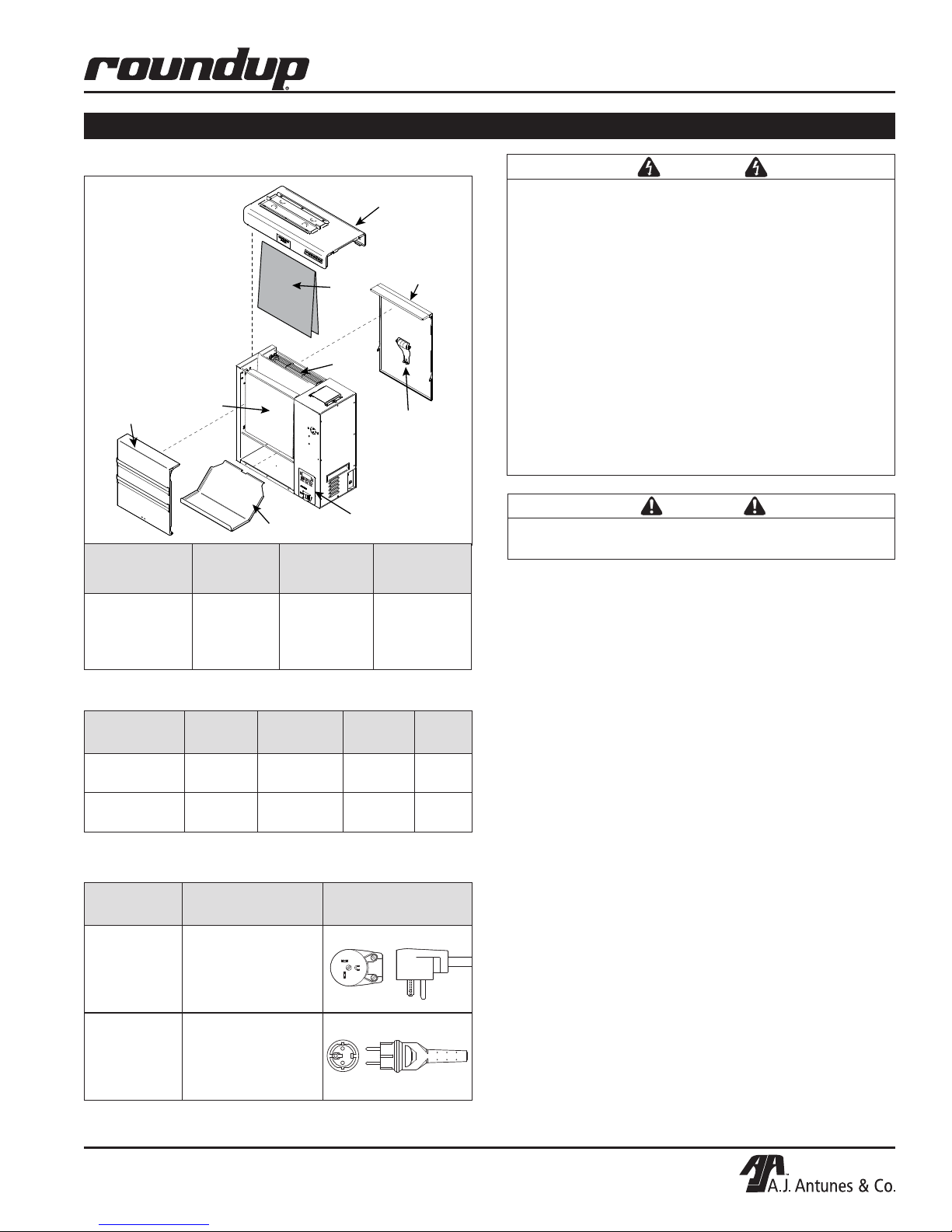
Dimensions
Conveyor
Cover (Front)
Model &
Mfg. No.
Silicone
Belt
Width
(A)
Bun Chute
Release
PROGRAM
LIGHTER
DARKER
Depth
(B)
Heat Shield
Sheet
Conveyor
Belt
Chain
Control Panel
and Power Switch
Conveyor
Cover (Rear)
Roller
Tensioner
Height
(C)
WARNING
ELECTRICAL SHOCK HAZARD. FAILURE TO FOLLOW
THE INSTRUCTIONS IN THIS MANUAL COULD RESULT
IN SERIOUS INJURY OR DEATH.
• Electrical ground is required on this appliance.
• Do NOT modify the power cord plug. If it does not fit
the outlet, have a proper outlet installed by a qualified electrician.
• Do NOT use an extension cord with this appliance.
• The toaster should be grounded according to local
electrical codes to prevent the possibility of electrical
shock. It requires a grounded receptacle with separate
electrical lines protected by fuses or a circuit breaker
of the proper rating.
• Check with a qualified electrician if you are unsure if
the appliance is properly grounded.
CAUTION
Failure to use Release Sheets may result in damage to
the unit and loss of warranty coverage.
VCT-2010
9210318
9210319
20”
(508 mm)
15 1/4”
(387 mm)
(508 mm)
Electrical Ratings
Model &
Mfg. No.
VCT-2010
9210318
VCT-2010
9210319
Volts Watts Amp. Hz.
208 3300 15.8 50/60
230 3300 14.4 50/60
Electrical Cord & Plug Configurations
Model &
Mfg. No.
VCT-2010
9210318
VCT-2010
9210319
Description Configuration
Power Cord
Assembly
20 Amp, 250 Volt
Right Angle
16 Amp, 250 Volt
CEE 7/7 Plug
20”
P/N 1011233 Rev. B 09/13
5
Page 6
VERTICAL CONTACT TOASTER
SPECIFICATIONS (continued)
Release
Sheet
Heat Shield
Conveyor
Cover (Rear)
Conveyor
Cover (Front)
Silicone
Belt
PROGRAM
LIGHTER
DARKER
Bun Chute
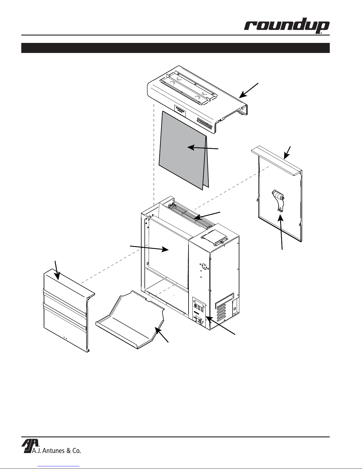
Figure 1. VCT-2010 Vertical Contact Toaster
Conveyor
Belt
Chain
Roller
Tensioner
Control Panel
and Power Switch
6
P/N 1011233 Rev. B 09/13
Page 7
VERTICAL CONTACT TOASTER
INSTALLATION
Unpacking
1. Remove the unit and all packing materials from
the shipping carton.
2. Open the Accessories Box. It should contain the
following:
• Bun Chute
• Two Release Sheets
• Owner’s Manual
• Authorized Service Agency Directory
3. Remove all shipping tape and protective coverings from the unit and parts.
NOTE: If any parts are missing or damaged,
contact Antunes Technical Service IMMEDIATELY at
1-877-392-7854 (toll free in the U.S.) or 630-784-1000.
Equipment Setup
Before placing the toaster into service, pay attention to
the following guidelines:
• Make sure power is off and the toaster is at room
temperature.
• Do NOT block or cover any openings on the unit.
• Do NOT immerse the power cord or plug in water.
• Keep the power cord away from heated surfaces.
• Do NOT allow the power cord to hang over the
edge of a table or counter.
• Connect the unit to the proper power supply.
Refer to the specification plate for the proper
voltage.
CAUTION
Bread may burn. Therefore toasters must NOT be
used near or below curtains or other combustible
walls and materials. Failure to maintain safe
operating distances may cause discoloration or
combustion.
Assembling the Unit
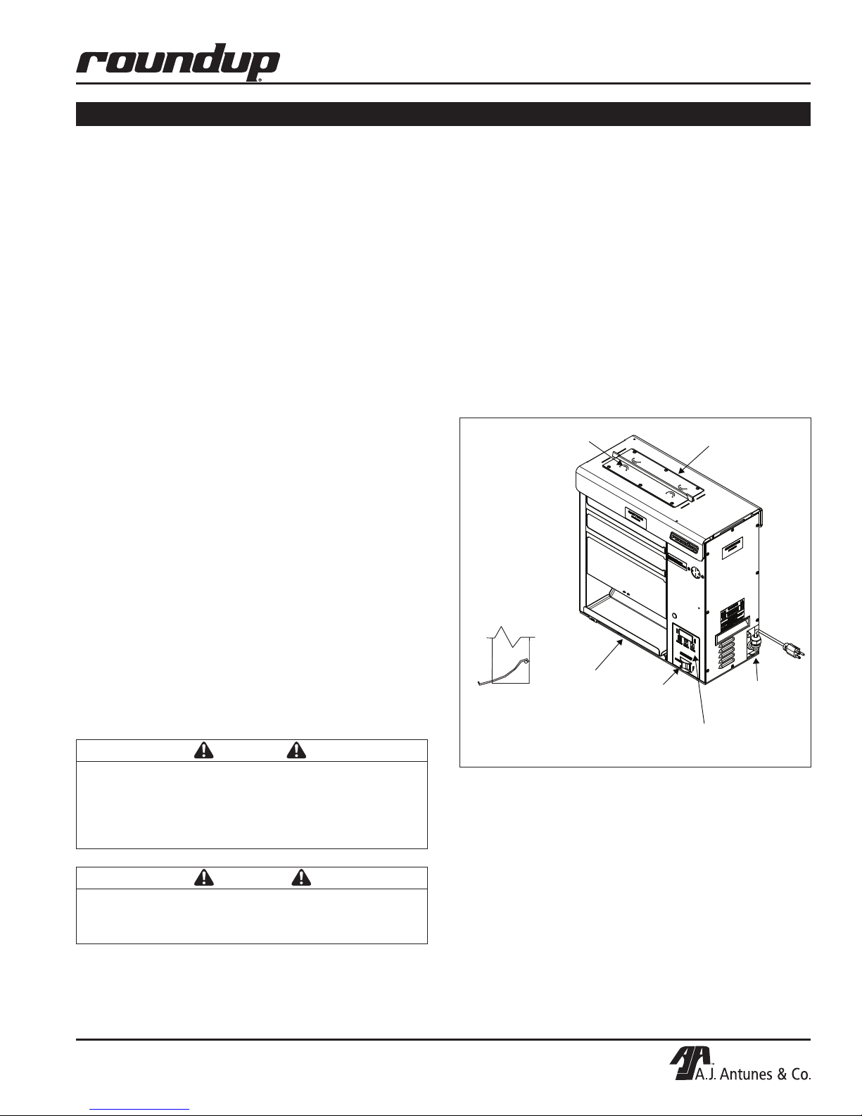
NOTE: The factory has pre-installed a Release
Sheet over the Platen (Figure 1). Verify that it is
properly in place before proceeding.
1. Place the unit on a flat, sturdy location.
2. Install the Bun Chute so the hooks are installed
over the lower rear yellow Support Rod (Figure 2).
IMPORTANT: Do NOT plug any other power cords
into the receptacles on the toaster.
NOTE: Make sure the Heat Shield is activating the
Conveyor Safety Interlock Switch. The unit will not
function unless the Heat Shield is in place and the
Conveyor Safety Interlock Switch is activated.
Side view of
Bun Chute connected
over the bottom
rear support rod
Figure 2. VCT-2010 Components
Crown Side
Bun Chute
Power
Switch
Temperature Controls &
Heel Side
Hi-Limit
Control
Temperature Display
CAUTION
All electrical connections must be in accordance
with local electrical codes and any other applicable codes.
P/N 1011233 Rev. B 09/13
7
Page 8
VERTICAL CONTACT TOASTER
Hi-Limit
Control
Temperature Controls &
Temperature Display
Power
Switch
Bun Chute
Bun Thickness
Adjustment Controls
(Side of Unit)
Heel Side
Crown Side
OPERATION
Operating Instructions
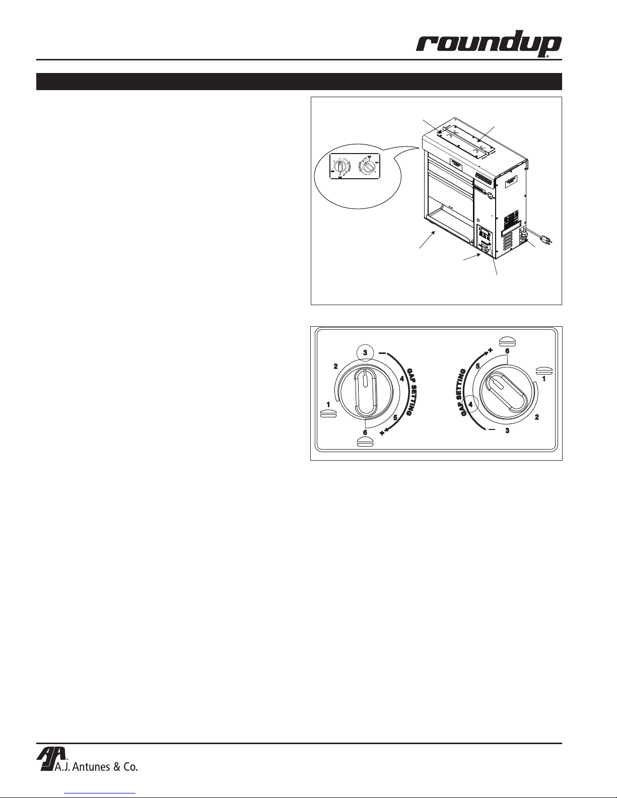
NOTE: The unit includes Bun Thickness Adjustment
Controls (Figure 4), which are factory set to #3 for
Heels and #4 for Crowns.
NOTE: Recommended settings are #3 for Heels and
#4 for Crowns.
1. Turn the power on and allow the unit to warm up
for 30 minutes before proceeding.
NOTE: The temperature display (Figure 3) flashes
“LO” until the toaster reaches its preset operating
temperature. When the toaster approaches the preset
temperature of 570°F (299°C), “USE” appears in the
temperature display and the unit is ready to toast
buns. If “USE” does not appear in the window after
approximately 30 minutes, contact your Authorized
Service Agency.
3. Drop Crowns and Heels into the slot (Figure 3).
Figure 3. VCT-2010 Toaster
NOTE: The cut side of the Heels and Crowns must
face each other.
4. Toasted buns will drop out of the unit and down
the Bun Chute (Figure 3) in approximately 18
seconds.
5. Test at least 4 buns before putting the toaster into
service.
6. Turn the power off for the unit when finished
toasting for the day. Then proceed with the Daily
Cleaning as outlined in the Maintenance section of
this manual.
Figure 4. Bun Thickness Adjustment Controls
Light/Dark Adjustments
The light/dark value can be adjusted when the unit is
displaying “LO” or “USE”. To adjust the light/dark value,
press the LIGHTER or DARKER button. The display
will change to show the current light/dark value.
NOTE: The default light/dark value is d0.
Press the LIGHTER or DARKER button to change the
light/dark value. The adjustment range is L1-L9 and
d0-d9. L9 is the lightest, d0 is the middle, and d9 is the
darkest setting.
To save the light/dark value, press the PROGRAM button
or wait 5 seconds until the screen displays “LO” or “USE”.
NOTE: Adjusting the light/dark value does NOT
change the temperature. It changes the speed of the
conveyors. The light/dark value will reset to the d0
value when the unit is turned off.
8
P/N 1011233 Rev. B 09/13
Page 9
OPERATION (continued)
User Mode
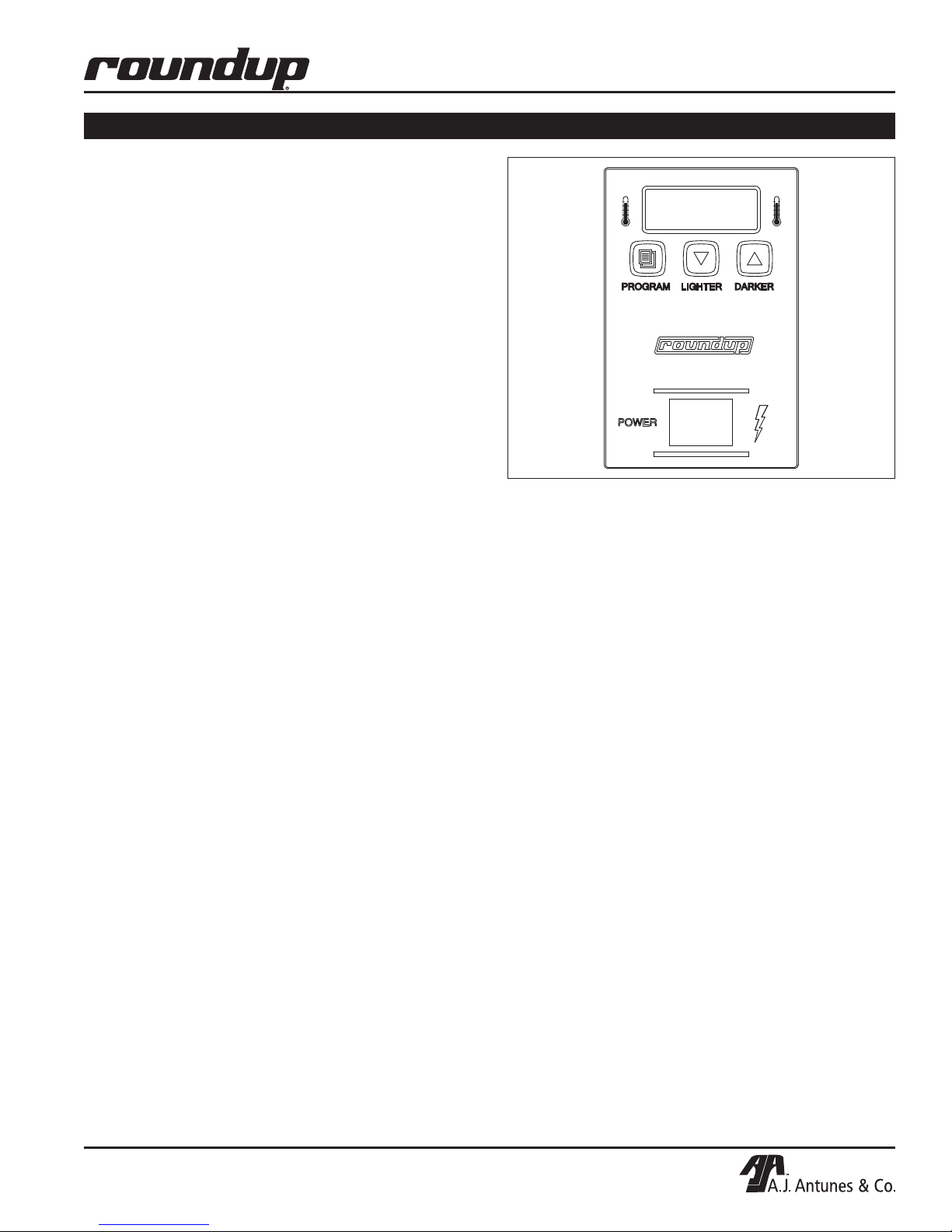
User Mode allows an operator to view the toaster settings but does not permit any adjustments.
1. Press and hold the PROGRAM button for 5 seconds.
After 5 seconds, the display will show the actual
temperature of the Platen Heater.
2. Press the LIGHTER button to view the setpoint of
the Platen Heater.
3. Press the PROGRAM button to proceed to the
Auxiliary Heater menu. The display will show the
actual temperature of Auxiliary Heater.
4. Press the LIGHTER button to view the setpoint of
the Auxiliary Heater.
5. Press the PROGRAM button to proceed to the
Motor Menu. The display will show the actual
speed of the Motor.
VERTICAL CONTACT TOASTER
PROGRAM
Figure 5. VCT-2010 Toaster Control Panel
LIGHTER
DARKER
6. Press the LIGHTER button to view the setpoint of
the Motor.
NOTE: The unit will exit User Mode after 5 seconds
of keypad inactivity.
Manager Mode
Manager Mode allows an operator to view and adjust
the following settings:
• Platen Heater Temperature
• Auxiliary Heater Temperature
• Motor Speed
• Temperature Units
Manager Mode also allows an operator to view (but
not adjust) the Ambient Temperature of the Control
Compartment.
1. Turn the unit off.
2. Turn the power on while holding the PROGRAM
button. Continue to hold the button until “ENA”
appears on the display (after approximately 10
seconds).
3. Release the PROGRAM button. The display now
shows the Platen Setpoint Temperature.
4. To adjust the Platen Setpoint, press the LIGHTER
or DARKER buttons to reach the desired temperature.
NOTE: The recommended temperature setting for
the Platen Heater is 570°F (299°C).
5. Press the PROGRAM button to proceed to the
Auxiliary Heater Setpoint Temperature.
6. To adjust the Auxiliary Heater Setpoint, press
the LIGHTER or DARKER buttons to reach the
desired temperature.
NOTE: The recommended temperature setting for
the Auxiliary Heaters is 330°F (166°C).
7. Press the PROGRAM button to proceed to the
Motor Speed Setpoint.
8. Adjust the Motor Speed Setpoint by pressing
the LIGHTER or DARKER buttons to reach the
desired speed.
NOTE: The Motor Speed is adjustable from 1-100.
The recommended setting is 52.
9. Press the PROGRAM button to proceed to
Temperature Units.
10. To change the Temperature Units from Fahrenheit or
Celsius, press the LIGHTER or DARKER buttons.
11. Press the PROGRAM button to proceed to the
Ambient Temperature of the Control Compartment.
NOTE: No changes can be made to the Ambient
Temperature of the Control Compartment.
Temperatures under 150°F (66°C) are acceptable.
12. Press and hold the PROGRAM button to save
any changes.
NOTE: The unit will exit Manager Mode after 30
seconds of keypad inactivity.
P/N 1011233 Rev. B 09/13
9
Page 10
VERTICAL CONTACT TOASTER
OPERATION (continued)
Safety Features
HI-LIMIT CONTROL
A Hi-Limit Control turns off electrical power to the
heaters and control circuits if the unit overheats. To
reset the control, allow 10-15 minutes for the unit to
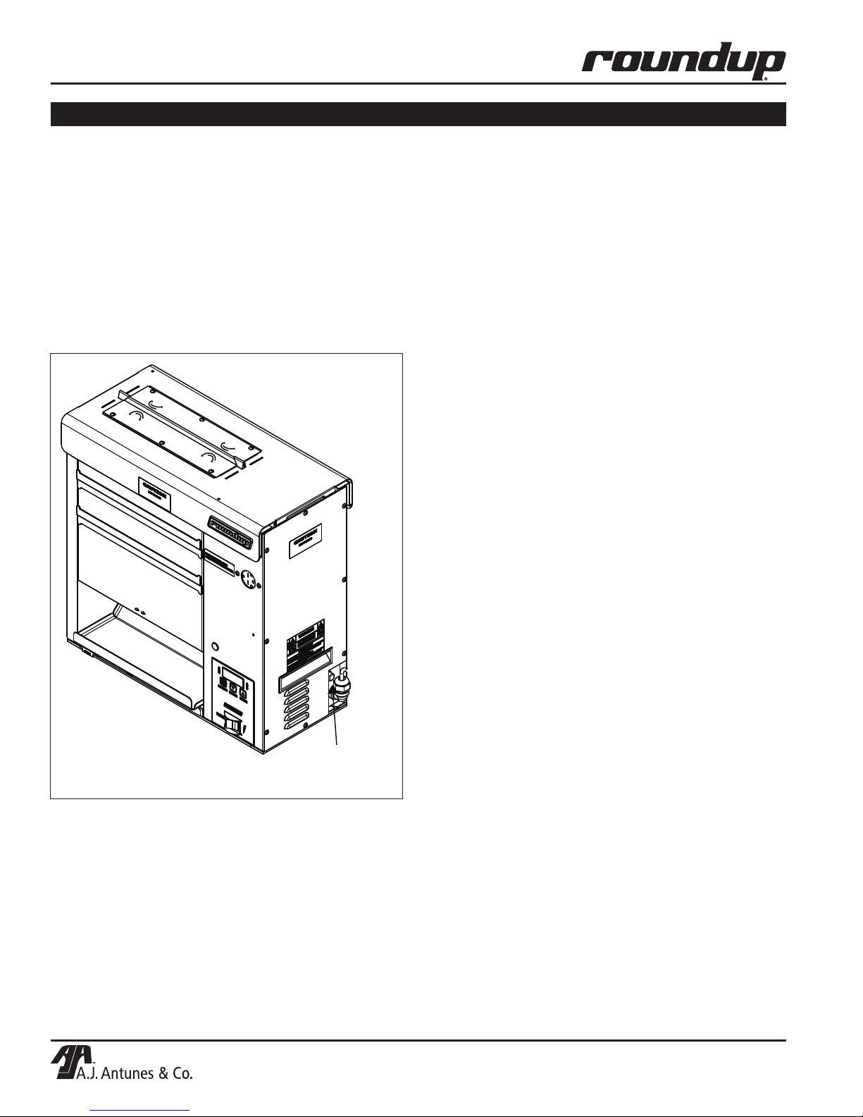
cool, then locate the Hi-Limit Control (Figure 6) on
the side of the unit. Remove the black protective cap,
press the button, and reinstall the protective cap.
NOTE: If the Hi-Limit Control requires continuous
resetting, contact your Authorized Service Agency.
Fault Messages
The Control Display will flash fault messages when
there is a problem with the unit.
“HI” will flash if the Platen Heater temperature is 30°F
more than the setpoint or if the Platen Thermocouple is
disconnected or open.
“HI” and “USE” will flash if the Auxiliary Heater
temperature is 50°F more than the setpoint or if the
Auxiliary Thermocouple is disconnected or open.
“CHEC” will flash when the control compartment ambient temperature is more than 150°F (66°C). All heaters
will shut off. The unit will not restart until the control
compartment ambient temperature falls below 140°F
(60°C).
“PO” will flash if the incoming power drops below 190
Volts. The toaster will shut down.
“StoP” will flash when the motor has stopped for seven
continuous seconds.
“SpEd” will flash when the motor speed has dropped
25% below the setpoint for 30 continuous seconds.
Error Codes
Figure 6. Hi-Limit Control
Hi-Limit
Control
If any of the following Error Codes appear, turn the
power off, allow the unit to cool, and turn the power
back on. If the error repeats, contact your Authorized
Service Agency for assistance.
ERR 1: Internal error. Cycle the Power Switch. If error
persists, replace the board.
ERR 2: Internal error. Cycle the Power Switch. If error
persists, replace the board.
ERR 3: Internal error. Cycle the Power Switch. If error
persists, replace the board.
ERR 4: Invalid DIP Switch setting. The only approved
setting is (left to right) up-up-up-down (1 on; 2,
3, 4 off).
ERR 5: Internal error. Cycle the Power Switch. If error
persists, replace the board.
ERR 6: Internal error. Cycle the Power Switch. If error
persists, replace the board.
ERR 7: Not used.
ERR 8: Shorted Platen Thermocouple.
ERR 9: Open Platen Thermocouple.
10
P/N 1011233 Rev. B 09/13
Page 11
VERTICAL CONTACT TOASTER
MAINTENANCE
WARNING
Turn the power off, unplug the power cord, and let
the unit cool down for 30 minutes before starting
any service or maintenance.
CAUTION
To prevent damage to the unit, do NOT use abrasive cleaners on Release Sheet or Silicone Belt.
Daily
AT CLOSE
• Turn the unit OFF and unplug the power cord.
Allow unit to cool.
AT OPEN
• Make sure unit is off and unplugged at the outlet.
• Take Heat Shield off; then, remove Release
Sheets.
• Fill a full-sized pan with hot Detergent Solution and
place both Release Sheets into pan to soak.
• Remove Heat Shield, Front and Back Conveyor
Covers, and Bun Chute and take to dishwashing
sink.
NOTE: Do NOT place parts into the powerwash
sink.
• Pre-rinse, hand wash, rinse and sanitize parts.
Return parts to service line.
• Remove Release Sheets that have been soaking
and take to dishwashing sink. Hand wash, rinse,
and sanitize both sides. Return to service line.
• Wipe outside of toaster with a clean, white towel
and hot Detergent Solution.
• Reinstall the Bun Chute and Front and Back
Conveyor Cover.
• Install the Release Sheet. NOTE: Rotate sheet
daily from silver to black side.
• Install the Heat Shield. Plug unit in.
• Turn toaster ON 30 minutes prior to opening.
NOTE: Line 2 toaster in modern restaurants can be
cleaned during slow periods of the day.
NOTE: Make sure the Heat Shield is activating the
Conveyor Safety Interlock Switch. The unit will not
function unless the Heat Shield is in place and the
Conveyor Safety Interlock Switch is activated.
NOTE: Check the Release Sheet to make sure it is
not caught in the Conveyor. Additional Release
Sheets can be purchased under P/N 7000625
(3-Pack).
CAUTION
Failure to use Release Sheets may result in damage
to the unit and loss of warranty coverage.
• Fill a clean 1/6-sized, 6-inch deep s/s pan with
hot Detergent Solution; a second pan with clean
rinse water; and a third pan with Sanitizer Solution.
Place a clean, white towel in each pan and place
near toaster.
• Wipe both sides of the Silicone Belts (side facing out first) with a clean, white towel and hot
Detergent Solution. Rinse with a clean, white towel
and clean rinse water. Sanitize using a clean, white
towel and Sanitizer Solution.
• Rotate Belt around so the side facing inward is facing out, exposing the soiled areas of the Silicone
Belt. Wash, rinse, and sanitize following the above
step.
P/N 1011233 Rev. B 09/13
11
Page 12
VERTICAL CONTACT TOASTER
INCORRECT
CORRECT
MAINTENANCE (continued)
Replacing the Release Sheet (Every 3-5
Weeks)
NOTE: Depending on toaster usage and how well
it is cleaned daily, the Release Sheet should last 3
to 5 weeks. Additional Release Sheets can be purchased under P/N 7000625 (3-Pack).
1. Turn the power off to the unit. Unplug the power
cord.
2. Put on heat-resistant gloves and remove the
Heat Shield (Figure 7).
3. Remove and discard the Release Sheet.
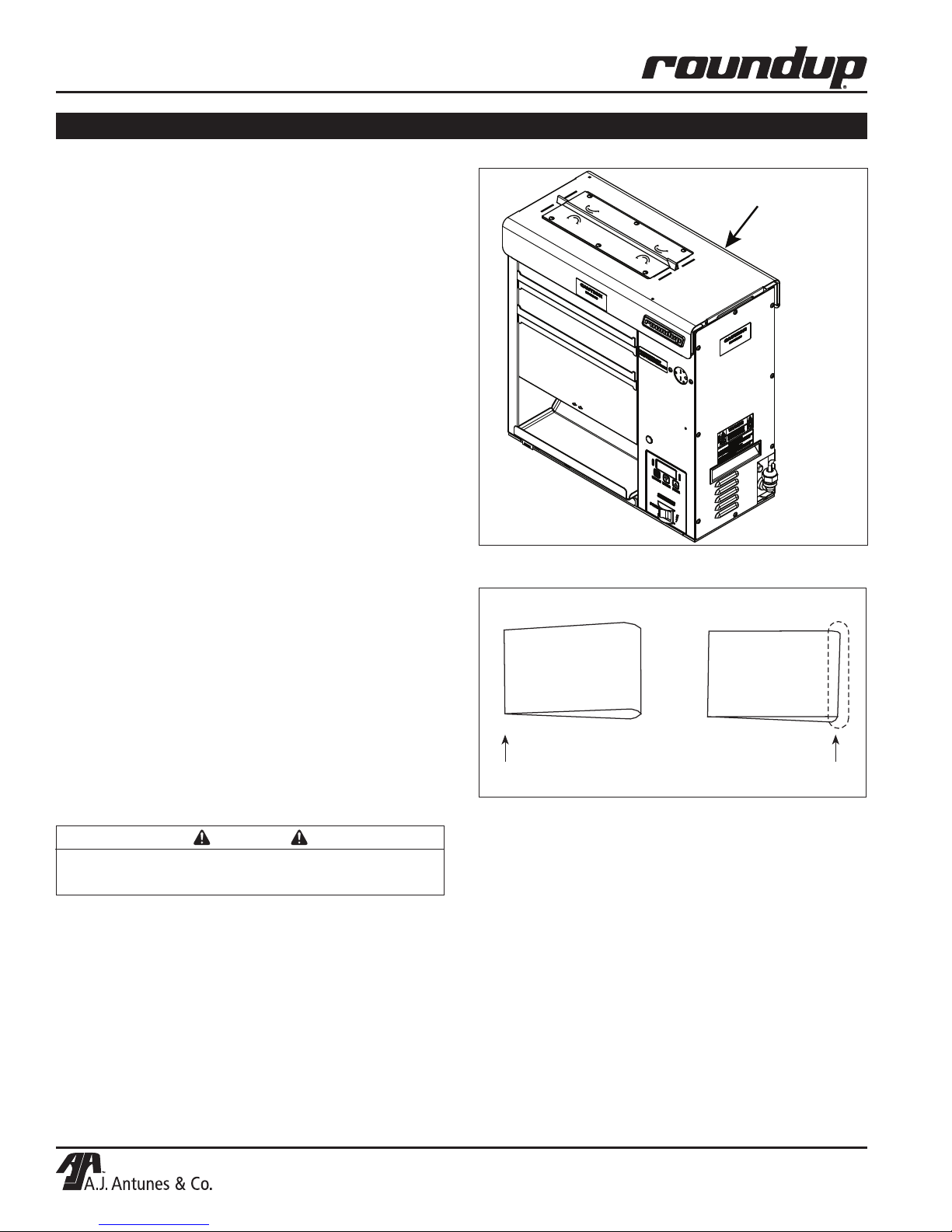
4. Lay a new Release Sheet on a clean, dry surface
and fold it in half lengthwise. Then gently crease it
at the fold using only your fingers (Figure 8).
5. Install the new Release Sheet by draping it over
both sides of the Platen with the crease centered
on the Platen.
6. Reinstall the Heat Shield with the Release Sheet
retainer clips securely over the Release Sheet
and Platen.
Heat Shield
Figure 7. Heat Shield
7. Plug in the power cord and test the unit before
returning it to service.
NOTE: Make sure the Heat Shield is activating the
Conveyor Safety Interlock Switch. The unit will not
function unless the Heat Shield is in place and the
Conveyor Safety Interlock Switch is activated.
NOTE: Check the Release Sheet to make sure it is
not caught in the Conveyor.
CAUTION
Failure to use Release Sheets may result in damage to the unit and loss of warranty coverage.
Fold over so
ends meet.
Figure 8. Folding the Release Sheet
Press lightly with
finger to form crease.
12
P/N 1011233 Rev. B 09/13
Page 13
MAINTENANCE (continued)
INCORRECT
CORRECT
Silicone
Belt Pin
Silicone Belt
Flap (down)
Silicone
Belt
Replacing the Silicone Belts (Every 2–4
Months)
NOTE: Depending on toaster usage and how well
it is cleaned daily, the Silicone Belts should last 2
to 4 months. Additional Silicone Belts may be purchased under P/N 7000898 (2-Pack).
1. Turn the power off, unplug the power cord, and
allow the unit to cool.
2. Set the Bun Thickness Compression Knobs to 6
and 6.
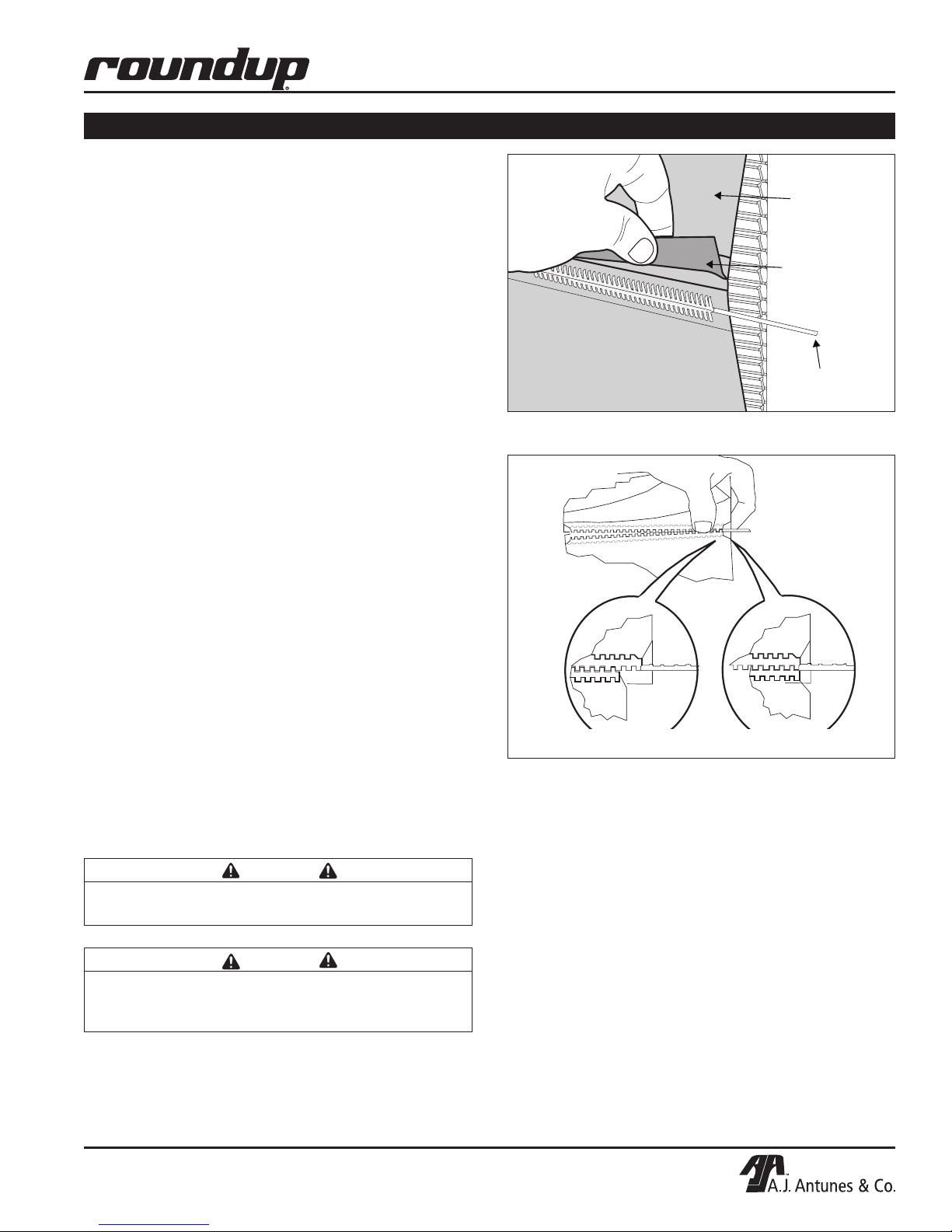
3. Remove the front and rear Conveyor Covers and
pull the Silicone Belt Pins out of the zipper on the
Silicone Belts (Figure 9).
4. Remove and discard the old Silicone Belts.
5. Clean both Conveyor Belt Chains as you would
clean the Silicone Belts during Daily Cleaning.
6. Install new Silicone Belts around the Conveyor
Belt Chains between the yellow Upper and Lower
Support Rods. The zipper flap should be exposed
and hanging down (Figure 9).
NOTE: Make sure the Silicone Belt is only installed
around the Conveyor Belt Chain.
7. Install the Silicone Belt Pins in the new Silicone
Belts, ensuring the ends are properly aligned
(Figure 10).
8. Set the Bun Thickness Compression Knobs to 3
and 4.
9. Reinstall the front and rear Conveyor Covers.
10. Reinstall the Heat Shield.
11. Plug in the power cord and test the unit before
returning it to service.
VERTICAL CONTACT TOASTER
Figure 9. Removing Silicone Belt
Figure 10. Aligning Belt Teeth
About the VCT-2010 Clip Style Belt
CAUTION
Align the ends of the Silicone Belt properly
(Figure 10) or the Silicone Belt may be damaged.
CAUTION
Position the Silicone Belt between the yellow
Upper and Lower Support Rods or the Silicone
Belt may be damaged.
P/N 1011233 Rev. B 09/13
The VCT-2010 Silicone Belts have been updated to
clip onto the wire conveyor belts and connect together
using the standard belt pin.
For information on installing these new style belts, refer
to Page 26 for complete instructions.
13
Page 14
VERTICAL CONTACT TOASTER
MAINTENANCE (continued)
Checking the Conveyor Belt Chains
(Every 3–6 Months)
NOTE: The Bun Thickness Compression Knobs
(Figure 4) must be set to 6 and 6 prior to measuring,
removing or reinstalling the Conveyor Belt Chains.
MEASURING CONVEYOR BELT CHAINS
1. Remove the Bun Chute and Heat Shield (Figure
1). Set the Bun Thickness Compression Knobs to
6 and 6.
2. Remove both Conveyor Covers and pull the
Silicone Belt Pin out of the zipper (Figure 9).
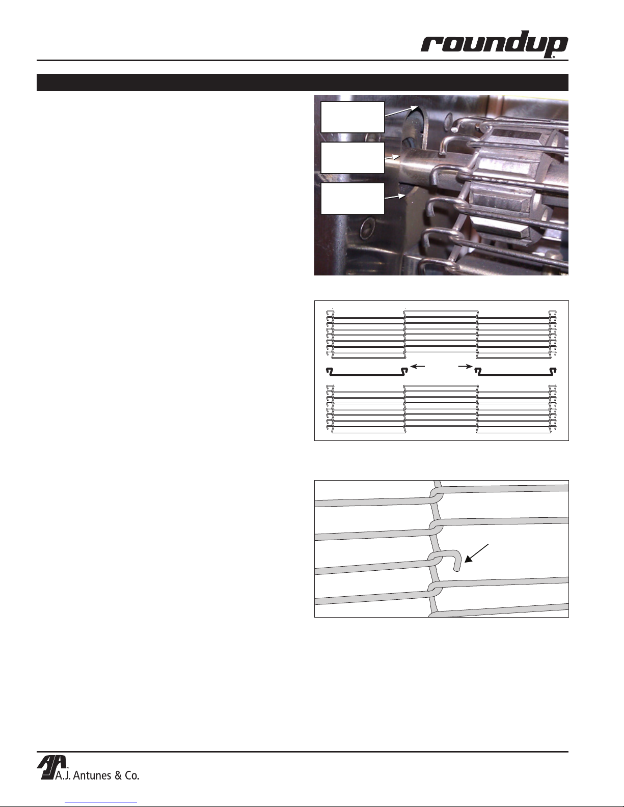
3. See Figure 11. With the belt wraps removed,
locate the top Idler Shafts for the front and rear
conveyors. There is an oval cut-out on the chassis of the unit. The top Idler Shafts should be in
the middle of the oval cut out or lower. If the shaft
is higher, remove a link from the conveyor chain.
In the example shown, a link does NOT need to
be removed.
REMOVING CONVEYOR BELT CHAIN LINKS
1. Turn the power off, unplug the power cord, and
allow the unit to cool.
2. Remove the Bun Chute and Heat Shield. Set the
Bun Thickness Compression Knobs to 6 and 6.
3. Remove the Conveyor Cover(s) and pull the
Silicone Belt Pin out of the zipper. Remove the
Silicone Belt(s).
4. Locate the two Master Links (Figure 12).
5. Remove the Master Link on both the left and right
side of the chain.
6. Remove one complete link from the chain.
7. Replace the Master Links on both the left and
right side of the chain. This connects the two
ends of the chain together.
NOTE: The ends of the Master Links must point
down (Figure 13).
8. Replace the Silicone Belt(s). Secure with the
Silicone Belt Pin.
NOTE: Make sure the Conveyor Belt Chain and
Silicone Belt are installed between the yellow
Upper and Lower Support Rods.
9. Reinstall the Conveyor Cover(s), Bun Chute, and
Heat Shield.
Top of Oval
Cut-out
Middle of Oval
Cut-out
Bottom of
Oval Cut-out
Figure 11. Measuring Conveyor Belt Chain
Master
Links
Figure 12. Conveyor Belt Chain
Master Link
Figure 13. Removing Conveyor Belt Chain
10. Set the Bun Thickness Compression Knobs to 3
and 4. Return the unit into service.
14
P/N 1011233 Rev. B 09/13
Page 15
VERTICAL CONTACT TOASTER
MAINTENANCE (continued)
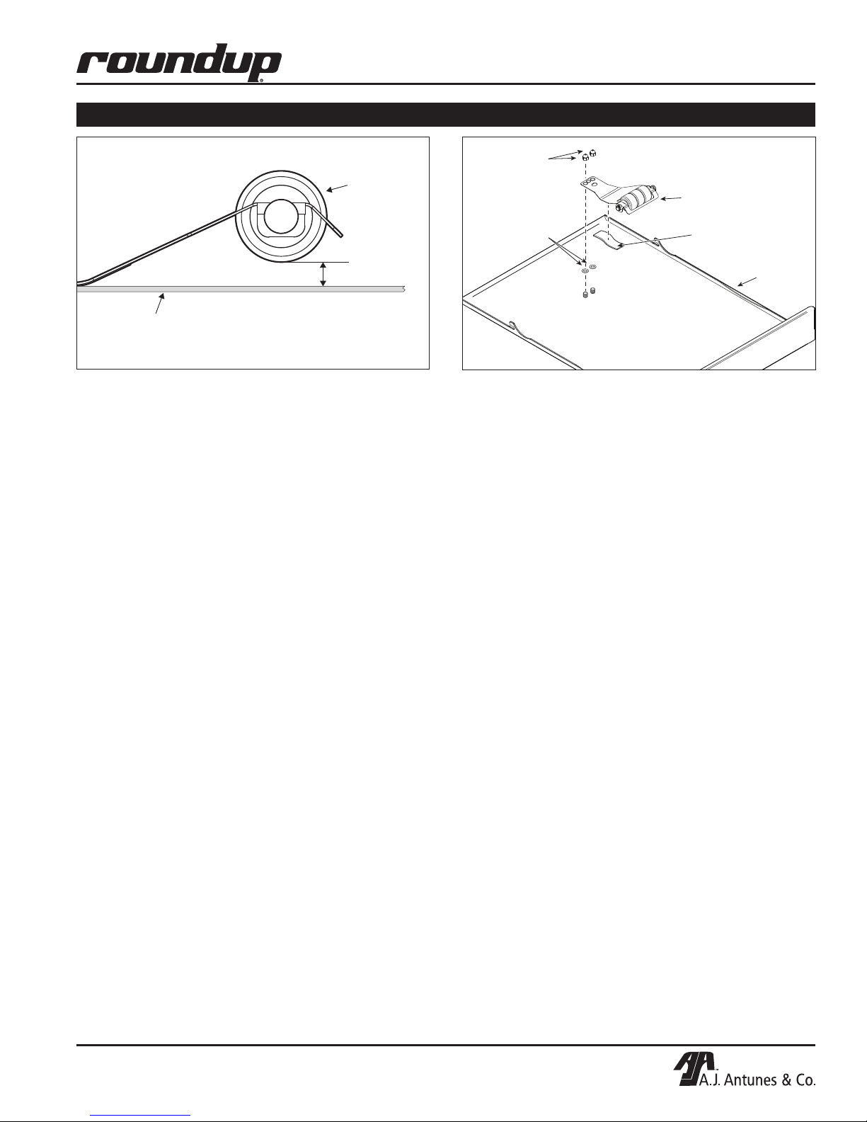
Roller
Tensioner
Assy.
1/2 Inch
Inner Surface
of Conveyor cover
Figure 14. Measuring Roller Tensioner
REPLACING THE CONVEYOR BELT CHAINS
1. Turn the unit off, unplug the power cord, and allow
the unit to cool.
2. Remove the Bun Chute and Heat Shield (Figure
1). Set the Bun Thickness Compression Knobs to
6 and 6.
3. Remove the Conveyor Cover(s) and pull the
Silicone Belt Pin out of the zipper (Figure 9).
4. Remove the Silicone Belt(s).
5. Locate the two Master Links on the Conveyor
Belt Chain and remove both the left and the right
Master Link.
6. Remove the existing Conveyor Belt Chain(s).
7. Place the new Conveyor Belt Chain(s) on the top
sprockets with the hook ends down.
NOTE: The ends of the hooks must point down
(Figure 13).
8. Install the Conveyor Belt Chain around the top
and lower sprockets and connect by replacing
both the left and the right Master Links.
9. Reinstall the Silicone Belt(s).
10. Reinstall the Conveyor Cover(s), Bun Chute, and
Heat Shield.
11. Set the Bun Thickness Compression Knobs to 3
and 4.
12. Return the unit to service.
Acorn Nuts
Roller
Tensioner
Assy.
Spacers
NOTE: Installation is the
same for both the Front
and Rear Conveyor Covers
Tape
Rear
Conveyor
Cover
Figure 15. Measuring Roller Tensioner
Checking the Roller Tensioners
(every 3–6 months)
MEASURING THE ROLLER TENSIONERS
1. Turn the power off, unplug the power cord, and
allow the unit to cool.
2. Remove the Heat Shield.
3. Remove the front and rear Conveyor Covers.
4. Measure the Roller Tensioner on both inner
Conveyor Covers (Figure 14).
5. The space between the inner Conveyor Cover
and bottom of the Tensioner wheel should be no
larger than 1/2”.
6. Adjust or replace the Tensioners as needed.
7. Reinstall the front and rear Conveyor Covers.
8. Reinstall the Heat Shield.
9. Plug in the power cord and test the unit before
returning it to service.
REPLACING/ADJUSTING THE ROLLER TENSIONERS
1. Remove the acorn nuts and old Roller Tensioner
Assembly.
2. Install the new Tensioner Assembly according to
Figure 15.
3. Make sure the spacers are placed inside the
Tensioner arm. The spacers allow the Tensioner
to pivot freely.
4. Make sure there is 1/2” between the bottom of the
Tensioner wheel and the inside of the Conveyor
Cover.
P/N 1011233 Rev. B 09/13
15
Page 16
VERTICAL CONTACT TOASTER
TROUBLESHOOTING
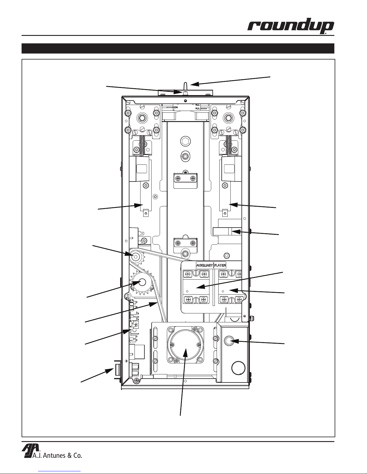
Conveyor Safety
Interlock Switch
Front Auxiliary
Air Heater
Idler
Sprocket
Platen
Rear Auxiliary
Air Heater
Transformer
Drive
Sprocket
Drive
Chain
Control
Board
Power
Switch
Auxiliary
Relay
Platen
Relay
Hi-Limit
Control
Motor
16
P/N 1011233 Rev. B 09/13
Page 17
VERTICAL CONTACT TOASTER
TROUBLESHOOTING (continued)
WARNING
To avoid possible personal injury and/or damage to the unit, inspections, tests and repairs of electrical
equipment should be performed by qualified service personnel. The unit should be unplugged when
servicing, except when electrical tests are required. Use extreme care during electrical circuit tests. Live
circuits will be exposed.
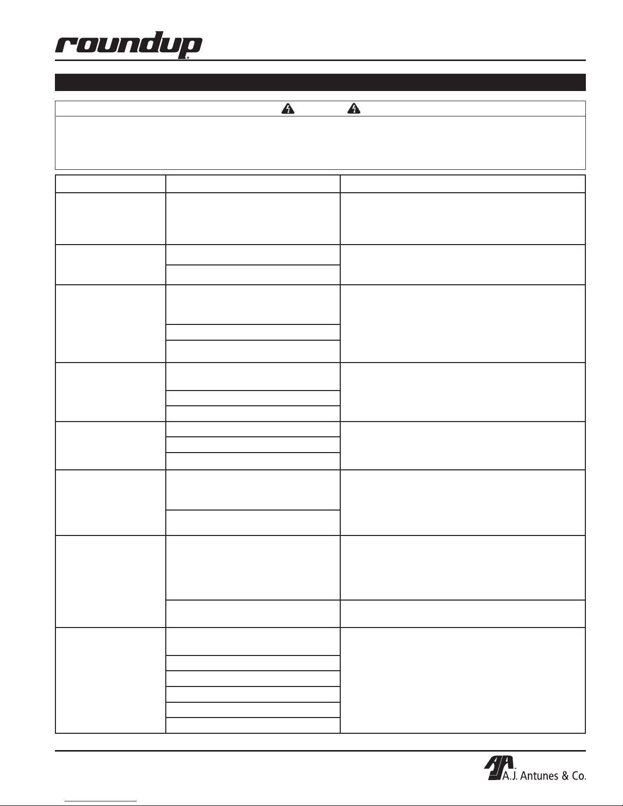
Problem Possible Cause Corrective Action
Control Display flashes
“LO” continuously.
Buns not toasting
properly.
Control Display flashes
“LO” continuously.
Buns burn.
Control Display flashes
“PO” continuously.
Control Display flashes
“CHEC” continuously.
Control Display flashes
“HI” continuously.
Buns burn.
Platen temperature is below 440ºF
(226ºC).
Failed Platen Thermocouple. Contact your maintenance person or Authorized
Failed Control Board.
The power to the unit is below 190
volts.
Failed Control Board.
Failed Transformer.
Control Compartment ambient
temperature is above 140ºF (60ºC).
Failed Cooling Fan.
Failed Control Board.
Failed Platen Solid State Relay. Contact your maintenance person or Authorized
Failed Control Board.
Failed Platen Thermocouple.
Allow the unit to warm up for 30 minutes and then
recheck. If the Control Display still reads “LO”, contact
your maintenance person or Authorized Service
Agency for service.
Service Agency for service.
Turn the power off and then on. If the display still
shows “PO”, check the power cord, plug, and outlet
for damage.
Reset the Circuit Breakers.
Contact your maintenance person, Authorized
Service Agency, or electrician for service.
Verify side vents on toaster are unblocked and not
near other heating appliances. If problem still persists,
contact your maintenance person or
Authorized Service Agency for service.
Service Agency for service.
Control Display flashes
“ERR 9” continuously.
Buns not toasting
properly.
Control Display flashes
“HI” and “USE” after
20–30 minutes.
Control Display
flashes “StoP”.
P/N 1011233 Rev. B 09/13
Loose Platen Thermocouple connection on Control Board or the Platen
Thermocouple is open.
Failed Control Board.
Loose Auxiliary Thermocouple connection on Control Board or Auxiliary
Thermocouple is open.
Faulty Auxiliary Solid State Relay. Contact your maintenance person or Authorized
Mechanical bind in one or both
conveyors.
Defective ball bearings.
Conveyor chains loose or damaged.
Drive chain or sprockets damaged.
Defective motor.
Defective control board.
Re-secure the Platen Thermocouple connection to
the Control Board. If the Control Display still reads
“ERR 9”, check the Thermocouple for continuity.
Contact your maintenance person or Authorized
Service Agency for service.
Re-secure the Auxiliary Thermocouple connection to
the Control Board. If the Control Display still reads
“HI” and “USE”, check Thermocouple for continuity.
Contact your maintenance person or Authorized
Service Agency for service.
Service Agency for service.
Enter “user mode” to check the motor speed.
Check both conveyors for mechanical binds.
Test the motor.
Replace necessary parts.
Contact your maintenance person or Authorized
Service Agency for service.
17
Page 18
VERTICAL CONTACT TOASTER
TROUBLESHOOTING (continued)
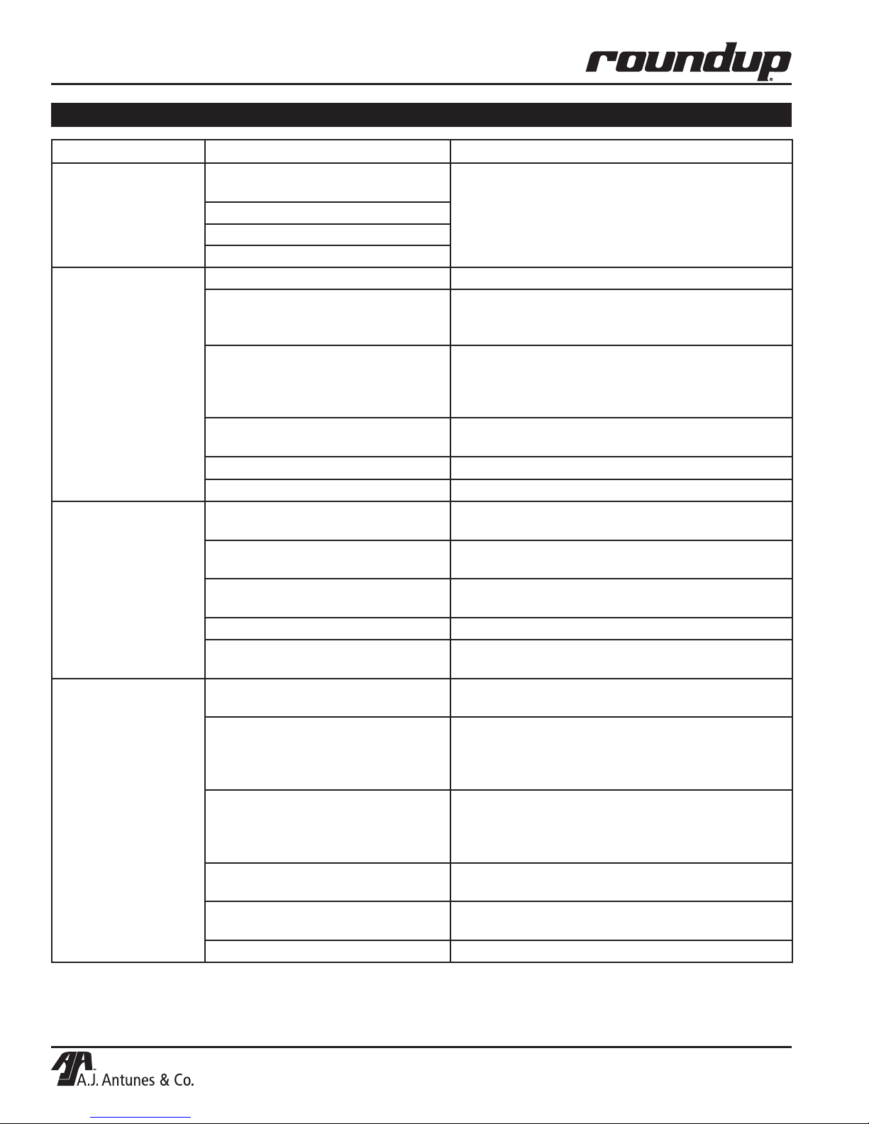
Problem Possible Cause Corrective Action
Control Display
flashes “SpEd”.
No Control Display. Power cord not plugged in. Plug power cord into the proper electrical outlet.
Conveyor does not
turn.
Buns not toasting
adequately.
Mechanical bind in one or both
conveyors.
Damaged ball bearings.
Conveyor chains loose or damaged.
Drive chain or sprockets damaged.
Hi-Limit Control has tripped. Allow unit to cool and reset the Hi-Limit Control. If
Circuit Breakers turned off or tripped.
Damaged electrical outlet, plug, or
cord. Power Switch damaged.
Safety Interlock Switch is not
activated.
Heat Shield is bent or damaged. Replace Heat Shield (P/N 0012541).
Faulty Transformer. Replace Transformer.
Damaged or Missing Roller
Tensioner(s).
Conveyor Belt/Chain has stretched.
Chain skipping on sprockets.
Motor Drive Chain came off
Sprocket(s).
Drive Chain needs lubrication. Lubricate chain with Lubit-8 (P/N 2140152).
Drive Motor has failed. Contact your maintenance person or Authorized
Compression Settings are incorrect. Use the recommended settings. Set Heel to 3 and
Temperature Setting is incorrect. Verify that the Platen (SP-P) is set to 570°F (299°C)
Release Sheet is worn or needs
cleaning (replace every 3–5 weeks).
Silicone Belts are worn or need
cleaning (replace every 2–4 months).
Silicone Belts are not tacky/sticky. Replace or clean Silicone Belts as described in the
Buns do not meet specifications. Contact your bun supplier.
Enter User Mode to check motor speed.
Check both conveyors for mechanical binds.
Replace necessary parts.
Contact your maintenance person or Authorized
Service Agency for service.
it trips again, contact your maintenance person or
Authorized Service Agency.
Reset Circuit Breakers. If they trip again, check the
power cord, plug, and outlet for damage.
Contact your maintenance person, Authorized
Service Agency, or electrician for service.
Reposition the Heat Shield properly.
Adjust or replace Roller Tensioner(s).
Measure and adjust the Conveyor Belt Chains as
described in the Maintenance section of this manual.
Reinstall Drive Chain.
Service Agency for service.
Crown to 4.
and the Auxiliary (SP-A) is set to 330°F (166°C).
For making changes to the setpoint temperature,
see the Installation section of this manual.
Inspect Release Sheet for cleanliness, worn sports,
tears, or wrinkles. Clean or replace Release Sheet
as described in the Maintenance section of this
manual.
Replace or clean Silicone Belts as described in the
Maintenance section of this manual.
Maintenance section of this manual.
18
P/N 1011233 Rev. B 09/13
Page 19
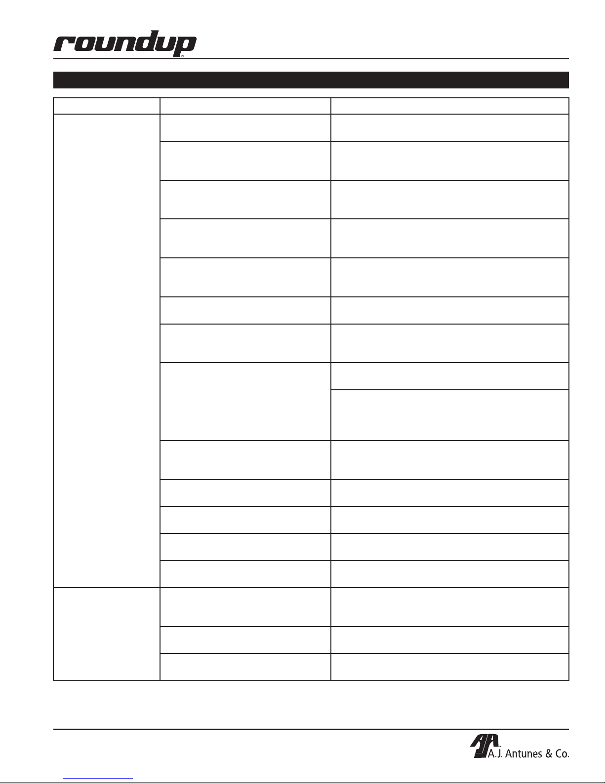
VERTICAL CONTACT TOASTER
TROUBLESHOOTING (continued)
Problem Possible Cause Corrective Action
Crowns and/or Heels
must be forced into
the toaster. Buns
sticking and burning.
New Conveyor
Silicone Belts do not
fit.
Silicone Belts not being cleaned
properly.
Silicone Belts are not tacky/sticky
(replace every 2–4 months).
Silicone Belts are dirty, worn,
or damaged (replace every 2–4
months).
Release Sheet is not being cleaned
properly.
Release Sheet is not being reversed
as required.
Release Sheet is dirty, worn, or
damaged (replace every 3–5 weeks).
Conveyor Belt Chains are skipping
on Sprockets.
Conveyor Safety Interlock Switch
is not being activated by the Heat
Shield.
Silicone Belts slipping over
Conveyor Belt Chains.
Roller Tensioner(s) damaged or
missing.
Drive Motor stalls intermittently. Contact your maintenance person or an Authorized
Compression Settings are incorrect. Use the recommended settings. Set Heel to 3 and
Buns are not inserted into the
toaster properly.
Compression Settings are incorrect. Set Bun Thickness Compression Knobs to 6 and
Silicone Belts not installed correctly. Install Silicone Belts between the Support Rods with
Silicone Belts are damaged or are the
wrong type for your unit.
Clean Silicone Belts as described in the
Maintenance section of this manual.
Clean Silicone Belts. If the Silicone Belts are
too worn, replace them as described in the
Maintenance section of this manual.
Clean or replace Silicone Belts as described in the
Maintenance section of this manual.
Clean both sides of the black and silver Release
Sheet as described in the Maintenance section of
this manual.
Reverse the Release Sheet or replace Release
Sheet as described in the Maintenance section of
this manual.
Clean or replace the Release Sheet as described in
the Maintenance section of this manual.
Measure and adjust the Conveyor Belt Chains as
described in the Maintenance section of this
manual.
Heat Shield is positioned incorrectly. Reposition
Heat Shield.
Heat Shield is damaged. Replace if necessary. If
the Conveyor Safety Interlock Switch is damaged,
contact your maintenance person or Authorized
Service Agency for service.
Remove Silicone Belts and clean the Conveyor Belt
Chain links and Silicone Belts as described in the
Maintenance section of this manual.
Reinstall or replace Roller Tensioner(s) as described
in the Maintenance section of this manual.
Service Agency for service.
Crown to 4.
Buns must be inserted with the cut sides facing
each other on the correct Heel or Crown side.
6 when replacing Silicone Belts or when adjusting
Conveyor Belt Chains.
the zipper flap exposed and hanging down.
Replace with OEM P/N 7000898 only.
P/N 1011233 Rev. B 09/13
19
Page 20
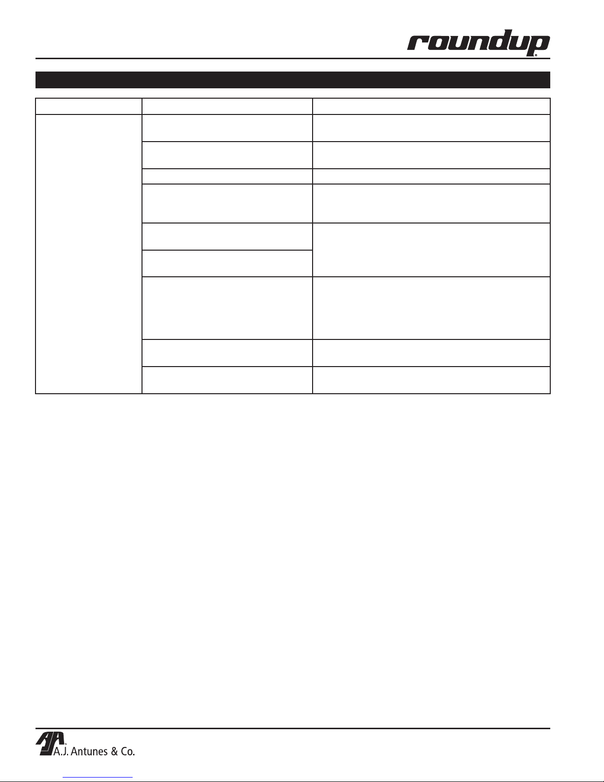
VERTICAL CONTACT TOASTER
TROUBLESHOOTING (continued)
Problem Possible Cause Corrective Action
Toaster makes
unusual sounds.
Compression Settings are too tight. Set Bun Thickness Compression Knobs to the
correct (or larger) setting.
Silicone Belts are installed incorrectly.
Silicone Belt Pin rubbing on housing. Center the Pin in the Silicone Belt zipper.
Roller Tensioner(s) bent or missing. Measure, adjust, or replace the Roller Tensioner(s)
Conveyor Belt Chains have
stretched.
Conveyor Belt Chains adjusted
incorrectly.
Sugar and/or carbon has accumulated inside the Silicone Belt and
between the Conveyor Belt Chain
and Tensioner Slide Rails.
Motor Drive Chain needs lubrication. Lubricate the Drive Chain carefully with Lubit-8 (P/N
A Conveyor Shaft bearing is binding. Contact your maintenance person or Authorized
Silicone Belts must be installed as described in the
Maintenance section of this manual.
as described in the Maintenance section of this
manual.
Measure and adjust the Conveyor Belt Chains as
described in the Maintenance section of this
manual.
Remove Silicone Belts, clean Conveyor Belt Chain
links just as you clean the Silicone Belts daily, and
then clean the Slide Rails on the Tensioners. Next,
clean the Silicone Belt on both sides before
reinstalling it.
2140152) at least once a year.
Service Agency for service.
20
P/N 1011233 Rev. B 09/13
Page 21
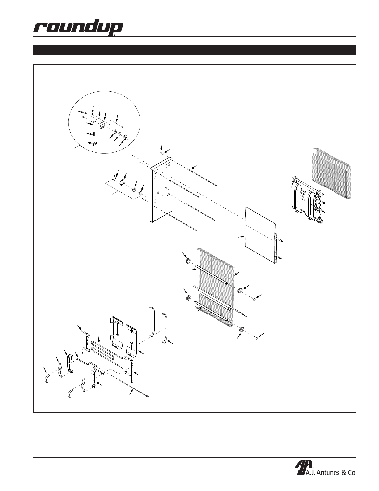
VERTICAL CONTACT TOASTER
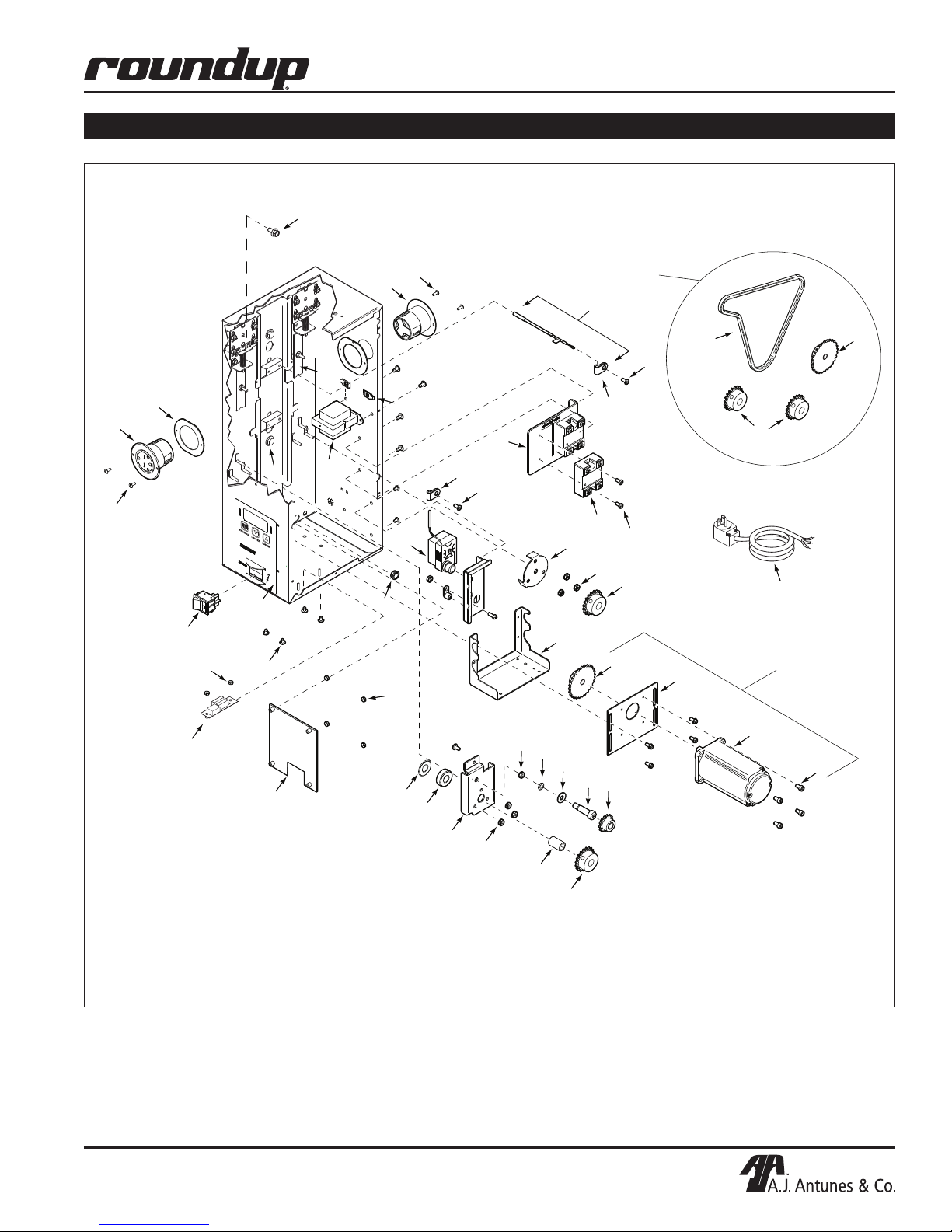
REPLACEMENT PARTS
10
12
13
9
4
5
1
2
3
6
7
8
14
15
10
16
6
7
17
32
33
35
37
38
34
30
39
18
21
26
25
26
27
22
26
24
28/29
24
26
36
40
P/N 1011233 Rev. B 09/13
31
21
Page 22
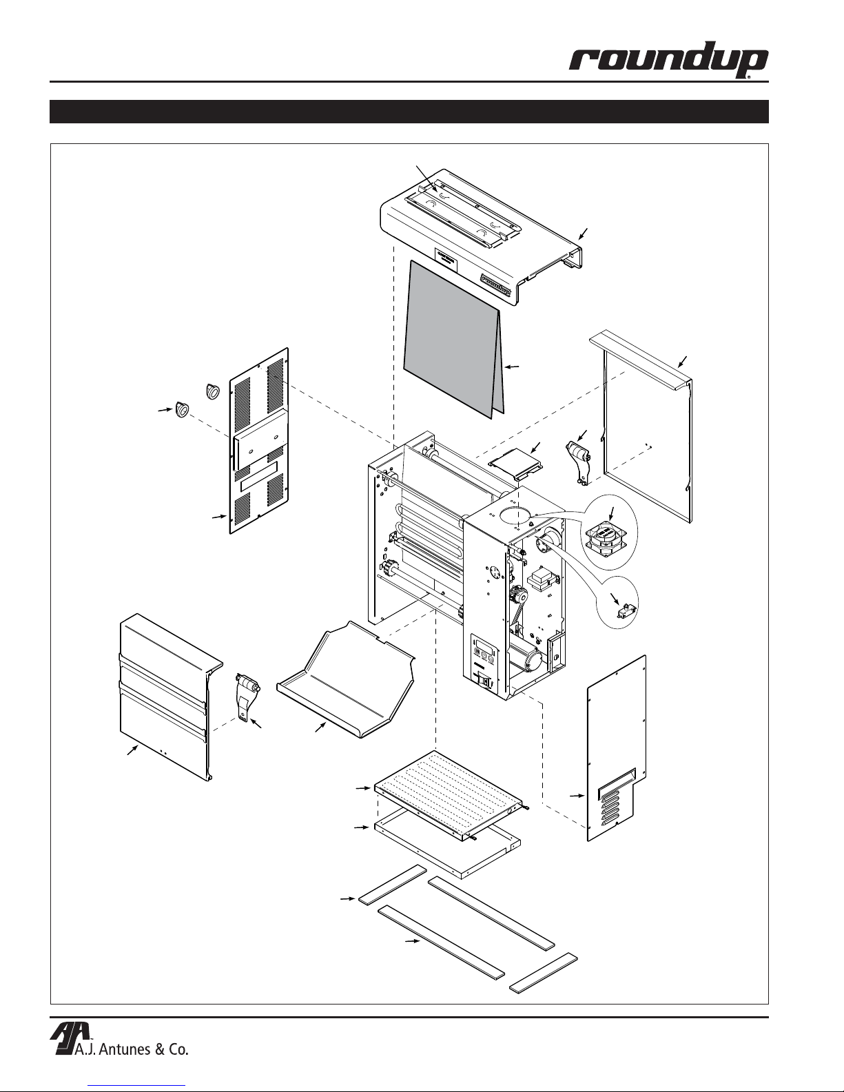
VERTICAL CONTACT TOASTER
REPLACEMENT PARTS (continued)
55
54
53
92
42
96
43
PROGRAM
LIGHTER
DARKER
47
46
48
49
47
95
94
52
50
56
51
22
P/N 1011233 Rev. B 09/13
Page 23
VERTICAL CONTACT TOASTER
REPLACEMENT PARTS (continued)
82
62
60
79
86
61
60
97
62
57
PROGRAM
LIGHTER
DARKER
63
58
85
90
91
84
87
12
83
59
81
58
16
76
77
78
12
87
67
11
10
67
74
73
20
75
74
65
P/N 1011233 Rev. B 09/13
89
88
70
69
64
7
6
66
10
41
68
67
71
72
23
Page 24
VERTICAL CONTACT TOASTER
REPLACEMENT PARTS (continued)
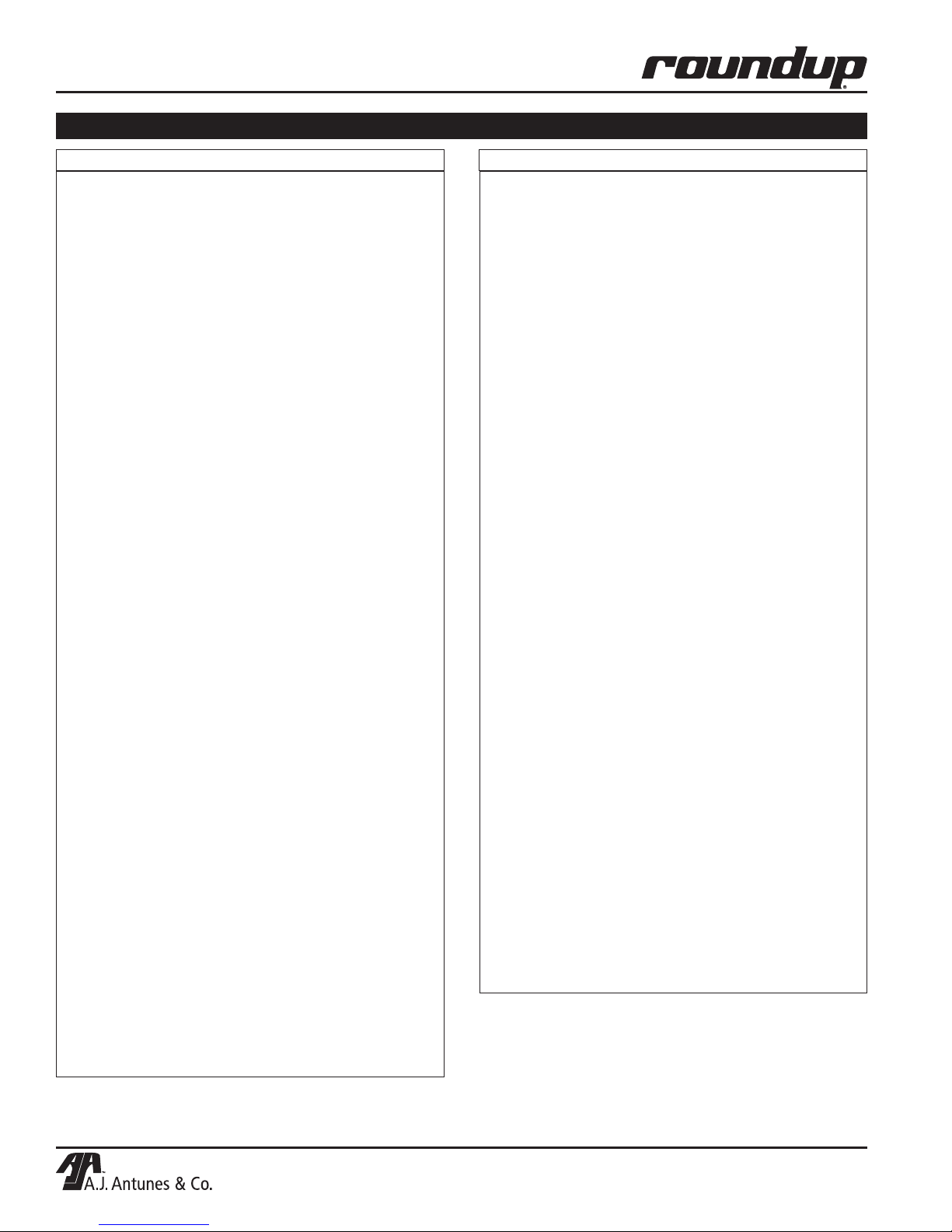
Item Part No. Description Qty.
1 0505987 Spring Guide 4
2 060P153 Compression Spring (Pkg. of 4) 4
3 0505967 Spring Support Bracket 4
4 0506065 Retainer Plate 2
5 308P224* Spacer 3/8" OD x .515” Lg. -
6 7000777 Ball Bearing Kit (Two-Pack) 7 0504320 Spacer, .781" x 1.125" x .06" 2
8 0506066 Bearing Retainer Bracket 4
9 308P223* Washer, Flat #8 -
10 308P143* Nut, Hex KEPS #8-32 Steel -
11 308P115* Mach. Screw #8-32 x 3/8" -
12 308P144* Mach. Screw #8-32 x 1/4" with #6 Head 13 7000778 Idler Bearing Assembly Kit (Incl. #1-12) -
14 306P105* Mach. Screw #6-32 x 1/2" -
15 306P102* Washer, Int. Tooth #06 -
16 0506067 Bearing Retainer 2
17 7000776 Bearing Retainer Kit (Incl. #6, 7, 10 & 16) 1
18 7000774 Support Rod Kit (Incl. #14 & 15) 4
19 7000898 Silicone Belt Kit (not shown) 1
20 0700737 Power Cord (250 Volt, 20 Amp.) 1
(9210318 Only)
0700453 Power Cord (250 Volt, 20 Amp.) 1
(9210319 Only)
21 7000757 Platen (208V/1900W) Kit 22 7000758 Wire Belt Kit -
23 7000770 Master Link Kit (Four-Pack) 24 300P123* Retaining Ring -
25 2150300 Idler Shaft 2
26 7000771 Sprocket, 1/2" Bore Kit (Eight-Pack) -
27 2150299 Drive Shaft 2
28 0021688 Cam Weldment, Front Side 1
29 0021679 Cam Weldment, Back Side 1
30 0021680 Tensioner Assembly 1
31 0503496 Bracket Tensioner Right 2
32 0503497 Bracket Tensioner Left 2
33 4030349 Heating Element (208V/675W) 2
34 0506072 Bracket, Auxiliary Thermocouple 1
35 0504700 Bracket Retainer Left 2
36 0504699 Bracket Retainer Right 2
37 0505968 Tensioner 4
38 7000780 Short Slider Kit (Two-Pack) 39 7000779 Long Slider Kit (Two-Pack) 40 7000775 Thermocouple Type “K”, 1/8" Dia. Kit -
(Incl. #34)
41 2120210 Aluminum Spacer 1
42 2100253 Knob 2
43 0021681 End Housing Panel Weldment 1
46 0012539 Conveyor Cover Front Assy. (Incl. #47) 1
47 7000759 Roller Tensioner Kit (Two-Pack) -
48 0505966 Bun Chute 1
49 0012534 Base Heater Assy. 1
50 0506069 Inner Base 1
51 0200296 Base Gasket 17.25" Lg. 2
52 0012484 Control Housing Cover Assy. 1
Item Part No. Description Qty.
53 0012540 Conveyor Cover Rear Assy. (Incl. #47) 1
54 0012541 Heat Shield Assy. 1
55 7000578 Damper Replacement Kit (Incl.
56 0200293 Base Gasket 8.5" Lg. 2
57 7000882 Rocker Switch Kit 58 304P105* Nut, Hex “KEPS” #4-40 59 4030332 Hi-Limit Thermostat 1
60 4051005 Receptacle (250V/15A) 2
61 0505980 Outer Retainer 2
62 306P103* Mach. Screw #6-32 x 3/8" 63 1001390 Control Label 1
64 7000948 Control Board Replacement Kit -
65 4070154 Varistor Board 1
66 0506064 Idler and Bearing Retainer 1
67 2150181 Sprocket 25B20 1/2" Bore 2
68 0011299 Sprocket/Bearing Assy. 1
69 331P103* Shoulder Bolt 3/8" x 1" 5/16-18 Thrd. 70 212P118* Flat Washer .316" ID x .687" OD x .047" 71 4000199 Gear Motor 1
72 3100199 Screw #10-32 x 3/8 Lg. Socket Head 4
73 0505964 Motor Mounting Plate 1
74 2150295 Sprocket 25B28 .395" Bore 1
75 7000772 Motor Replacement Kit (Incl. #71, 72, 73 & 74)
76 0505956 Motor Mounting Bracket 1
77 7000769 Drive Sprocket and Chain Kit (Incl. #74, 78 & two of 67)
78 2150294 Drive Chain 1
79 7000791 Thermocouple Kit, Type “K” 3/16" Dia. 1
(Incl. #87)
80 4010221 Cap, MP, Motor Run (not shown) 1
81 0400111 Shorty Bushing 1/2" 1
82 3250176 Screw, Flange Hex Head Cap 2
83 4051010 Relay, Solid State 50A Kit 2
84 0503359 Relay Bracket 1
85 308P157* Screw #8-32 x 3/8" -
86 0503150 Heater Clip 2
87 2110197 Metal Cable Clip 2
88 331P106* Lock Washer, 5/16" 89 331P101* Nut, Hex 5/16” x 18 90 4010187 Transformer (240V) 1
91 300P102* Nut, Speed #8-32 “U” 92 7000625 Release Sheet (Pack of 3) 94 7000400 Interlock Switch Kit 95 4000202 Fan, Axial (220/230V) 1
96 0503775 Fan Duct 2
97 7000790 Platen Bolt Kit (4-Pack) 1
* Only available in packages of 10.
Two Sheets and Four Springs)
24
P/N 1011233 Rev. B 09/13
Page 25
VERTICAL CONTACT TOASTER
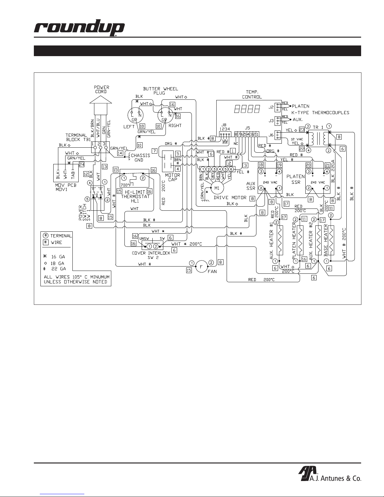
WIRING DIAGRAM
∆
∆
∆
∆
∆
∆
∆
∆
∆
∆
∆
∆ 14 GA
∆
∆
P/N 1011233 Rev. B 09/13
25
Page 26
VERTICAL CONTACT TOASTER
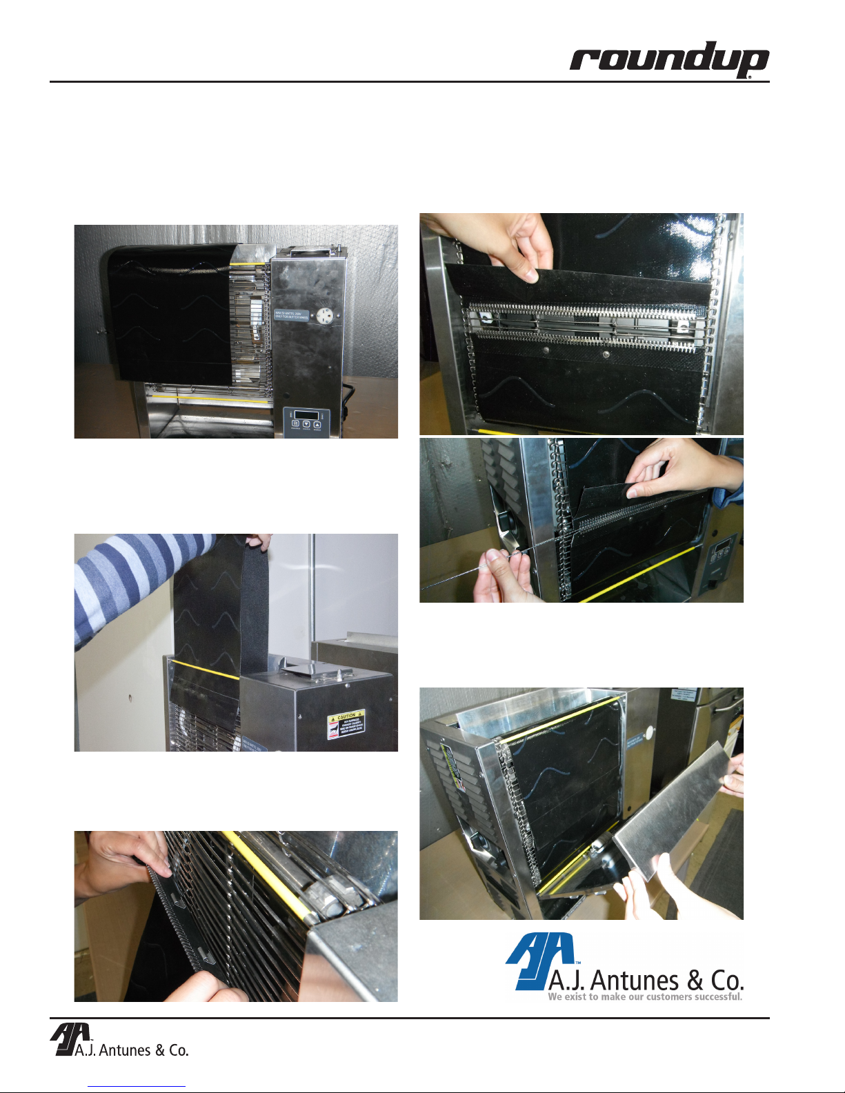
Installing the VCT 2010 Clip Style Belt
VCT-2010 Clip Style Belt Instructions
With power off and toaster cool, set crown and heel
compression knobs to 6 & 6. Remove top cover and both
1
conveyor covers. Remove current belts by either removing lacing
pin or using scissors or razor knife, carefully cut the belt free of
the wire, drive belt.
Pick belt up from the center and feed flap end beneath
2
yellow bar and lower belt until the other end of the belt is
on the bottom of the toaster. Feed belt from the bottom through
bottom yellow bar until both ends are approximately in the
middle of the toaster.
Assure both clips are attached using two wires only to the
4
wire belt. Then position both ends of the new belt together
and line up so the lacing is even. Insert the pin to join both sides
of belt together.
Hook the bottom of each clip to wire belt and gently push
3
the top of the belt upward to clip the top of the clip to the
next metal wire. Make sure clips are fastened to the center
section of the wire belt.
Verify belt alignment is even from side to side of each belt.
5
Set compression knobs to recommended settings of 4 for
the crown and 3 for the heel. Reinstall both conveyor covers and
top cover.
P/N 1011208 7/13
26
P/N 1011233 Rev. B 09/13
Page 27
NOTES
VERTICAL CONTACT TOASTER
P/N 1011233 Rev. B 09/13
27
Page 28

LIMITED WARRANTY
Equipment manufactured by Roundup Food Equipment Division of A.J. Antunes & Co. has been constructed of the finest
materials available and manufactured to high quality standards. These units are warranted to be free from electrical and
mechanical defects for a period of one (1) year from date of purchase under normal use and service, and when installed
in accordance with manufacturer’s recommendations. To insure continued operation of the units, follow the maintenance
procedures outlined in the Owner’s Manual. During the first 12 months, electro-mechanical parts, non-overtime labor, and
travel expenses up to 2 hours (100 miles/160 km), round trip from the nearest Authorized Service Center are covered.
During the first 24 months, coverage for parts only to include the following components: Generator Casting, Solid State
Control, and Motor.
1. This warranty does not cover cost of installation, defects caused by improper storage or handling prior to placing of the
Equipment. This warranty does not cover overtime charges or work done by unauthorized service agencies or personnel.
This warranty does not cover normal maintenance, calibration, or regular adjustments as specified in operating and maintenance instructions of this manual, and/or labor involved in moving adjacent objects to gain access to the equipment.
This warranty does not cover consumable/wear items. This warranty does not cover damage to the Load Cell or Load Cell
Assembly due to abuse, misuse, dropping of unit/shock loads or exceeding maximum weight capacity (4 lbs). This warranty
does not cover water contamination problems such as foreign material in water lines or inside solenoid valves. It does not
cover water pressure problems or failures resulting from improper/incorrect voltage supply. This warranty does not cover
Travel Time & Mileage in excess of 2 hours (100 miles/160 km) round trip from the nearest authorized service agency.
2. Roundup reserves the right to make changes in design or add any improvements on any product. The right is always
reserved to modify equipment because of factors beyond our control and government regulations. Changes to update
equipment do not constitute a warranty charge.
3.
If shipment is damaged in transit, the purchaser should make a claim directly upon the carrier. Careful inspection should be made
of the shipment as soon as it arrives and visible damage should be noted upon the carrier’s receipt. Damage should be reported
to the carrier. This damage is not covered under this warranty.
4. Warranty charges do not include freight or foreign, excise, municipal or other sales or use taxes. All such freight and taxes
are the responsibility of the purchaser.
5. THIS WARRANTY IS EXCLUSIVE AND IS IN LIEU OF ALL OTHER WARRANTIES, EXPRESSED OR IMPLIED, INCLUDING ANY
IMPLIED WARRANTY OR MERCHANTABILITY OR FITNESS FOR A PARTICULAR PURPOSE, EACH OF WHICH IS HEREBY
EXPRESSLY DISCLAIMED. THE REMEDIES DESCRIBED ABOVE ARE EXCLUSIVE AND IN NO EVENT SHALL ROUNDUP BE
LIABLE FOR SPECIAL CONSEQUENTIAL OR INCIDENTAL DAMAGES FOR THE BREACH OR DELAY IN PERFORMANCE OF
THIS WARRANTY.
 Loading...