

Page 1
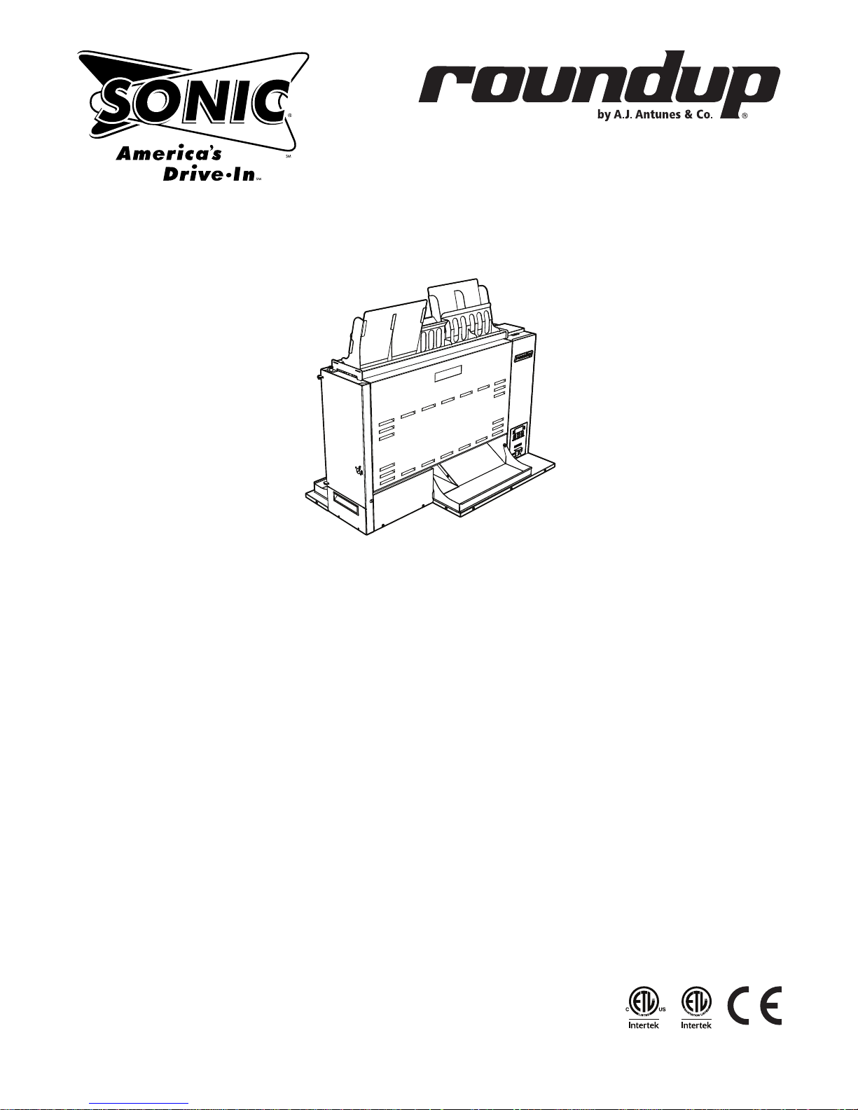
GST-5V
gold standard toaster
Manufacturing Number
9210877
www.ajantunes.com
P/N 1011189 Rev. B 07/14
Page 2
TABLE OF CONTENTS
Warranty Information 2
Service/Technical Assistance 2
Important Safety Information 3
Warnings 3
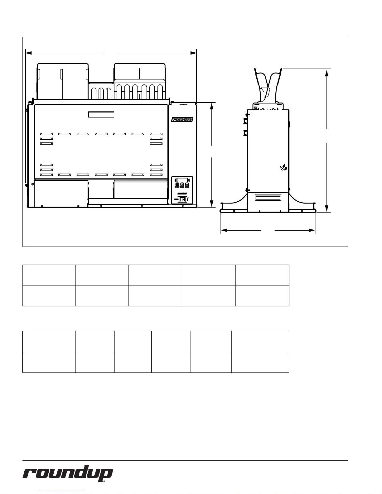
Specications 4
Dimensions – see page 4
Electrical Ratings / Cord & Plug Congurations – see page 4
Installation 5
Operation 5
User Mode 6
Manager Mode 6
Safety Features 6
Hi-Limit Control – see page 6
Purging buns from Toaster – see page 6
Fault Messages 6
Error Codes 6
Daily Cleaning 7
Replacing Belts (Quarterly) 7
Removing Belts – see page 7
Installing Belts – see page 7
Cleaning the Top Cooling Fan and Electrical Housing (Annually) 8
Limited Warranty 10
WARRANTY
INFORMATION
Please read the full text of the Limited
Warranty in this manual.
If the unit arrives damaged, contact
the carrier immediately and le a damage claim with them. Save all packing
materials when ling a claim. Freight
damage claims are the responsibility of
the purchaser and are not covered under
warranty.
The warranty does not extend to:
y Damages caused in shipment or
damage as result of improper use.
y Installation of electrical service.
y Normal maintenance as out-
lined in this manual.
y Malfunction resulting from im-
proper
maintenance.
y Damage caused by abuse or care-
less
handling.
y Damage from moisture into electri-
cal
components.
y Damage from tampering with,
removal of, or changing any
preset control or safety device.
SERVICE/TECHNICAL
ASSISTANCE
If you experience any problems with the
installation or operation of your unit,
contact your local Roundup Authorized
Service Agency.
Fill in the information below and have it
handy when calling your Authorized Service Agency for assistance. The serial number is on the specication plate located on
the rear of the unit.
Purchased From
Date of Purchase
Model Number
Serial Number
Manufacturing Number
IMPORTANT
A.J. Antunes & Co. reserves the
right to change specifications and
product design without notice. Such
revisions do not entitle the buyer to
corresponding changes, improvements, additions or replacements
for previously purchased equip-
ment.
IMPORTANT
Keep these instructions for future refer-
ence. If the unit changes ownership,
be sure this manual accompanies the
equipment.
Use only genuine Roundup replacement
parts in this unit. Use of replacement
parts other than those supplied by the
manufacturer will void the warranty. Your
Authorized Service Agency has been factory trained and has a complete supply of
parts for this unit.
Visit www.ajantunes.com or contact the
factory at 1-630-784-1000 to locate your
nearest Authorized Service Agency.
Refer to the service agency directory
packaged with your manual and ll in the
information below.
Authorized Service Agency
Name
Phone Number
Address
2
P/N 1011189 Rev. B 07/14
Page 3

IMPORTANT SAFETY
INFORMATION
Use the following guidelines for safe operation of the unit.
y Read all instructions be-
fore using equipment.
y For your safety, the equipment is
furnished with a properly grounded
cord connector. Do not attempt to
defeat the grounded connector.
y Install or locate the equipment only
for its intended use as described in
this manual. Do not use corrosive
chemicals in this equipment.
y Do not operate this equipment if
it has a damaged cord or plug, if
it is not working properly, or if it
has been damaged or dropped.
y This equipment should be serviced
by qualied personnel only. Contact
your nearest Authorized Service
Agency for adjustment or repair.
y Do not block or cover any
openings on the unit.
y Do not immerse cord
or plug in water.
y Keep cord away from
heated surfaces.
y Do not allow cord to hang over
edge of table or counter.
y Turn the power o, unplug the
power cord, and allow unit to
cool down before performing any
service or maintenance on the unit.
NOTE: Turning o the power switch
does NOT turn o all power to
the unit.
y The equipment should be grounded
according to local electrical codes to
prevent the possibility of electrical shock. It requires a grounded
receptacle with separate electrical
lines, protected by fuses or circuit
breaker of the proper rating.
y All electrical connections must
be in accordance with local electrical codes and any
other applicable codes.
y Do not clean this appli-
ance with a water jet.
WARNINGS
Be advised of the following warnings
when operating and performing maintenance on this unit.
y If the supply cord is damaged, it
must be replaced by the manufacturer or its service agent or
a similarly qualied person
in order to avoid a hazard.
y Do not modify the power sup-
ply cord plug. if it does not t
the outlet, have a proper outlet
installed by a qualied electrician.
y Do not use an extension
cord with this appliance.
y Electrical ground is re-
quired on this appliance.
y Check with a qualied electrician if
you are in doubt as to whether the
appliance is properly grounded.
y If a chemical cleaner is used, be
sure it is safe to use on cast aluminum. Observe all precautions
and warnings on product label.
y Inspection, testing, and repair
of electrical equipment should
only be performed by qualied service personnel.
y Do not use a sanitizing solu-
tion or abrasive materials. The
use of these may cause damage
to the stainless steel nish.
y Chlorides or phosphates in clean-
ing agents (e.g. bleach, sanitizers,
degreasers or detergents) could
cause permanent damage to
stainless steel equipment. The
damage is usually in the form of
discoloration, dulling of metal
surface nish, pits, voids, holes, or
cracks. This damage is permanent
and not covered by warranty.
y The following tips are recom-
mended for maintenance of your
stainless steel equipment:
• Always use soft, damp cloth for
cleaning, rinse with clear water
and wipe dry. When required,
always rub in direction of metal
polish lines.
• Routine cleaning should be done
daily with soap, ammonia detergent, and water.
• Stains and spots should be
sponged using a vinegar solution.
• Finger marks and smears should
be rubbed o using soap and
water.
• Hard water spots should be removed using a vinegar solution.
P/N 1011189 Rev. B 07/14
3
Page 4
SPECIFICATIONS
A
D
C
Dimensions
Model &
Mfg. No.
GST-5V
9210877
Width
(A)
35" (889 mm) 20" (508 mm)
Depth
(B)
Electrical Ratings / Cord & Plug Congurations
Model &
Mfg. No.
GST-5V
9210877
Volts Watts Amps Hz Plug Description
208-240 5000-5760 24 50/60
Height
(C)
21 1/2" (546 mm)
(without Bun Feeder
B
Height
(D)
29 1/2” (749 mm)
(with Bun Feeder)
Twist Lock
L6-30 P
4
P/N 1011189 Rev. B 07/14
Page 5
INSTALLATION
1. Remove unit and all packing mate-
rials from shipping carton.
2. Open the Accessories Box. It should
contain the following:
• Bun Chute
• Bun Feeder
• 1 Belt Set
• Owner’s Manual
NOTE: If any parts are missing or dam-
aged, contact Antunes Technical Service IMMEDIATELY at
1-877-392-7854 or 1-630-784-
1000.
3. Remove all packing materials and
protective coverings from the unit.
4. Wipe the entire exterior of the
toaster and the accessories mentioned above with a hot damp
cloth. Allow to air dry
NOTE: Do NOT use a dripping wet
cloth. Wring out before use.
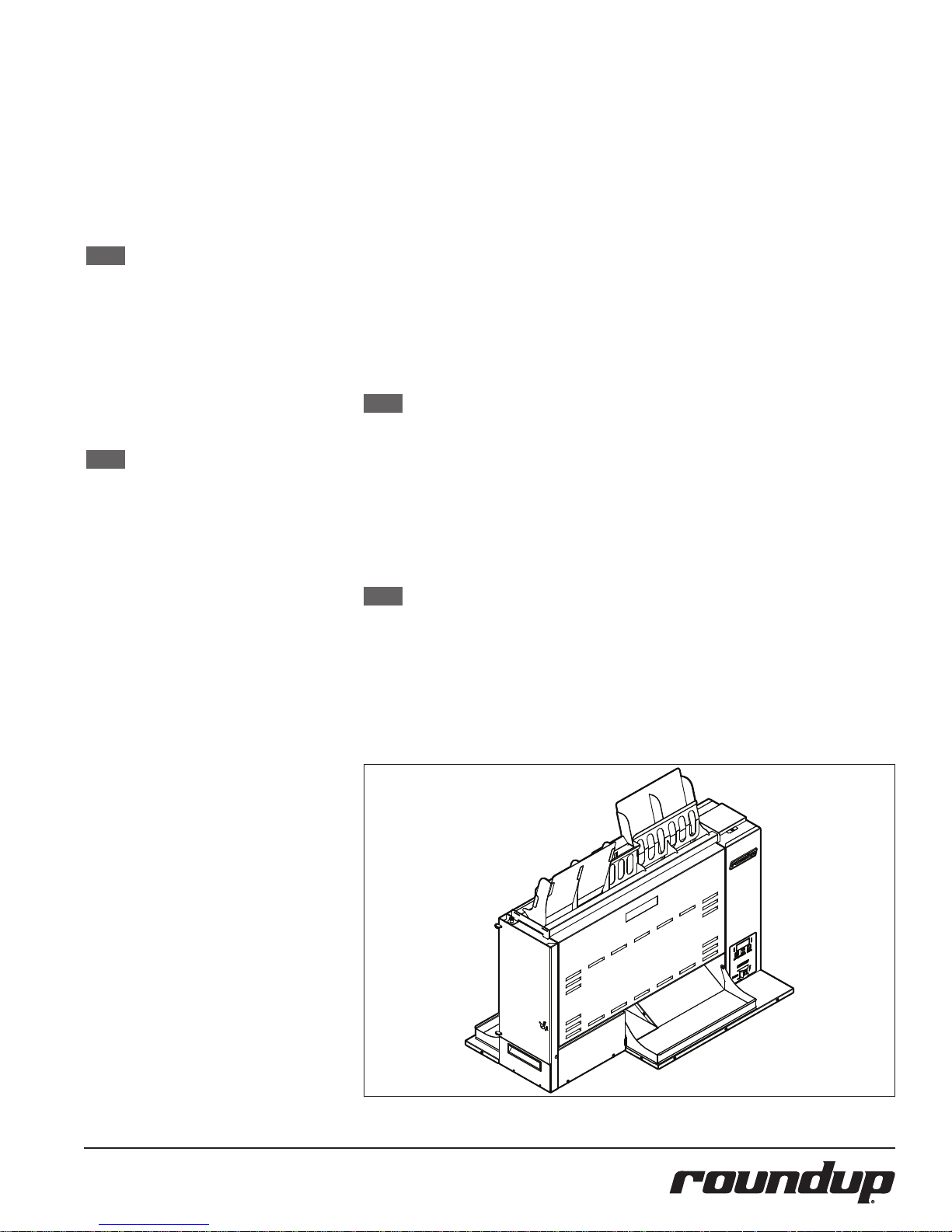
5. Attach the Bun Chute and Bun
Feeder.
When placing the toaster into service,
pay attention to the following guidelines.
y Make sure the power switch is o
and the unit is at room temperature
before plugging in the power cord.
y Do not block or cover any
openings on the unit.
y Do not immerse the power
cord or plug in water.
y Keep the power cord away
from heated surfaces.
y Do not allow the power cord to
hang over edge of table or counter.
y Place the unit on a sturdy, level
table or other work surface..
y Turn the power switch to
o (if it is set to on).
y Ensure the line voltage cor-
responds to the stated voltage
on the specication label and
power cord warning tag.
y Plug the power cord into the
appropriate power outlet. Refer to the specication plate
for the proper voltage.
OPERATION
1. Turn the unit on and allow it to
warm up until USE appears in the
display
2. Drop product into the appropriate
lane on the Bun Feeder according
to Bun Feeder labels. Insert buns
with the cut side facing away from
the front of the toaster
3. Finished product drops into the bun
landing zone.
LIGHT/DARK ADJUSTMENTS
The light/dark value can be adjusted when
the unit is displaying “USE”. To adjust the
light/dark value, press the LIGHTER or
DARKER button. The display will change to
show the current light/dark value.
NOTE: The default light/dark value is
d0.
Press the LIGHTER or DARKER buttons to
change the light/dark value. The adjustment range is L1-L9 and d0-d9. L9 is the
lightest, d0 is the middle, and d9 is the
darkest setting.
To save the light/dark value, press the PRO-
GRAM button or wait 5 seconds until the
screen displays “USE”.
NOTE: Adjusting the light/dark value
does NOT change the temperature. It changes the speed of the
conveyors. The light/dark value
will reset to the d0 value when
the unit is turned o.
P/N 1011189 Rev. B 07/14
Figure 1.
5
Page 6
USER MODE
User Mode allows an operator to view the
toaster settings but does not permit any
adjustments.
1. Press and hold the PROGRAM but-
ton for 5 seconds. After 5 seconds,
the display will show the actual
temperature of the Rear Platen.
2. Press the LIGHTER button to toggle
between the setpoint and actual
temperature of the Rear Platen
Heater.
3. Press the PROGRAM button to
proceed to the Front Platen Heater
menu. The display shows the actual
temperature of the Front Platen.
4. Press the LIGHTER button to toggle
between the setpoint and actual
temperature of the Front Platen.
5. Press the PROGRAM button to
proceed to the Motor Menu. The
display shows the actual speed of
the motor.
6. Press the LIGHTER button to toggle
between the setpoint and actual
speed of the Motor.
NOTE: The unit will exit User Mode af-
ter 5 seconds of keypad inactivity.
MANAGER MODE
Manager Mode allows an operator to view
and adjust the following settings:
• Rear Platen Temperature
• Front Platen Temperature
• Motor Speed
• Temperature Units (Celsius or
Fahrenheit)
• Current Selection: 208 or 240 volts
Manager Mode also allows an operator to
view (but not adjust) the Ambient Temperature of the Control Compartment as
well as the number of days of operation.
1. Turn the unit o.
2. Turn the power on while holding
the PROGRAM button.
3. Release the PROGRAM button. The
display shows the Platen Setpoint
Temperature.
4. Enter the appropriate code and
press the PROGRAM button.
5. To adjust the Platen Setpoint
Temperature, press the LIGHTER
or DARKER buttons to reach the
desired temperature.
NOTE: The recommended temperature
setting for the Rear Platen is 545
F (285 C).
6. Press the PROGRAM button to pro-
ceed to the Front Heater Setpoint
Temperature.
7. To adjust the Front Heater Setpoint
Temperature, press the LIGHTER
or DARKER buttons to reach the
desired temperature.
NOTE: The recommended temperature
setting for the Front Platen is
545° F (285° C)
8. Press the PROGRAM button to
procedure to the Motor Speed
Setpoint.
9. Adjust the Motor Speed Setpoint by
pressing the LIGHTER or DARKER
buttons to reach the desired speed.
NOTE: the Motor Speed is adjustable
from 1-100. The recommended
setting is 51.
10. Press the PROGRAM button to pro-
ceed to the Temperature Units.
11. To change the Temperatures units
from Fahrenheit or Celsius, press
the LIGHTER or DARKER buttons.
12. Press the PROGRAM button to pro-
ceed to the Ambient Temperature
of the Control Compartment.
NOTE: No changes can be made to the
Ambient Temperature of the
Control Compartment. Temperatures under 150° F (66° C) are
acceptable.
13. Press and hold the PROGRAM but-
ton to save any changes.
NOTE: The unit exits Manager Mode
after 30 seconds of keypad inactivity.
SAFETY FEATURES
Hi-Limit Control
A Hi-Limit Control turns o electrical power
to the heaters and control circuits if the
unit overheats. To reset the control:
1. Let the unit cool for 10 - 15 minutes.
2. Locate the two Hi-Limit Controls on
the rear of the unit. Remove the two
black protective cap.
3. Press and release both buttons.
Reinstall the protective caps.
NOTE: If the Hi-Limit Controls require
continuous resetting, contact
your Authorized Service Agency.
Purging buns from Toaster
If buns get stuck in the toaster, press and
hold both the UP and DOWN arrow buttons to increase the belt speed until the
buns are purged from the toaster.
FAULT MESSAGES
The unit displays fault messages when
there is a problem with the unit.
“Hi” ashes if the Rear Platen Heater temperature is 30° F more than the setpoint or
if the Rear Platen Thermocouple is disconnected or open.
“CHEC” ashes when the control compartment ambient temperature is more than
150° F (66° C). All heaters shut o. The unit
will not restart until the control compartment ambient temperature falls below
140° F (60° C).
“PO” ashes if the incoming power drops
below 190 volts. The toaster shuts down.
“StoP” ashes when the motor has stopped
for seven continuous seconds.
“SpEd” ashes when the motor speed
drops 25% below the Setpoint for 30 continuous seconds.
ERROR CODES
If any of the following Error Codes appear,
turn the power o, allow the unit to cool,
and turn the power back on. If the error
repeats, contact your Authorized Service
Agency for assistance.
Error Description
ERR 1 Internal Error. Cycle the Power
Switch. If error persists, replace the
board.
ERR 2 Internal Error. Cycle the power
Switch. If error persists, replace the
board.
ERR 3 Internal Error. Cycle the power
Switch. If error persists, replace the
board.
ERR 4 Invalid DIP Switch setting. The only
approved setting is (left to right)
up-up-up- down (1 on, and 2,3,4
o).
ERR 5 Internal Error. Cycle the power
Switch. If error persists, replace the
board.
ERR 6 Internal Error. Cycle the power
Switch. If error persists, replace the
board.
ERR 7 Not used.
ERR 8 Shorted Platen Thermocouple
ERR 9 Open Platen Thermocouple.
6
P/N 1011189 Rev. B 07/14
Page 7

DAILY CLEANING
1. Turn the toaster’s power switch to
the o position. The toaster enters
a 45 minute cool-down mode and
automatically shuts down when
complete.
NOTE: Be sure to perform cleaning
steps during cool-down mode.
2. Put on neoprene gloves and re-
move the Bun Feeder.
3. Clean the outside surfaces of the
toaster with a paper towel sprayed
with an approved multi-surface
cleaner. Allow to air dry.
4. Wipe the Bun Feeder Assembly with
a paper towel sprayed with an approved multi-surface cleaner. Allow
to air dry.
5. Wash, rinse, and sanitize the Bun
Wheel assembly at the sink and
allow to air dry.
6. Remove the Front and Rear Con-
veyor Covers by lifting up and away
from the unit.
NOTE: Replace all Belts if any of the
Belts are discolored, torn, or if
any of the Belt Snaps are damaged.
NOTE: Only clean the rear Belt when it
is in front of the Backing Plate.
This avoids causing damage to
the Belt. The conveyors continue
to turn during the cool-down
period.
7. Inspect the front and rear Belts. Re-
place all of the belts if any of them
are torn, folded, discolored, missing
snaps, or damaged in any way.
8. If the Belts are all in good condition,
spray a clean, sanitized towel with
an approved sanitizer. Press and
hold both arrow buttons for 5 seconds. PUR appears on the display
with a blinking cursor. This locks
the belt speed in Purge mode for 5
minutes to assist in cleaning. Wipe
the front and rear Belts clean. Allow
to air dry.
9. Press any button to exit Purge
mode.
NOTE: Only clean the Belt where it is in
front of the Backing Plate. This
avoids causing damage to the
Belt.
10. Clean the Front and Rear Conveyor
Covers with a paper towel sprayed
with an approved multisurface
Cleaner. Allow to air dry.
P/N 1011189 Rev. B 07/14
11. Reinstall the Front and Rear Con-
veyor Covers and then re-install the
Bun Feeder.
12. Turn the toaster on and test the unit
before returning it to operation.
NOTE: These cleaning steps may need
to be repeated to remove heavy
carbon buildup.
NOTE: Be sure to clean and sanitize
the Belts completely. Failure
to properly clean the Belts will
shorten the life of the Belts and
result in poor toaster performance.
NOTE: Replace all Belts if any of the
Belts are discolored, torn, or
if any of the Belt Snaps are
damaged. To obtain new Belts,
contact the factory at 1-877392-7854 (North America only)
or 630-784-1000.
NOTE: Belts should be removed ONLY
during Belt replacement or
when required in a service situation.
REPLACING BELTS
QUARTERLY
Over time, the Belts begin to show signs of
wear. This wear appears in the form of tears
or discoloration of the belt, at which point
all belts should be replaced.
NOTE: Belts should be removed ONLY
during Belt Replacement or
when required in a service
situation. For proper operation,
replace all belts at the same
time.
Removing Belts
1. Turn the toaster o’s power switch
to the o position. The toaster
enters a cool-down mode and will
automatically shut down when
complete.
2. Unplug the power cord once the
cool-down period is complete.
3. Put on neoprene gloves. Remove
the Bun Feeder.
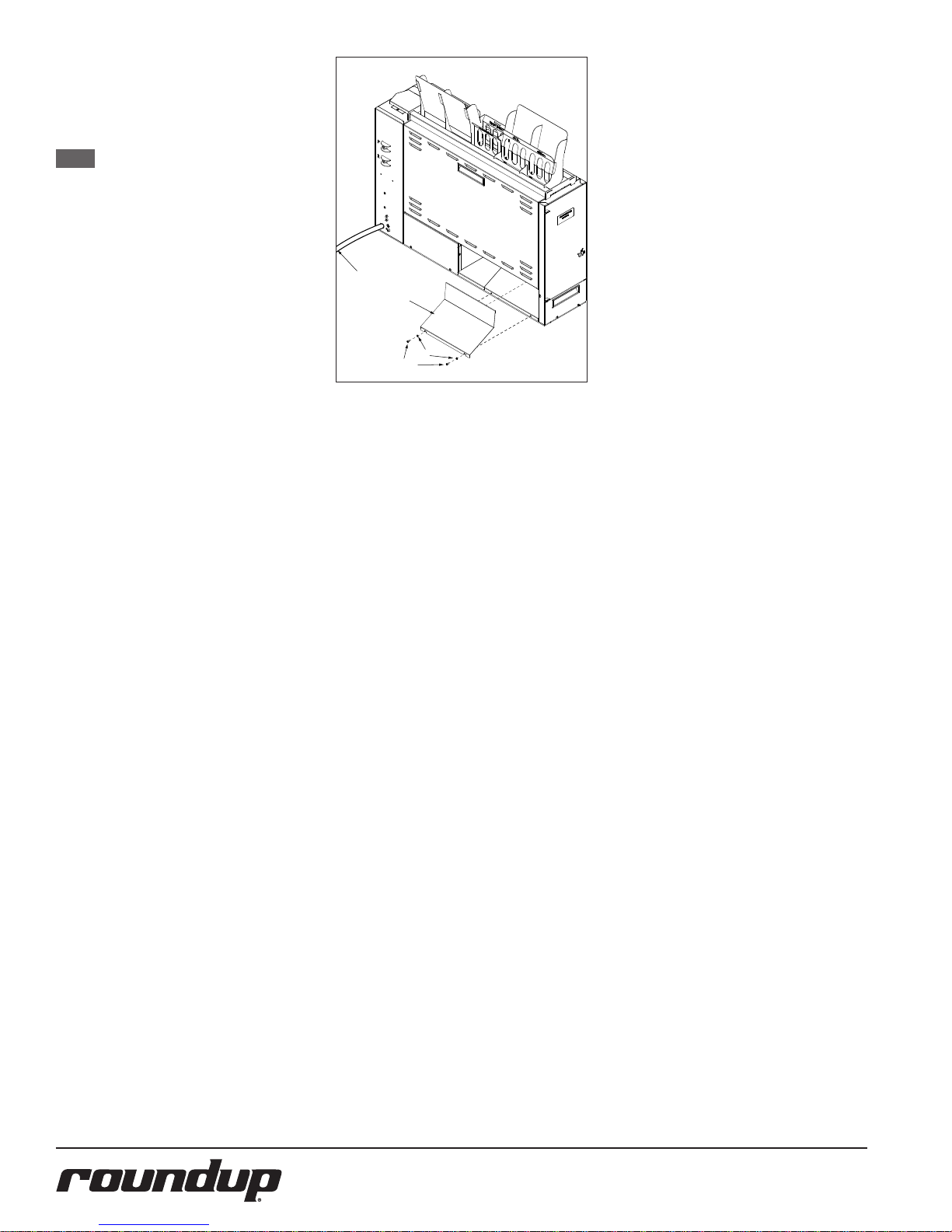
4. Remove the Bun Ramp as shown in
Figure 2, next page)
5. Remove the Front and Rear Con-
veyor Covers by lifting up and away
from the toaster.
6. Set the Compression Knob to 7.
7. Unlock the latch and open the left
side panel.
7
8. To lock out the front Conveyor
Roller, face the front of the toaster.
Use both hands and push down on
the Front Conveyor Roller and pull
towards you. This removes tension
and locks the roller in place (Figure
zx).
9. To lock out the Rear Roller, face the
rear of the toaster. Use both hands
and push down on the Rear Conveyor Roller and push away from
you. This removes tension and locks
the roller in place (Figure zx)
10. Lift the upper Belt Frame Lock. Then
rotate down so it rests on the cam
shaft of the rear conveyor roller.
11. Pull down the lower Belt Frame
Lock.
12. Using a utility knife, cut the existing
Front Belts and remove from the
toaster. Discard the old Belts.
13. Using a utility knife, cut the Rear
Belt and remove from the toaster.
Discard the old Belt.
Installing Belts
NOTE: To obtain new Belts, contact the
factory at 1-877-392-7854
(North America only) or 630784-1000.
1. Follow the steps for Removing Belts.
2. Wipe both sides of the new Belts
with a clean, sanitized towel
sprayed with an approved sanitizer
and allow to air dry.
3. Slide the new rear belt gently over
the rear top roller and rear bottom
roller.
NOTE: Make sure the belt lines up
properly on the rollers. The
snaps on the belts should face
the inside of the top front roller.
4. Slide the Heel/Texas Toaster belt
over the front bottom roller. Repeat
this step for the crown belt.
NOTE: Make sure the belt lines up
properly on the rollers. The
snaps on the belts should face
the inside of the top rear roller.
Belts must be installed so the
exposed diagonal seam of the
belt is away from the direction
of belt travel.
5. Return the Front and Rear Belt Roll-
ers to full tension by sliding them
toward each other so each roller
locks into place.
6. Slowly lift up the Lower Belt Frame
Lock so the Front and Rear Belt Rollers lock into place.
Page 8
7. Re-engage the Upper Belt Frame
Lock by lifting up and then locking
it in place on the Front Conveyor
Assembly.
8. Close and latch the Side Panel.
NOTE: Inform the Store Manager after
any Belt Replacement so new
Belts can be ordered. To obtain
new Belts, contact the factory at
1-877-392-7854 (North America
only) or 630-784-1000.
9. Set the Compression Knob to 4.
10. Re-install the Front and Rear
Conveyor Covers and then the Bun
Feeder Assembly.
11. Reinstall the Bun Ramp (Figure 2).
12. Plug in the toaster and test the unit
before returning to service.
CLEANING THE TOP
COOLING FAN AND ELEC
TRICAL HOUSING ANNU
ALLY
Power Cord
(Rear of Unit)
Bun Ramp (1)
Spacer (2)
Screw (2)
Figure 2. Bun Ramp
Follow these steps to clean the top fan.
1. Turn the power switch to the OFF
position. The toaster enters a cooldown mode and will automatically
shut down when complete.
2. Unplug the power cord.
3. Facing the front of the toaster,
move to the right Side Panel.
Remove the right Side Panel and set
aside. Do not lose the screws.
4. Remove the Fan Duct cover from
the top of the unit and set aside. Do
not lose the screws.
5. Use a plastic brush or similar tool to
brush all 5 fan blades from above
and below. Be sure to remove all
debris.
6. Carefully clean any debris from the
inside oor of the control compartment and from all electrical connections. Be sure to remove any grease,
lint, or debris from these areas.
7. Reattach the right Side Panel
and Fan Duct cover securely with
screws.
8
P/N 1011189 Rev. B 07/14
Page 9

THIS PAGE LEFT INTENTIONALLY BLANK
P/N 1011189 Rev. B 07/14
9
Page 10
LIMITED WARRANTY
Equipment manufactured by Roundup Food Equipment Division of A.J. Antunes & Co. has been constructed of the finest
materials available and manufactured to high quality standards. These units are warranted to be free from electrical and
mechanical defects for a period of one (1) year from date of purchase under normal use and service, and when installed in
accordance with manufacturer’s recommendations. To insure continued operation of the units, follow the maintenance procedures outlined in the Owner’s Manual. During the first 12 months, electro-mechanical parts, non-overtime labor, and travel
expenses up to 2 hours (100 miles/160 km), round trip from the nearest Authorized Service Center are covered.
1. This warranty does not cover cost of installation, defects caused by improper storage or handling prior to placing of the
Equipment. This warranty does not cover overtime charges or work done by unauthorized service agencies or personnel. This
warranty does not cover normal maintenance, calibration, or regular adjustments as specified in operating and maintenance
instructions of this manual, and/or labor involved in moving adjacent objects to gain access to the equipment. This warranty
does not cover consumable/wear items. This warranty does not cover damage to the Load Cell or Load Cell Assembly due
to abuse, misuse, dropping of unit/shock loads or exceeding maximum weight capacity (4 lbs). This warranty does not cover
water contamination problems such as foreign material in water lines or inside solenoid valves. It does not cover water
pressure problems or failures resulting from improper/incorrect voltage supply. This warranty does not cover Travel Time &
Mileage in excess of 2 hours (100 miles/160 km) round trip from the nearest authorized service agency.
2. Roundup reserves the right to make changes in design or add any improvements on any product. The right is always reserved
to modify equipment because of factors beyond our control and government regulations. Changes to update equipment do
not constitute a warranty charge.
3.
If shipment is damaged in transit, the purchaser should make a claim directly upon the carrier. Careful inspection should be made
of the shipment as soon as it arrives and visible damage should be noted upon the carrier’s receipt. Damage should be reported to
the carrier. This damage is not covered under this warranty.
4. Warranty charges do not include freight or foreign, excise, municipal or other sales or use taxes. All such freight and taxes
are the responsibility of the purchaser.
5. THIS WARRANTY IS EXCLUSIVE AND IS IN LIEU OF ALL OTHER WARRANTIES, EXPRESSED OR IMPLIED, INCLUDING ANY IMPLIED WARRANTY OR MERCHANTABILITY OR FITNESS FOR A PARTICULAR PURPOSE, EACH OF WHICH
IS HEREBY EXPRESSLY DISCLAIMED. THE REMEDIES DESCRIBED ABOVE ARE EXCLUSIVE AND IN NO EVENT
SHALL ROUNDUP BE LIABLE FOR SPECIAL CONSEQUENTIAL OR INCIDENTAL DAMAGES FOR THE BREACH OR
DELAY IN PERFORMANCE OF THIS WARRANTY.
 Loading...