

Page 1
START/STOP
PROGRAM
DOWN
UP
POWER
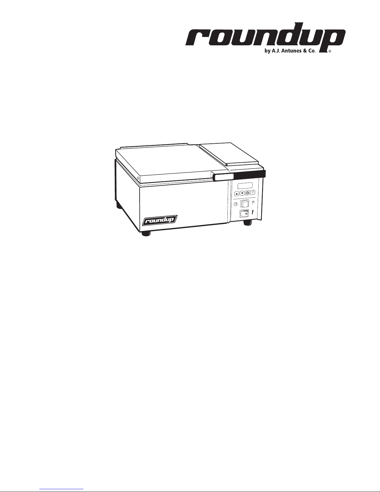
DFW series
deluxe food warmer
owner’s manual
Manufacturing Numbers:
9100101, 9100102, 9100103, 9100104,
9100105, 9100106, 9100107, 9100111,
9100112, 9100113, 9100114, 9100115,
9100116, 9100118, 9100121, 9100122,
9100123, 9100124, 9100125, 9100126,
9100128, 9100131, 9100132, 9100133,
9100134, 9100135, 9100136, 9100146,
9100147, 9100156
www.ajantunes.com
P/N 1010678 Rev. K 08/12
Page 2
Table of Contents
General .................................................. 2
Warranty Information ............................. 2
Service/Technical Assistance ................... 2
Important Safety Information ................. 3
Warnings ................................................ 3
Specifications ......................................... 4
Shipping Weight ..................................... 4
Capacities ............................................... 4
Installation ............................................. 5
Plumbing ................................................ 5
General information ............................... 6
Operating Instructions ............................ 6
Programming ......................................... 7
Hi-Limit Reset Button ............................. 8
Fault Codes ............................................8
Diagnostic LEDs ...................................... 8
Daily Maintenance ................................. 8
Monthly Maintenance ............................ 9
Troubleshooting...................................... 11
Cooking Guide ....................................... 14
Replacement Parts ..................................15
Replacement Parts
– DFW/DFWT-100/150 ...........................16
Replacement Parts
– DFW/DFWT-200/250 ............................ 18
Replacement Parts
– DFWF-250 ONLY ................................ 20
Wiring Diagram ...................................... 22
Limited Warranty .................................... 24
IMPORTANT
A.J. Antunes & Co. reserves the right
to change specifications and product
design without notice. Such revisions do
not entitle the buyer to corresponding
changes, improvements, additions or
replacements for previously purchased
equipment.
IMPORTANT
Keep these instructions for future reference. If the unit changes ownership,
be sure this manual accompanies the
equipment.
GENERAL
The Deluxe Food Warmer (steamer) produces a
steam using plain tap water for quick heating
and reconstituting of food items. Simple pushbutton action delivers a shot of water that is
immediately converted into steam. Because
the amount of steam is consistent, it removes
the guesswork and produces a uniform finish
from one operator to the next.
This manual provides the safety, installation,
and operating procedures for the Deluxe Food
Warmer (steamer). We recommend that all
information contained in this manual be read
prior to installing and operating the unit.
Your Deluxe Food Warmer (steamer) is manufactured from the finest materials available
and is assembled to Roundup’s strict quality
standards. This unit has been tested at the
factory to ensure dependable trouble-free
operation.
WARRANTY INFORMATION
Please read the full text of the Limited
Warranty in this manual.
If the unit arrives damaged, contact the carrier immediately and file a damage claim with
them. Save all packing materials when filing a
claim. Freight damage claims are the responsibility of the purchaser and are not covered
under warranty.
The warranty does not extend to:
• Damages caused in shipment or damage as result of improper use.
• Installation of electrical service.
• Normal maintenance as outlined in
this manual.
• Malfunction resulting from improper
maintenance.
• Damage caused by abuse or careless
handling.
• Damage from moisture into electrical
components.
• Damage from tampering with, removal
of, or changing any preset control or
safety device.
SERVICE/TECHNICAL
ASSISTANCE
If you experience any problems with the
installation or operation of your unit, contact
your local Roundup Authorized Service Agency.
Fill in the information below and have it
handy when calling your Authorized Service
Agency for assistance. The serial number is on
the specification plate located on the rear of
the unit.
Purchased From
Date of Purchase
Model Number
Serial Number
Manufacturing Number
Use only genuine Roundup replacement parts
in this unit. Use of replacement parts other
than those supplied by the manufacturer will
void the warranty. Your Authorized Service
Agency has been factory trained and has a
complete supply of parts for this unit.
Visit www. ajantunes.com or contact the factory at 1-630-784-1000 to locate your nearest
Authorized Service Agency.
Refer to the service agency directory packaged
with your manual and fill in the information
below.
Authorized Service Agency
Name
Phone Number
Address
2
P/N 1010678 Rev. K 08/12
Page 3

IMPORTANT SAFETY
INFORMATION
Use the following guidelines for safe operation of the unit.
• Read all instructions before using
equipment.
• For your safety, the equipment is furnished with a properly grounded cord
connector. Do not attempt to defeat
the grounded connector.
• Install or locate the equipment only
for its intended use as described in
this manual. Do not use corrosive
chemicals in this equipment.
• Do not operate this equipment if it
has a damaged cord or plug, if it is
not working properly, or if it has been
damaged or dropped.
• This equipment should be serviced by
qualified personnel only. Contact your
nearest Authorized Service Agency for
adjustment or repair.
• Do not block or cover any openings on
the unit.
• Do not immerse cord or plug in water.
• Keep cord away from heated surfaces.
• Do not allow cord to hang over edge
of table or counter.
• Turn the power off, unplug the power
cord, and allow unit to cool down
before performing any service or
maintenance on the unit.
• The procedures in this manual may
include the use of chemical products.
These chemical products will be
highlighted with bold face letters followed by the abbreviated HCS (Hazard
Communication Standard). See Hazard
Communication Standard manual for
the appropriated Material Safety Data
Sheets (MSDS).
• The equipment should be grounded
according to local electrical codes to
prevent the possibility of electrical
shock. It requires a grounded receptacle with separate electrical lines,
protected by fuses or circuit breaker of
the proper rating.
• All electrical connections must be in
accordance with local electrical codes
and any other applicable codes.
• Do not clean this appliance with a
water jet.
WARNINGS
Be advised of the following warnings when
operating and performing maintenance on
this unit.
• If the supply cord is damaged, it must
be replaced by the manufacturer or its
service agent or a similarly qualified
person in order to avoid a hazard.
• Do not modify the power supply cord
plug. if it does not fit the outlet, have
a proper outlet installed by a qualified
electrician.
• Do not use an extension cord with this
appliance.
• Electrical ground is required on this
appliance.
• Check with a qualified electrician if
you are in doubt as to whether the
appliance is properly grounded.
• If a chemical cleaner is used, be sure
it is safe to use on cast aluminum.
Observe all precautions and warnings
on product label.
• Inspection, testing, and repair of electrical equipment should only be performed by qualified service personnel.
• This equipment is to be installed to
comply with the basic plumbing code
of the Building Officials and Code
Administrators, Inc. (BOCA) and the
Food Service Sanitation Manual of the
Food and Drug Administration (FDA).
• On direct water hook-up units, water
pressure must not exceed 30 psi (2.1
kg/cm2 or 207 kPa). Higher water
pressures will cause poor performance, excessive condensation, and
flooding of the Steam Generator. To
reduce water pressure, install a water
pressure regulator and set water pressure to 20–30 psi (1.4–2.1 kg/cm2 or
138–207 kPa). Contact your equipment supplier to purchase a Water
Pressure Regulator.
• To ensure proper steaming characteristics, some calcium/mineral deposits
must be present on the generator
surface. If, during cleaning, the surface
does become free of calcium/mineral
deposits, add plain tap water to the
surface and allow it to boil off. This
may have to be repeated several times
to ensure proper steaming characteristics by creating a thin layer of deposits
on the surface.
• Do not use a sanitizing solution or
abrasive materials. The use of these
may cause damage to the stainless
steel finish.
• Chlorides or phosphates in cleaning agents (e.g. bleach, sanitizers,
degreasers or detergents) could cause
permanent damage to stainless steel
equipment. The damage is usually in
the form of discoloration, dulling of
metal surface finish, pits, voids, holes,
or cracks. This damage is permanent
and not covered by warranty.
• The following tips are recommended
for maintenance of your stainless steel
equipment:
• Always use soft, damp cloth for
cleaning, rinse with clear water
and wipe dry. When required,
always rub in direction of metal
polish lines.
• Routine cleaning should be done
daily with soap, ammonia detergent, and water.
• Stains and spots should be
sponged using a vinegar solution.
• Finger marks and smears should be
rubbed off using soap and water.
• Hard water spots should be
removed using a vinegar solution.
P/N 1010678 Rev. K 08/12
3
Page 4
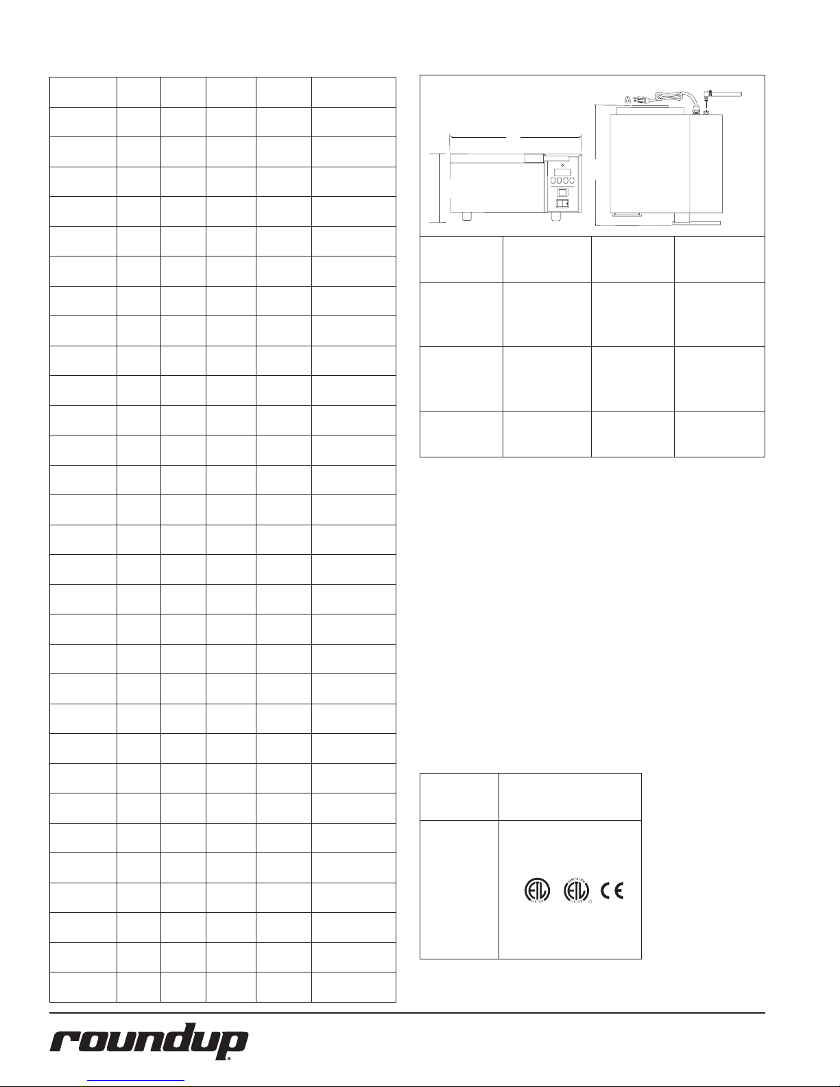
SPECIFICATIONS
A
S
D
L
I
S
T
E
CM
O
I
N
N
I
T
A
T
C
T
I
S
L
US
E
D
D
L
I
S
T
E
C US
I
N
T
E
R
T
E
K
Model &
Mfg. No.
DFW-100
9100101
DFW-100
9100102
DFW-100
9100103
DFW-150
9100104
DFW-150
9100105
DFW-150
9100106
DFW-150
9100107
DFW-200
9100111
DFW-200
9100112
DFW-200
9100113
DFW-250
9100114
DFW-250
9100115
DFW-250
9100116
DFW-200
9100118
DFWT-100
9100121
DFWT-100
9100122
DFWT-100
9100123
DFWT-150
9100124
DFWT-150
9100125
DFWT-150
9100126
DFWT-150
9100128
DFWT-200
9100131
DFWT-200
9100132
DFWT-200
9100133
DFWT-250
9100134
DFWT-250
9100135
DFWT-250
9100136
DFWF-250
9100146
DFWF-250
9100147
DFWF-250
9100156
Volts Watts Amps Hertz
120 1800 15 50/60
120 1500 12.5 50/60
230 2800 12.2 50/60
120 1800 15 50/60
120 1500 12.5 50/60
230 2800 12.2 50/60
230 2800 12.2 50/60
120 1800 15 50/60
120 1500 12.5 50/60
230 2800 12.2 50/60
120 1800 15 50/60
120 1500 12.5 50/60
230 2800 12.2 50/60
230 2800 12.2 50/60
120 1800 15 50/60
120 1800 15 50/60
230 2800 12.2 50/60
120 1800 15 50/60
120 1800 15 50/60
230 2800 12.2 50/60
230 2800 12.2 50/60
120 1800 15 50/60
120 1800 15 50/60
230 2800 12.2 50/60
120 1800 15 50/60
120 1800 15 50/60
230 2800 12.2 50/60
208 3300 15.8 50/60
208 3300 15.8 50/60
230 3300 14.3 50/60
Plug
Description
NEMA 5-15P
15 Amp, 120 Volt
NEMA 5-15P
15 Amp, 120 Volt
CEE 7/7
16 Amp. 250 Volt
NEMA 5-15P
15 Amp, 120 Volt
NEMA 5-15P
15 Amp, 120 Volt
CEE 7/7
16 Amp. 250 Volt
NEMA 5-15P
15 Amp, 120 Volt
NEMA 5-15P
15 Amp, 120 Volt
NEMA 5-15P
15 Amp, 120 Volt
CEE 7/7
16 Amp. 250 Volt
NEMA 5-15P
15 Amp, 120 Volt
NEMA 5-15P
15 Amp, 120 Volt
CEE 7/7
16 Amp. 250 Volt
CEE 7/7
16 Amp. 250 Volt
NEMA 5-15P
15 Amp, 120 Volt
NEMA 5-20P
20 Amp. 120 Volt
CEE 7/7
16 Amp. 250 Volt
NEMA 5-15P
15 Amp, 120 Volt
NEMA 5-20P
20 Amp. 120 Volt
CEE 7/7
16 Amp. 250 Volt
IEC-309
16 Amp. 250 Volt
NEMA 5-15P
15 Amp, 120 Volt
NEMA 5-20P
20 Amp. 120 Volt
CEE 7/7
16 Amp. 250 Volt
NEMA 5-15P
15 Amp, 120 Volt
NEMA 5-20P
20 Amp. 120 Volt
CEE 7/7
16 Amp. 250 Volt
NEMA 6-20P
20 Amp. 250 Volt
NEMA 6-20P
20 Amp. 250 Volt
CEE 7/7
16 Amp. 250 Volt
A
B
C
Model No.
Width
(A)
Depth
(B)
Height
(C)
DFW-100
DFW-200
DFW-150
16 1/2"
(419 mm)
17 1/4"
(438 mm)
8 1/4"
(209 mm)
DFW-250
DFWT-100
DFWT-200
DFWT-150
20"
(508 mm)
17 1/4"
(438 mm)
8 1/4"
(209 mm)
DFWT-250
DFWF-250
26 7/8"
(682 mm)
17 1/4"
(438 mm)
9 7/16"
(240 mm)
SHIPPING WEIGHT
DFW-100 Series 40 lbs (18.2 kg)
DFW-200 Series 40 lbs (18.2 kg)
DFWT-100 Series 54 lbs (24.5 kg)
DFWT-200 Series 54 lbs (24.5 kg)
DFWF-250 Series 75 lbs (33.6 kg)
CAPACITIES
DFW Series 2-7/8” (7.3 cm) Deep Half-size steam table pan
DFWT Series 2-7/8” (7.3 cm) Deep Two-third-size steam
table pan
DFWF Series 4” (10.2 cm) Deep Full-size steam table pan
Model &
Mfg. No.
DFW-100
DFW-150
DFW-200
DFW-250
DFWT-100
DFWT-150
DFWT-200
DFWT-250
DFWF-250
Agency Approvals
4
P/N 1010678 Rev. K 08/12
Page 5
INSTALLATION
NOTE: When placing the unit, make sure
to provide at least 3 inches of space on
all sides of the unit.
1. Remove unit and all packing materials
from shipping carton.
2. The unit should come with the items
listed below:
• Owner’s Manual
• Authorized Service Agency Directory
• Inlet Hose Assembly (DFW/DFWT/
DFWF-200/250 only).
NOTE: If any parts are missing or damaged, contact Antunes Technical Service
IMMEDIATELY at 1-877-392-7854 or
1-630-784-1000.
3. Remove all packing materials and
protective coverings from the unit.
4. Remove and wash the Pan, Trivet, and
Diffuser in soap and water. Rinse with
clean water and allow to air dry.
NOTE: The steam generator surface
(Figure 6) will have a white coating of
artificial lime deposits. This coating is
necessary for steaming characteristics.
5. Wipe all surfaces of the unit with a
hot damp cloth.
NOTE: Do NOT use a dripping wet cloth.
Wring out before use.
6. Re-install Pan, Trivet, and Pan Diffuser.
When placing the unit into service, pay attention to the following guidelines.
• Make sure to provide at least 3 inches
of space on all aides of the unit.
• Make sure the power switch is off and
the unit is at room temperature before
plugging in the power cord.
• Do not block or cover any openings
on the unit.
• Do not immerse the power cord or
plug in water.
• Keep the power cord away from
heated surfaces.
• Do not allow the power cord to hang
over edge of table or counter.
Plug the power cord into the appropriate
power outlet. Refer to the specification
plate for the proper voltage.
1. With the power off, place the unit on a
sturdy, level surface.
2. Ensure the line voltage corresponds to
the stated voltage on the specification
label and power cord warning tag.
3. Connect the unit to the power supply.
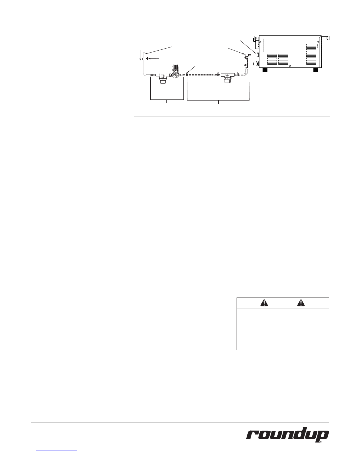
Connect Quick
Disconnect
Cold
Water
Flow
Flexible Nylon Braided
1/4 " I.D. Tubing (Not Supplied)
Shut Off Valve
(Not Supplied)
Water Pressure Regulator
& Strainer Assy. (P/N 7000314)
Disconnect
Worm
Clamp
Inlet Hose & Strainer
Assy. (Supplied)
Quick
Insert
Insert Here
Figure 1. Connecting Water Supply to DFW/DFWT/DFWF-200/250
PLUMBING
DFW models are designed to use cold tap
water. Distilled water may be used to reduce
calcium/mineral deposit buildup and reduce
maintenance costs.
MODELS DFW/DFWT-100/150
The DFW/DFWT-100/150 models have a selfcontained water tank. To fill the tank:
1. Open the tank cover on the top of
the unit.
NOTE: Make sure the filter inside the tank
is installed properly.
2. Pour in cold tap water. The tank will
hold approximately 3 quarts (2.81
liters). Do not overfill the tank.
3. Close the tank cover.
MODELS DFW/DFWT/DFWF-200/250
The DFW/DFWT/DFWF-200/250 models require
a direct cold water hookup. A water inlet hose
and strainer assembly (Figure 1) is supplied.
Incoming water is controlled by a normally
closed solenoid valve located inside the
steamer’s electrical housing.
1. Turn off the water valve (not supplied)
that provides water to the unit.
2. Connect the 1/4" (6.5 mm) ID flexible
tubing to the outlet side of the water
pressure regulator and secure using
the worm clamp.
NOTE: A Water Pressure Regulator must
be installed. Failure to do so will result
in poor steaming and possible flooding.
For a single steamer, use Water Pressure
Regulator P/N 7000314. For two adjacent
steamers, use Water Pressure Regulator
P/N 7000235.
3. Turn the water valve on.
4. Over a bucket, press and hold
the white plastic tip on the Quick
Disconnect Insert (Figure 1) until a
good, steady water flow is noted (this
will purge all air out of the line).
5. Release and note the pressure on the
water pressure regulator gauge. It
should read 20-25 psi. Adjust the pressure by pulling the black knob upwards
and turning it clockwise to increase
or counter-clockwise to decrease the
water pressure. Push the knob down to
lock it in place.
NOTE: When adjusting the knob, you must
relieve the existing pressure by pressing
the plastic tip on the Quick Disconnect
Insert for 3 seconds. This allows the newly
set pressure to register on the gauge.
Repeat this until the gauge reads 20–25
psi.
6. Push the Quick Disconnect Insert into
the fitting at the rear of the unit until
it clicks into place (Figure 1).
CAUTION
Water pressure must not exceed 30 psi (2.1
kg/cm2 or 207 kPa). Higher water pressures
may cause poor performance or flooding.
To reduce water pressure, install a water
pressure regulator, and set water pressure to
20–25 psi (1.4–1.7 kg/cm2 or 138–172 kPa).
P/N 1010678 Rev. K 08/12
5
Page 6
POWER
GENERAL INFORMATION
READY
UP DOWN PROGRAM START/STOP
POWER
ALL MODELS
When the OPERATE button is pressed, power
is supplied to the water pump (Water Tank
models) or solenoid valve (Direct Water
Hookup models). The pump/solenoid operates and water sprays onto the heated steam
generator. The water flashes immediately into
steam and steams the product.
TIMER MODELS DFW/DFWT/DFWF–
150/250 EXCEPT DFWF-250 WITH
MFG. NO. 9100147
On Timer Models, one of two operational modes
can be used: Single Shot or Timed Cycle.
Single Shot
The OPERATE button is pressed and released
to initiate a single steam shot. The Control
Board applies power to the water pump/solenoid and a shot of steam occurs.
Timed Cycle
The control is used to set the desired steam
time (up to 99 minutes, 59 seconds). When
the START/STOP button (Figure 3) is pressed,
the Control Board applies power to the water
pump/solenoid at regular intervals for the
duration of the displayed cycle time. The display counts down to zero, sounds an audible
signal when the cycle is complete, and then
reverts back to the original programmed cycle
time. The unit is ready for the next cycle when
the green ready light is on.
IMPORTANT: Timer Models are factory programmed for the following recommended
settings:
• Total Cycle Time = [15.00] (15 minutes)
(Range: 3 sec. to 99 mins 59 secs)
• Shot Interval Time (SHO) = [00:20] (20
seconds)
(Range: 3 secs to 5 mins 59 secs). 20
seconds is recommended.
• Water Volume (H2O) =
DFW/DFWT/DFWF-250 - [0_50]
DFW/DFWT-150 - [0_80]
(Range: 0.10 seconds to 2.50)
The above settings convert approximately 3/4
oz. (25 milliliters) of water into to steam every
20 seconds for 15 minutes. To change any of
these settings see the appropriate Operating
Instructions for your specific unit.
WARNING
To avoid injury, be careful when opening top
cover. Be sure to allow steam to escape
before putting hands or face over the
steamer.
OPERATING INSTRUCTIONS
NON-TIMER MODELS
1. Turn the power on (Figure 2).
2. Allow the unit to preheat for approximately 30 minutes.
NOTE: Do NOT push the OPERATE button
during warm-up.
3. Open the top cover and place the
product to be steamed onto the trivet,
then close the cover.
4. Press the OPERATE button for 1 second then release and wait 20 seconds
for the steam to penetrate the product. Repeat if product requires more
steam.
NOTE: Pressing and holding the OPERATE
button for longer than 1 second at a time,
and/or too often (before 20 seconds), will
flood out the Generator surface (Figure 6)
and result in poor steaming.
5. Remove steamed product.
TIMER MODELS
1. Turn the power on (Figure 3).
2. Allow the unit to preheat for approximately 30 minutes.
IMPORTANT: The flashing green Ready
Light will become steady when the unit is
up to temperature and ready to be used.
IMPORTANT: Do NOT push the OPERATE
button during warm-up. The flashing
green Ready Light indicates unit is not up
to temperature.
3. Open the top cover and place the
product to be steamed onto the trivet,
then close the cover.
4. Single Shot: Press the OPERATE but-
ton for 1 second then release and wait
20 seconds for the steam to penetrate
the product.
Timed Cycle: Press the START/STOP
button to begin the steaming cycle.
Display will count down to zero.
5. Remove steamed product.
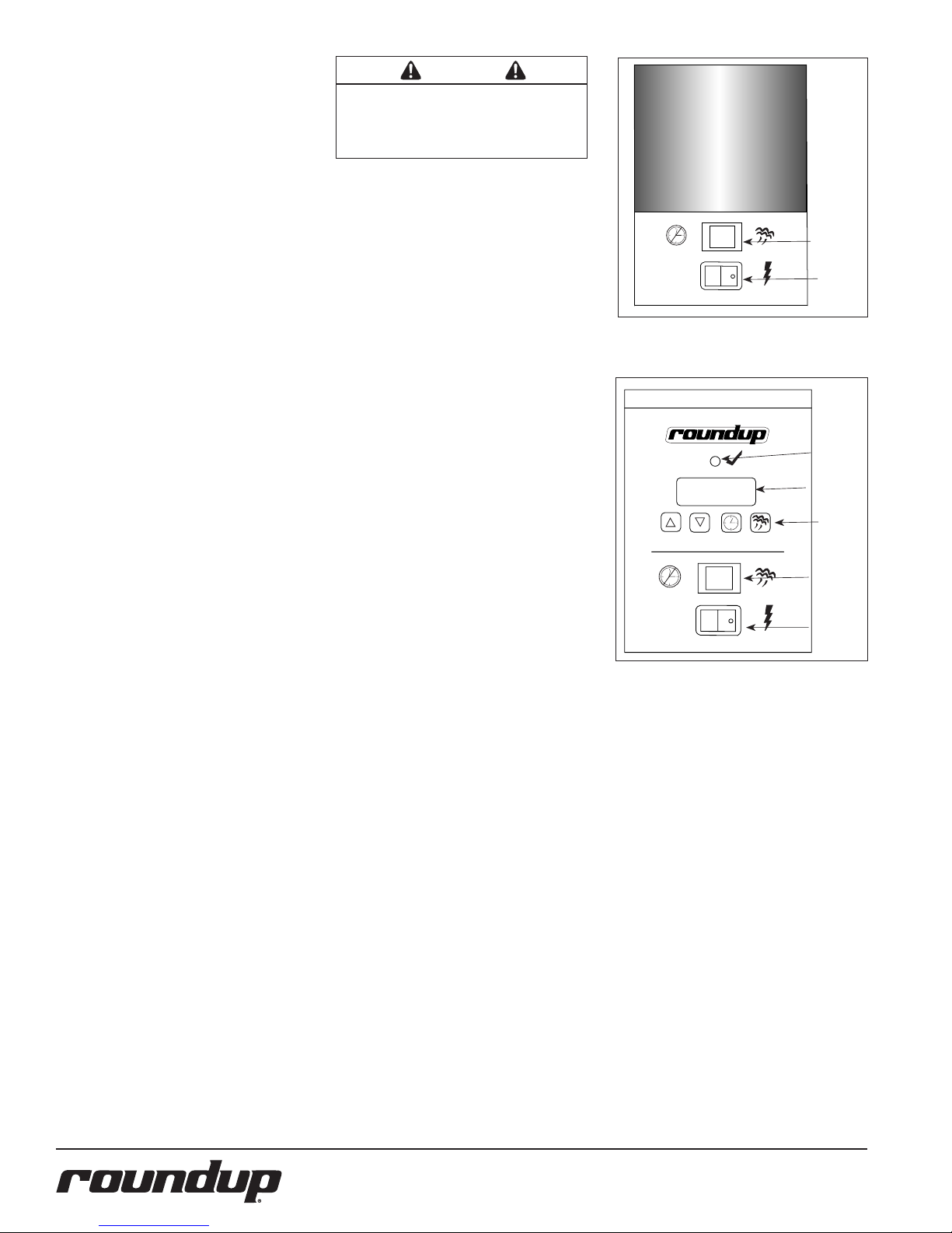
Figure 2. Control Panel
(Non-Timer Models)
Figure 3. Control Panel
(Timer Models)
Operate
Button
Power
Switch
Ready Light
Message
Display
Start/Stop
Button
Operate
Button
Power Switch
6
P/N 1010678 Rev. K 08/12
Page 7
PROGRAMMING
READY
UP DOWN PROGRAM START/STOP
POWER
1500
READY
UP DOWN PROGRAM START/STOP
POWER
15
READY
UP DOWN PROGRAM START/STOP
POWER
00
READY
UP DOWN PROGRAM START/STOP
POWER
SHO
READY
UP DOWN PROGRAM START/STOP
POWER
00
READY
UP DOWN PROGRAM START/STOP
POWER
20
READY
UP DOWN PROGRAM START/STOP
POWER
H2O
READY
UP DOWN PROGRAM START/STOP
POWER
0_80
CYC (Total Cycle Time) refers to the total
amount of steaming time set for the product.
SHO (Shot Interval Time) is the time set
between shots of steam during a complete
cycle.
H2O Setting (Steam Shot Time) is used to
adjust the water volume used during each
pump/solenoid operation.
The amount of steam produced by your
Deluxe Food Warmer (steamer) depends on
the amount of water sprayed onto the steam
generator.
Flooding of the Generator may occur if the
H2O setting is set too high. To prevent this
from occurring, the Shot Interval Time (SHO)
may be increased to allow more time for
generator heat recovery. Adjustments should
be made to both values to determine the optimum settings for your cooking needs.
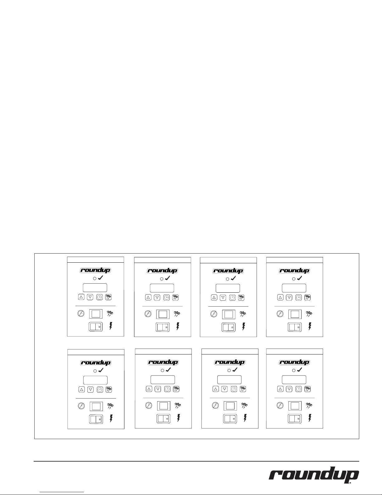
To program the control, refer to Figure 4 and
use the following procedure in sequence:
1. Turn the power on. The display shows
the factory programmed Total Cycle
Time in minutes and seconds (Item A,
Figure 4).
2. Press and release the PROGRAM
button to change the control from
Operation to Program mode.
3. To change the Total Cycle Time in minutes, use the UP or DOWN ARROW
buttons to change the time (Item B,
Figure 4).
4. Press and release the PROGRAM button again and use the UP or DOWN
ARROW buttons to change the Total
Cycle Time in seconds (Item C, Figure
4).
5. To change the SHO factory settings,
make sure the control is in Program
mode, then press and hold the two
ARROW buttons simultaneously for
1-2 seconds and then release. SHO will
be displayed (Item D, Figure 4).
6. Press and release the PROGRAM button and use the UP or DOWN ARROW
buttons to change the SHO setting in
seconds (Item E, Figure 4).
NOTE: 20 seconds is recommended.
7. Press and release the PROGRAM button again and use the UP or DOWN
ARROW buttons to change the SHO
setting in minutes (Item F, Figure 4).
NOTE: 00 minutes is recommended.
8. Press and release the PROGRAM
button again and “H2O” is displayed
(Item G, Figure 4).
9. To change the H2O setting, press and
release the PROGRAM button again to
display the setting (Item H, Figure 4).
Use the UP or DOWN ARROW buttons
to increase or decrease the time.
NOTE: Recommended settings are :
• DFW/DFWT/DFWF-250 [0_50]
• DFW/DFWT-150 [0_08]
10. Press either the START/STOP or
OPERATE button to store the changes
and to exit the Program mode.
NOTE: The START/STOP or OPERATE button
may be pressed at any time during programming to store the changes and exit
the Program mode.
NOTE: If no change is made within 5 seconds at any time during the programming
process, all changes made up to that point
are stored in memory and the control
reverts to the Operation mode.
A. Total Cycle Time
E. SHO Time Seconds E. SHO Time Minutes
P/N 1010678 Rev. K 08/12
B. Total Cycle Minues C. Total Cycle Seconds
G. H2O Cycle G. H2O Setting
Figure 4. Control Programming Sequence
7
D. SHO Cycle
Page 8
Reset Button
Cap
DIAGNOSTIC LEDS
TIMER MODELS
This control board has 4 diagnostic LEDs
described below.
CAUTION
Do not use a sanitizing solution or abrasive
materials. The use of these may cause damage to the stainless steel finish.
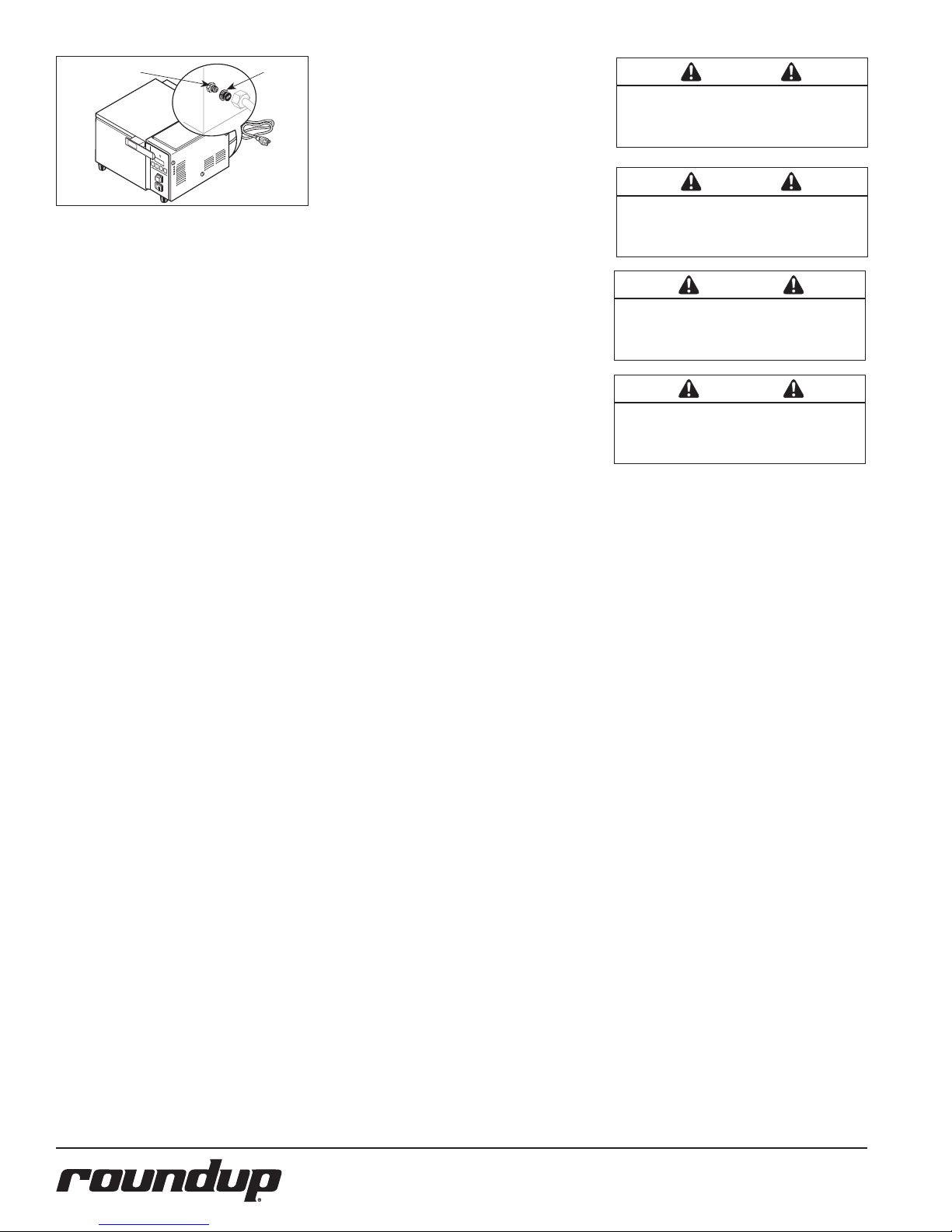
Figure 5. Hi-Limit Reset Button
HI-LIMIT RESET BUTTON
A hi-limit thermostat will turn off electrical
power to the heater and control circuits if the
unit overheats. To reset the thermostat, allow
sufficient time (about 45 minutes) for the unit
to cool down, remove the cap and press the
red reset button located on the rear of the
unit (Figure 5).
If the unit requires continuous resetting,
contact your Authorized Service Agency.
FAULT CODES
When the programming parameters for
Minutes, Seconds, SHO, or H2O have been
inadvertently changed to a setting above or
below their limits, the unit displays the “ERR”
fault code. If this fault code appears, you
must clear these settings using the following
procedure.
1. Turn the power off.
2. Press and hold the PROGRAM and
START/STOP buttons simultaneously.
3. Turn the unit on while holding the
buttons. Release the buttons when the
unit stops beeping.
NOTE: Repeat steps 1 through 3 if the
unit still displays the “ERR” fault code.
4. The display will now register 15:00.
NOTE: It is recommended that the SHO
and H2O settings be adjusted to the
recommended settings shown in the
Programming section of this manual.
Green (Program): When lit, indicates the unit
is in Program mode.
Yellow (Audio): When lit, indicates 10-15
VDC is being supplied to the audio signal. The
audio signal will sound and the LED will be lit
for approximately 3 seconds.
Red (Heat): When lit, indicates the unit is
calling for heat by supplying 10-15 VDC to the
solid state relay. When off, indicates the generator surface is up to temperature.
Green (H2O): When lit, indicates that 24
VAC is being supplied to operate the solenoid
valve used in DFW/DFWT/DFWF-250 units or
to the water pump used in the DFW/DFWT150 units.
NOTE: This LED is only lit for approximately 1 second.
NON-TIMER MODELS ONLY
This control board has 2 diagnostic LEDs
described below.
Yellow (CR2): If lit, indicates the thermistor
probe is disconnected or open. The thermistor
should be 100k ohms +/- 2% at room temperature.
NOTE: The unit will not call for heat. This
LED should NOT be lit during normal
operation.
Red (CR4): When lit, indicates that the unit is
calling for heat by supplying 15-20 VDC to the
solid state relay. When off, indicates that the
Generator surface is up to temperature.
CAUTION
If a chemical cleaner is used, be sure it is
safe to use on cast aluminum. Observe all
precautions and warnings on product label.
WARNING
Turn the power off, unplug the power cord, and
all the unit to cool down before performing
any service or maintenance.
WARNING
Be sure to follow all the precautions, procedures, and safety steps listed in the Important
Safety Information section of this manual.
DAILY MAINTENANCE
NOTE: Frequency of cleaning is determined by water conditions, usage and
water filter systems.
1. Turn the power off, unplug the power
cord, and allow the unit to cool down
before proceeding.
2. Check the water pressure regulator
gauge (DFW/DFWT/DFWF-200/250
units only) and verify that it reads
20–25 psi (1.4–1.7 kg/cm2 or 138–
172 kPa). If not, adjust the water pressure as described in the Installation
section of this manual. Check the
rear water Quick Disconnect Fitting
and Hose Clamp for leakage. Tighten
clamps or replace parts if needed.
3. Remove the trivet and pan (Figure 6).
4. Wash items in hot, soapy water and
then rinse and wipe dry.
5. Wipe down the top cover, gasket, and
the entire exterior of the unit (Figure
6) with a clean, hot, damp cloth (not
dripping wet) and wipe dry.
6. Re-install diffuser, pan and trivet.
NOTE: Allow top cover to remain open
overnight.
NOTE: Failure to properly clean and dry
the above mentioned items may result
in the accumulation of water/moisture
overnight. This may lead to permanent
damage to the equipment’s finish and its
accessories. This damage is not covered
by warranty.
8
P/N 1010678 Rev. K 08/12
Page 9
Trivet
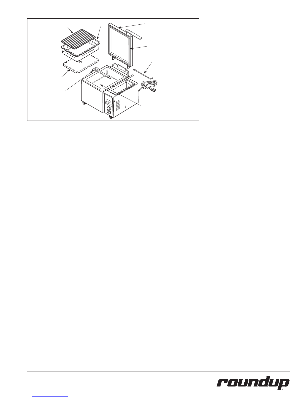
Diffuser
Spray
Tube
Assy.
Pan
Top Cover
Assy.
Gasket
Hinge Pin
Steam
Generator
Surface
Figure 6. Deluxe Food Warmer Components (DFW-150 Shown)
MONTHLY MAINTENANCE
CLEAN SPRAY TUBE AND STEAM
GENERATOR
The Deluxe Food Warmer utilizes an open
Steam Generator. Water sprayed onto the
generator surface flashes into steam immediately, but the minerals in the water do not
steam. They stay on the generator surface. A
small amount of calcium/mineral deposits are
needed for proper operation, but a buildup
of excessive calcium/mineral deposits causes
poor steaming efficiency and excessive
moisture (wet steam), which will eventually
severely retard the steaming action.
1. Turn the power off, unplug the power
cord, and allow the unit to cool down
before proceeding.
2. Perform the Daily Cleaning, but do not
reassemble the unit.
3. Remove the spray tube (Figure 6) by
lifting the loose end and pulling it out
of the generator hole.
4. Slide the metal cover off of the spray
tube, take a paper clip and clear out
all of the tube’s holes.
5. Gently wash the tube under running
water to clear the deposits out of the
loose end. Reattach the cover onto
the tube.
NOTE: Do not bend the spray tube. Any
bends in the tube will result in permanent
damage.
6. Use a scraper or spatula to remove the
excessive calcium/mineral buildup from
the generator surface (Figure 6).
7. Thoroughly wipe the generator with
a damp cloth to remove any loose
buildup and reassemble the unit.
NOTE: If deposits are still excessive and/
or difficult to remove, refer to Steps 1
through 6 below.
1. Pour delimer solution (not supplied)
onto the generator surface. Follow the
delimer manufacturer’s instructions for
proper mixture and use.
2. Using a sponge or a dry towel, remove
the delimer solution from the generator surface and then rinse the surface
with clean water.
To ensure proper steaming characteristics,
some calcium/mineral deposits must be present on the generator surface. If, during cleaning, the surface does become free of calcium/
mineral deposits, add plain tap water to the
surface and allow it to boil off. If necessary,
repeat this process to formulate a thin coating
of calcium/mineral deposits.
In soft water areas. it may be necessary to
add a small amount of lime to the generator
surface to season it. This will ensure proper
steaming characteristics by producing a thin
coating of calcium/mineral deposits on the
Generator surface.
Seasoning mixture consists of 3/4 ounces (25
ml/25 cc) baking soda, 3/4 ounces (25 ml/25
cc) lime mixed with 1 quart (950 ml/950 cc) of
water. Stir mixture and pour 1/4” deep onto
the hot Generator surface. After mixture is converted to steam, the remaining loose powder
can be removed.
3. Plug the power cord into the appropriate outlet.
4. Turn the power on and allow the unit
to warm up for approximately 30
minutes.
5. Push and release the OPERATE button
several times to purge any remaining
delimer residue from the generator
surface.
6. Turn the power off, reinstall all parts
and accessories, and return the unit to
service.
P/N 1010678 Rev. K 08/12
9
Page 10
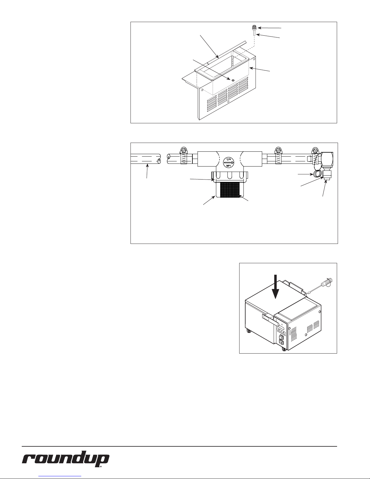
MONTHLY MAINTENANCE
WATER TANK FILTER
(DFW/DFWT-100/150 ONLY)
The water tank filter is used to prevent particles or food products from entering and
damaging the water pump. Inspect and clean
this filter monthly or more regularly using the
following procedure.
1. Turn the power off, unplug the power
cord, and allow the unit to cool down
before proceeding.
2. Open the slide door (Figure 7).
3. Remove the water tank filter, located
inside the tank, by pulling it upwards
and out of the bottom hole.
4. Clean the filter by running it under tap
water. Replace the water tank filter if
the screen is torn or damaged.
5. Reinstall the filter stem into the bottom hole of the tank (Figure 7).
6. Fill the water tank and test the unit.
Tubing
Tank Cover
Bottom Hole
of Water
Tank
O-ring
Water Tank Filter
Filter Stem
Access Cover
with Tank
(dotted line)
Figure 7. Water Tank Filter
Spare O
Rings (3)
O Ring
WATER STRAINER
(DIRECT WATER HOOKUP MODELS)
The water strainer protects your equipment
from any foreign debris in the water line that
could damage the unit’s solenoid (causing the
unit to leak/flood) To ensure proper and consistent steaming results, check the water pressure regulator and strainer cup regularly. If the
pressure on the gauge has dropped, check the
strainer cup and clean out the accumulated
debris as follows:
1. Shut off the water supply valve to the
unit, unscrew the strainer cup, and carefully remove the mesh strainer Screen.
2. At the sink, gently flush all of the
accumulated debris from the strainer
cup and mesh strainer screen. Be
especially careful not to damage the
mesh strainer screen.
3. Carefully place the mesh strainer
screen into its seat at the bottom of
the strainer cup and confirm that the
orange O-ring is properly seated in its
place before screwing the strainer cup
and top back together.
4. Purge the air out of the strainer and
tubing by disconnecting the male
quick disconnect insert from the
equipment and, over a bucket, push
the white plastic tip in until there is
good water flow.
5. Replace damaged or worn parts.
6. Verify that the water pressure regulator is set to 20–25 psi (1.4–1.7 kg/
cm2 or 138–172 kPa).
Mesh
Strainer Cup
NOTE: If the Male Quick Disconnect Fitting leaks water while it is engaged
into the rear of the Steamer, then the O-ring must be replaced. Three (3)
spare O-Rings are supplied.
Screen
Figure 8. Inlet Hose Assembly
TOP COVER ADJUSTMENT
It is normal for a small amount of steam to
escape around the front and sides of the top
cover. However, excessive steam may indicate
the top cover gasket is worn and/or the cover
is out of adjustment or damaged.
1. With the top cover closed, loosen the
four rear hinge bracket screws (Figure
9) one turn only.
2. Push down on the top cover heavily
(Figure 9). This ensures the gasket is
seated squarely around the Generator.
While maintaining the downward
pressure, re-tighten the screws.
10
Figure 9. Top Cover Adjustment
P/N 1010678 Rev. K 08/12
Male Quick
Disconnect
Insert
Press Firmly On The Top
Cover
Page 11
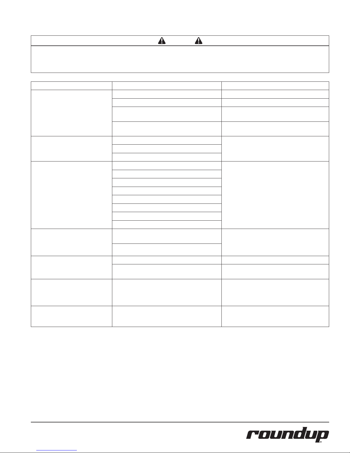
TROUBLESHOOTING
WARNING
To avoid possible personal injury and/or damage to the unit, inspection, test, and repair of electrical equipment should be performed by qualified
service personnel. The unit should be unplugged when servicing, except when electrical tests are required. Use extreme care during electrical circuit
tests. Live circuits will be exposed. If the troubleshooting steps listed below do not solve your machine’s problem, contact an Authorized Service
Agency for further assistance.
Problem Possible Cause Corrective Action
Control Display is blank (Power is on
but indicator light is off)
Timer Models Only.
Control Display is blank (Power is and
indicator light is on).
Timer Models Only
Unit does not heat up (Power is on
and indicator light is on).
The unit’s main electrical panel circuit
breakers trips.
Water leaking inside electrical housing. Pinhole leak in robber hoses (DFW/DFWT-100/150). Replace hoses.
Water leaking at Male Quick
Disconnect Fitting while it is engaged
into steamer
(DFW/DFWT/DFWF-200/250)
“ERR” appears on the Control Display
(Timer Models only).
The power cord is not correctly plugged in. Plug the power cord into the appropriate outlet.
The power cord and/or electrical plug is damaged. Inspect electrical wire, plug, and receptacle.
The main electrical panel circuit breaker is off or has
tripped.
Power Switch is inoperable. Contact your maintenance person or Authorized
Control Board is inoperable. Contact your maintenance person or Authorized
Transformer is inoperable.
Loose, burnt, or broken wires in circuit.
Hi-Limit Thermostat is tripped or inoperable. Reset the Hi-Limit Thermostat according to the
Transformer is inoperable.
Solid State Relay is inoperable
Thermocouple is inoperable (Timer Models Only).
Control Board is inoperable.
Steam Generator is inoperable.
Loose, burnt, or broken wires in circuit.
Thermistor is inoperable (Non-Timer Models Only).
Damaged receptacle, plug, or cord or a loose connection or an internal component failure.
Circuit breaker is overloaded.
Loose or damaged water line tubes and/or fittings
inside electrical housing.
The O-ring on the Male Quick Disconnect is damaged.
Programming and or SHO and H2O values were
adjusted/changed improperly (Timer Models Only).
Reset circuit breaker. Contact your maintenance
person or Authorized Service Agency if it trips again.
Service Agency for service.
Service Agency for service.
Operations section of this manual. If the Hi-Limit
Thermostat requires continuous resetting, contact
your Authorized Service Agency for service.
Turn power off, allow unit to cool to room temperature, and then restart the unit. Contact your maintenance person or Authorized Service Agency if the
condition repeats.
Tighten or replace tubes and/or fittings.
Replace O-ring. Refer to the Maintenance section of
this manual (Figure 8).
Reset the Control Board as described in the
Programming section of this manual. See Fault
Codes.
P/N 1010678 Rev. K 08/12
11
Page 12
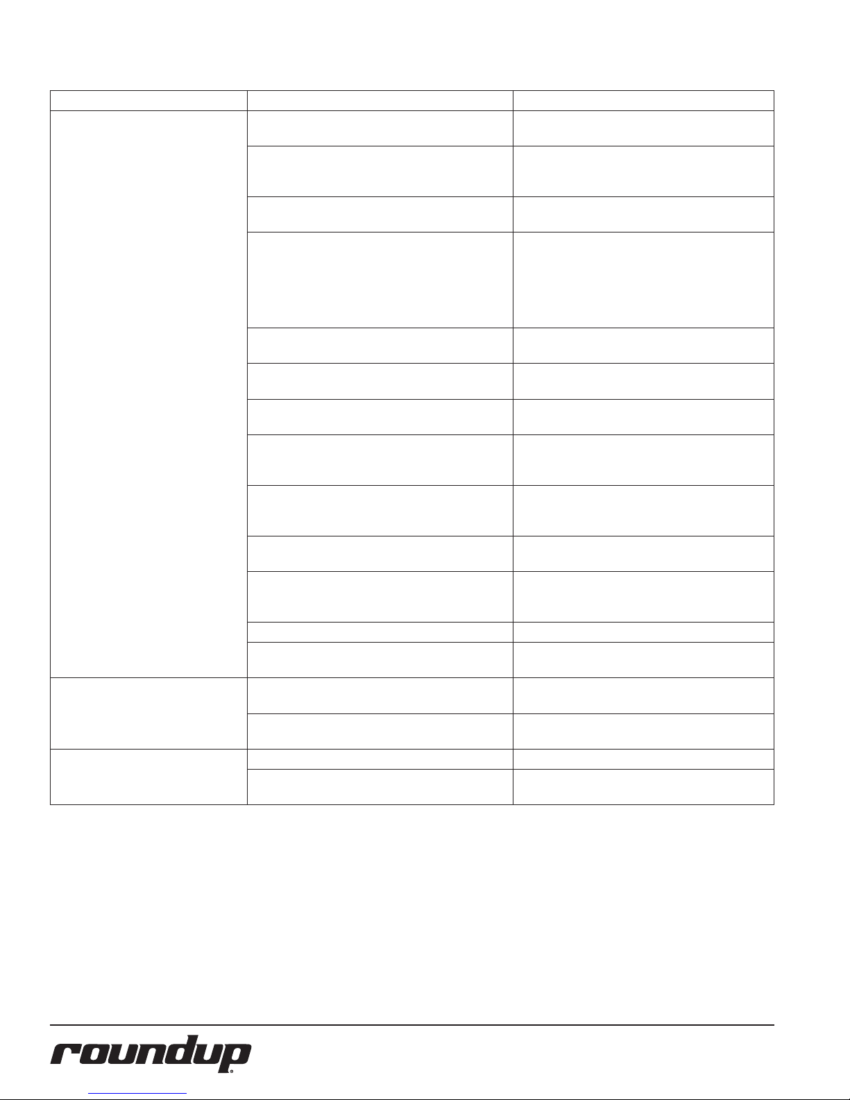
TROUBLESHOOTING (continued)
Problem Possible Cause Corrective Action
Unit heats but there is little or no
steam produced and/or
The product requires more steaming
than usual.
Excessive condensation in Food
Compartment.
Excessive Steam escapes from front or
sides of steamer.
Water Line Valve is closed (DFW/DFWT/DFWF200/250).
Filter Strainer and/or Spray Tube is restricted. Check and clean the Filter Strainer and Spray Tube
Quick Disconnect is not fully engaged at the rear of
the unit or is damaged (DFW/DFWT/DFWF-200/250).
Low or no water pressure in the water line (DFW/
DFWT/DFWF-200/250).
Improper water pressure to unit (DFW/DFWT/DFWF200/250).
Unit is not being cleaned properly (daily/monthly). Clean the unit daily and monthly as described in the
Programming and/or SHO, H2O values were adjusted/
changed improperly (Timer Models only).
Insufficient or excessive calcium/mineral deposits on
the Generator surface.
Generator surface is bare. The Generator surface must have a thin coating of
The Water Pump’s rubber hoses are pinched or
kinked (DFW/DFWT-100/150).
Top Cover Gasket is worn and/or cover is out of
adjustment.
Generator Diffuser is missing. Install Generator Diffuser or replace if missing.
Generator surface temperature is too low. Verify that the Generator surface temperature is
Water pressure is too high (DFW/DFWT/DFWF200/250).
Programming and or SHO and H2O values were
adjusted improperly (Timer Models only).
Worn or damaged Top Cover Gasket. Replace Top Cover Gasket.
Top Cover out of adjustment. Adjust Top Cover according to the Maintenance
Check that the Water Line Valve is open.
as described in the Maintenance section of this
manual.
Remove and re-engage the Quick Disconnect firmly
until it clicks into place. Replace if damaged.
Remove the Quick Disconnect Insert from the rear
of the unit. While holding over an empty cup, press
the white plastic tip. Strong, steady water flow
should be noted. If so, re-engage firmly into unit. If
not present or pressure is low, contact your maintenance person or plumber.
Verify that a Water Pressure Regulator is installed
and set to 20–25 psi.
Maintenance section of this manual.
Reprogram the SHO and H2O values as described in
the Programming section of this manual.
Verify that a thin layer of calcium/mineral deposits
is present on the Generator surface. Refer to the
Maintenance section of this manual.
calcium/mineral deposits for proper steaming. Refer
to the Maintenance section of this manual.
Straighten and reposition the rubber hoses.
If noticeable steam escapes around the Cover,
replace the gasket and/or adjust the Cover according to the Maintenance section of this manual.
380°F–420°F (193°C–215°C).
Verify that the Water Pressure Regulator is set to
20–25 psi. Adjust accordingly.
Reprogram the SHO and H2O values as described in
the Programming section of this manual.
section of this manual.
12
P/N 1010678 Rev. K 08/12
Page 13
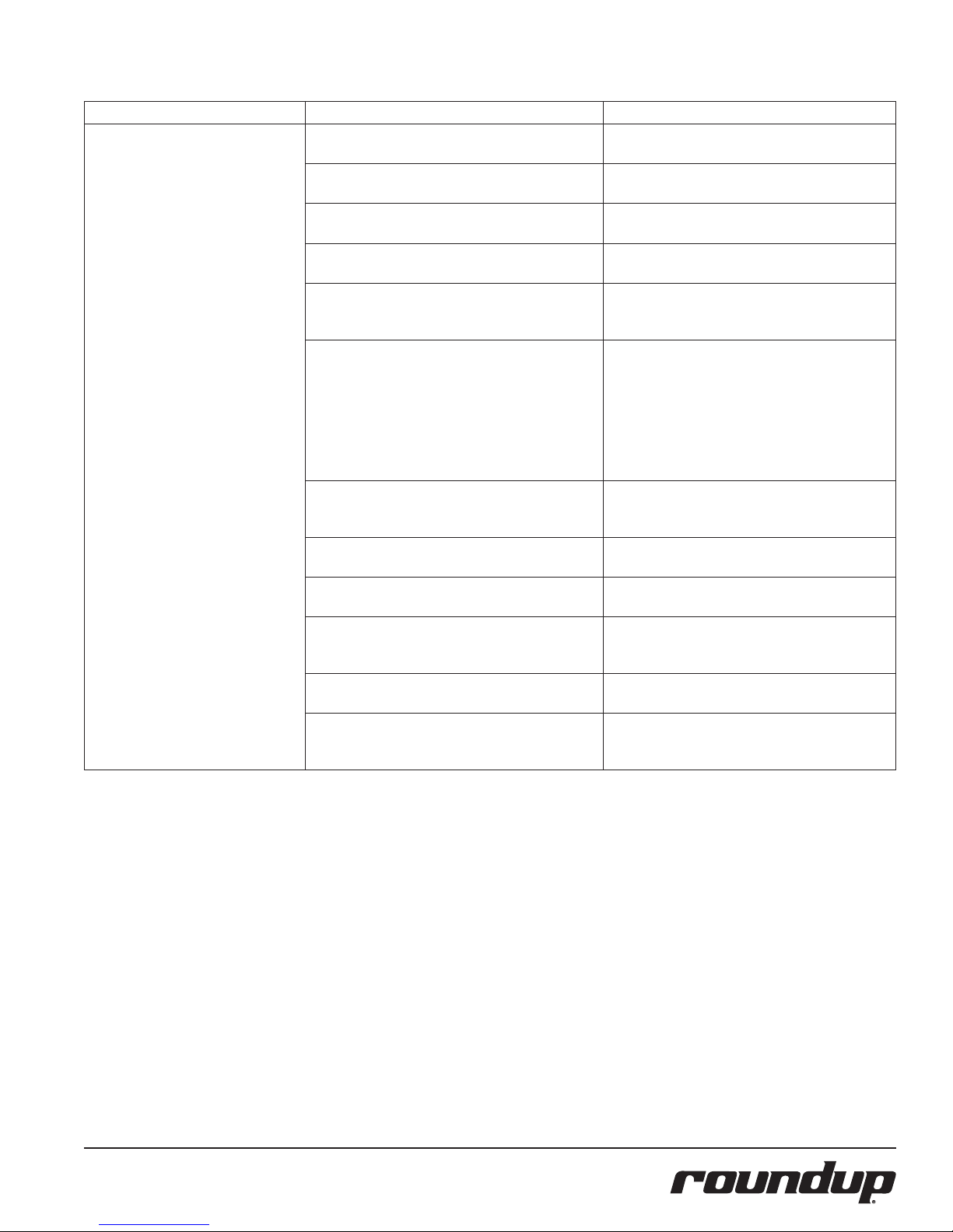
TROUBLESHOOTING (continued)
Problem Possible Cause Corrective Action
Steam Generator’s surface becomes
flooded (fills with excess water).
Insufficient pre-heat time. Remove excess water from the Generator surface
The Green Momementary Switch is pressed for longer than 1 second.
Water Pressure Regulator is not installed (DFW/
DFWT/DFWF-200/250).
Water pressure is too high (DFW/DFWT/DFWF200/250).
Programming and/or SHO and H2O values were
adjusted or changed improperly (Timer Models
only).
Solenoid Valve is leaking due to debris trapped inside
the plunger (DFW/DFWT/DFWF-200/250).
The Water Pump and/or its Check Valves are clogged
or damaged.
Improper Daily/Monthly cleaning. Follow the Daily/Monthly cleaning procedures
The Generator surface temperature is too low. Verify that the Generator surface temperature is
Insufficient or excessive calcium/mineral deposits on
the Generator surface.
There is no pre-strainer or filter on the water line
(DFW/DFWT/DFWF-200/250).
Solenoid Valve is installed incorrectly (DFW/DFWT/
DFWF-200/250).
and allow the unit 30 minutes of pre-heat time.
Follow the “one in twenty” rule. Refer to the
Operation section of this manual.
Verify that a Water Pressure Regulator is installed
and set to 20–25 psi. Adjust accordingly.
Verify that a Water Pressure Regulator is installed
and set to 20–25 psi. Adjust accordingly.
Reprogram the Control Board to the recommended
settings. Refer to the Programing section of this
manual.
Attempt to flush the debris out of the valve by
rapidly operating the unit on a number of single
shot cycles and then letting it rest. If the unit still
leaks, disassemble the Solenoid Valve and clean out
the plunger. Reassemble the unit and test again. If
a leak is still present, replace the Solenoid Valve.
Contact your maintenance person or Authorized
Service Agency.
Verify that the filter is present in the water tank.
Disassemble and clean pump. Replace Check valves
if damaged.
carefully.
between 380°F–420°F (193°C–215° C).
Verify that a thin layer of calcium/mineral deposits
is present on the Generator surface. Refer to the
Maintenance section of this manual.
The unit was supplied with a strainer. If missing,
install strainer.
If the Solenoid Valve was replaced, verify that the
:”IN” and “OUT” labels on the valve correspond to
the water flow.
P/N 1010678 Rev. K 08/12
13
Page 14

COOKING GUIDE
Use the suggested cooking times below on
noodles, rice, cereals, breads, meat, seafood,
poultry, eggs, and vegetables, or experiment
with your own products and steaming times.
A little more or less steam could enhance the
appearance and flavor.
Product Minutes Product Minutes Product Minutes
NOODLES AND RICE
Macaroni, Small Elbow or Shell 5
(2 qt. cooked, 1 pt. water, 2 oz. oil)
Egg Noodles 6-7
(2 qt. cooked, 1 pt. water, 2 oz. oil)
Rice, Converted or Regular 20
(1 lb. with 1 qt. hot water)
Rice, Brown (1 lb. with 1½ qt. water) 45
Spaghetti 5
(2 qt. cooked, 1 pt. water, 2 oz. oil)
Spaetzle 3-5
(2 qt. cooked, 1 pt. water, 2 oz. oil)
CEREALS
Farina, Quick 5
(¾ cup dry cereal with 1 qt. hot water)
Grits, Instant 3
(1 lb. dry cereal with 1½ qt. hot water)
Grits, Quick 10
(1 lb. dry cereal with 2 qt. hot water)
Oatmeal 6
(2 qt. cooked, 1 cup water optional)
BREADS
Bagels, 4 (3 oz. ea.) 3
Cloverleaf Rolls, 6 (1 oz. ea.) shot of steam
wait 20-30 seconds
Dinner Rolls, 6 (1 oz. ea.) shot of steam
wait 20-30 seconds
Hamburger Buns, 4 (2½ qt. ea.) shot of steam
wait 20-30 seconds
Hot Dog Buns, 5 (2 oz. ea.) shot of steam
wait 20-30 seconds
Hard Rolls, 4 (1½ oz. ea.) 2
Hoagie Buns, 3 (2 oz. ea.) 2
Italian Bread, 3 (2½ oz. ea.) shot of steam
wait 20-30 seconds
Kaiser Rolls, 4 (2½ oz. ea.) 1 ½
Onion Buns, 4 (2 oz. ea.) shot of steam
wait 20-30 seconds
Tamale, 7 (3 oz. ea.) 5
Tamale, 7 Frozen (3 oz. ea.) 10
Tortilla, Corn shot of steam
wait 20-30 seconds
Tortilla, Flour shot of steam
wait 20-30 seconds
MEAT
Bratwurst, 6 (4 oz. ea.) 10
Frankfurters, 10 (1.6 oz. ea.) 3
Frankfurters, 8 (2 oz. ea.) 4
Frankfurters, 6 (2.7 oz. ea.) 5
Ham Steak, 4 Cooked, Frozen (4 oz. ea.) 4-5
Hamburgers, 4 Cooked, Frozen (4 oz. ea.) 7
Hamburgers, 4 Raw, Frozen (4 oz. ea.) 10-11
Ribs, 4 Cooked (5 oz. ea.) 10
Sausage, 16 Link, Cooked (1 oz. ea.) 8-10
SEAFOOD
Alaskan King Crab Legs (1 lb.) 4-5
Clams, 6 (to open) shot of steam
Red Snapper, 4 (6 oz. ea. Fillets) 5-7
Rock Lobster Tails, 5 (8 oz. ea.) 8
Rock Lobster Tails, 5 Frozen (8 oz. ea.) 16
Rock Lobster Tails, 4 (10 oz. ea.) 10
Rock Lobster Tails, 4 Frozen (10 oz. ea.) 20
Sea Scallops (1 lb.) 5-8
Shrimp, Green Headless, 20 (1 oz. ea.) 6
Shrimp, Peeled, Deveined (1 lb.) 5-6
Shrimp, Peeled, Deveined, Frozen(1 lb.) 8-9
Turbot Steaks, 3 (8 oz. ea.) 5
POULTRY
Chicken, 4 Quarter, (10 oz. ea.) 23-25
Chicken, 2 Half (1½ lb. ea.) 25
Chicken Supreme, 6 Frozen, 30
Pillow Pack (4 oz. ea.)
Chicken or Turkey Roll 7
(2 lb., 5/8 in. Cubes, IQF)
Rock Cornish Game Hens, 2 Whole 25
(26 oz. ea.)
Rock Cornish Game Hens, 4 Half 15
(13 oz. ea.)
EGGS
Soft Boiled, 8 (In Shell) 6
Hard Boiled, 8 (In Shell) 15
Poached, 8 3
Scrambled, 1 qt. 5
VEGETABLES
Artichokes, 4 Whole (5 oz. ea.) 20-22
Asparagus, Spears (1 lb.) 11-14
Asparagus, Spears, Medium, 15-17
Frozen (2½ lb.)
Broccoli, Cuts (1 lb.) 12-14
Broccoli, Cuts, Frozen (1¼ lb.) 13-14
Broccoli, Spears (1 lb.) 15-20
Broccoli, Spears, Frozen (2 lb.) 17-18
Brussel Sprouts, Frozen (1¾ lb.) 13-14
Cabbage, 6 3 in. Wedge (1 oz. ea.) 15
Carrots, Sliced (1 lb.) 12
Carrots, Whole Baby, Frozen (2 lb.) 15-20
Cauliflower, Whole (1 lb.) 13-20
Cauliflower, Florettes, Frozen (2 lb.)
Corn, Whole Kernel, Frozen (1¼ lb.) 4
Green Beans, Whole (1 lb.) 15-17
Green Beans, Whole, Frozen (1½ lb.) 13-14
Green Beans, Cut, Frozen (1¼ lb.) 10
Greens, Chopped, Frozen (1 lb.) 40-45
Lima Beans, Frozen (1¼ lb.) 12-15
Okra, Whole, Frozen (1 lb.) 10-15
Parsnips, Sliced (1 lb.) 8-10
Peas, Frozen (1½ lb.) 8
Potatoes, 8 Whole (3 oz. ea.) 25
Potatoes, Mashed (2 qt.) 8
Spinach, Chopped, Frozen (3 lbs.) 25
Squash, Acorn, 4 (8 oz. pcs.) 15-20
Squash, Winter, Puree, Frozen (1½ lb.) 15-17
Squash, Zucchini, Sliced, Frozen (1¼ lb.) 10
14-18
14
P/N 1010678 Rev. K 08/12
Page 15
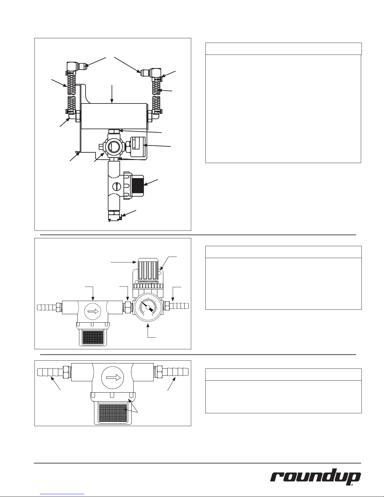
REPLACEMENT PARTS
! WARNING
18
MISUSE OF PRODUCTMAY CAUSE
PERSONALINJURY.READ ASME
INSTALATION/OPERATING INTRUCT
1/4
NPT
MADE IN USA IMI
R91G-24K-NLN
INLET 150 PSIG MAX
OUTLET 125 PSIGMAX
TEMP 125 F°MAX
Dual Water Pressure Regulator Kit - Part No. 7000235
To Steamer
2
4
1
To Steamer
10
9
Item Part No. Description Qty.
1 2080105 Elbow, Quick Disconnect - 1/4” 2
2 2030126 Tubing 1/4” I.D. PVC BRD. 24” Long 1
3 2030125 Tubing 1/4” I.D. PVC BRD. 12” Long 1
4 2040150 Elbow, Male - Nylon 2
1/4” Barb x 3/8” NPT
3
5 0503615 Bracket, Manifold Mtg. 1
6 2190129 Nipple 1/4” NPT x 1/4” NPT 1
7 2090127 Strainer - 1/4” FPT 1
8 2080118 Quick Disconnect - 1/8” NPT 1
9 2190113 Manifold 1
10 2110160 Clamp, Ear Med. 4
11
11 2040151 Nipple, HEx - 3/8” x 1/4” NPT Nylon 1
12 2170114 Gauge, Water Pressure 1
12
13 2170113 Regulator, Pressure 1
5
13
6
7
8
Water Supply
Single Water Pressure Regulator Kit - Part No. 7000314
4
3
1/4
NPT
6
30
40
20
200
kPa
300
100
10
50
0
400
0
60
psi
5
IMPORTANT: Two adjacent steamers can be fed with a
Dual Water Pressure Regulator.
1
2
Item Part No. Description Qty.
1 0503849 Bracket 1
2 2040130 Male Adapter, Barbed 1/4” 2
3 See Below for Strainer Parts Identification
4 2170113 Regulator, Pressure 1
5 2170114 Gauge, Water Pressure 1
6 2190129 Nipple 1/4” NPT x 1/4” NPT 1
7 2110104 Clamp, Worm (not shown) 2
1/4
NPT
5
NOTE: Item 1 is made
up of items 2 - 4
P/N 1010678 Rev. K 08/12
Item Part No. Description Qty.
1 7000333 Water Line Strainer Kit 1
2
2 2040130 Male Adapter, Barbed 1/4” 2
3 7000334 Replacement Screen and O-ring Kit 1
4 2110104 Clamp, Worm (not shown) 2
3
15
Page 16
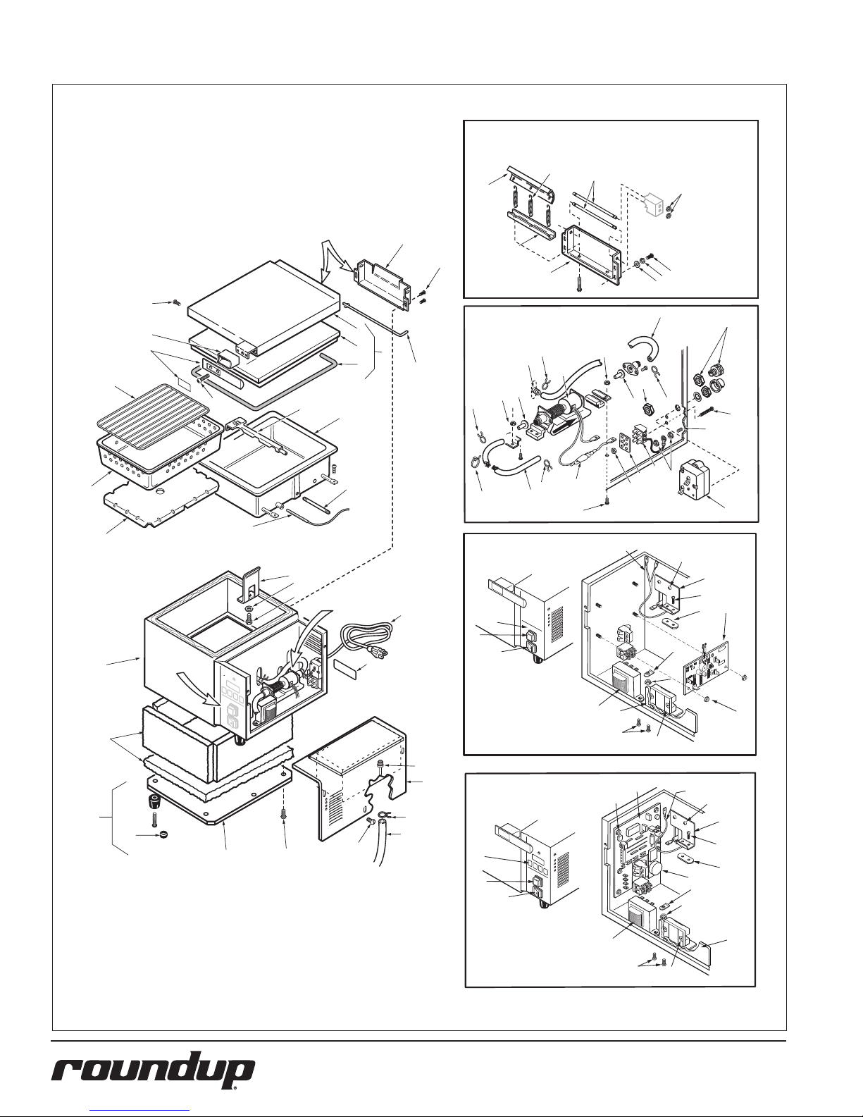
REPLACEMENT PARTS – DFW/DFWT-100/150
Inset A - Parts are used on DFWT-150 with
manufacturing number 9100128 only.
27
29
25
60
See Inset A
64
22
21
20
66
5
2
3
4
6
24
59
1
23
Inset B
67
28
26
67
7
70
61
62
63
33
53
44
57
70
58
67
57
68
69
42
70
19
7
72
33
32
67
71
18
Inset C
(Non-Timer)
8
17
63
61
See Inset B
9
Models DFW/DFWT-100
34
43
74
41
36
8
64
55
75
37
79
35
73
16
See Inset C
81
70
ANTUNES
T6
MADE IN USA
T5
R18
CR5
R8
SERIAL NO.
+
R11
T3
CR4
R5
CR2
+
+C5
R1
C1
R9
R16
VR1
PCB00-0234
C3T2
C6
R2
T4
R6
R15
R10
R4
U1
CR1
R13
C4
CR6
R14
R12
T1
15
13
12
14
39
54
59
40
74
51
31
77
33
64
64
16
Inset C
Timer Models
DFW/DFWT-150
34
35
36
8
38
74
64
55
75
79
56
73
70
39
59
40
54
P/N 1010678 Rev. K 08/12
Page 17
REPLACEMENT PARTS – DFW/DFWT-100/150 (continued)
Item Part No. Description Qty. Item Part No. Description Qty. Item Part No. Description Qty.
1 0011115 Top Cover Assy. (DFW) 1
(Incl. Nos. 2, 3 & 4)
0011154 Top Cover Assy. (DFWT) 1
(Incl. Nos. 2, 3 & 4)
0011162 Top Cover Assy. 1
(Mfg. # 9100128 only)
(Incl. Nos. 2, 3 & 4)
2 0020578 Shelf, Top Cover (DFW) 1
0020577 Shelf, Top Cover (DFWT) 1
0020453 Shelf, Top Cover 1
(Mfg. # 9100128 only)
3 0021065 Liner, Top Cover (DFW) 1
0021090 Liner, Top Cover (DFWT) 1
4 7000122 Gasket, Top Cover (DFW) 1
7000123 Gasket, Top Cover (DFWT) 1
5 0010145 Spray Tube Assy. (DFW) 1
0010146 Spray Tube Assy. (DFWT) 1
6 7000124 Steam Generator, 120V 1
(DFW Series) 1800 Watts
7000147 Steam Generator, 120V 1
(Mfg. # 9100102, 105)
7000125 Steam Generator, 230V 1
(DFW Series) 2800 Watts
7000126 Steam Generator, 120V 1
(DFWT Series) 1800 Watts
7000127 Steam Generator, 230V 1
(DFWT Series) 2800 Watts
7 7000448 Tube, Generator, 1
1/8” x 2-1/2”
(DFW/DFWT-100 Series)
8 4050210 Thermistor (Non-Timer 1
Models only)
4050209 Thermocouple (Timer 1
Models only)
9 0700451 Power Cord, 120 VAC, 1
14/3 5-20P
0700463 Power Cord, 120 VAC, 1
14/3 5-15P
0700453 Power Cord, 230 VAC, 1
CEE 7/7
0700437 Power Cord, 230 VAC, 1
IEC-309
10 7000139 Quick Disconnect, Male 1
12 218P145 Cover, Leg 1
13 210K230 Leg, 1” (Pack of 4) 1
14 0503069 Base Plate (DFW Series) 1
0503178 Base Plate (DFWT Series) 1
15 7000131 Insulation Kit (DFW) 1
7000132 Insulation Kit (DFWT) 1
16 0021055 Main Housing (DFW) 1
0021072 Main Housing (DFWT) 1
0021092 Main Housing 1
(Mfg. #9100128)
17 0503174 Retainer, Generator 2
18 0503177 Diffuser Pan (DFW) 1
0503182 Diffuser Pan (DFWT) 1
19 2130102 Perforated Pan (DFW) 1
2130103 Perforated Pan (DFWT) 1
20 0800106 Trivet (DFW) 1
0800109 Trivet (DFWT) 1
21 7000133 Handle Kit 1
(Incl. Nos. 22 & 66)
22 0020964 Cover, Handle Bracket 1
23 0800219 Hinge Pin, Top Cover 1
24 0501569 Hinge Base, Top Cover 1
25 0800280 Hinge Pin 1
(Mfg. #9100128 only)
26 0502719 Hinge Base 1
(Mfg. # 9100128 only)
27 0600125 Spring 3
(Mfg. # 9100128 only)
28 0020952 Hinge Beam 1
(Mfg. # 9100128 only)
29 0502722 Pivot Bracket 1
(Mfg. # 9100128 only)
31 0012546 Access Cover Assy. 1
32 7000214 Diode Assy. 1
33 7000849 Silicone Tube Kit 1
(Includes 2 tubes)
34 1000976 Label, Front Panel 1
(Non-Timer Models only)
1001036 Label, Front Panel 1
(Timer Models only)
35 4010166 Operate Switch 1
36 4010151 Rocker Switch, 120V 1
4010137 Rocker Switch, 230V 1
37 7000392 Control Board 1
(Non-Timer Models only)
38 7000317 Control Board 1
(Timer Models only)
39 7000319 Transformer 1
40 7000652 Relay, Solid State 1
41 7000135 Hi-Limit Thermostat 1
42 7000136 Terminal Block Kit 1
(Incl. No. 43)
43 100P967* Marking Label 1
44 7000137 Water Pump Kit, 24 VAC 1
(Incl. No. 32 & 33)
45 7000142 Outlet Tube Kit 1
(Incl. Nos. 46, 47 & 48)
46 204P114* Elbow, Female, 1/4” Tube 1
47 2000188 Outlet Tube 1
48 2040103 Connector, Male, 1
1/4” Tube
49 4040145 Solenoid, 24V 1
50 7000138 Quick Disconnect 1
Body & Plate Kit
51 0010159 Filter Assy., Water Tank 1
52 0010584 Inlet Hose Assy. 1
with Strainer
53 040K251 Strain Relief 1
54 0505699 Relay Heat Sink 1
55 0503333 Bracket, Temperature 1
Sensor
56 7000156 Audio Alarm Kit 1
57 7000170 Check Valve Kit, 1
Discharge & Intake
58 040P138* Locknut, Conduit, 1/2” 1
59 308P104* Screw, #8-32 x 3/8”, SS 1
60 211P127* Retaining Ring 1
61 325P109* Screw, Hex 1
62 325P154* Lockwasher 1
63 325P104* Washer, Flat 1
64 308P103* Screw, #8-32 x 1/4”, SS 1
65 308P164* Screw, #8-32 x 1”, SS 1
66 308P132* Screw, #8-32 x 3/4”, 1
Flat, SS
67 211P195* Hose Clamp 1
68 306P123* Screw, #6-32 x 7/8”, SS 1
69 308P124* Screw, #8-32 x 1/2”, 1
1-Way, SS
70 308P143* Nut, Hex, #8-32 KEPS 1
71 308P108* Screw, #8-32 x 3/4”, SS 1
72 406P107* Cable Tie 1
73 300P102* Nut, Tinnerman, U-type 1
74 306P130* Nut, Hex, #6-32 KEPS 1
75 306P103* Screw, #6-32 x 3/8”, SS 1
76 020P117* O-Ring 1
77 211P101* Hose Clamp, 3/8” Dia. 1
78 306P104* Screw, #6-32 x 1/4”, SS 1
79 301P106* Nut, Spotweld, #6-32 1
80 304P105* Nut, Hex, #4-40 KEPS 1
81 1000275 Label, Water & Waste 1
Connection
* Only available in packages of 10.
P/N 1010678 Rev. K 08/12
17
Page 18
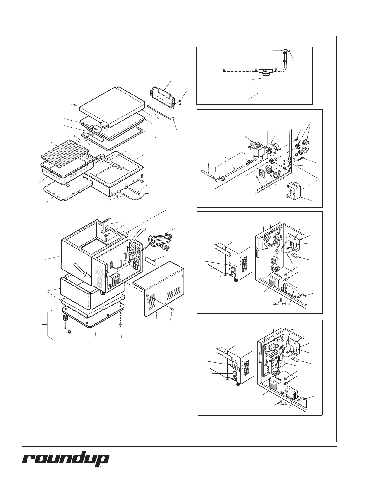
REPLACEMENT PARTS – DFW/DFWT-200/250
10
76
24
59
64
22
21
20
66
19
18
8
5
17
63
61
2
3
4
6
7
See Inset B
1
23
9
See Page 15
for Strainer Parts
Inset B
45
7
47
46
Inset C
(Non-Timer)
Models
DFW/DFWT-200
52
53
59
49
48
58
50
68
69
70
42
43
74
41
37
74
64
55
75
16
15
13
12
See Inset C
14
64
81
64
31
34
35
36
Inset C
Timer Models
DFW/DFWT-250
34
35
36
8
39
59
40
38
74
39
59
40
79
70
73
54
8
64
55
75
79
56
70
73
54
18
P/N 1010678 Rev. K 08/12
Page 19
REPLACEMENT PARTS – DFW/DFWT-200/250 (continued)
Item Part No. Description Qty.
1 0011115 Top Cover Assy. (DFW) 1
(Incl. Nos. 2, 3 & 4)
0011154 Top Cover Assy. (DFWT) 1
(Incl. Nos. 2, 3 & 4)
2 0020578 Shelf, Top Cover (DFW) 1
0020577 Shelf, Top Cover (DFWT) 1
3 0021065 Liner, Top Cover (DFW) 1
0021090 Liner, Top Cover (DFWT) 1
4 7000122 Gasket, Top Cover (DFW) 1
7000123 Gasket, Top Cover (DFWT) 1
5 0010145 Spray Tube Assy. (DFW) 1
0010146 Spray Tube Assy. (DFWT) 1
6 7000124 Steam Generator, 120V 1
(DFW Series) 1800 Watts
7000147 Steam Generator, 120V 1
(Mfg. # 9100112, 115)
7000125 Steam Generator, 230V 1
(DFW Series) 2800 Watts
7000126 Steam Generator, 120V 1
(DFWT Series) 1800 Watts
7000127 Steam Generator, 230V 1
(DFWT Series) 2800 Watts
7 7000447 Tube, Generator, 1
3-1/4" Lg.
8 4050210 Thermistor (Non-Timer 1
Models only)
4050209 Thermocouple (Timer 1
Models only)
9 0700451 Power Cord, 120 VAC, 1
14/3 5-20P
0700463 Power Cord, 120 VAC, 1
14/3 5-15P
0700453 Power Cord, 230 VAC, 1
CEE 7/7
0700437 Power Cord, 230 VAC, 1
IEC-309
10 7000139 Quick Disconnect, Male 1
12 218P145 Cover, Leg 1
13 210K230 Leg, 1" (Pack of 4) 1
14 0503069 Base Plate (DFW Series) 1
0503178 Base Plate (DFWT Series) 1
15 7000131 Insulation Kit (DFW) 1
7000132 Insulation Kit (DFWT) 1
Item Part No. Description Qty. Item Part No. Description Qty.
16 0021055 Main Housing (DFW) 1
0021072 Main Housing (DFWT) 1
17 0503174 Retainer, Generator 2
18 0503177 Diffuser Pan (DFW) 1
0503182 Diffuser Pan (DFWT) 1
19 2130102 Perforated Pan (DFW) 1
2130103 Perforated Pan (DFWT) 1
20 0800106 Trivet (DFW) 1
0800109 Trivet (DFWT) 1
21 7000133 Handle Kit 1
(Incl. Nos. 22 & 66)
22 0020964 Cover, Handle Bracket 1
23 0800219 Hinge Pin, Top Cover 1
24 0501569 Hinge Base, Top Cover 1
31 0505726 Access Cover Assy. 1
32 7000214 Diode Assy. 1
33 7000849 Silicone Tube Kit 1
(Includes 2 tubes)
34 1000976 Label, Front Panel 1
(Non-Timer Models only)
1001036 Label, Front Panel 1
(Timer Models only)
35 4010166 Operate Switch 1
36 4010151 Rocker Switch, 120V 1
4010137 Rocker Switch, 230V 1
37 7000392 Control Board 1
(Non-Timer Models only)
38 7000317 Control Board 1
(Timer Models only)
39 7000319 Transformer 1
40 7000652 Relay, Solid State 1
41 7000135 Hi-Limit Thermostat 1
42 7000136 Terminal Block Kit 1
(Incl. No. 43)
43 100P967* Marking Label 1
44 7000137 Water Pump Kit, 24 VAC 1
(Incl. No. 32 & 33)
45 7000142 Outlet Tube Kit 1
(Incl. Nos. 46, 47 & 48)
46 204P114* Elbow, Female, 1/4" Tube 1
47 2000188 Outlet Tube 1
48 2040103 Connector, Male, 1
1/4" Tube
49 4040145 Solenoid, 24V 1
50 7000138 Quick Disconnect 1
Body & Plate Kit
51 0010159 Filter Assy., Water Tank 1
52 0010584 Inlet Hose Assy. 1
with Strainer
53 040K251 Strain Relief 1
54 0505699 Relay Heat Sink 1
55 0503333 Bracket, Temperature 1
Sensor
56 7000156 Audio Alarm Kit 1
57 7000170 Check Valve Kit, 1
Discharge & Intake
58 040P138* Locknut, Conduit, 1/2" 1
59 308P104* Screw, #8-32 x 3/8", SS 1
60 211P127* Retaining Ring 1
61 325P109* Screw, Hex 1
62 325P154* Lockwasher 1
63 325P104* Washer, Flat 1
64 308P103* Screw, #8-32 x 1/4", SS 1
65 308P164* Screw, #8-32 x 1", SS 1
66 308P132* Screw, #8-32 x 3/4", 1
Flat, SS
67 211P103* Hose Clamp, 1/2" Dia. 1
68 306P123* Screw, #6-32 x 7/8", SS 1
69 308P124* Screw, #8-32 x 1/2", 1
1-Way, SS
70 308P143* Nut, Hex, #8-32 KEPS 1
71 308P108* Screw, #8-32 x 3/4", SS 1
72 406P107* Cable Tie 1
73 300P102* Nut, Tinnerman, U-type 1
74 306P130* Nut, Hex, #6-32 KEPS 1
75 306P103* Screw, #6-32 x 3/8", SS 1
76 020P117* O-Ring 1
77 211P101* Hose Clamp, 3/8" Dia. 1
78 306P104* Screw, #6-32 x 1/4", SS 1
79 301P106* Nut, Spotweld, #6-32 1
80 304P105* Nut, Hex, #4-40 KEPS 1
81 1000275 Label, Water & Waste 1
Connection
* Only available in packages of 10.
P/N 1010678 Rev. K 08/12
19
Page 20
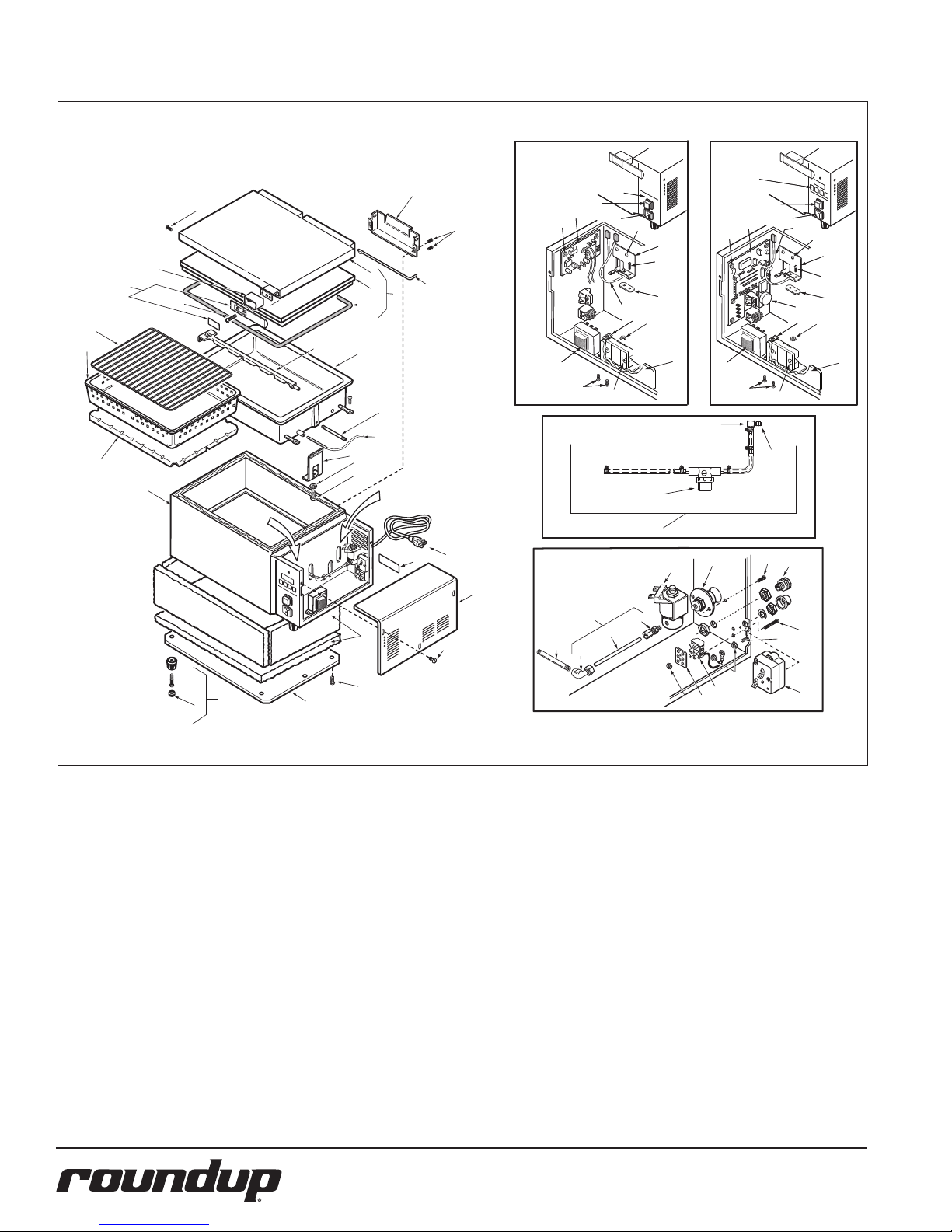
REPLACEMENT PARTS – DFWF-250 ONLY
Inset A
Non-Timer Model
Mfg. No. 9100147
24
B
A
22
21
F
20
19
18
16
See
Inset A
5
17
6
E
D
11
2
3
4
7
8
See Inset B
23
1
9 (See
Page 5)
46
10
B
K
39
7
35a
36
38a
37
8
A
40
See Page 25
for Strainer Parts
29
31
30
B
44
M
P
L
I
41
33
32
Inset B
Timer Model
only
35
36
37
38
K
43
39
A
8
B
44
M
P
45
L
I
43
40
42
N
A
34
25
G
H
14
15
12
B
K
I
27
28
26
20
P/N 1010678 Rev. K 08/12
Page 21
REPLACEMENT PARTS – DFWF-250 ONLY (continued)
Item Part No. Description Qty.
1 0011165 Top Cover Assy. 1
(Incl. Items 2, 3, & 4)
2 0020769 Top Cover Shell 1
3 0021094 Top Cover Liner 1
4 7000140 Top Cover Gasket Kit 1
5 0010147 Spray Tube Assy. 1
6 7000220 Generator, 230 VAC 1
7000221 Generator, 208 VAC 1
7 7000447 Steam Generator Tube 1
8 4050209 Thermocouple 1
(Timer Models Only)
8a 4050210 Probe Thermistor 1
(Non-Timer Models)
(Mfg. No. 9100417)
9 0700452 Power Cord (6-20P) 1
0700453 Power Cord (CEE 7/7) 1
10 0503102 Access Cover 1
11 7000141 Insulation Kit 1
12 0503103 Base Plate 1
14 210K230 Leg, 1” (Pack of 4) 1
15 218P145* Cover, Leg 1
16 0021095 Main Housing 1
17 0503186 Generator Retainer 2
18 0503187 Diffuser Pan 1
19 2130171 Pan, Full Size 1
20 0800113 Trivet 1
21 7000133 Handle Kit (Incl. #22) 1
22 0020964 Handle Bracket Cover 1
Item Part No. Description Qty.
23 0800219 Top Cover Hinge Pin 2
24 0501569 Cover Hinge Base 2
25 040K251 Strain Relief 1
26 7000135 Hi-Limit Thermostat 1
27 7000136 Terminal Block Kit 1
(Incl. Item 28)
28 100P967* Marking Label 1
29 7000142 Outlet Tube Kit 1
(Incl. #30, 31, & 32)
30 204P114* Female Elbow 1/4” 1
31 2000188 Outlet Tube 1
32 2040103 Male Connector, 1/4” 1
33 4040145 Solenoid 24 VAC 1
34 7000138 Quick Disconnect 1
Body & Plate Kit
35 1001036 Front Panel Label 1
(Timer Models Only)
35a 1000976 Front Panel Label 1
(Non-Timer Models)
(Mfg. No. 9100147)
36 4010166 Operate Switch 1
37 4010137 Power Switch 1
38 7000317 Control Board 1
(Timer Models Only)
38a 7000392 Control Board 1
(Non-Timer Models)
(Mfg. No. 9100147)
39 7000319 Transformer 1
40 7000652 Solid State Relay 1
Item Part No. Description Qty.
41 0010584 Inlet House Assy. 1
with Strainer
42 7000139 Quick Disconnect Kit 1
43 0505699 Heat Sink 1
44 0503333 Temp. Sensor Bracket 1
45 7000156 Audio Alarm Kit 1
46 4050210 Probe, Thermistor 1
(Mfg. No. 9100147)
A 308P104* Screw, #8-32 x 3/8” 1
B 308P103* Screw, #8-32 x 1/4” 1
C 308P164* Screw, #8-32 x 1” 1
D 325P109* Hex Screw, 1
#1/4” x 20 x 1/2”
E 325P104* Flat Washer 1
F 308P132* #8-32 x 3/4” Flat 1
G 306P123* Screw, #6-32 x 7/8” 1
H 308P124* Screw, #8-32 x 1/2”
1 Way 1
I 308P143* Hex Nut, #8-32, “KEPS” 1
J 306P101* Hex Nut, #6-32 - SS 1
K 306P130* Hex Nut, #6-32 “KEPS” 1
L 300P102* “U” Type Tinnerman 1
M 306P103* Screw, #6-32 x 3/8” 1
N 020P117* Quick Disconnect O-Ring 1
O 306P104* Screw, #6-32 x 1/4” 1
P 301P106* Spotweld Nut, #6-32 1
* Items are available only in packages
of ten (10) each.
P/N 1010678 Rev. K 08/12
21
Page 22
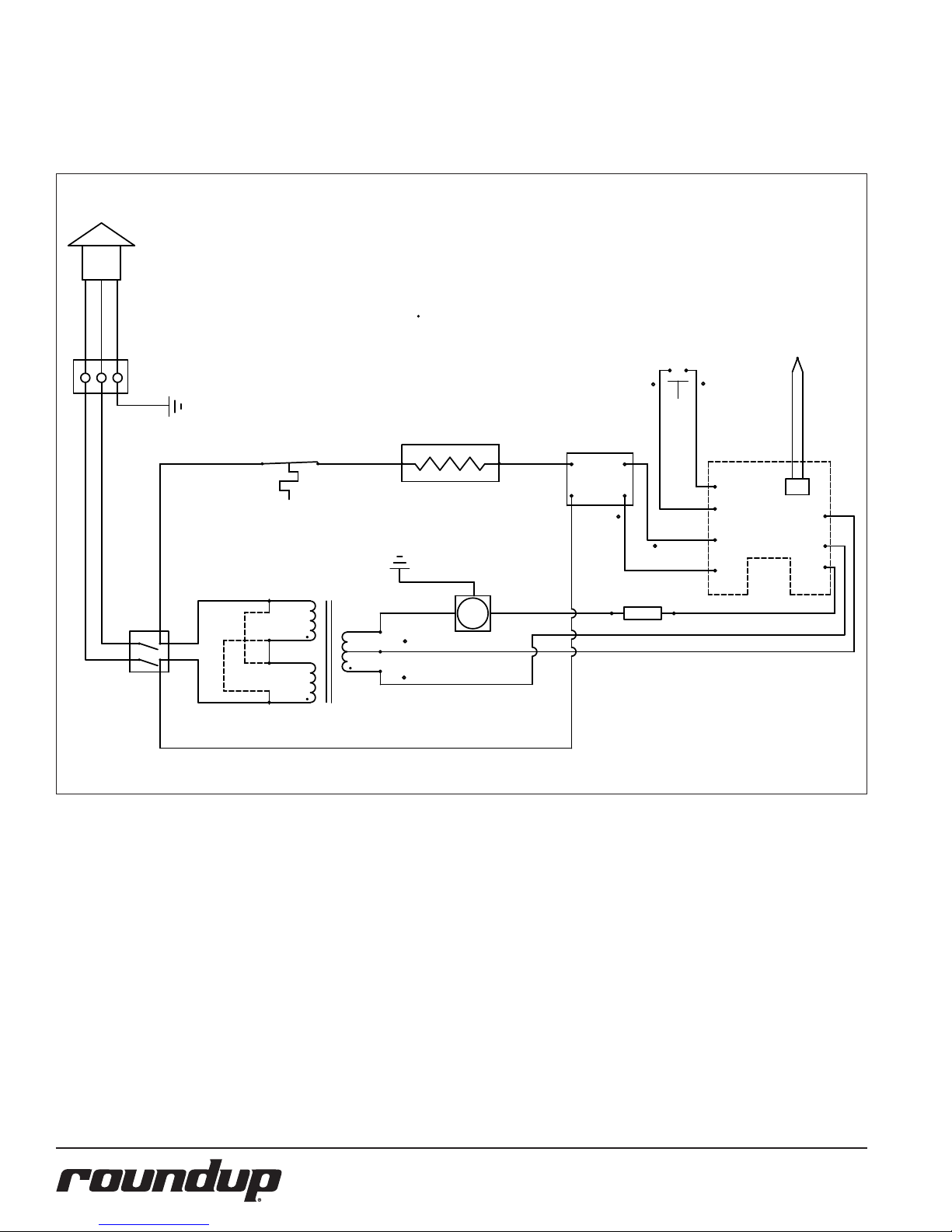
WIRING DIAGRAM
Timer Models Only - Except DFWF-250 units with Mfg. No. 9100147
POWER
CORD
DFW/DFWT/DFWF-150/250 Only
WIRING DIAGRAM
NOTE: ALL WIRES TO BE 14 GA. AWM-105°C
UNLESS OTHERWISE SPECIFIED.
# 18 GA. AWM-105°C
BLK/BRN
BLK
GRN
WHT/BLU
WHT
POWER
SWITCH
GRN-YEL
TERMINAL
BLOCK
GRN
21
54
GND
WHT
WHT
BLK
HI-LIMIT
THERMOSTAT
#
120V 230V
#
BLK
5
4
2
1
TRANSFORMER
WHT
(PUMP ONLY)
10
GND
8
6
22 GA. AWM-105°C
HEATER
BLK
SOLENOID
OR
PUMP
#
ORG
BRN
BRN
S.S. RELAY
213+
4-
YEL
(PUMP ONLY)
MOMENTARY
BLU
RED
DIODE
SWITCH
BLU
T2
T1
T3
T7
#
CONTROL
BLK
THERMOCOUPLE
T4
BOARD
T5
T6
22
P/N 1010678 Rev. K 08/12
Page 23
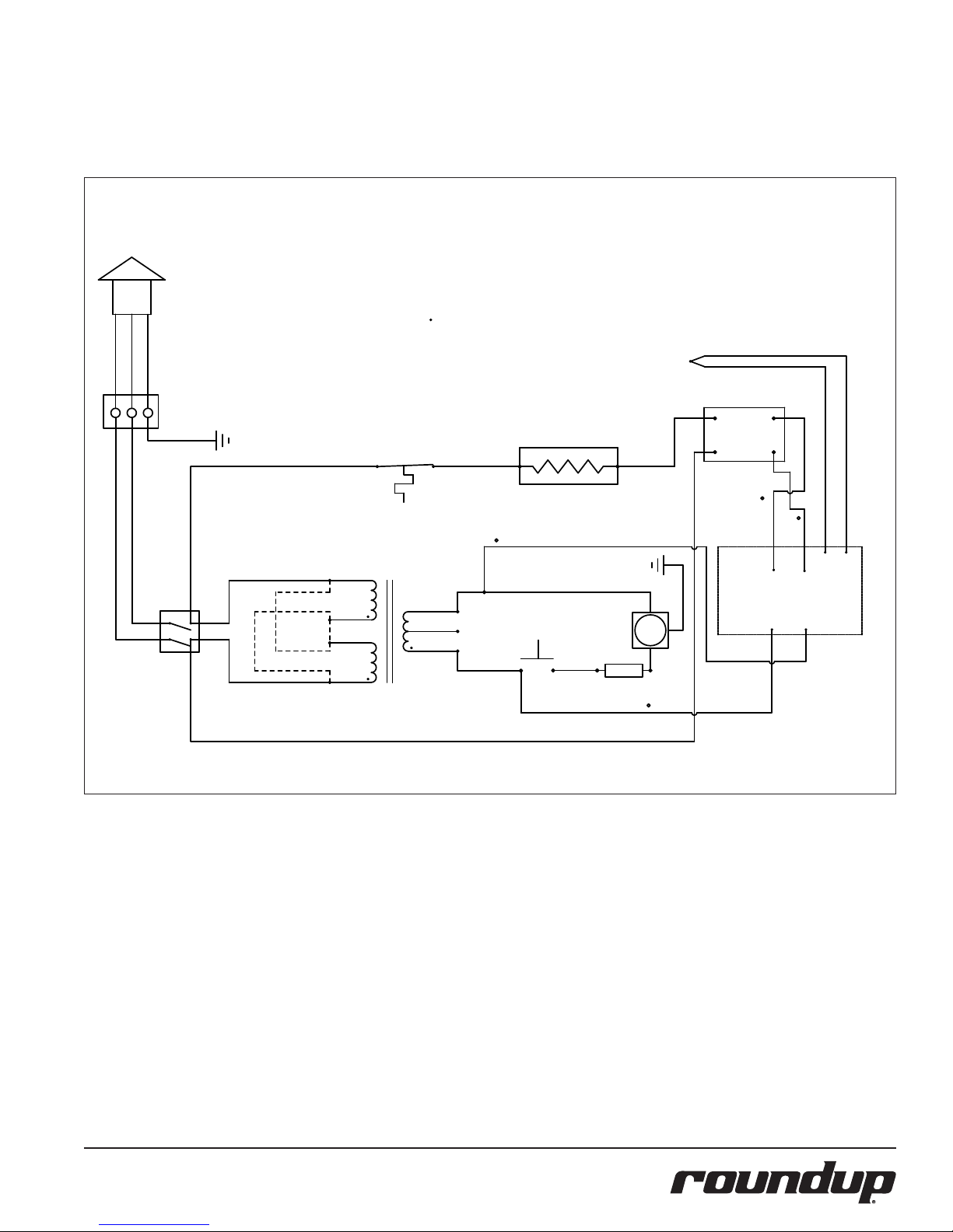
WIRING DIAGRAM (continued)
DFW/DFWT-100/200 and DFWF-250 Models with Mfg. No. 9100147 Only.
POWER
CORD
BLK/BRN
BLK
WHT/BLU
WHT
POWER
SWITCH
GRN
GRN-YEL
TERMINAL
BLOCK
GRN
GND
WHT
#
21
54
#
BLK
120V 230V
NOTE: ALL WIRES TO BE 14 GA. AWM-105°C
WHT
5
4
2
1
Timer Models Only.
WIRING DIAGRAM
UNLESS OTHERWISE SPECIFIED.
# 18 GA. AWM-105°C
22 GA. AWM-105°C
BRN
ORG
HEATER
(PUMP ONLY)
SOLENOID
#
BLK
HI-LIMIT
THERMOSTAT
TRANSFORMER
WHT BLK
#
10
8
MOMENTARY
SWITCH
6
#
BLK
GND
OR
PUMP
DIODE
(PUMP ONLY)
BRN
THERMISTOR
S.S. RELAY
2 3+
1 4-
RED
T5
T2
YEL
T3 T4
T6
T1
TEMP
CONTROL
P/N 1010678 Rev. K 08/12
BLK
23
Page 24
LIMITED WARRANTY
Equipment manufactured by Roundup Food Equipment Division of A.J. Antunes & Co. has been constructed of the finest materials available and manufactured to high quality standards. These units are warranted to be free from electrical and mechanical
defects for a period of one (1) year from date of purchase under normal use and service, and when installed in accordance with
manufacturer’s recommendations. To insure continued operation of the units, follow the maintenance procedures outlined in the
Owner’s Manual. During the first 12 months, electro-mechanical parts, non-overtime labor, and travel expenses up to 2 hours (100
miles/160 km), round trip from the nearest Authorized Service Center are covered.
1. This warranty does not cover cost of installation, defects caused by improper storage or handling prior to placing of the Equipment.
This warranty does not cover overtime charges or work done by unauthorized service agencies or personnel. This warranty does
not cover normal maintenance, calibration, or regular adjustments as specified in operating and maintenance instructions of this
manual, and/or labor involved in moving adjacent objects to gain access to the equipment. This warranty does not cover consumable/wear items. This warranty does not cover damage to the Load Cell or Load Cell Assembly due to abuse, misuse, dropping of
unit/shock loads or exceeding maximum weight capacity (4 lbs). This warranty does not cover water contamination problems such
as foreign material in water lines or inside solenoid valves. It does not cover water pressure problems or failures resulting from
improper/incorrect voltage supply. This warranty does not cover Travel Time & Mileage in excess of 2 hours (100 miles/160 km) round
trip from the nearest authorized service agency.
2. Roundup reserves the right to make changes in design or add any improvements on any product. The right is always reserved to
modify equipment because of factors beyond our control and government regulations. Changes to update equipment do not constitute a warranty charge.
3.
If shipment is damaged in transit, the purchaser should make a claim directly upon the carrier. Careful inspection should be made of the
shipment as soon as it arrives and visible damage should be noted upon the carrier’s receipt. Damage should be reported to the carrier.
This damage is not covered under this warranty.
4. Warranty charges do not include freight or foreign, excise, municipal or other sales or use taxes. All such freight and taxes are the
responsibility of the purchaser.
5. THIS WARRANTY IS EXCLUSIVE AND IS IN LIEU OF ALL OTHER WARRANTIES, EXPRESSED OR IMPLIED, INCLUDING ANY IMPLIED
WARRANTY OR MERCHANTABILITY OR FITNESS FOR A PARTICULAR PURPOSE, EACH OF WHICH IS HEREBY EXPRESSLY DISCLAIMED. THE REMEDIES DESCRIBED ABOVE ARE EXCLUSIVE AND IN NO EVENT SHALL ROUNDUP BE LIABLE FOR SPECIAL CONSEQUENTIAL OR INCIDENTAL DAMAGES FOR THE BREACH OR DELAY IN PERFORMANCE OF THIS WARRANTY.
 Loading...