

Page 1
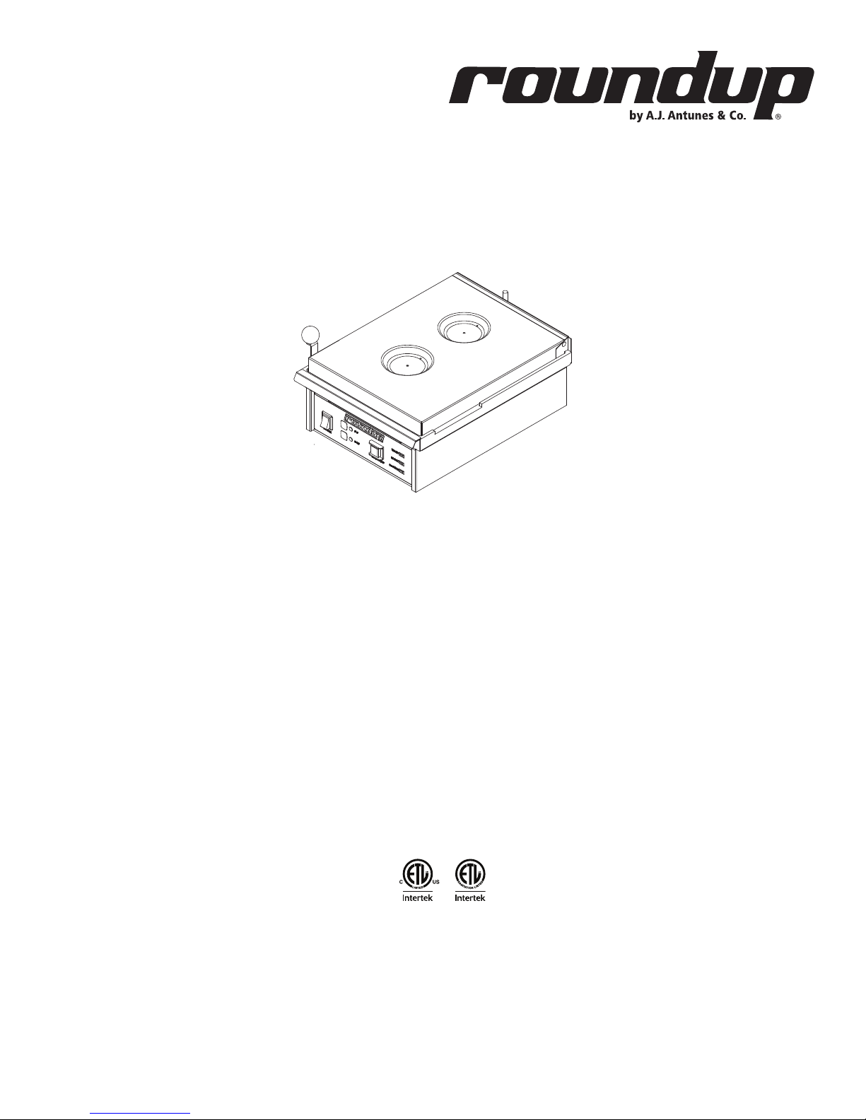
Egg Station
Model ES-600, ES-602,
ES-604, & ES-1200
owner’s manual
Manufacturing Numbers:
9300530, 9300532, 9300534, 9300571, 9300574,
9300575, 9300577, 9300593, 9300621
www.ajantunes.com P/N 1010883 Rev L 12/15
Page 2

CONTENTS
General 2
Warranty Information 2
Service/Technical
Assistance 2
Important Safety
Information 3
Warnings 3
Specications 4
Installation 5
Unpacking 5
Equipment Setup 5
Operating
Instructions 6
Preparing Unit 6
Egg Cooking Procedure 6
Bacon Timer*
(All units EXCEPT Mfg. No. 9300534) 7
Maintenance 8
Daily Cleaning 8
Checking Cycle Times (Monthly)
(All units EXCEPT Mfg. No. 9300534) 8
Checking Cycle Times (Monthly)
(Mfg. No. 9300534 ONLY) 8
Checking Grill Platen Temperature 9
Troubleshooting 10
Control Board LEDs 11
Green LED Blink Codes 11
Wiring Diagram 12
Replacement Parts 13
IMPORTANT
A.J. Antunes & Co. reserves the right to
change specications and product de-
sign without notice. Such revisions do not
entitle the buyer to corresponding changes,
improvements, additions or replacements
for previously purchased equipment.
IMPORTANT
Keep these instructions for future refer-
ence. If the unit changes ownership, be sure
this manual accompanies the equipment.
GENERAL
This product cooks/steams eggs (refrigerated) in approximately 150 seconds and
reheats sliced meat for sandwiches. Eggs
within the Egg Rings are cooked with a
combination of heat and steam. With the
cover closed, water is poured into a trough
on the cover and drips onto a hot Platen,
producing steam and cooking the eggs. The
unit is equipped with audio/visual signals
for operation.
This manual provides the safety, installation, and operating procedures for the Egg
Station. We recommend that all information
contained in this manual be read prior to
installing and operating the unit.
Your Egg Station is manufactured from
the nest materials available, assembled
to Roundup’s strict quality standards, and
tested at the factory to ensure dependable
trouble-free operation.
WARRANTY
INFORMATION
Please read the full text of the Limited
Warranty printed on the back cover of this
manual.
If the unit arrives damaged, contact the
carrier immediately and le a damage claim
with them. Save all packing materials when
ling a claim. Freight damage claims are
the responsibility of the purchaser and not
covered under warranty.
The warranty does not extend to:
y Damages caused in shipment or
damage as result of improper use.
y Installation of electrical service.
y Installation, calibration,
or adjustment.
y Normal maintenance
outlined in this manual.
y Consumable parts such as Egg
Rings, gaskets, rubber feet,
labels, O-rings, light bulbs, etc.
y Malfunction resulting from
improper service or maintenance.
y Damage caused by improper
installation, abuse, or
careless handling.
y Damage from moisture getting
into electrical components.
y Damage from tampering with,
removal of, or changing any
preset control or safety device.
y Damage caused by parts or
components not provided
by A.J. Antunes & Co.
SERVICE/TECHNICAL
ASSISTANCE
If you experience any problems with the
installation or operation of your system,
contact A.J. Antunes & Co. at 1-630-7841000, or toll free in the United States at
1-800-253-2991.
Fill in the information in the next column and have it handy when calling for
assistance. The serial number is on the
specication plate located on the system.
Purchased From
Date of Purchase
Model Number
Serial Number
Mfg. Number
Use only genuine Roundup replacement
parts in this unit. Use of replacement parts
other than those supplied by the manufacturer will void the warranty. Your Authorized
Service Agency has been factory trained
and has a complete supply of parts for this
unit.
Visit www.ajantunes.com or contact the
factory at 1-630-784-1000 to locate your
nearest Authorized Service Agency. Refer
to the service agency directory packaged
with your manual and ll in the information
below.
Authorized Service Agency
Name
Phone Number
Address
P/N 1010883 REV. L 12/152
Page 3

IMPORTANT SAFETY
INFORMATION
Use the following guidelines for safe operation of the unit.
y Read all instructions before
using equipment.
y For your safety, the equipment is
furnished with a properly grounded
cord connector. Do not attempt to
defeat the grounded connector.
y Install or locate the equipment only
for its intended use as described in
this manual. Do not use corrosive
chemicals in this equipment.
y Do not operate this equipment if
it has a damaged cord or plug, if
it is not working properly, or if it
has been damaged or dropped.
y This equipment should be serviced
by qualied personnel only. Contact
your nearest Authorized Service
Agency for adjustment or repair.
y Do not block or cover any
openings on the unit.
y Do not immerse cord or plug in water.
y Keep cord away from heated surfaces.
y Do not allow cord to hang over
edge of table or counter.
The following warnings and cautions appear
throughout this manual and should be carefully observed.
y Turn the power o, unplug the
power cord, and allow unit to cool
down before performing any service
or maintenance on the unit.
y The equipment should be grounded
according to local electrical codes to
prevent the possibility of electrical
shock. It requires a grounded
receptacle with separate electrical
lines, protected by fuses or circuit
breaker of the proper rating.
y All electrical connections must be in
accordance with local electrical codes
and any other applicable codes.
y Do not clean this appliance
with a water jet.
WARNINGS
Be advised of the following warnings when
operating and performing maintenance on
this unit.
y If the supply cord is damaged,
it must be replaced by the
manufacturer or its service agent
or a similarly qualied person
in order to avoid a hazard.
y Do not modify the power supply
cord plug. If it does not t the
outlet, have a proper outlet
installed by a qualied electrician.
y Do not use an extension
cord with this appliance.
y Electrical ground is required
on this appliance.
y Check with a qualied electrician
if you are unsure if the appliance
is properly grounded.
y If a chemical cleaner is used,
be sure it is safe to use on cast
aluminum. Observe all precautions
and warnings on product label.
y Inspection, testing, and
repair of electrical equipment
should only be performed by
qualied service personnel.
y This equipment is to be installed to
comply with the basic plumbing code
of the Building Ocials and Code
Administrators, Inc. (BOCA) and the
Food Service Sanitation Manual of the
Food and Drug Administration (FDA).
y Do not use abrasive materials. The
use of these may cause damage
to the stainless steel nish.
y Chlorides or phosphates in cleaning
agents (e.g. bleach, sanitizers,
degreasers or detergents) could cause
permanent damage to stainless steel
equipment. The damage is usually in
the form of discoloration, dulling of
metal surface nish, pits, voids, holes,
or cracks. This damage is permanent
and not covered by warranty.
The following tips are recommended
for maintenance of your stainless steel
equipment:
y Always use soft, damp cloth for
cleaning, rinse with clear water and
wipe dry. When required, always rub
in direction of metal polish lines.
y Routine cleaning should be
done daily with soap, ammonia
detergent, and water.
y Stains and spots should be sponged
using a vinegar solution.
y Finger marks and smears should be
rubbed o using soap and water.
y Hard water spots should be
removed using a vinegar solution.
P/N 1010883 REV. L 12/15 3
Page 4
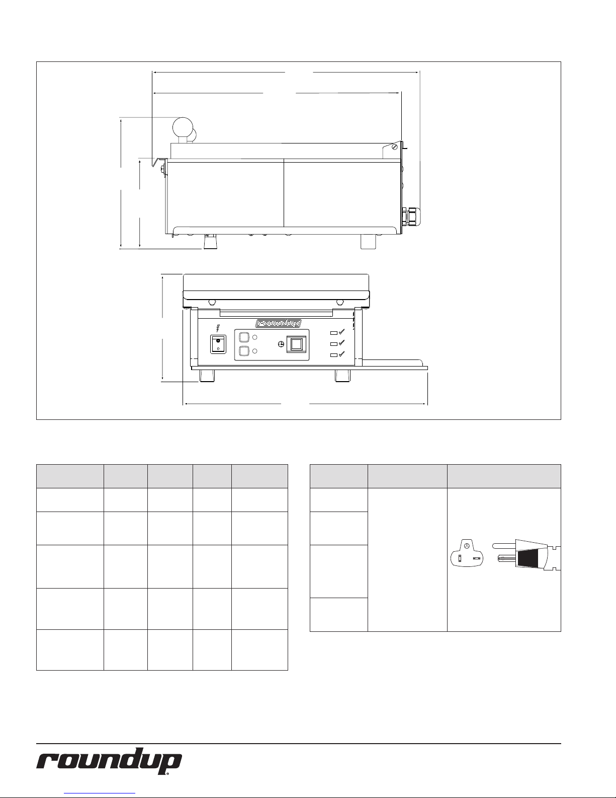
SPECIFICATIONS
8 15/16"
(227 mm)
6 3/16"
(157 mm)
18 3/16"
(462 mm)
16 15/16"
(430 mm)
Model &
Mfg. No.
ES-600
9300530
ES-602
9300571
9300577
ES-604
9300574
9300575
ES-1200
9300532
9300534
ES-604
9300593
9300621
7 9/32"
(185 mm)
POWER
1
2
Volts Watts Amp Hertz
208 2400 11.5 50/60
208 2400 11.5 50/60
208 2400 11.5 50/60
208 2400 11.5 50/60
208/220
- 240~
2400 /
3150
11.5 /
10.9
- 13.1
50/60
2'-00"
2'-30"
START/STOP
16 5/8"
(422 mm)
READY
BACON
COOKING
Model & Mfg.
No.
Description Conguration
ES-600
9300530
ES-602
9300571
9300577
ES-604
9300574
9300575
9300593
6-20P, 20 Amp., 250
VAC.,
Non-Locking
(Assembly Only)
9300621
ES-1200
9300532
9300534
Shipping Weight
y ES-600: 48 lbs. (21.7 kg)
y ES-602, ES-604, & ES-1200: 50 lbs. (22.6 kg)
Net Weight
y ES-600: 41 lbs. (18.6 kg)
y ES-602, ES-604, & ES-1200: 43 lbs. (19.5 kg)
P/N 1010883 REV. L 12/154
Page 5

INSTALLATION
Unpacking
1. Remove unit and all packing materi-
als from
shipping carton.
NOTE: If any parts are missing or dam-
aged, contact A.J. Antunes & Co.
Technical Service IMMEDIATELY
at 1-877-392-7854 (Toll free
in the U.S. and Canada) or
630-784-1000.)
2. Remove information packet.
3. Remove all packing materials and
protective coverings from the unit.
4. Wipe all surfaces of the unit with a
hot damp cloth.
NOTE: Do NOT use a dripping wet cloth.
Wring it out before use.
5. Clean the Egg Rings, Egg Rack, Top
Cover, and Service Pans in hot, soapy
water. Rinse in clear water and allow
to air dry.
6. Reassemble all parts to unit.
Equipment Setup
When placing the unit into service, pay attention to the following guidelines:
y Make sure power is o and the
unit is at room temperature.
y Do NOT block or cover any
openings on the unit.
y Do NOT immerse cord
or plug in water.
y Keep cord away from heated surfaces.
y Do NOT allow cord to hang over
edge of table or counter.
y Place the unit on a sturdy, level
table or other work surface.
y Ensure that the line voltage
corresponds to the stated voltage on
the unit’s specication label. If unsure,
have an electrician conrm correct
line voltage before connecting unit.
y Place the unit on a sturdy,
level surface.
y Make sure the unit is also level
so that water does not run from
one side to the other. Adjust the
legs as needed to level the unit.
CAUTION
All electrical connections must be in
accordance with local electrical codes
and any other applicable codes.
WARNING
y ELECTRICAL SHOCK HAZARD.
Failure to follow the instructions
in this manual could result
in serious injury or death.
y Electrical ground is required
on this appliance.
y Do NOT modify the power supply
cord plug. If it does not t the
outlet, have a proper outlet
installed by a qualied electrician.
y Do NOT use an extension
cord with this unit.
y The unit should be grounded
according to local electrical
codes to prevent the possibility
of electrical shock. It requires
a grounded receptacle with
separate electrical lines,
protected by fuses or circuit
breaker of the proper rating.
y Check with a qualied electrician
if you are unsure if the appliance
is properly grounded.
IMPORTANT
When installing the unit, use a leveler to
ensure that the table/cart is level and that
the unit is level when placed. If necessary,
adjust the two front bottom legs of the unit
to level it. Failure to level the table and/or
unit may result in unevenly cooked product.
P/N 1010883 REV. L 12/15 5
Page 6
OPERATING
INSTRUCTIONS
Preparing Unit
1. Turn the unit on and allow it to warm
up for approximately 20–30 minutes.
NOTE: During warm up, the Ready
Indicator Light ashes. The
Ready Indicator Light stays on
once the unit reaches operating
temperature.
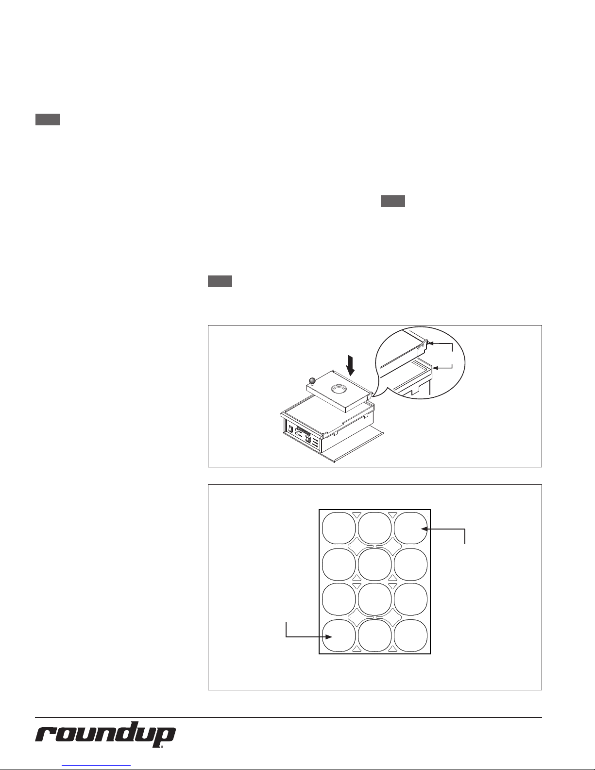
2. If necessary, install the Top Cover
according to Figure 1.
3. Install the Egg Rack by holding it
vertically and sliding the pins of the
Egg Rack into the slots on the back
of the Top Cover.
4. Install the Egg Rings into the Egg
Rack (Figure 3). Make sure the Egg
Rings are seated at on the Platen
surface.
5. Ensure that the Egg Rack and Top
Cover are in the down position while
the cooker warms up.
6. Add melted butter (or equivalent) to
one Service Pan (if desired) and slide
the Service Pan into the tray on right
side of unit.
7. Slide the second Service Pan into the
tray for use for collecting scraps and
unused product (if desired).
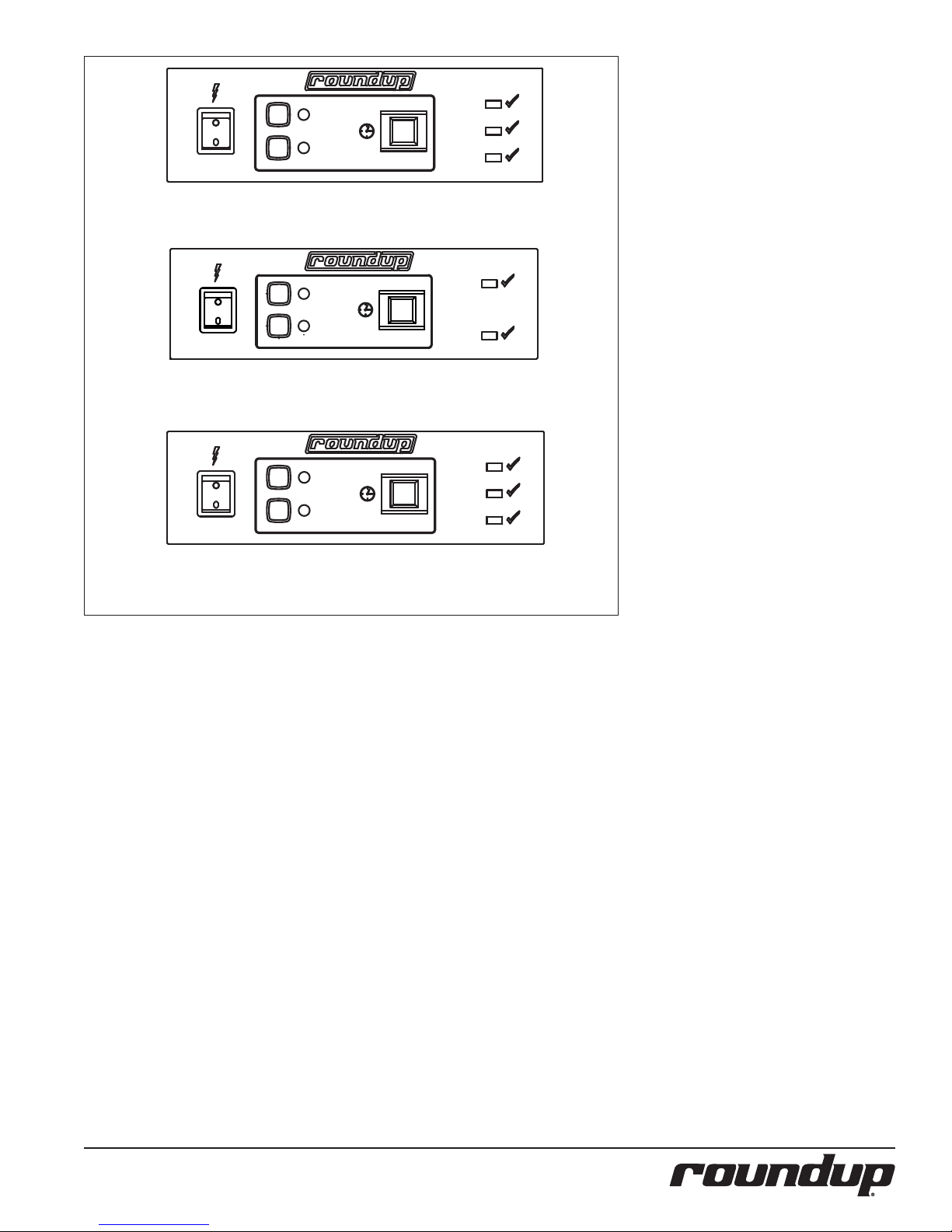
6. Select the desired cooking cycle
(Figure 3).
All units Except Mfg. No. 9300534:
Use a two-minute cycle for room
temperature eggs or the two-anda-half-minute cycle for refrigerated
eggs (Figure 3 top).
No. 9300534 Only:
Select 6 for six eggs or 12 for twelve
eggs (Figure 3 bottom)
7. All units EXCEPT Mfg. No. 9300534:
If desired, place sliced meat
(Canadian bacon, ham, etc.) on the
front part of the Platen when Bacon
Indicator Light begins to ash and
the audio signal sounds (see Bacon
Timer in the Operation section of this
manual).
8. Press the Start/STOP button to begin
the cooking cycle.
NOTE: The Cooking Indicator Light will
light when the Start/Stop button
is pressed and released.
9. At the end of the cycle, when the
Cooking Indicator Light turns o,
press the Start/Stop button to turn
o the audio signal.
10. All units EXCEPT Mfg. No. 9300534:
Remove the meat from the Platen
surface (see the Bacon Timer section
of this manual).
11. Open the cover and raise the Egg
Rack about 1 inch (26 mm), then
drop the rack to loosen the eggs.
12. Raise the Egg Rack completely
o the eggs and use a spatula to
remove the eggs.
NOTE: Refer to Figure 2. Remove eggs
starting with the rst egg added
and nish with the last egg
added. This ensures even cooking
for all eggs.
13. Scrape and waste from Platen grill
surface into the Service Pan.
14. Lower the Egg Rack and Cover. The
unit is ready for further cooking.
Slide notch
over tab
Egg Cooking Procedure
Read these instructions prior to cooking
eggs.
1. Make sure the grill is clean and
free of all extra butter, oils, or egg
product.
2. Raise the Top Cover and brush the
Egg Rings and Grill surface with
melted butter or equivalent.
3. Crack the eggs into the Egg Rings
from right to left as shown in Figure
2, starting at the row closest to the
front of the unit.
4. Break the egg yolks if desired and
close the Top Cover.
5. Fill the troughs on the Top Cover
with warm water until they are completely full. This is very important to
get a completely cooked egg with a
jelled yolk. Using less water results in
under-cooked eggs.
The Top Cover Shown is for
Reference only. Dierent
units use dierent covers.
Figure 1. Installing Top Cover
To ensure proper cooking, place eggs into rings in numerical order from 1 to 12 as shown below.
1 0
FIFO (First in,
rst out) The rst
egg in should
always be the
rst egg out
7
4
1
NOTE - The size and number of Egg Rings may vary based on the type of unit installed.
1 1 1 2
8 9
5 6
2 3
Front of Unit
LILO (Last in, last
out) The last egg
in should always
be the last egg
out
Figure 2. Sample Egg Cooking Procedure
P/N 1010883 REV. L 12/156
Page 7
START/STOP
POWER
2'-00"
2'-30"
READY
COOKING
BACON
1
2
FOR MFG. NO. 9300530, 532, 571, 574, 575, & 593:
NOTE THE FOLLOWING ARE FACTORY PRESET COOKING TIMES.
TIME 1 BUTTON: 2 MINUTE COOKING TIME.
TIME 2 BUTTON: 2 MINUTES AND 30 SECONDS COOKING TIME.
2'-45"
6
2'-30"
12
POWER
NOTE THE FOLLOWING ARE FACTORY PRESET COOKING TIMES.
TIME 6 BUTTON 6 EGGS: 2 MINUTES 45 SECONDS COOKING TIME.
TIME 12 BUTTON 12 EGGS: 2 MINUTES 30 SECONDS COOKING TIME.
POWER
NOTE THE FOLLOWING ARE FACTORY PRESET COOKING TIMES.
FOR MFG. N O. 9300534 ONLY:
2'-00"
1
3'-00"
2
FOR MFG. N O. 9300621 ONLY:
TIME 1 BUTTON: 2 MINUTE COOKING TIME.
TIME 2 BUTTON: 3 MINUTE TIME.
START/STOP
START/STOP
COOKING
COOKING
Figure 3. Time Selector Switch
READY
READY
BACON
Bacon Timer*
(All units EXCEPT Mfg. No.
9300534)
If, during the standby mode, the Bacon
Indicator Light is not lit, it means that the
Bacon Timer is disabled. To enable the
Bacon Timer, with the unit turned on, press
the TIME 1 and TIME 2 buttons simultaneously for 3 or more seconds. The Bacon
Indicator Light will turn on. The Bacon
Timer is now enabled.
To disable the Bacon Timer, press the TIME
1 and TIME 2 buttons simultaneously for
3 or more seconds. The Bacon Indicator
Light will turn o. The Bacon Timer is now
disabled.
Using the Bacon Timer
If the Bacon Timer is enabled, an audio
signal will sound for a few seconds and the
Bacon Indicator Light will begin to ash
30 seconds before the end of the cooking
cycle.
During this time, the product should be
placed on the front part of the grill so
that it will heat for 30 seconds. The Bacon
Indicator Light will continue to ash until
the end of the cooking cycle.
* ES-600 units are designed to operate with
the Bacon Timer enabled. ES-602, ES-604
and ES-1200 units are designed to operate
with the Bacon Timer disabled.
P/N 1010883 REV. L 12/15 7
Page 8
MAINTENANCE
WARNING
Turn the power o, unplug the power cord,
and allow the unit to cool down before
performing any service or maintenance.
CAUTION
Chlorides or phosphates in cleaning agents
(e.g. bleach, sanitizers, degreasers, or
detergents) could cause permanent damage
to stainless steel equipment. The damage is usually in the form of discoloration,
dulling of metal surface nish, pits, voids,
holes, or cracks. This damage is permanent
and NOT covered by warranty. The fol-
lowing tips are recommended for mainte-
nance of your stainless steel equipment
y Always use soft, damp cloth for
cleaning, rinse with clear water and
wipe dry. When required, always rub
in direction of metal polish lines.
y Stains and spots should be removed
using a vinegar solution.
y Finger marks and smears should be
removed using soap and water.
y Hard water spots should be
removed using a vinegar solution.
CAUTION
If a chemical cleaner is used, be sure it is
safe to use on cast aluminum. Observe all
precautions and warnings on product label.
Daily Cleaning
1. Turn the unit o, unplug the power
cord, and allow the unit to cool
down before proceeding.
2. Scrape the Platen surface clean of
any residue.
3. Wipe the entire Platen surface clean
with damp
grill cloth.
4. Wipe the entire cooker cabinet clean
with clean, damp cloth.
NOTE: Do NOT use a dripping wet cloth.
Wring the cloth out before use.
5. Clean the Egg Rings, Egg Rack, Cover,
and Service Pans in hot, soapy water.
Rinse these items in clear water and
allow to air dry.
6. Reassemble the unit.
Checking Cycle Times (Monthly)
(All units EXCEPT Mfg. No.
9300534)
NOTE: A stopwatch is required for this
procedure.
1. Turn the unit on and allow it to warm
up for 30 minutes.
2. Ensure that the TIME 1 button is lit.
If not, press and release the TIME 1
button. This button should now be
lit.
3. With the stopwatch in hand, press
and release the Start/Stop button
and start the stopwatch.
4. Record the time when the Bacon
Indicator Light begins to ash (if
the Bacon Timer is enabled). Then,
record the time when the Cooking
Indicator Light turns o.
5. Repeat this test with the TIME 2 button selected.
When set at 2’-00”, the Bacon
Indicator Light should ash at 1
minute and 30 seconds (90 seconds),
and the Cooking Indicator Light
should turn o at 2 minutes (120
seconds).
When set at 2’-30”, the Bacon
Indicator Light should ash at 2
minutes (120 seconds), and the
Cooking Indicator Light should turn
o at 2 minutes and 30 seconds (150
seconds).
All times are to be within +/- ve (5)
seconds.
6. Turn the power o.
Checking Cycle Times (Monthly)
(Mfg. No. 9300534 ONLY)
CAUTION: Grill surfaces will be hot. Care should
be taken when operating this piece of equipment.
NOTE: A stopwatch is required for this
procedure.
1. Turn the unit on and allow it to warm
up for 30 minutes.
2. Ensure that the TIME 6 button is lit.
If not, press and release the TIME 6
button. This button should now be
lit.
3. With the stopwatch in hand, press
and release the Start/Stop button
and start the stopwatch.
4. Record the time when the Cooking
Indicator Light turns o.
5. Repeat this test with the TIME 12
button selected.
When set at 2’-45”, the Cooking
Indicator Light should turn o at
2 minutes and 45 seconds (165
seconds).
When set at 2’-30”, the Cooking
Indicator Light should turn o at
2 minutes and 30 seconds (150
seconds).
All times are to be within +/- ve (5)
seconds.
6. Turn the power o.
CAUTION
Grill surfaces will be hot. Care should be tak-
en when operating this piece of equipment.
P/N 1010883 REV. L 12/158
Page 9
Checking Grill Platen
Temperature
WARNING
This procedure exposes you to hot sur-
faces. Use extreme care when perform-
ing procedure to avoid personal injury.
NOTE: A pyrometer is required for this
procedure.
1. Remove the cover and the Egg Rack
by lifting the whole assembly until
clear of the base.
2. Turn the power on and allow 30
minutes for the unit to warm up.
3. Using a pyrometer, measure the
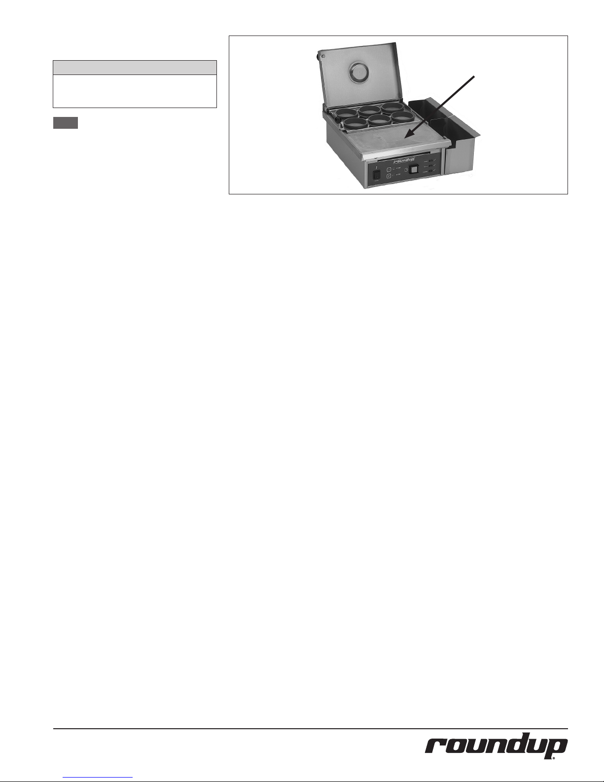
temperature at the middle of the
Platen surface (Figure 4). The
temperature should be 250°F–300°F
(121°C–149°C).
If temperature is within range, proceed to Step 4.
If temperature is above or below the
proper calibrated range, call your
Authorized Service Agency.
4. Turn the power o.
5. Reinstall cover and Egg Rack and Top
Cover.
Grill
Platen
Figure 4. Grill Platen (ES-600 Shown)
P/N 1010883 REV. L 12/15 9
Page 10
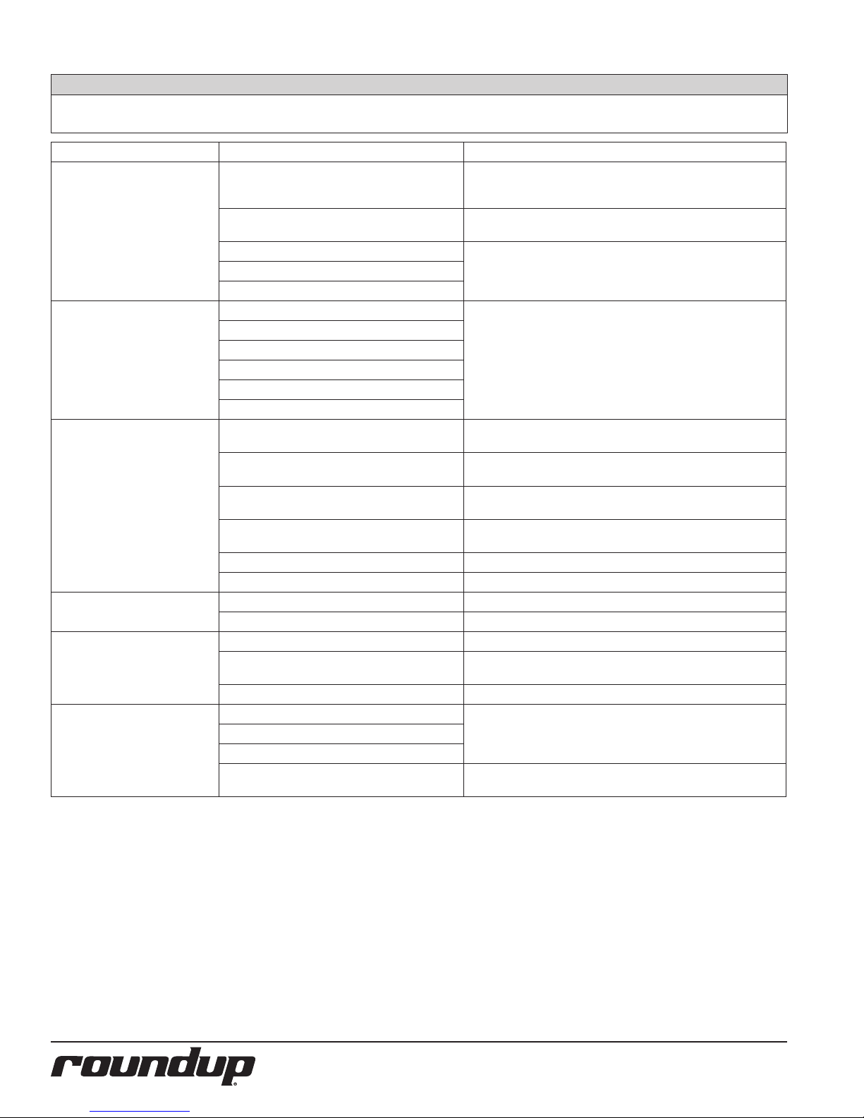
TROUBLESHOOTING
WARNING
To avoid possible personal injury and/or damage to the unit, inspection, test and repair of electrical equip-
ment should be performed by qualied service personnel. The unit should be unplugged when servicing.
Problem Possible Cause Corrective Action
Unit fails to operate and control
panel lights fail to signal on.
Unit fails to heat. Loose connections. Contact your maintenance person or an
Eggs do NOT cook
properly.
Eggs sticking to Platen. Dirty Platen. Clean Platen.
Eggs sticking to Egg Rings. Insucient butter being used. Refer to the Operating section of this manual.
Not signaling on “Bacon” or
“Ready”.
No power/low power. Make sure the power is on and the power cord
Inoperable electrical outlet. Plug the power cord into a dierent outlet of same amperage
Inoperable power switch. Contact your maintenance person or an
Inoperable power cord.
Loose connections.
Inoperable Platen.
Low voltage.
Inoperable Hi-Limit Thermostat.
Inoperable Thermocouple.
Inoperable Solid State Relay.
Using refrigerated eggs and TIME 1 button
selected.
Using room temperature eggs and TIME 2 button
selected.
Incorrect amount of water added to trough in
cover.
Platen temperature too low or too high. Check the Platen temperature according to the Maintenance sec-
Loose connections. Contact your Authorized Service Agency.
Unit/table is not level Level the table and unit as necessary.
Insucient butter being used. Refer to the Operating section of this manual.
Dirty Egg Rings. Clean the Egg Rings but do NOT use an
Inoperable Egg Ring. Replace Egg Ring.
Inoperable indicator light or audio signal. Contact your maintenance person or an Authorized Service
Inoperable control board.
Loose connection.
Bacon Timer is disabled. Enable Bacon Timer according to the Operation section of this
is locked into place. Check the main circuit
breakers.
rating.
Authorized Service Agency.
Authorized Service Agency.
Use TIME 2 button when using refrigerated eggs.
Use TIME 1 button when using room temperature eggs.
Fill trough in cover with water before starting time cycle.
tion of this manual.
abrasive scrubbing pad.
Agency.
manual.
P/N 1010883 REV. L 12/1510
Page 11
Control Board LEDs
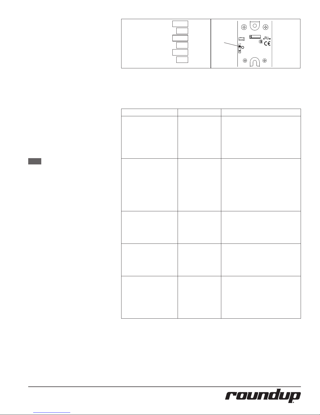
The control Board has three on board LEDs
(Figure 5) to determine the status of the unit
and to assist in troubleshooting.
Green (Diagnostic): This LED should be o
in normal operation. If any of the 5 potential faults are detected by the Control
Board, this LED will repeatedly blink either
1 through 5 times with a 2-second pause
in between (see the Green LED Blink Codes
section below).
Yellow (Audio): When lit, this LED indicates
that the Control Board is supplying approximately 10-15 VDC to the audio signal.
The audio signal should sound with this LED
is lit.
Red (Heat): When lit, this LED indicates that
the Control Board is calling for heat by supplying VDC to terminals 3(+)4(-) of the Solid
State Relay. When o, this LED indicates that
the grill Platen is up to operating temperature and satised.
NOTE: During heat mode, this Red LED
is very dim, so it may be dicult
to verify if the Control Board
is or is not calling for heat. It is
recommended that you observe
the small round green LED on the
Solid State Relay (Figure 6) for
mode and diagnostic purposes.
When the green LED on the Solid
State Relay is on, it means that
the Control Board is calling for
heat. When o, it means that
the Control Board is NOT calling
for heat. Typically, the VDC at
the Solid State Relay will be less
than 1.0 VDC when measured,
but may vary because of dierent quality VOMs. Therefore, it is
recommended that you do NOT
attempt to measure the VDC at
the Solid State Relay for diagnostic purposes.
YELLOW
BUZZ
STATUS
HEAT
GREEN
RED
R17
CR5
R18
R20
CR3
CR4
Solid State
Relay
LED
TUV
PRODUCT SERVICE
1/L1
Bauart
.
gapruit
4/A2-
50 AMP 24-280 VAC
Crouzet
GN
84137220
3-32 VDC
Figure 5. Control Board LEDs Figure 6. Solid State Relay
Green LED Blink Codes
Number of Blinks Cause(s) Unit’s State and Resolution
The Green LED blinks on
and o 1 time, pauses for 2
seconds, and repeats.
The Green LED blinks on
and o 2 times, pauses for 2
seconds, and repeats.
The Green LED blinks on
and o 3 times, pauses for 2
seconds, and repeats.
The Green LED blinks on
and o 4 times, pauses for 2
seconds, and repeats.
The Green LED blinks on
and o 5 times, pauses for 2
seconds, and repeats.
The EEPROM memory
on the Control Board
is corrupted.
The ambient temperature within the control
compartment has
exceeded 155 ºF (68
ºC). Verify that there is
proper air ventilation
all around the unit
and that it is not near
a signicant heat
source.
Open or disconnected
Thermocouple.
The supply voltage to
the unit is below 160
VAC or above 265 VAC.
The 50/60 Hz signal
has been lost due to
a disconnected or an
open wire harness/
wiring on the AC
Isolator Board, or from
the AC Isolator Board
to the Control Board.
In this state, the unit turns o the control
Signal to the Solid State Relay and disables
all front buttons and lights. The unit will
not heat up. This continues until the defaults are reloaded into memory. To reload
defaults, turn the unit o, press and hold
the TIME 2 button, turn the unit on, and
release the button.
In this state, the unit turns o the control
signal to the Solid State Relay and disables
all front buttons and lights. The unit will
not heat up. This continues until the
ambient temperature within the electrical
compartment drops below 140°F (60°C)
and the unit is turned o and back on.
In this state, the unit turns o the control
signal to the Solid State Relay and disables
all front buttons and lights. The unit will
not heat up. This continues until the
Thermocouple is reconnected or replaced,
and the unit is turned o and back on.
In this state, the unit turns o the control
signal to the Solid State Relay and disables
all front buttons and lights. The unit will
not heat up. This continues until the supply
voltage is within the proper limits and the
unit has been turned o and back on.
In this state, the unit turns o the control
signal to the Solid State Relay and disables
all front buttons and lights. The unit will
not heat up. This continues until the 50/60
Hz signal is reapplied and the unit is turned
o and back on.
2/T1
R
+3/A1
P/N 1010883 REV. L 12/15 11
Page 12
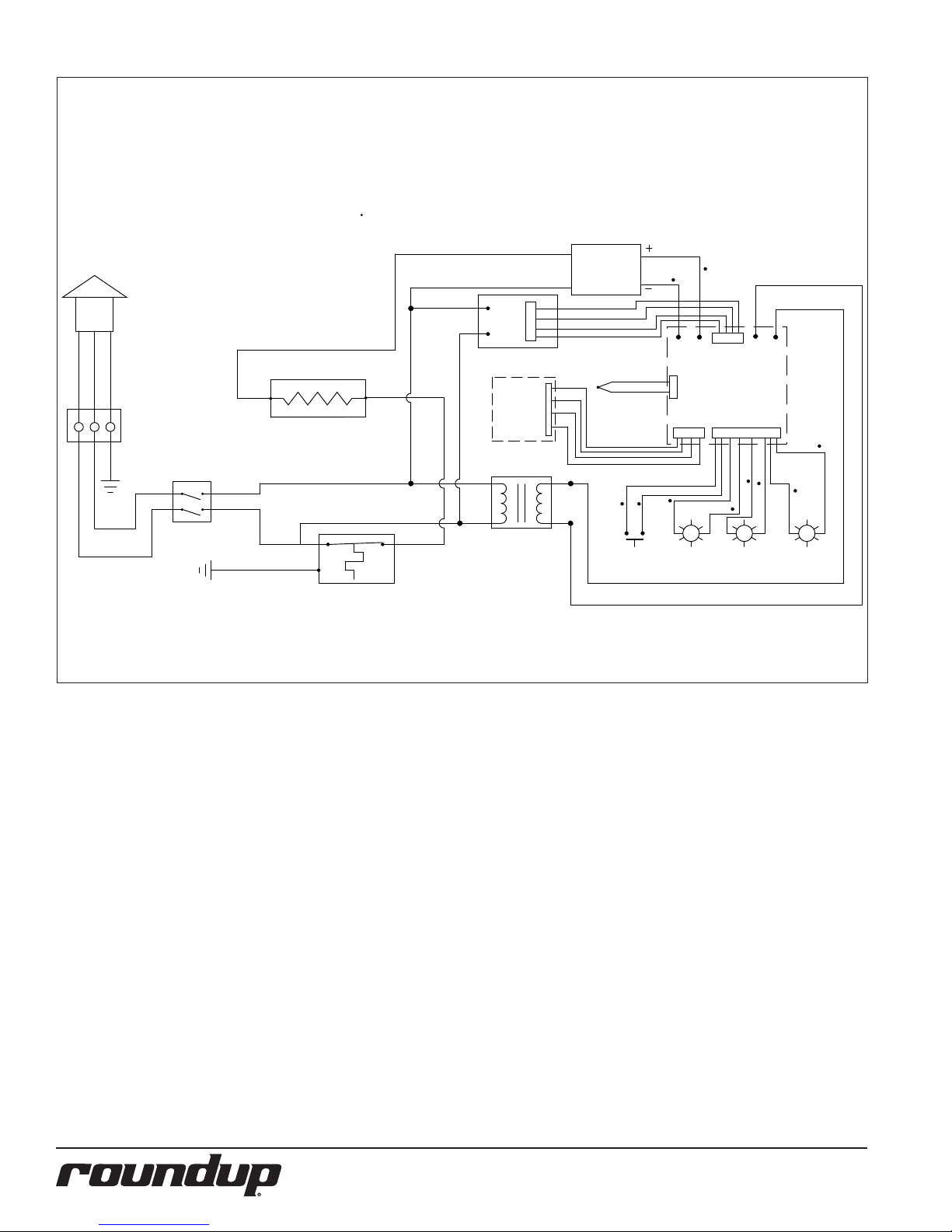
WIRING DIAGRAM
SWITCH
MOMENTARY
COOKING
BACON
READY
1
2
T1
T2
SSR
ISOLATOR BOARD
P4P3
P1
P2
T1
T2
CORD
POWER
WHT/BLU
BLK/BRN
GRN-YEL
GRN/
HEATER
NOTE: ALL WIRES TO BE 14 GA. TFE-200°C
22 GA. TFE-200°C
UNLESS OTHERWISE SPECIFIED.
# 18 GA. TFE-200°C
T3T4
COUPLE
THERMO-
SWITCH
BOARD
230VAC 12VAC
TRANSFORMER
GRN
GND
GND
THERMOSTAT
HI-LIMIT
TERMINAL
BLOCK
CONTROL
BOARD
BLK
WHT
WHT
BLK
WHT
WHT
BLK
BLK
YEL #
YEL #
WHT
GRN
ORG
BLK
GRN
BLK
BLUE
BLK
RED
BLK
YEL
BLK
4
3
21
4 5
P/N 1010883 REV. L 12/1512
Page 13
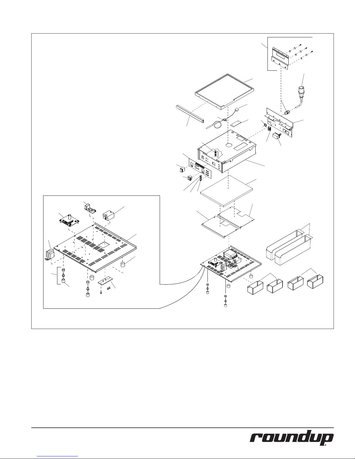
REPLACEMENT PARTS
76
30
3
66
8
1
54
31
51
53
59
60
63
57
62
23
52
2
32
61
18
4
29
64
25
5
26
58
55
24
81
6
7
33
69
P/N 1010883 REV. L 12/15 13
Page 14
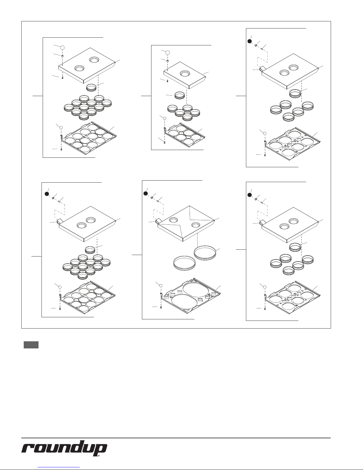
28
65
28
65
48
9
27
14
34
10
19
28
65
15
48
34
27
20
45
74
11
48
16
35
27
21
45
28
65
48
74
12
27
45
17
34
13
19
28
65
48
74
27
45
18
36
78
22
45
28
65
48
74
27
45
79
80
77
NOTE: Item 1 for Mfg. No.
9300132 uses a dierent Left Side Panel than
other units contained
in this manual. This allows the power cord for
9300132 to be located on
the Left side of the unit
rather than on the front
of the unit. The new Left
Side Panel part numbers
is 0506673.
P/N 1010883 REV. L 12/1514
Page 15

Replacement Parts can be purchased from an authorized dealer. Contact
A.J. Antunes & Co. at 1-630-754-1000 or toll free in the United States at 1-800-253-2991.
Item Part # Description Qty.
1 0021327 Nose Piece Weldment 1
2 210K230 Bumper, Recess Leg 1” (Set
of 4 including 4 screws)
3 7000379 Grill Platen 1
7000674 Grill Platen (Mfg. No.
9300593 Only)
4 040P138* Lock-nut, Conduit - 1/2”
NPT
5 040K251 Strain Relief Kit 1
6 2180270 Service Pan (For Mfg. No.
9300530 & 532)
7 2180277 Service Pan (For. Mfg. No.
9300534, 574, & 575
8 0502900 Bracket, Sensor 1
9 7000363 Cover, Rack & Ring
Assembly (Incl. All Shown)
ES-1200
10 7000261 Cover, Rack & Ring
Assembly (Incl. All Shown)
ES-600
11 7000835 Cover, Rack & Ring
Assembly (Incl. All Shown
(ES-604) (except Mfg. No.
9300593)
12 7000690 Cover, Rack & Ring
Assembly (Incl. All Shown)
(For Mfg. No. 9300534
only)
13 7000635 Cover, Rack & Ring
Assembly (Incl. All Shown)
ES-602
14 7000541 Cover, 12 Egg (Incl. #28, 48,
& 65) ES-1200
15 7000453 Cover, 6 Egg (Incl. #28, 48,
& 65) ES-600
16 7000836 Cover, 4” Egg Rings (Incl.
#28, 48, & 65) ES-604 (except Mfg. No. 9300593)
17 0012204 Cover, 12 Egg (Incl. #28, 48,
65, &74)
18 7000639 Cover, 8” Oval Ring ES-602
(Incl. #28, 48, 65, &74)
19 7000452 Rack, 12 Egg Ring (Incl. #27
& 45) ES-1200
20 7000454 Rack, 6 Egg Ring (Incl. #27
& 45) ES-600
21 7000837 Rack, 4” Egg Rings (Incl.
#27 & 45) ES-604 (except
Mfg. No. 9300593)
22 7000640 Rack, 8” Egg Rings (Incl #27
& 45) ES-602
23 0021324 Panel, Base 1
24 0021325 Housing, Main 1
25 0504075 Cover, Insulation 2
26 0021326 Rear Panel Weldment 1
1
1
1
2
2
1
1
1
1
1
1
1
1
1
1
1
1
1
1
Item Part # Description Qty.
27 2100137 Knob Ball 1
28 2100138 Knob Ball 1
29 0504078 Bracket, Hi-Limit 1
30 0700323 Power Cord Assembly
6-20P
31 1001100 Label, Control 1
31a 1001248 Label, Control (not shown)
(For Mfg. No. 9300534
Only)
31b 1001425 Label, Control (not shown)
(Mfg. No. 9300593 only)
31c 1001641 Label, Control (not shown)
(Mg. No. 9300621 only)
32 210K122 Adj. Leg Kit (Pack of 4) 1
33 210K108 Rubber Tip Kit (Pack of 4) 1
34 2130111 Egg Ring (Single)
ES-600/1200
213K101 Egg Ring (Pack of 6)
ES-600/1200
35 2130176 4” Egg Ring (single) ES-604
(except Mfg. No. 9300593)
213P179 4” Egg Ring (Pack of 6)
ES-604 (except Mfg. No.
9300593)
36 2130183 8” Round Egg Ring (Single)
ES-602
213P183 8” Round Egg Ring (Pack of
2) ES-602
37 306P113* Screw, Mach. #6-32 x 7/8”
Sltrshd
38 306P123* Screw, Mach. #6-32 x 5/8”
Sltrshd
39 306P130* Nut, Hex KEPS #6-32 1
40 308P102 Washer, Int. Tooth #8 1
41 308P104* Scr, Mach. #8-32 x 3/8”
Sltrshd
42 308P143* Nut, Hex KEPS #8-32 1
43 308P157* Screw, Tap #8-32 x 3/8” 1
44 310P102* Washer, Int Tooth Lock #10 1
45 310P09* Scr, Mach #10-32 x 3/8”
Sltrshd
46 310P136* Scr, Mach. #10-32 x 1 1/4”
Slpanhd
47 310P149* Scr, Mach #10-32 x 7/8”
Slpanhd
48 325P101* Stud, 1/4-20 x 1-1/2” 1
49 325P104* Washer, Flat 1/4” S/S 1
50 325P109* Scr, HXCAP 1/4-20 x 3/4” 1
51 4010137 Switch, Rocker (25A-250V) 1
52 4010187 Transformer, Stepdown
(240V/12)
53 4010190 Switch, Momentary 1
1
1
1
1
6/12
1/2
6
1
1
1
1
1
1
1
1
1
1
Item Part # Description Qty.
54 4010193 PC-Board, Switch-Two
Button
55 7000272 Thermostat, Hi-Limit 1
57 7000370 Solid State Relay 1
58 7000137 Terminal Block, 3-pole 1
59 4060362 LED, Snap-in (Green
- Ready)
60 4060363 LED, Snap-in (Yellow
- Cooking)
61 4060385 LED, Snap-in (Blue - Bacon) 1
62 7000520 Control Board 1
62a 7000691 Control Board Kit (For Mfg.
No. 9300534 only)
62b 7001129 Control Board Kit (For Mfg.
No. 9300621 only)
63 7000391 A/C Line Isolator Board 1
64 0400337 Insulation 1
65 2120111 Spacer 1
66 4050214 Thermocouple 1
67 2180111 Plastic Dispensing Bottle
(Not shown)
68 213K115 Spatula, Scraper, and Brush
Kit (Not Shown)
69 0011251 Heat Sink Assembly 1
70 0700648 Wire Set, Main (Not Shown) 1
71 0700655 Wire Harness/PCB-LEDs
(Not Shown)
72 0700656 Wire Harness/PCB-Isolator
BD (Not Shown)
73 0700657 Wire Harness/PCB-2 Button
BD (Not Shown)
74 0021401 Handle Weldment 1
75 300P102* Nut, Speed #8-32 “U” 1
76 7000838 Back Bracket Assembly Kit
(All ES-604 units except
Mfg. No. 9300593).
77 7001020 Egg Rack Assembly Kit
3.75” Rings (Mfg. No.
9300593 Only)
78 7001021 Egg Rack & Cover Kit - 3.75”
Rings (Mfg. No. 9300593
Only)
79 7000836 Cover & Hinge Kit (Mfg. No.
9300593 Only)
80 213P188* Egg Ring 3.75” Pkg of Six
(Mfg. No. 9300593 Only)
81 2180259 Scrap Tray (For Mfg. No.
9300593 Only)
*Available in packages of 10 (ten)
1
1
1
1
1
1
1
1
1
1
1
1
1
1
1
2
P/N 1010883 REV. L 12/15 15
Page 16
LIMITED WARRANTY
Equipment manufactured by Roundup Food Equipment Division of A.J. Antunes & Co. has been constructed of the nest
materials available and manufactured to high quality standards. These units are warranted to be free from electrical and
mechanical defects for a period of one (1) year from date of purchase under normal use and service, and when installed in
accordance with manufacturer’s recommendations. To insure continued operation of the units, follow the maintenance
procedures outlined in the Owner’s Manual. During the rst 12 months, electro-mechanical parts, non-overtime labor,
and travel expenses up to 2 hours (100 miles/160 km), round trip from the nearest Authorized Service Center are covered.
1. This warranty does not cover cost of installation, defects caused by improper storage or handling prior to placing of
the Equipment. This warranty does not cover overtime charges or work done by unauthorized service agencies
or personnel. This warranty does not cover normal maintenance, calibration, or regular adjustments as specied
in operating and maintenance instructions of this manual, and/or labor involved in moving adjacent objects to
gain access to the equipment. This warranty does not cover consumable/wear items. This warranty does not cover
damage to the Load Cell or Load Cell Assembly due to abuse, misuse, dropping of unit/shock loads or exceeding
maximum weight capacity (4 lbs). This warranty does not cover water contamination problems such as foreign
material in water lines or inside solenoid valves. It does not cover water pressure problems or failures resulting
from improper/incorrect voltage supply. This warranty does not cover Travel Time & Mileage in excess of 2 hours
(100 miles/160 km) round trip from the nearest authorized service agency.
2. Roundup reserves the right to make changes in design or add any improvements on any product. The right is always
reserved to modify equipment because of factors beyond our control and government regulations. Changes to
update equipment do not constitute a warranty charge.
3. If shipment is damaged in transit, the purchaser should make a claim directly upon the carrier. Careful inspection
should be made of the shipment as soon as it arrives and visible damage should be noted upon the carrier’s receipt. Damage should be reported to the carrier. This damage is not covered under this warranty.
4. Warranty charges do not include freight or foreign, excise, municipal or other sales or use taxes. All such freight and
taxes are the responsibility of the purchaser.
5. This warranty is exclusive and is in lieu of all other warranties, expressed or implied, including any implied warranty
or merchantability or tness for a particular purpose, each of which is hereby expressly disclaimed. the remedies
described above are exclusive and in no event shall roundup be liable for special consequential or incidental damages for the breach or delay in performance of this warranty.
 Loading...