


Roundshot VR Drive
Instruction Manual
Firmware version 2.023
23/05/2019Roundshot VR Drive Instruction Manual – Firmware Version 2.023 0
23/05/2019Roundshot VR Drive Instruction Manual – Firmware Version 2.023 1

CONTENTS
23/05/2019Roundshot VR Drive Instruction Manual – Firmware Version 2.023 2
Page
1. System Overview
1.1 Hardware components + accessories 4
1.2 Software components 13
2. First Steps With Your VR Drive
2.1 Setting up the VR Drive hardware 16
2.1.1 Roundshot VR Drive “full” 17
2.1.2 Attaching y-motor on bottom plate 24
2.1.3 Roundshot VR Drive “turntable” 26
2.1.4 External light meter 28
2.1.5 Radio control unit 30
2.1.6 Wifi router for remote control 33
2.2 Setting up the digital camera 35
2.3 Setting up the VR Drive software 36
2.4 Navigation 38
2.5 Starting/stopping the VR Drive 46
3. Program Management
3.1 Overview 47
3.2 Program Wizard 49
3.2.1 Wizard workflow for quality, speed and HDR modes 50
3.2.2 Wizard workflow for turntable mode 53
3.2.3 Wizard workflow for timelapse and video modes 53
4. Program Editing
4.1 Editing in quality, speed and turntable modes 55
4.2 Editing in timelapse and video modes 68
4.3 Editing in HDR mode 71
4.4 USB Settings 76
4.5 Auto exposure settings 79
4.6 Settings 80
4.6.1 Settings/general 80
4.6.2 Settings/database 91
4.6.3 Settings/service menu 100

CONTENTS
23/05/2019Roundshot VR Drive Instruction Manual – Firmware Version 2.023 3
Page
5. Workflow
5.1 Nodal point adjustment procedure 101
5.2 VR Drive image capture – speed vs. quality mode 106
5.3 Creating HDRs – quality vs. HDR mode 107
5.4 Roundshot Image Bundler 109
5.5 Extracting xml files manually 112
5.6 Stitching 113
5.7 Masking the nadir 118
5.8 Conversion to web formats 119
6. Tips and Tricks
6.1 Hardware realignment of nodal rail with y-motor 120
6.2 Reducing vibrations: mirror prerelease + Liveview mirror lock-up 121
6.3 Gigapixel photography 122
6.4 Selective image release + program resume: x/y repeat or x/y resume 123
6.4 Creation of object movies 124
6.5 Using long exposure times 126
6.6 Using the VR Drive light meter 127
6.7 Video vs. timelapse mode 131
6.8 Working with presets 135
6.9 Frequently asked questions 136
7. Maintenance & Warranty
7.1 Recharging the VR Drive 139
7.2 Transport & storage 139
7.3 Touch screen calibration 140
7.4 International Warranty 141
7.5 Software update: “Club VR Drive” 142
7.6 Upgrades: Adding new software modes 146
7.7 Return of equipment / recycling 147
8. Technical Data 148

1. System Overview
The Roundshot VR Drive is delivered in a carton box with foam protection or in an
optional explorer case and contains the following items:
23/05/2019Roundshot VR Drive Instruction Manual – Firmware Version 2.023 4
VR Drive x-
motor
Universal
charger
(110-220V)
VR L-bracket
with VR Drive
y-motor (with
nodal rail
clamp) and
nodal rail
VR Drive
release cable
VR Drive
accessories
(connection
cables, tools,
spirit level)
1.1 Hardware components + accessories

Correctly assembled VR Drive
with L-bracket:
23/05/2019Roundshot VR Drive Instruction Manual – Firmware Version 2.023 5
1.1 Hardware components + accessories (continued)
• Camera points in opposite direction of
touch screen
• y-motor on the right-hand side
• After turning the VR Drive off, the camera
points into the sky at +90° (zenith)
If the camera points to the ground after turning the VR Drive off, the nodal rail with
the camera was attached from the wrong side. This will invert the image capturing
sequence with the effect that the xml file for stitching will not be valid.
23/05/2019Roundshot VR Drive Instruction Manual – Firmware Version 2.023 6
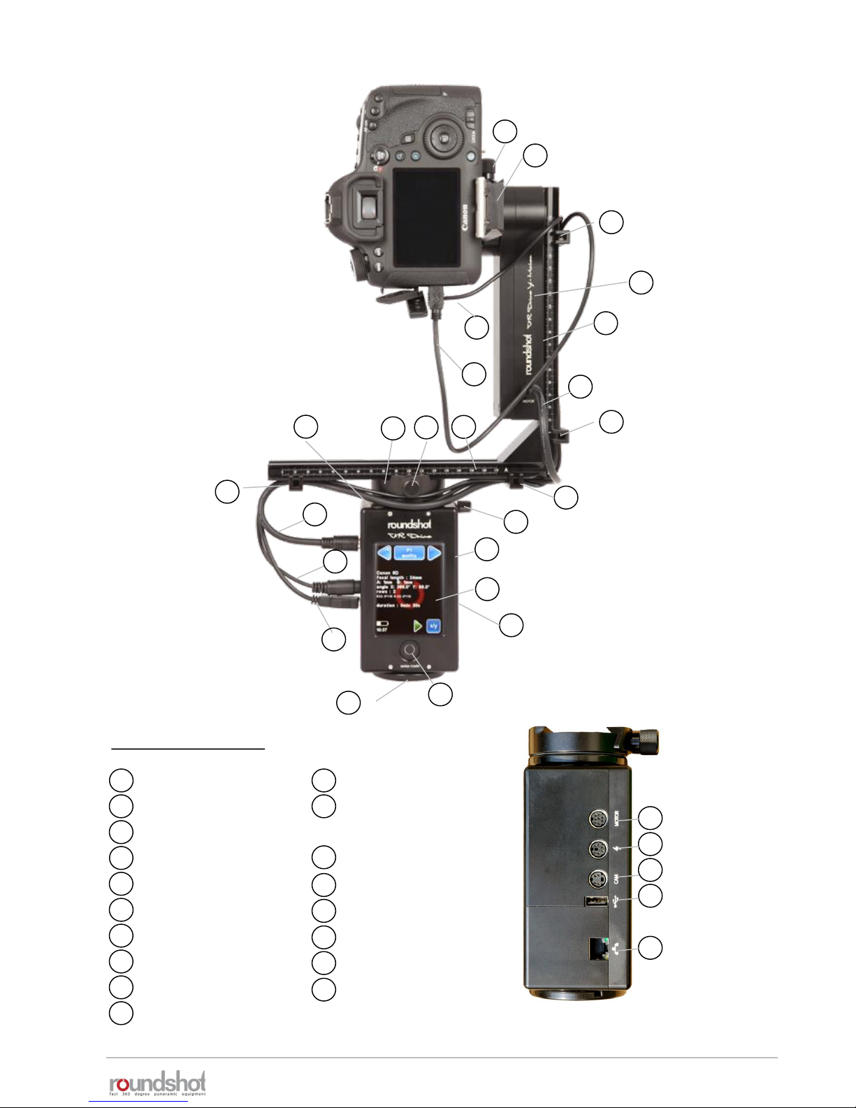
1.1 Hardware components + accessories (continued)
Roundshot VR Drive “full”
VR Drive x-motor
touch screen
on/off button
VR Drive y-motor
quick adaptor
quick adaptor release
VR bracket lock
VR bracket
nodal rail
nodal rail clamp
x-motor cable
charging unit
release cable
USB cable
Ethernet (to
connect wifi
module)
VR Drive components
1
2
3
4
5
6
7
8
9
10
11
12
13
1
2
3
4
5
8
9
13
19
20
21
22
23
17
15
release cable (optional)
USB cable for camera
control (optional)
motor cable x-y
spirit level
tripod mount (3/8’’)
VR Drive y-motor
cable clips
socket for radio control
unit (receiver)+ for light
meter
14
15
cables/plugs
6
16
10
11
18
12
17
18
7
11
12
13
14
16
17
17
17

23/05/2019Roundshot VR Drive Instruction Manual – Firmware Version 2.023 7
1.1 Hardware components + accessories (continued)
Roundshot VR Drive “full” – with bottom plate for fixed centre point (adjustable)
25
24
Side cover to protect cables
VR bottom plate – adjustable 32-70mm – for fixed centre point
Allen key 4mm for attaching/removing camera to nodal rail,
attaching/removing y-motor to VR bracket, locking/releasing VR
Drive x-motor on tripod
Allen key 3/16’’ for removing/attaching or fine-tuning y-motor
26
25
26
27
24
27
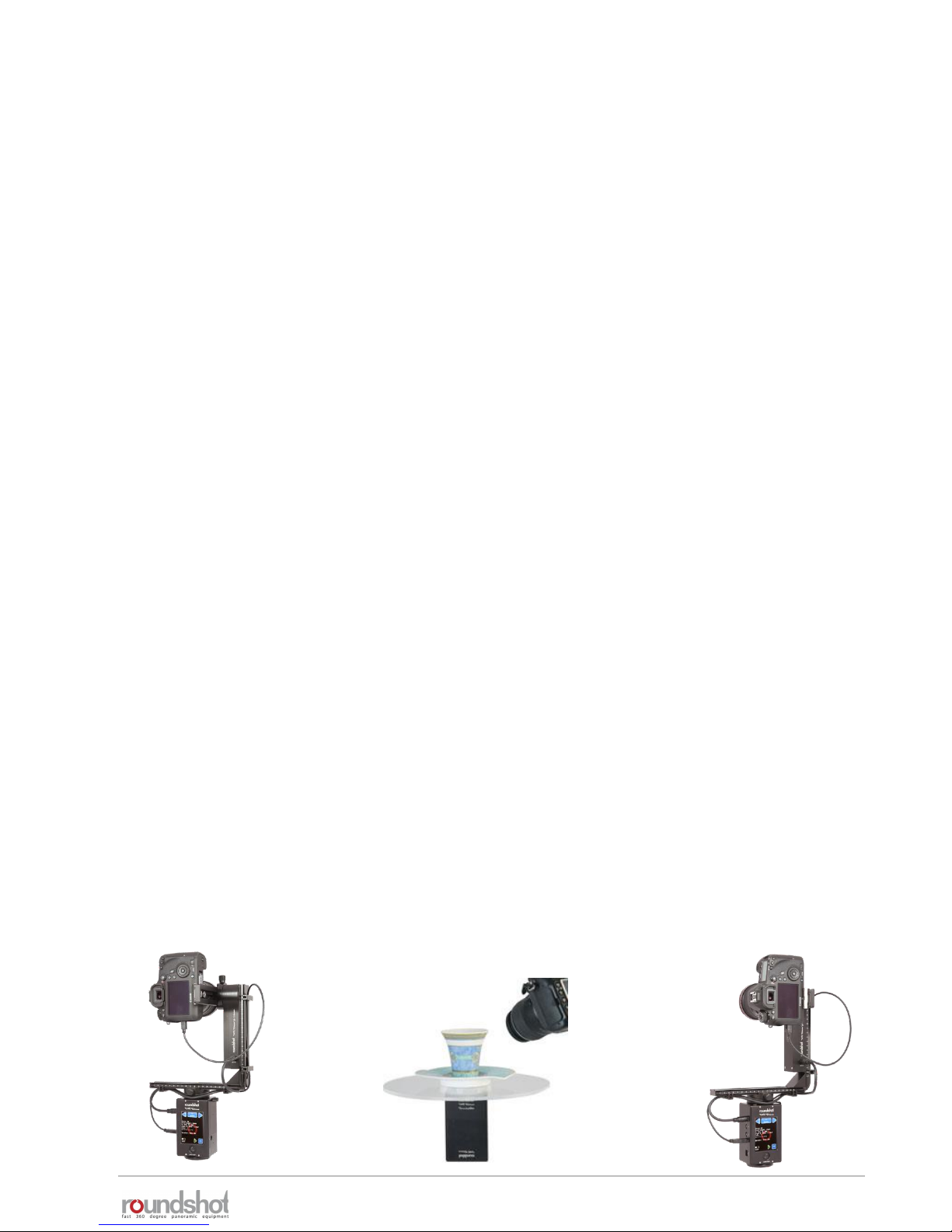
In this set-up with special bottom plate, the y-motor is inverted (at the Seitz factory)
so that it can be attached on the left-hand side rather than on the right. This has the
advantage that all cables can be secured under the side cover and do not pass over
the motor. This is a practical set-up for single camera situations where the center
point will always be identical.
VR Drive with bottom plate, inverted y-
motor (on left) and with slide cover to
protect cables
VR Drive with bottom plate, standard
VR holder and with standard y-motor
(on right)

23/05/2019Roundshot VR Drive Instruction Manual – Firmware Version 2.023 8
1.1 Hardware components + accessories (continued)
Roundshot VR Drive “semi” – with x-motor only and manual tilting
28
28
y-clamp for manual tilting
23/05/2019Roundshot VR Drive Instruction Manual – Firmware Version 2.023 9
1.1 Hardware components + accessories (continued)
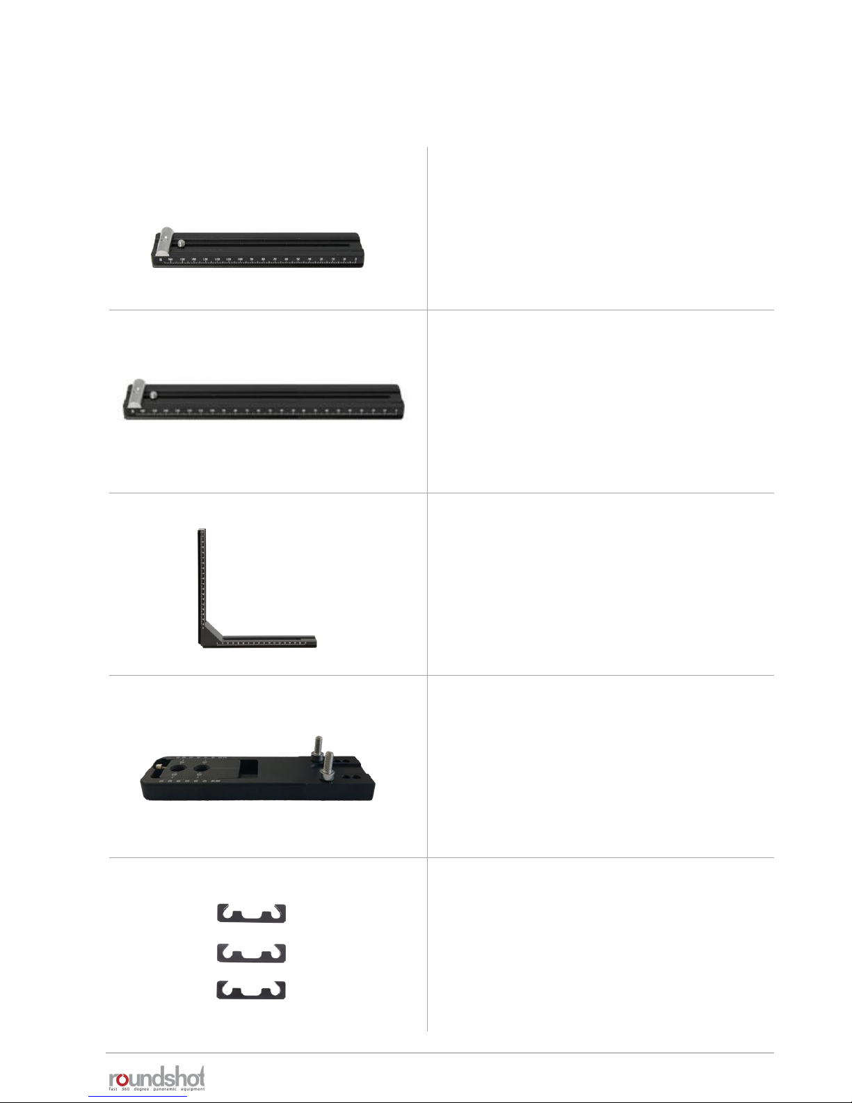
Overview of accessories
Short nodal rail (for fisheye lenses)
Additional VR bracket – for example for
video mode to attach the camera in
landscape orientation
Long nodal rail – 220mm (for long +
heavy lenses)
VR bottom plate
adjustable 32-70mm to fix center point
cable clips
to attach cables on VR bracket
23/05/2019Roundshot VR Drive Instruction Manual – Firmware Version 2.023 10
1.1 Hardware components + accessories (continued)
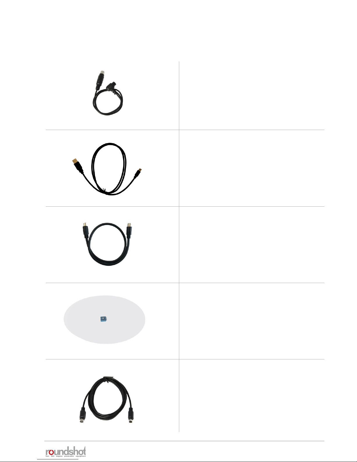
Overview of accessories (continued)
Camera release cables
(please check our website for list of
compatible cameras)
Turntable with 28cm or 50cm diameter
Extension cable (2m) for turntable
USB cables
for USB-compatible cameras (please check
our website for list of compatible cameras)
x-y motor cable

23/05/2019Roundshot VR Drive Instruction Manual – Firmware Version 2.023 11
1.1 Hardware components + accessories (continued)
Overview of accessories (continued)
Wifi router – to transfer the contents of
the touch screen on a wifi-connected
device (smart phone, tablet, computer)
Radio control unit
Universal charger 110-220V
External light meter – to automate
image-taking process – requires USBcompatible camera
Explorer case 4412 B
Including VR Drive foam
insert and explorer foam

23/05/2019Roundshot VR Drive Instruction Manual – Firmware Version 2.023 12
1.1 Hardware components + accessories (continued)
Overview of accessories
linear rail
y-clamp for manual tilting
(VR Drive semi)
spirit level
roundshot USB key –
for firmware updates

23/05/2019Roundshot VR Drive Instruction Manual – Firmware Version 2.023 13
1.2 Software components
1.2.1 VR Drive firmware options
The VR Drive quality mode represents the
base functionality for panoramas up to 360°
(or more). The camera is stopped in every
position. This mode is used for panoramas
with difficult lighting conditions (indoors)
and for bracketing of HDR images.
In speed mode the camera is rotated non-
stop, ideal for moving scenes outdoors. This
fast-release mode requires a fast shutter
speed which is computed by the VR Drive in
function of camera/lens, sensor size, focal
length and speed of rotation.
In turntable mode
the camera
captures images of
a rotating object on
a turntable for
object movies.
Never miss an
image, perfect
positioning!
In timelapse mode the VR Drive
releases a sequence of images
which are then composed into a
timelapse movie. Three capture
formats are possible: 360°
rotation,linear movement along
a rail or dolly.
In "HDR mode" the camera is controlled by the VR Drive, enabling
wider bracketing for 32-bit HDRs. The VR Drive "HDR mode" controls
the camera software directly and allows a virtually unlimited
bracketing range. It is an "all-in-one" solution - no additional devices
are needed.
In video mode the VR Drive moves
the camera in the x/y space in a
linear trajectory. It is possible to
control speed, acceleration, duration
of the movement and pauses.
23/05/2019Roundshot VR Drive Instruction Manual – Firmware Version 2.023 14
1.2 Software components (continued)
1.2.2 VR Drive firmware upgrades
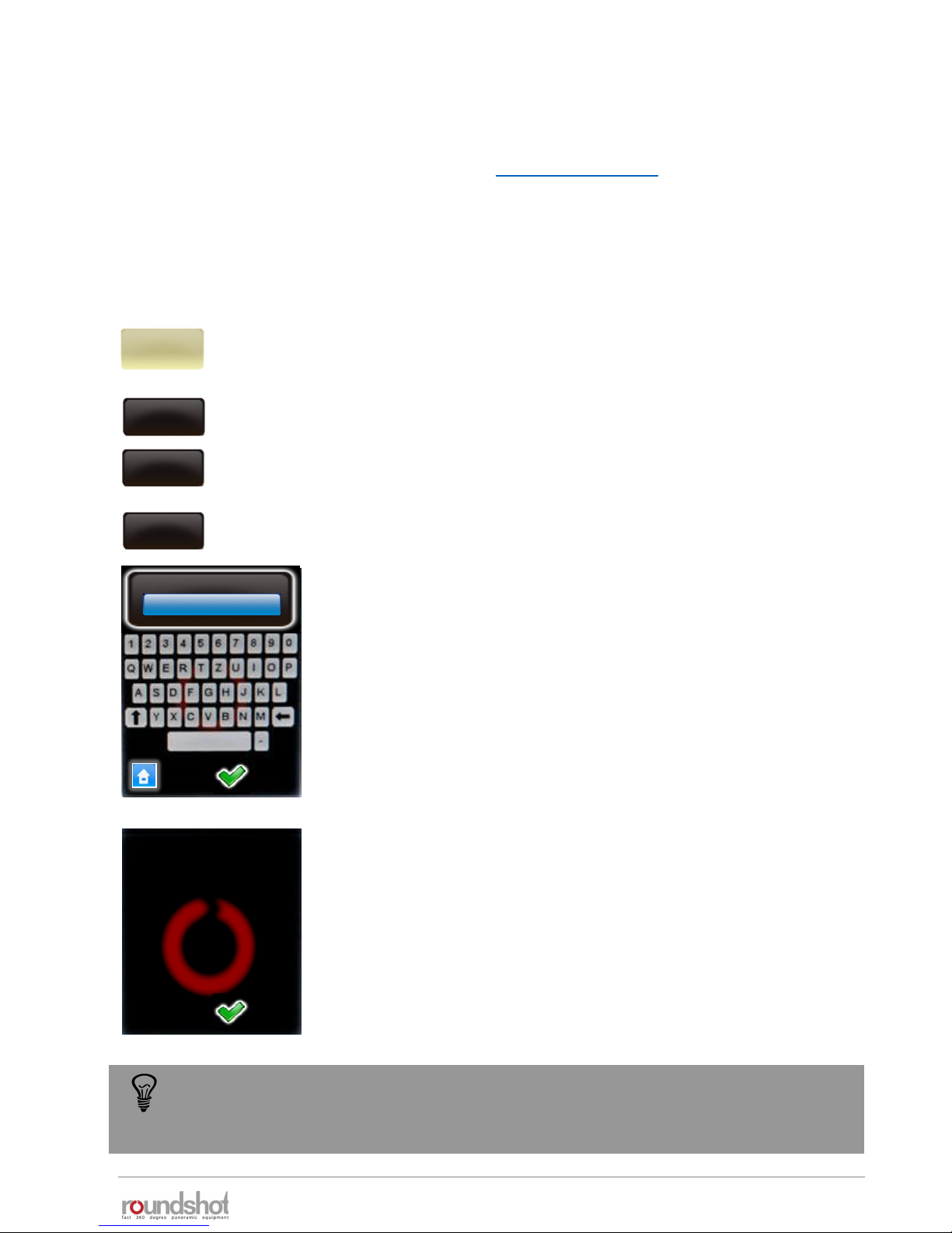
Click on “key” to display the software key.
Enter the new software key.
Confirm with “OK”.
After entering a valid key, the software displays the available
software modes.
When entering an invalid key, the last valid key will be loaded.
Confirm with “OK”.
Software upgrades can be ordered after initial purchase of your VR Drive from your distributor
or directly from Seitz Roundshot on our website www.roundshot.com.
Once your purchase is confirmed, we will send you a 16-digit key by email which is linked to the
unique hardware ID (serial number) of your VR Drive. This key activates the relevant software
modes.
Click on “settings” to access the VR Drive settings menu.
Click on “general”.
Click on “software”.
settings
general
software
key
key
A98DF1DB3C0D4655
key
The software key is
valid. The following
modes are now
available:
quality
speed
turntable
video
To try out a new software mode, request a temporary software key by Roundshot. It
will be valid for a limited time (30 days, 60 days…) and allows non-restricted use of
all software functions.

23/05/2019Roundshot VR Drive Instruction Manual – Firmware Version 2.023 15
1.2 Software components (continued)
1.2.3 External software
Roundshot Image Bundler
The Bundler program is a free software tool which is
available free of charge from the roundshot “club” as a
download. Designed for USB-compatible cameras, it
automatically groups images into projects and creates
an xml file to support faster and more accurate
stitching.
PTGUI Stitching software
PTGUI is a stitching software enabling fast GPU-based
processing of spherical and cylindrical panoramas.
Thanks to the xml file, it seamlessly integrates with the
VR Drive.
FSP Viewer
Once the panorama is rendered, it can be loaded in FSP
Viewer for a fast spherical or cylindrical preview.
Pano2VR
Pano2VR is a comprehensive software to convert flat
panoramas into interactive virtual tours.
Object2VR
With Object2VR a series of turntable images is
converted into an object movie.
KR Pano
KR Pano is a web viewer and programming interface to
create virtual tours.
Included in VR
Drive product
VR-EASY
Develop 360° tours easily and quickly with VR-EASY. This
software is cloud-based, optimised for many devices and
browsers and allows flexible inserting of information,
images and graphics.

23/05/2019Roundshot VR Drive Instruction Manual – Firmware Version 2.023 16
2. First Steps With Your VR Drive
2.1 Setting up the VR Drive hardware
Your VR Drive is delivered in a compact shipping box with foam protection.
The shipping box consists of five compartments:
VR Drive
x-motor
Universal
charger
(110-220V)
VR bracket
with VR Drive
y-motor (or
nodal rail
clamp) and
nodal rail
VR Drive
release cable
VR Drive
accessories
(connection
cables, tools,
spirit level)

23/05/2019Roundshot VR Drive Instruction Manual – Firmware Version 2.023 17
2.1 Setting up the VR Drive hardware (continued)
Assemble your VR Drive “full” in the following way:
Open the quick adaptor release
and turn the VR bracket in position.
Place the VR Drive x-motor on
a tripod with a large (3/8’’)
thread. When using a tripod
with small thread (1/4’’) use
an adaptor ring inside the VR
Drive motor base.
When the VR Drive locks up
very tightly on the tripod, it
can be released with the
allen key
Slide the VR bracket with
attached y-motor into the
quick adaptor and close
the quick adaptor lock
tightly.
Close the quick adaptor release
tightly.
2.1.1 Roundshot VR Drive “full”
To avoid damage to the VR Drive gears we recommend that you attach the VR
Drive gently by hand and then lock it using the allen key. The same is true when
removing the VR Drive from the tripod.
Do not turn the VR bracket, when the quick adaptor is locked. Due to the high
leverage the VR Drive motor and the gears can be damaged.

23/05/2019Roundshot VR Drive Instruction Manual – Firmware Version 2.023 18
Adjust the height of the y-motor
using the allen key.
Make sure that there is enough
space for large cameras and lenses
when tilting downward -90°.
It is possible to slide the y-motor
up and fix it at the very top.
However, for stability purposes it
is better to keep the y-motor as
low as possible.
Now connect the y-motor cable
into the VR Drive x-motor.
Connect the other end of the
cable into the VR Drive y-motor
(front or rear).
2.1.1 Roundshot VR Drive “full” (continued)

23/05/2019Roundshot VR Drive Instruction Manual – Firmware Version 2.023 19
Attach your digital camera to the
nodal rail using the allen key.
Make sure that the camera is always attached at
the same position. We recommend sliding the
camera to the very rear (zero position). When
attaching the camera at different positions the
nodal points in the software will no longer be
correct.
If the nodal rail is not long enough (or longer
lenses) use a separate, longer nodal rail
(available on request).
Check that the rear of the camera is mounted straight at exactly 90° with the nodal rail:
wrong correct
2.1.1 Roundshot VR Drive “full” (continued)

23/05/2019Roundshot VR Drive Instruction Manual – Firmware Version 2.023 20
Slide the camera with the nodal rail
into the nodal rail clamp.
Close the nodal rail clamp lock.
Now check that the camera is exactly
level using the spirit level.
Check if the VR Drive x-motor is level
using the spirit level on the motor.
You can also attach the spirit level at the
side of the x-motor.
2.1.1 Roundshot VR Drive “full” (continued)
Connect the release cable and /or the USB
cable into the VR Drive x-motor

23/05/2019Roundshot VR Drive Instruction Manual – Firmware Version 2.023 21
Connect the other end of the cable into
the camera . Push it tightly into the socket.
2.1.1 Roundshot VR Drive “full” (continued)
To use the USB cable for image release, this USB feature needs to be activated in the
Program Wizard or in the program edit menu (USB parameters – USB cable
connected: on – release with USB cable: on).
If not, the images will be released via the electronic release cable.
When to use which cable?
electronic
release cable
USB
cable
• Quality mode
• Speed mode
• Turntable mode
• Timelapse mode
• Video mode
• HDR mode
The USB cable can only be used with USB-compatible cameras. For a list of compatible models
please check our website: www.roundshot.com.
It is also possible to use the USB cable for advanced USB features only and release the
images with the electronic release cable. This set-up is recommended for example when
using mirror prerelease in HDR mode.
-
-
Attach the cable clips on the VR bracket
to fasten all cables.

23/05/2019Roundshot VR Drive Instruction Manual – Firmware Version 2.023 22
2.1.1 Roundshot VR Drive “full” (continued)
VR Drive full with motor and USB cable
Standard case for controlled image release in
quality mode, turntable mode or HDR mode
Advantages:
• USB features (such as “Write IDs”, “release control”, “wait for
camera”) can be used
• Roundshot Image Bundler can be used
Disadvantages:
• Slower image release/processing, requires a small pause after
image to give camera firmware time for USB processing
• No “mirror prerelease” can be used – but for certain USB-
compatible cameras “permanent Liveview” (“mirror lock-up”)
can be used
VR Drive full with motor and electronic release cable
Used in speed mode for fast image release
Advantages:
• Fast image release
Disadvantages:
• No USB features and no Image Bundler
• “Mirror prerelease” can be used, but no “permanent Liveview”
(“mirror lock-up”)
VR Drive full with motor, USB cable and electronic release cable
Can be used in all modes to combine various features
Advantages:
• Fast image release of electronic cable can be used
• HDR mode or USB features can be used selectively
Disadvantages:
• USB features still require processing time in camera firmware

23/05/2019Roundshot VR Drive Instruction Manual – Firmware Version 2.023 23
2.1.1 Roundshot VR Drive “full” (continued)
When mounting the camera with nodal rail in the opposite direction, the xml file will
not be correct and the stitching will not work. Please also check section “Frequently
Asked Questions” for additional information on how to recover an incorrect xml.
Turn the VR Drive off.
If the default parking position has not been changed, the camera should now point +90°
towards the sky (zenith).
If the camera points -90° down to the ground (nadir), you have mounted the camera + nodal
rail in the opposite way on the nodal rail clamp (y-motor).

23/05/2019Roundshot VR Drive Instruction Manual – Firmware Version 2.023 24
2.1.2 Attaching y-motor on bottom plate
VR Drive with bottom plate, inverted y-
motor (on left) and with slide cover to
protect cables
VR Drive with bottom plate, standard
VR holder and with standard y-motor
(on right)
The VR bottom plate (for fixed camera centre position) can be mounted in two ways:
Requires
inversion of
y-motor at
Seitz factory
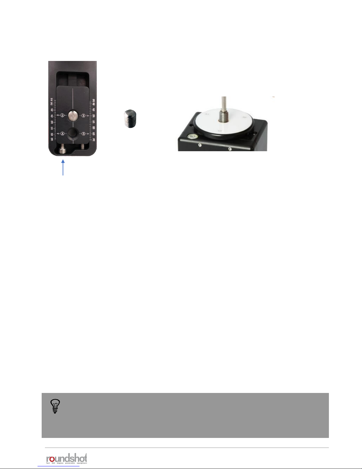
These two screws can be
placed in position “A” or
“B”
The VR Drive y-motor is attached on top of
the bottom plate using two screws.
“A”
“B”
23/05/2019Roundshot VR Drive Instruction Manual – Firmware Version 2.023 25
2.1.2 Attaching y-motor on bottom plate (continued)
The bottom plate is attached onto the VR Drive x-motor
using the 3/8’’ screw which is attached beneath the quick
adaptor (5).
Center the camera by turning the adjustment screws and by positioning the viewfinder cross
exactly in the middle of the 3/8’’ screw (rotation axis.
When the two screws are attached in position “A” as shown in the above example, read the
value on the left the 3/8’’ screw and the “A” symbol.
If position “B” is used, read the value on the right of the 3/8’’ screw and the “B” symbol.
Enter this value in the VR Drive program – as “A value”.
adjustment screws
Using the bottom plate is ideal when always using the same camera. On the other
hand, the VR bracket (L-bracket) is more convenient when flexibility in the choice of
camera and/or the vertical position (for example for long lenses/gigapixels) is
important.
23/05/2019Roundshot VR Drive Instruction Manual – Firmware Version 2.023 26
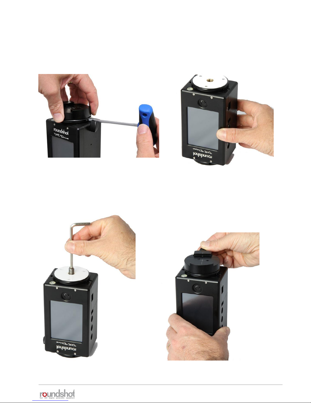
Assemble your VR Drive “turntable” in the following way:
2.1.3 Roundshot VR Drive “turntable”
Attach the VR Drive x-motor
upside-down on the tripod.
Attach the 3/8’’ thread.
Attach the quick adaptor.
Lock the quick adaptor release and
remove the quick adaptor from the VR
Drive x-motor by turning it anti-clockwise.
Hold the turntable with the allen key
without turning the allen key.

23/05/2019Roundshot VR Drive Instruction Manual – Firmware Version 2.023 27
2.1.3 Roundshot VR Drive “turntable” (continued)
Slide the turntable into the quick
adaptor and lock it firmly.
Your VR Drive “turntable” is now
ready.
The turntable is covered with a
protective foil on both sides.
Remove the protective foil
on both sides of the turntable
before use.
23/05/2019Roundshot VR Drive Instruction Manual – Firmware Version 2.023 28
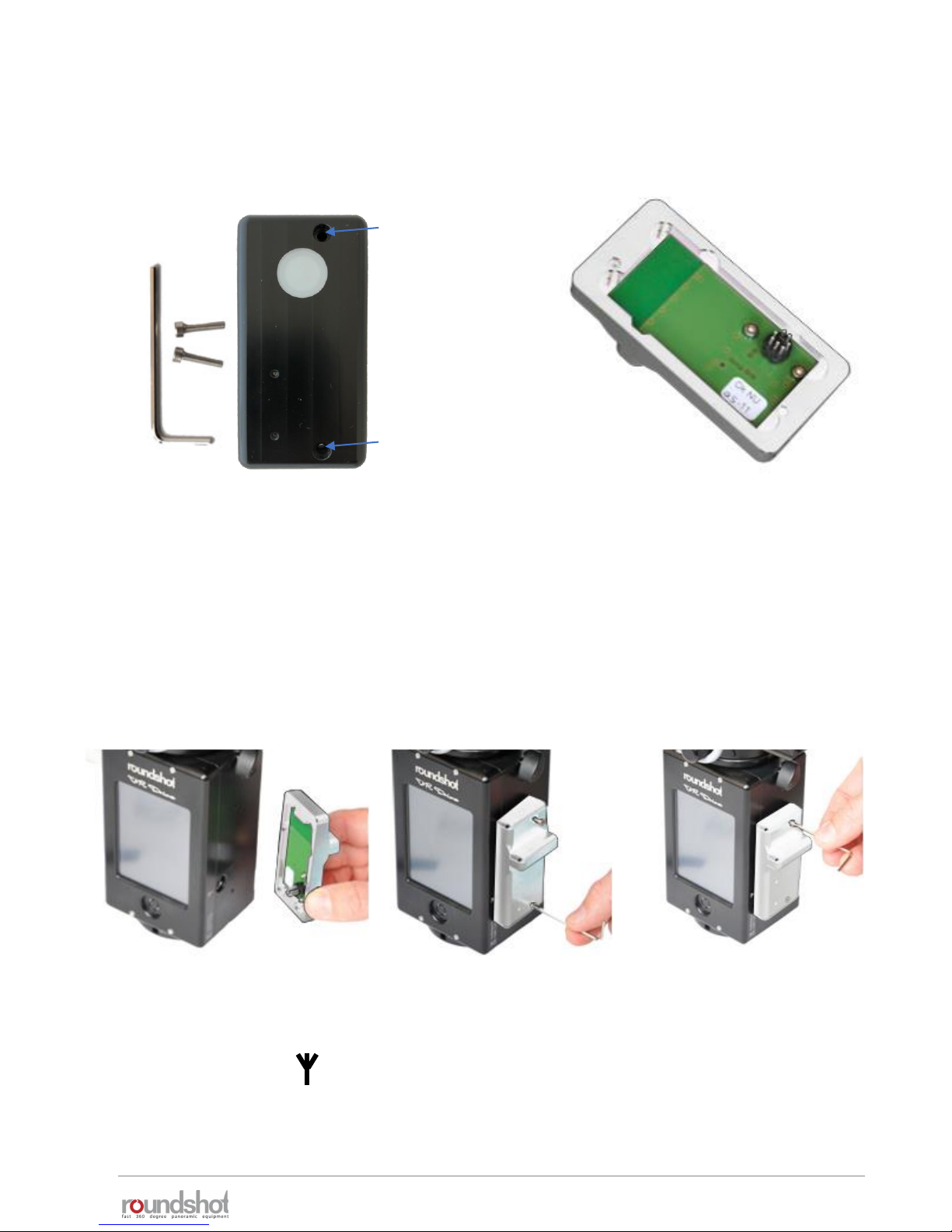
2.1.4 External light meter
The light meter sensor consists of the following parts:
Allen key with
screws
Light meter
sensor
Never place the light meter sensor
on the connector pins as they are
fragile.
Socket
for
upper
screw
Socket
for
lower
screw
Attach the light meter in the following way:
Insert the light meter
pins into the plug
marked with the
antenna symbol:
Insert the lower screw
and attach it with the
allen key.
Insert the upper screw
and attach it with the
allen key.
23/05/2019Roundshot VR Drive Instruction Manual – Firmware Version 2.023 29
Once the light meter sensor is attached, it will be automatically detected by the VR Drive.
If the camera used is compatible with the VR Drive USB control, The program wizard will directly
suggest automatic light metering options.
To manually activate automatic exposure functions
• Open the Edit menu
• Open the menu auto exposure settings
• Set the auto exposure parameter to on
• Set the other automatic exposure parameters (Strategy, ISO/ASA, aperture). More details are
available in the section Tips and tricks -> Using automatic light meter
Please note that the light meter can only be used in combination with cameras
compatible with the VR Drive USB control. These cameras are marked in bold in the
VR Drive camera compatibility section on our website.
Edit P1 / page 3
lens type
No fisheye
auto exposure
settings
USB settings
settings
Click on “auto exposure” to activate the
automatic exposure functionality with
light meter sensor.
Auto exposure settings
auto exposure
on
Variation
strategy
ISO/ASA
100
Aperture
8
2.1.4 External light meter (continued)
As both the external light meter and the radio control unit use the same connector
on the VR Drive, these two devices cannot be used together.
23/05/2019Roundshot VR Drive Instruction Manual – Firmware Version 2.023 30
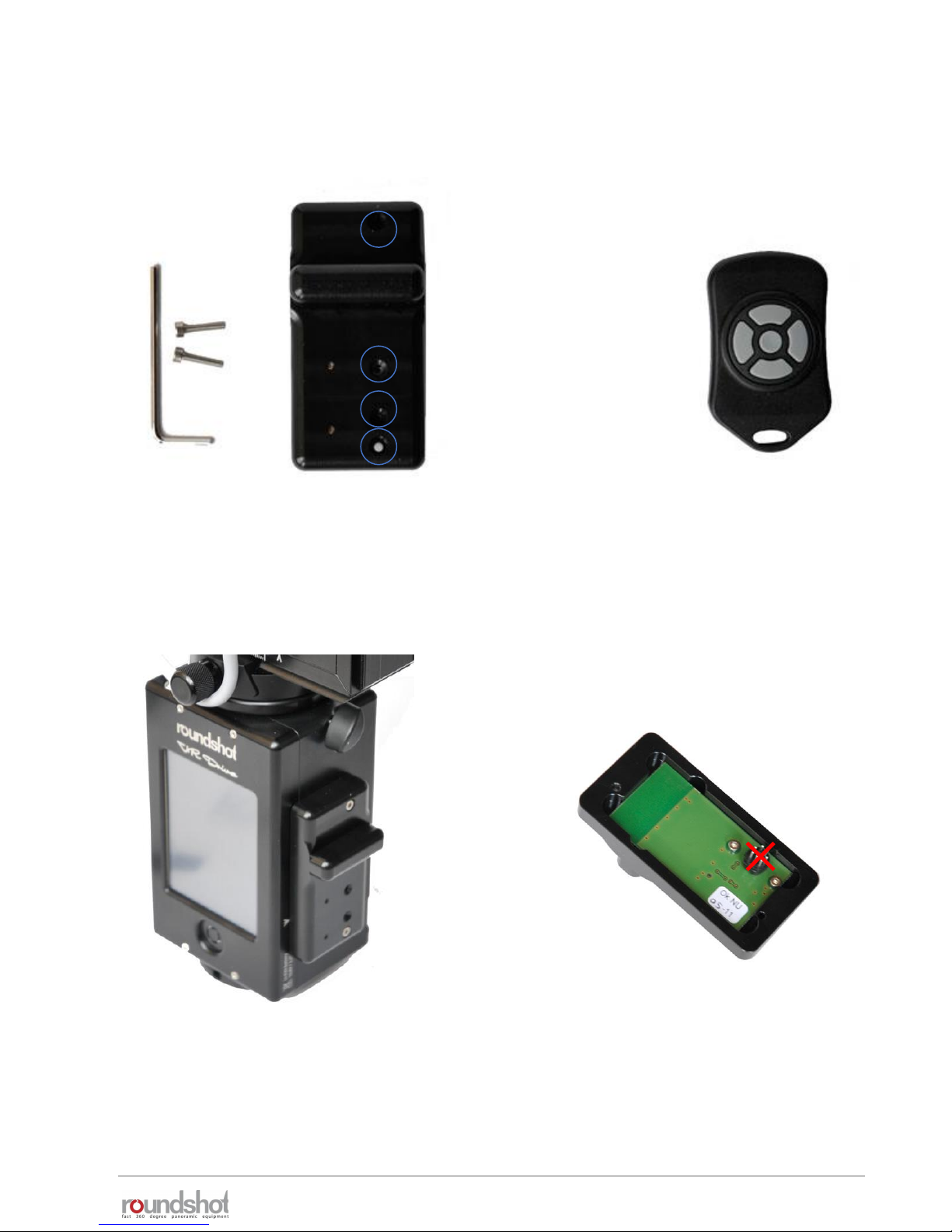
2.1.5 Radio control unit
The radio control unit consists of the following parts:
Allen key with
screws
Radio receiver
(on VR Drive)
Radio sender
(remote)
When separated from VR Drive never
place the radio receiver on the
connector pins as they are fragile.
With the VR Drive delivery the radio control
unit is already attached on the VR Drive.
It does not have to be removed.
Socket for upper screw
Socket for lower screw
Red LED
Sync contact

23/05/2019Roundshot VR Drive Instruction Manual – Firmware Version 2.023 31
2.1.5 Radio control unit (continued)
Attach the radio receiver in the following way:
Insert the radio receiver
pins into the plug
marked with the
antenna symbol:
Insert the lower screw
and attach it with the
allen key.
Insert the upper screw
and attach it with the
allen key.
Now press a sharp item (for example a
pen) into the sync contact in the
middle of the radio receiver.
Then press the “OK” button of the radio
sender. This will synchronise the radio
signal between sender and receiver.

23/05/2019Roundshot VR Drive Instruction Manual – Firmware Version 2.023 32
Once the synchronisation process is complete, the red blinking LED turns off.
The radio sender and receiver are now set up for operation.
left right
down
up
OK
The red LED will turn on when a positioning command is received. The radio control unit
allows to bridge a distance of about 30 metres (100 feet).
Pressing a button continuously will accelerate the positioning speed.
The VR Drive software allows to set certain parameters for the radio control unit in the
settings/general menu:
speed
8/10s
manual movement
In the manual movement menu the
user can set the speed of rotation
and the acceleration preferences
when using the radio control unit.
Please consult the settings menu for further information on these two functions.
Position the VR Drive in the X and Y
dimension using the left/right/up/down
buttons.
“OK” will start the currently active VR Drive
program.
The VR Drive will start a new program from
the actual x-position set with the control
unit.
warning
The battery will
discharge faster when
using this option.
Continue anyway?
manual
movement
remote radio
off
remote radio
on
speed
8/10s
speed
8/10s
acceleration
50%
2.1.5 Radio control unit (continued)

23/05/2019Roundshot VR Drive Instruction Manual – Firmware Version 2.023 33
2.1.6 wifi router for remote control
The Wi-Fi router consists of the following parts:
Connect the Wi-Fi router with the VR
Drive using a short Ethernet cable.
Switch the wifi router on
Finally attach the Wi-Fi On the back of
the VR Drive
HAME router: YoYo router:
ON

23/05/2019Roundshot VR Drive Instruction Manual – Firmware Version 2.023 34
As a first step assign the following fixed IP to the VR Drive in
edit/settings/software/IP:
192.168.169.15 (HAME router) or
192.168.1.15 (YoYo router)
This second step is to connect to the VR Drive Wireless network and
type the password. By default the password is
roundshot
Then you can open any web browser from a smart phone or computer with wifi and type in
the URL : http://192.168.169.15 (HAME) or http://192.168.1.15 (YoYo). You can see now the
same screen content as on the VR Drive main unit and all functionalities are identical.
The default IPs can be changed, for example to adapt them to a different network. To
do this, access the router software by opening a browser window with the IP
192.168.169.2 (HAME) or 192.168.1.2 (YoYo) and change the IP range in the router.
Adapt the IPs in the VR Drive and in the Browser window.
Summary of default IPs:
HAME router YoYo router
Router: 192.168.169.2 192.168.1.2
VR Drive: 192.168.169.15 192.168.1.15
Browser: 192.168.169.15 192.168.1.15
iP
10.0.0.415
192.168.169.15
This VR Drive wifi screen transmission works only with software versions 2.12 or
higher. For older software versions please upgrade the software first.
2.1.6 wifi router for remote control (continued)

23/05/2019Roundshot VR Drive Instruction Manual – Firmware Version 2.023 35
2.2 Setting up the digital camera
Always use manual exposure.
With automatic exposure the
images will be differently
exposed and the VR Drive can
no longer set up the exposure
values for automatic exposure.
Always use manual focusing. Use a fast storage card with
enough capacity.
Set the white balance to a
fixed value. When setting the
white balance to “auto”, every
image will have a different
tone, making the stitching
problematic.
Please make sure that your camera settings correspond to the following:
Set the exposure increments
to 1/3 steps. When selecting
1/2 steps the VR Drive can
no longer set the correct
exposures.
Turn the “Auto rotate” feature
to “off”. When automatically
rotating the images the
stitching will not perform
correctly.
Set the ISO speed setting
increments to 1/3 steps.
When selecting 1/1 steps the
VR Drive can no longer set the
correct exposures.
For bracketing in quality
mode, program the desired
bracketing sequence (number
of images, Evs); for HDR
mode turn it off as the VR
Drive will control the camera

23/05/2019Roundshot VR Drive Instruction Manual – Firmware Version 2.023 36
2.3 Setting up the VR Drive software
Press the VR Drive “on/off” button to start the VR Drive:
Now set the year, month, day and time by using the number keypad.
When several entry fields are available, the active one is highlighted in light blue, the inactive
one in darker blue. Click on an entry field to activate it.
Confirm the entries with the “next” button.
New VR Drives are delivered
with your language, time settings
and camera favourites already set up.
These steps are only necessary after a
factory reset.
1
20
18
30
Deutsch
Italiano
Français
Español
English
language
year
2012
[1970..2100]
month
1
[1..12]
day
20
[1..31]
hours
18
[0..23]
minutes
30
[0..59]
(Press to view settings)
Chinese
Japanese
Português
VR Drive
As a first step, select your language. The options are:
• English
• German
• French
• Italian
• Spanish
• Portuguese
• Russian
• Chinese
• Japanese
Confirm with the “next” button.
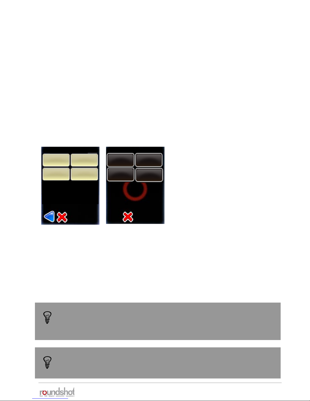
Load the cameras that you will be using with the VR Drive from the
data base, selecting the camera brand/type from the list.
These cameras will be loaded into your personal favourites list
which is required to program the VR Drive.
Click on the button to add more cameras from the database.
Additional cameras can be added later in the “settings” menu. If
your camera is not in the list, it can be added manually to the
database.
23/05/2019Roundshot VR Drive Instruction Manual – Firmware Version 2.023 37
2.3 Setting up the VR Drive software (continued)
The camera type (i.e. the sensor size) is required for automatic calculation of
rows/images in the “quality”, “speed” and “HDR” modes. For the “turntable” and
“video” modes the camera type is used for information only and has no computation
purpose.
When your selection is complete, confirm with the “next” button.
The set-up wizard is now complete.
A first default program in “quality” mode is displayed which uses
the camera data of the first camera in the favourites list and some
default values: “P1”.
“P1” can later be edited, copied, moved or deleted. It is created
only for setting up the VR Drive at this stage.
P1
quality
Nikon D3
focal length : 24 mm
A: 0mm B: 0mm
angle X:360° °
rows : 1
R1°
Duration : 2min 5s
my cameras / page 1
Nikon
my cameras / page 1
my cameras / page 1
Nikon
D3
Canon
5D
Nikon
D3
Canon
5D
PhaseOne
P65+
Nikon
Kodak
Canon Fuji Finepix
SONY DSC Olympus
Panasonic
Leica
If the HDR mode of the VR Drive is active, an HDR compatible camera needs to be
selected in the favourite list. If it is not the case, the VR Drive will ask you to select
one during the set-up process.
x/y

23/05/2019Roundshot VR Drive Instruction Manual – Firmware Version 2.023 38
P1
quality
Nikon D3
focal length : 24 mm
A: 0mm B: 0mm
angle X:360° °
rows : 1
R1°
Duration : 2min 5s
x/y
2.4 Navigation
The VR Drive starts up with the “home menu”:
The “home menu” shows the currently active program. Clicking
on this button will load the program management menu.
active program +
program management
program
down
program
up
program
info / edit
battery
charge +
time
X/Y position,
release, align,
repeat, resume
start program
The arrow buttons “program down” + “program up” allow easy
navigation between existing programs.
In the centre of the screen the main program info parameters
are displayed. Clicking in this section will load the program edit
menu.
The “start” button enables to launch the active program.
The x/y button allows to reposition the starting point, release images in the
x/y space, realign the nodal rail with the y-motor, repeat any image or resume
the program for any x/y position
The battery charge and the current time are displayed with their
respective icons.
When the program sequence is ongoing, this icon will switch to a
red “stop” button.
VR Drive idle VR Drive running
Nikon D3
row : 2/2
position X : 60°
position Y : 45°
image/row : 2/10
Image/total : 12/20
Repeat : 0
Timer : 0
Remaining time : 0min 36s
stop program pause program
The “pause” button will momentarily interrupt the process;
further options are possible (stop, resume)
P1
quality
P1
quality
P1
quality
x/y
Nikon D3
focal length : 24 mm
A: 0mm B: 0mm
angle X:360° °
rows : 1
R1°
Duration : 2min 5s
white balance
Access the “white balance” USB options with the shortcut symbol.

23/05/2019Roundshot VR Drive Instruction Manual – Firmware Version 2.023 39
2.4 Navigation (continued)
Clicking the “active program + program
management” button opens the “program
management” menu.
In this menu new programs can be created
with the “Program Wizard”, existing
programs can be deleted, copied or moved
into a different position. The program can
also be exported on USB key.
More details about this menu are given in
section “Program management”.
Return to the “home menu” by clicking “X”
(cancel) or “home”.
Click on the “x/y” button to manually control
the position of the VR Drive x and y motors.
Select “x/y position” to define the VR Drive 0
point.
Select “x/y release” to freely position the VR
Drive and release the camera (only with
electronic release cable, not with USB cable)
Press “y-align” to realign the nodal rail with the
y-motor, for example after a “transport error”
Use “x-y-repeat” to repeat any image of the
program by selecting its row + position
Use “x-y-resume” to restart a program by
selecting a starting point (row + position)
Move back up to the “home menu” with the
“cancel” button.
new delete
copy move
new delete
copy
move
P1
P1
quality
export P1
Papywizard
export P1
Seitz
x/y
x/y
position
x/y
release
Returns to
“home”
menu
Returns
back one
level
y-align x/y repeat
x/y-resume

23/05/2019Roundshot VR Drive Instruction Manual – Firmware Version 2.023 40
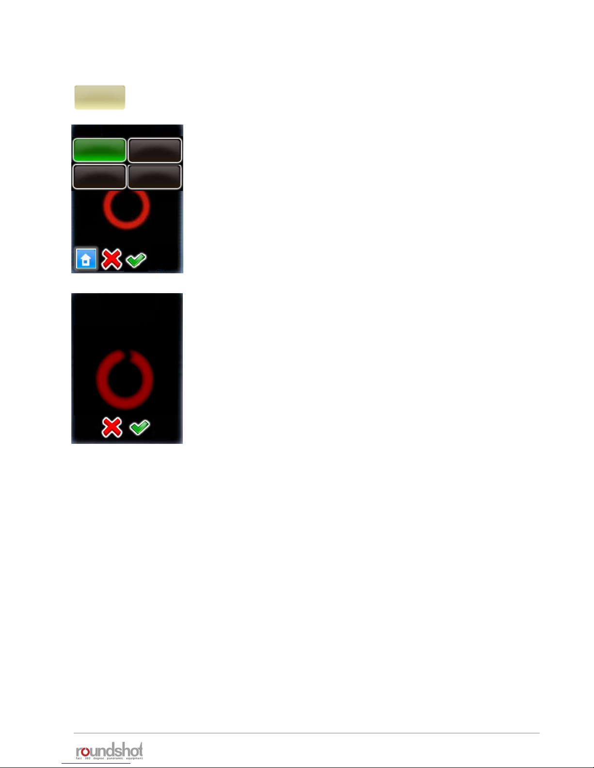
2.4 Navigation (continued)
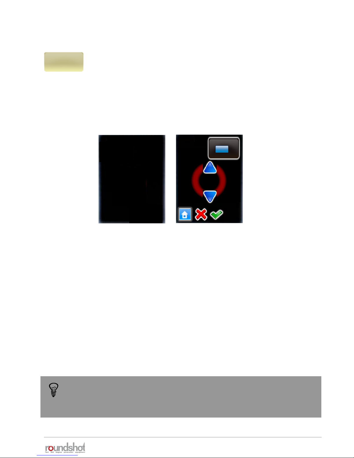
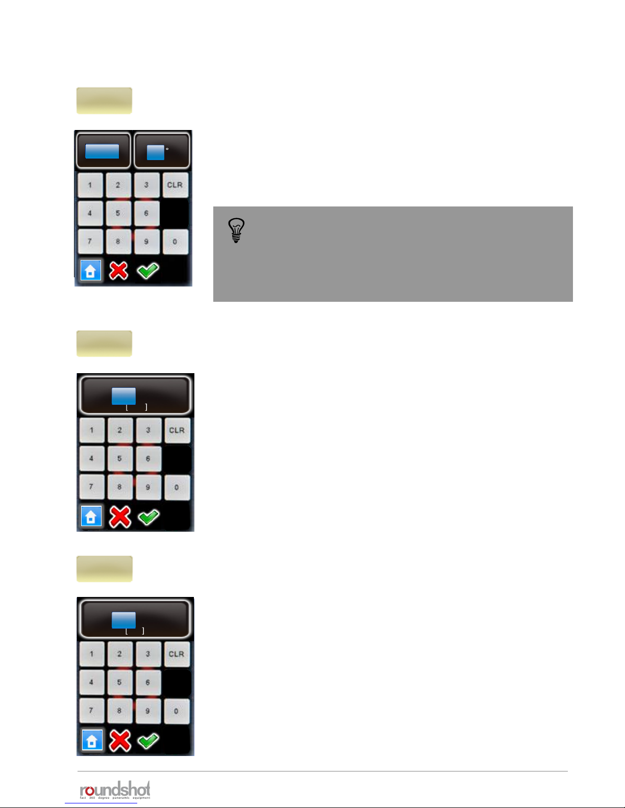
“x/y position” sets the starting or “zero”
position for the VR Drive.
“X” sets the angle in horizontal, “Y” the angle
in vertical direction.
Position the VR Drive to the desired position by
using the arrows up/down/left right.
For example, for image sequences which
always start with the sky (zenith) shot, it is
possible to define the starting position as X= 0°
and Y=90°.
Confirm with the green tick mark or exit by
selecting “home” or “X”.
°
X
°
[1-999.9..999.9]
Y
[-90..+90]
0.0
°
0.0
x/y
position
°
x/y
release
X
°
[1-999.9..999.9]
Y
[-90..+90]
0.0
°
0.0
Rel.
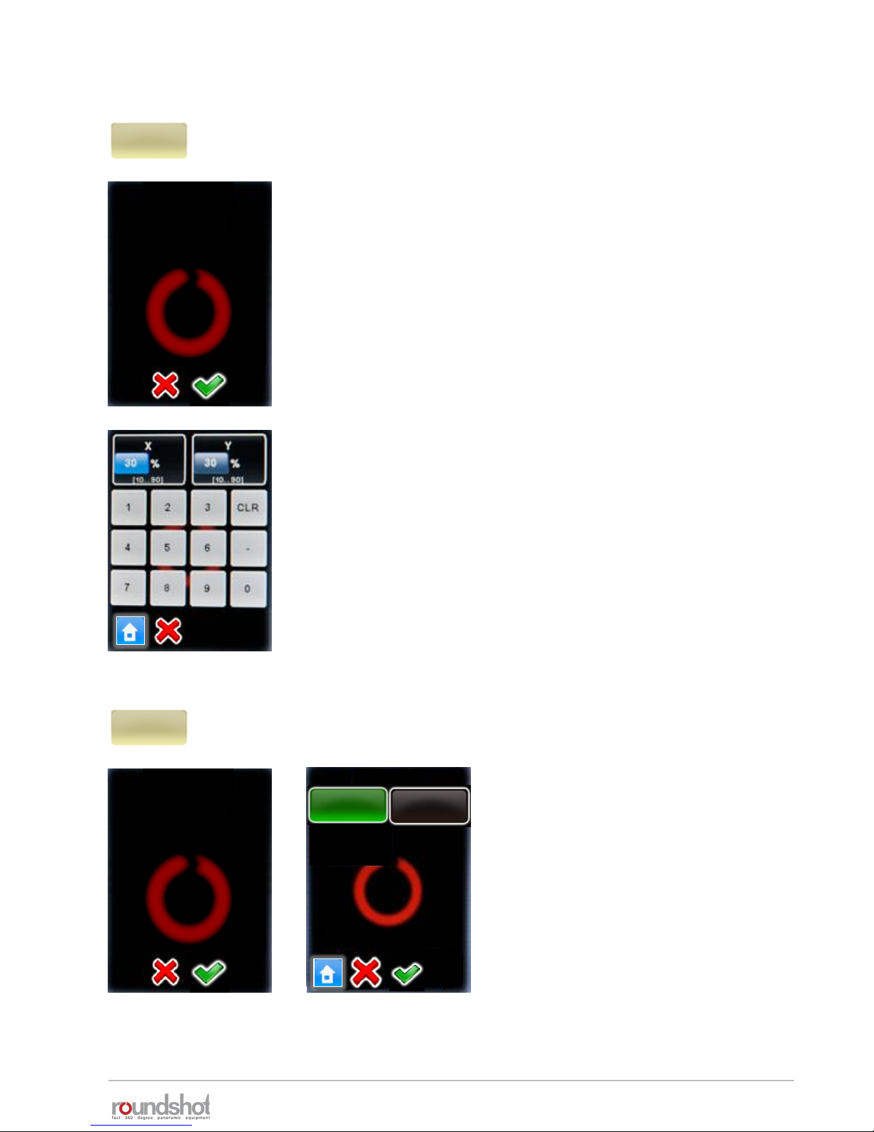
“x/y release” allows to trigger an image from
any position in the x/y space – unrelated to a
VR Drive program.
“X” sets the angle in horizontal, “Y” the angle
in vertical direction.
Release the image by pressing “Rel.” or exit by
selecting “home” or “X”.
Releasing images in the x/y space is only possible with the electronic release cable,
not with the USB cable.
X
°
0.0
[1.0..999.9]
Clicking on the blue degree field
(X or Y) opens a number pad to
enter the desired angle using
numbers and decimals.
0.0
0.0
23/05/2019Roundshot VR Drive Instruction Manual – Firmware Version 2.023 41
2.4 Navigation (continued)
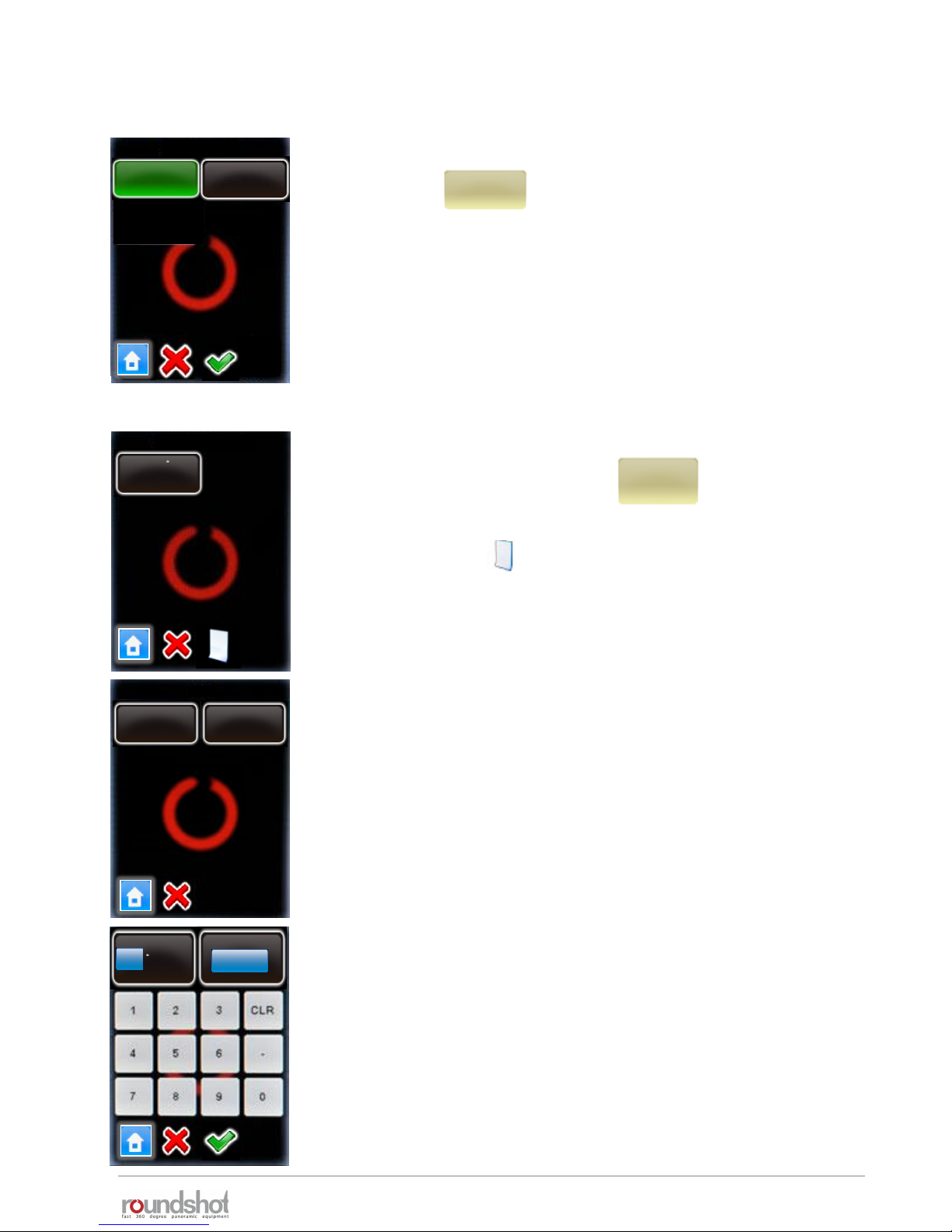
y-align
Nikon
message
Please align the nodal
rail with the y-motor.
Y
[-90..+90]
°
0.0
Click on “y-align” to realign the nodal rail with the y-motor. This may be
necessary in the following cases:
• after a “transport error” when the nodal rail got blocked
• when the y-motor can no longer initialise when starting up
• when the nodal rail no longer aligns with the y-motor when the VR
Drive is off
To follow this procedure, the VR Drive needs to be turned on and the y-
motor connected with the x-y motor cable.
Use the “up” / “down” buttons to align the nodal rail with the y-motor (zero
position).
Turn the VR Drive off and then turn it back on.
Verify if the y-motor initialises and if the nodal rail is moved to the correct
starting position (normally at 0°).
Another and often more effective technique is to perform a hardware realignment of
the nodal rail with the y-motor. For further information please refer to chapter
6.1 – “Hardware realignment of nodal rail with y-motor after “transport error””
23/05/2019Roundshot VR Drive Instruction Manual – Firmware Version 2.023 42
2.4 Navigation (continued)
x/y-
repeat
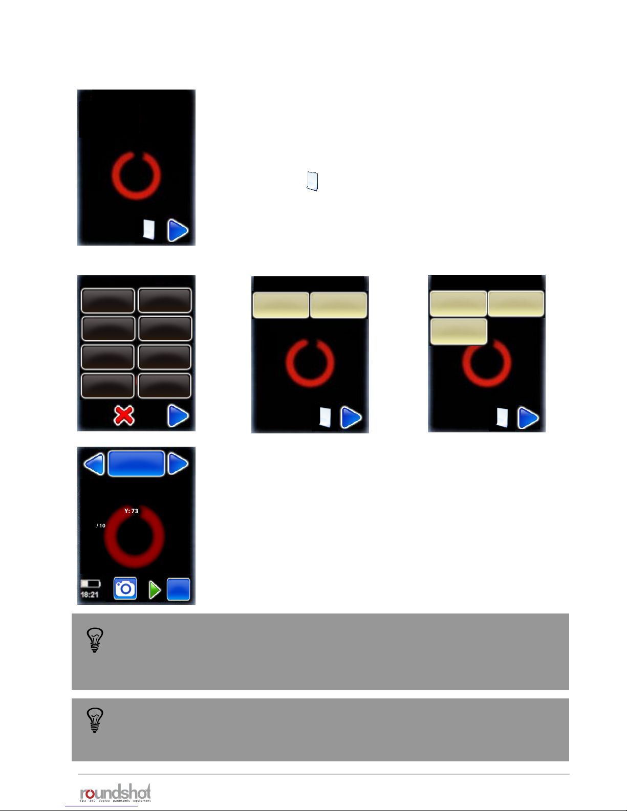
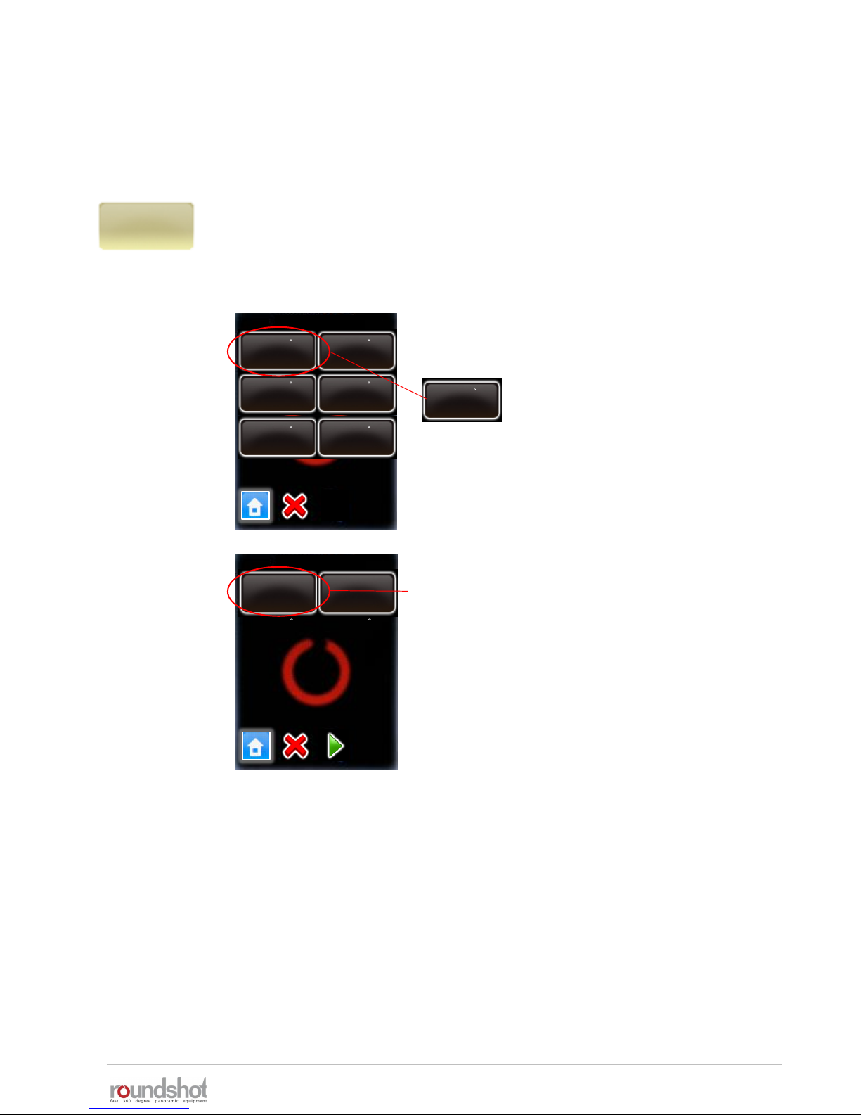
Click on “x/y-repeat” to repeat any image of the program by selecting its row +
position.
This displays the rows of the active program (ie the last program which was
executed. Select the relevant row (elevation):
After completion of a program it may be necessary to repeat individual images or resume a
program from a certain position. This is particularly relevant for gigapixel projects.
repeat position
elev. : 66
images : 30
elev. : 55
images : 30
rows / page 1
elev. : 66
pos. : 30
elev. : 55
pos : 30
elev. : 44
pos : 30
elev. : 33
pos : 30
elev. : 22
pos : 30
elev. : 11
Pos : 30
position repeat
[1…10] [0…0]
Select the relevant row
(elevation), for example:
elev. : 66
pos : 30
For this row, select the position to repeat.
Press “start”.
The VR Drive will now repeat the selected position
of the program.

23/05/2019Roundshot VR Drive Instruction Manual – Firmware Version 2.023 43
2.4 Navigation (continued)
x/y-
resume
Click on “x/y-resume” to restart a program by selecting a starting point (row +
position).
This displays the rows of the active program (ie the last program which was
executed. Select the relevant row (elevation):
repeat position
elev. : 66
images : 30
elev. : 55
images : 30
position repeat
[1…10] [0…0]
For this row, select the position from which the
program should resume.
Press “start”.
The VR Drive will now restart the program from the
selected position.
When using “repeat” and/or “resume” with USB feature “Write IDs”, the Image
Bundler will recognise the repeated/duplicated images and will use these images to
replace previous images released from the same position.
rows / page 1
elev. : 66
pos. : 30
elev. : 55
pos : 30
elev. : 44
pos : 30
elev. : 33
pos : 30
elev. : 22
pos : 30
elev. : 11
Pos : 30
Select the relevant row
(elevation), for example:
elev. : 66
pos : 30

23/05/2019Roundshot VR Drive Instruction Manual – Firmware Version 2.023 44
2.4 Navigation (continued)
Clicking in the middle of the touch screen
opens the “program edit” menu.
In this menu all program parameters can be
changed.
This menu also allows to access the VR
Drive settings menu.
For more information about the “program
edit” menu please refer to chapter 4.
Return to the “home menu” by clicking “X”
(cancel).
mode
quality
info
Nikon
D3
focal length
24 mm
A/B value
0/0mm
angle mode
cylindrical
X
360°
Y
73°
Edit P1 / page 1
Nikon D3
focal length : 24 mm
A: 0mm B: 0mm
angle X:360° °
rows : 1
R1°
Duration : 2min 5s
23/05/2019Roundshot VR Drive Instruction Manual – Firmware Version 2.023 45
2.4 Navigation (continued)
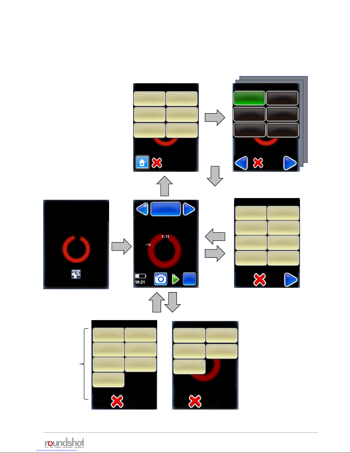
The following is an overview of the VR Drive navigation:
Program management
Home Program edit
Program Wizard
Start-up
new
delete
copy
move
turntable
timelapse
video
P1
quality
mode
speedquality
Edit P1 / page 1
P1
(Press to view settings)
mode
quality
info
Nikon
D3
focal length
24 mm
A/B value
0/ 0mm
angle mode
cylindrical
X
360°
Y
73°
HDR
export P1
Papywizard
export P1
Seitz
x/y
VR Drive
Nikon D3
focal length : 24 mm
A: 0mm B: 0mm
angle X:360° °
rows : 1
R1°
Duration : 2min 5s
x/y menuwhite balance
White balance
Auto
Cloudy
Daylight Tungsten
Fluorescent
Shade
Use camera
settings
Only
accessible if
USB cable is
connected
and set to
“on” in USB
settings
x/y
position
x/y
release
y-align x/y repeat
x/y-resume
23/05/2019Roundshot VR Drive Instruction Manual – Firmware Version 2.023 46
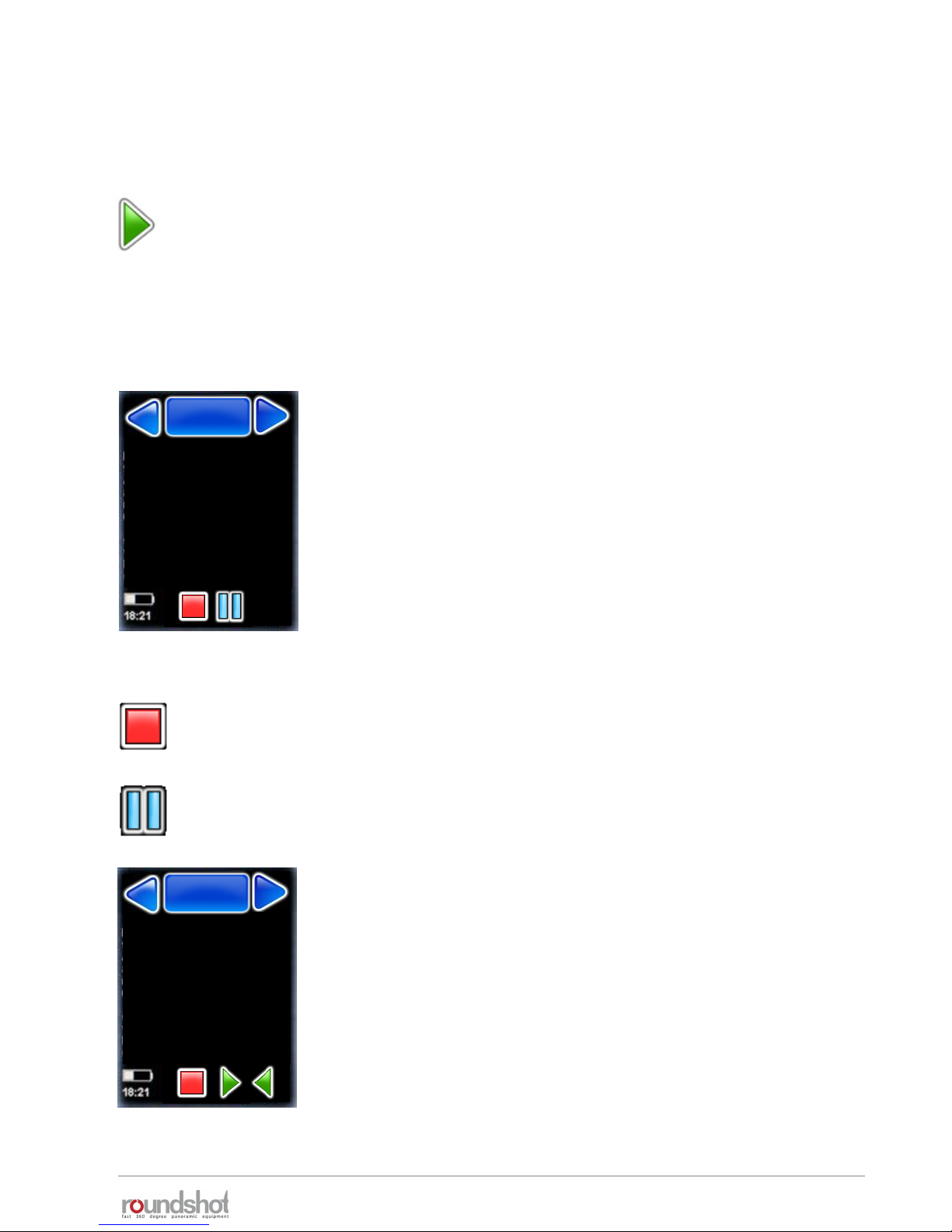
In the “Home” menu click on “start” to launch your first VR Drive image sequence:
The VR Drive will start executing the active program – in this example “P1” in “quality mode”.
In this example it will rotate 360° horizontally to take 10 images spaced at exactly 36°.
The VR Drive stops and releases the camera in every position.
While the VR Drive is running, the touch screen display shows
the progress of image taking:
• Row
• position X
• position Y
• Current image / images in row
• Current image / total number of images
• Number of times the program was repeated
• Timer
• Remaining time
Stop the program any time by pressing the “stop” button.
The VR Drive will return to its initial position and the software
displays the “home” menu with the currently active program.
2.5 Starting/stopping the VR Drive
Pause the program any time by pressing the “pause” button.
The VR Drive will pause at its current position.
Once the program is paused, it is possible to
• Completely stop the image sequence by pressing “stop”
• Resuming the image sequence by pressing “start”
• Returning to any image and by pressing “back” and resuming by
pressing “play”
Nikon D3
row : 2/2
position X : 60°
position Y : 45°
positions/row : 2/10
positions/total : 12/20
Repeat : 0
timer : 0
remaining time : 0min 36s
P1
quality
P1
quality
Nikon D3
row : 2/2
position X : 60°
position Y : 45°
image/row : 2/10
Image/total : 12/20
Repeat : 0
Timer : 0
Remaining time : 0min 36s
P1
quality
P1
quality

23/05/2019Roundshot VR Drive Instruction Manual – Firmware Version 2.023 47
3. Program Management
3.1 Overview
Click the “program management” button.
Besides creating new programs with the
Program Wizard the program management
menu allows to:
• Delete a program
• Copy a program
• Move the ID number of program and the
sequence of programs
• Export a program in Papywizard format.
Used in stitching programs
• Export a program in Seitz format. Used to
back-up program or load it in other units
Clicking the “new” button will launch the Program Wizard to set up new
VR Drive programs using various modes. The program wizard helps to
set-up program parameters in a logical sequence, based on the VR Drive
mode of operation.
See next section for more details about the workflow for each mode.
When clicking the “delete” button the currently active program will be
deleted. This is the program from which the “program management”
menu has been launched, in this example P1. All subsequent programs
(P2, P3, …) will move up and will get new program numbers assigned
(P1, P2, …).
Before deleting the program the program
asks for confirmation.
Cancel with “X”.
Confirm with “OK”.
new delete
copy move
new
delete
copy
move
P1
warning
Do you really want to delete
this program?
P1
quality
new
delete
export P1
Papywizard
export P1
Seitz

23/05/2019Roundshot VR Drive Instruction Manual – Firmware Version 2.023 48
3.1 Overview (continued)
The “copy” command duplicates the currently active program.
This function is helpful when a new program needs to be created that is
very similar to an existing one. After copying the program, simply edit
the relevant parameters in the “program edit” menu.
The “move” command changes the sequence of programs by moving
the currently active program to a new position.
For example, when “P8” is selected and when clicking on “move”, the
program will ask for the new program ID:
After entering the new program number – in
this example “7” – all subsequent programs
will have a number increased by one, so the
previous “P7” will now become “P8”.
id
7
[1..8]
copy
move
export P1
Papywizard
export P1
Seitz
Export a program in Papywizard format. The file will be written on the
connected USB stick provided with the VR Drive. You can use this file with
stitching software to define image positions and their sequence.
Export a program in Seitz format. The file will be written on the
connected USB stick provided with the VR Drive. You can use this file
as a program back-up and load it later in any VR Drive unit.
P7
speed
Nikon D3
focal length : 24 mm
A: 0mm B: 0mm
angle X:360° °
rows : 1
R1°
Duration : 2min 5s
x/y
P8
speed
Nikon D3
focal length : 24 mm
A: 0mm B: 0mm
angle X:360° °
rows : 1
R1°
Duration : 2min 5s
x/y

23/05/2019Roundshot VR Drive Instruction Manual – Firmware Version 2.023 49
3.2 Program Wizard
When creating a new program, the VR Drive will launch the Program Wizard. The program
wizard helps to set-up program parameters in a logical sequence, based on the VR Drive
software mode.
As a first step select the VR Drive mode which you would like to use for
the program.
All active modes are displayed in the list.
The navigation for the following steps in the Wizard is:
• “next” for confirming the choice and moving to the next step, or for
displaying more choices
• “confirm” for confirming the choice and moving to the next step
• “back” for undoing the choice and returning to the previous step
• “X” for cancelling the program and exiting the Program Wizard
Give the new program an ID number.
By default the new program will get the next available number after
the last program.
Confirm with “next”.
speed
turntable
timelapse
video
quality
mode
id
2
[1..2]
HDR
new
Launch the Program Wizard by clicking on “new”.
The Program Wizard will guide you step by step to set up a new VR
Drive program.

23/05/2019Roundshot VR Drive Instruction Manual – Firmware Version 2.023 50
3.2 Program Wizard (continued)
3.2.1 Wizard workflow for quality, speed and HDR modes
“Quality”, “speed” and “HDR” modes, are used to capture panoramic images. The camera is
placed on the nodal rail and the VR Drive releases the camera at predefined position.
The main differences between these 3 modes are:
• “quality” is the basic mode of the VR Drive. In this mode the VR Drive stops and releases the
camera in every position.
• “speed” mode is an optional mode used for fast image capture. In this mode the VR Drive
releases the camera “on the fly” without stopping in every position. No pause after or before
image taking is possible. This image capture mode is only possible in good light conditions
when using fast exposure times on the camera
• “HDR” is an optional mode used for capturing high dynamic range panoramas. It contains a
very advanced bracketing menu and allows the VR Drive to control the exposure time, the
aperture and the ISO/ASA settings of the camera through a connected USB cable.
This section presents the wizard workflow when selecting “quality”, “speed” or “HDR” modes.
These modes were grouped in 1 diagram as they have many common parameters. Specific
parameters for every mode are shown in the following colours:
Common parameters Specific parameters

23/05/2019Roundshot VR Drive Instruction Manual – Firmware Version 2.023 51
3.2.1 Wizard workflow for quality, speed and HDR modes (continued)
Cylindrical Spherical Manual Visual

23/05/2019Roundshot VR Drive Instruction Manual – Firmware Version 2.023 52
3.2.1 Wizard workflow for quality, speed and HDR modes (continued)

23/05/2019 53
3.2.2 Wizard workflow for turntable mode
In “turntable” mode the camera captures images of a rotating object on a turntable
for object movies. the hardware configuration is totally different from any other
mode and therefore the program creation workflow is totally specific.
This section presents the parameter workflow generated by the wizard when
selecting “turntable” mode.
3.2.3 Wizard workflow for “timelapse” and “video” modes
“Video” and “timelapse” modes, are used to move the camera smoothly through a
custom path generating an animated movie.
The main differences between these 2 modes are:
• In “timelapse” mode the VR Drive is used to release the camera and take
pictures every ... seconds or degrees. The images will later be compiled together
and accelerated to get a timelapse movie.
• In “Video” mode the VR Drive is used as a pure motorised arm. No image is
captures and the camera needs to be set to capture a video.
This section presents the parameter workflow generated by the wizard when
selecting “timelapse” or “video” modes. These mode were grouped in 1 diagram as
they have many common parameters. Specific parameters for each mode are shown
in the following colours:
Specific parameters
Roundshot VR Drive Instruction Manual – Firmware Version 2.023

23/05/2019Roundshot VR Drive Instruction Manual – Firmware Version 2.023 54
3.2.3 Wizard workflow for timelapse and video modes (continued)

23/05/2019Roundshot VR Drive Instruction Manual – Firmware Version 2.023 55
4. Program Editing
Edit P1 / page 1
Edit P1 / page 2
Edit P1 / page 3
mode
quality
info
Nikon
D3
focal length
24 mm
A/B value
0mm
0mm
angle mode
cylindrical
X
360°
Y
73°
overlap
30%
30%
orientation
portrait
image number
variable
sequence
zig.-zag top
down
speed
6s
10s
pause position
0s
0s
release time
0.1 s
timer
0s
repeat
0
0°
acceleration
100%
bracketing
1
manual
off
orientation
CCW
4.1 Editing in quality, speed and turntable modes
Click on “mode” to change the VR Drive mode.
It is possible to switch from “Quality” to “Speed” mode and
vice-versa.
Changing to “Speed” mode does not change the calculation of
rows (elevation and images) or any other program parameters.
The only difference is that the following parameters will no
longer be accessible in “speed” mode and will therefore be
deactivated:
The “Turntable” mode is an entirely different application. The number of images are not
calculated and therefore this mode has different variables. The same is true for the “Video”,
“timelapse” and “HDR” mode.
This is why it is not possible to switch to “Turntable”, “timelapse”, “Video”, or “HDR” mode
from “Quality” mode.
• Pause before / after image taking
• Acceleration
• Mirror prerelease
• Manual image release
• Bracketing
mode
quality
rows
mirror rel.
0s
speed
turntable
timelapse
video
quality
mode
HDR
pause image
0s
0s
Edit P1 / page 4
lens type
No fisheye
back to start
off
Once a new program is created using the Wizard, it is accessible from the program list in the home
menu.
By accessing the “program edit” menu it is possible to edit any of the program parameters
individually.
In this section you can find a detailed description of every editable program parameter as well as all
the VR Drives predefined settings.
Click in the centre of the touch screen to open the “program edit” menu.
USB settings
settings
floor patch
off
auto exposure
settings

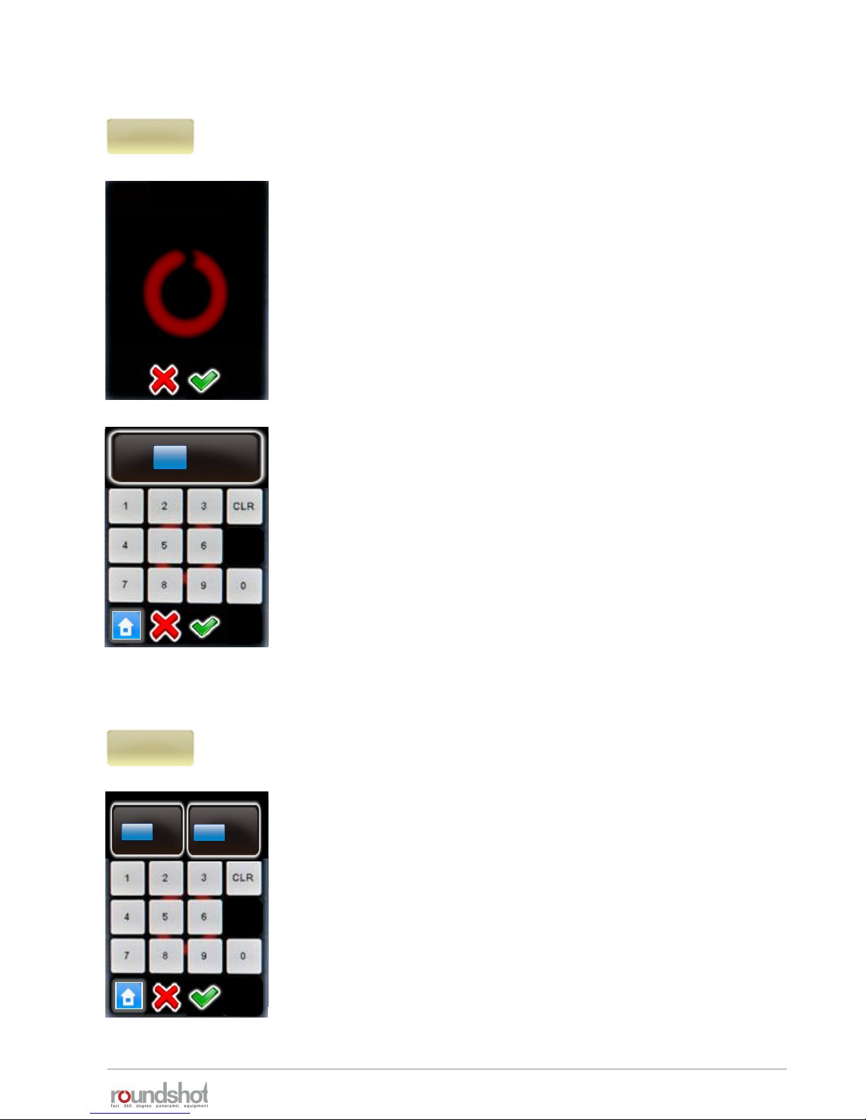
23/05/2019Roundshot VR Drive Instruction Manual – Firmware Version 2.023 56
Click on “text” to change the label of the program.
Enter an alphanumeric/numeric text using the electronic
keyboard.
It may be helpful to use a pen or other sharp item when using
the keyboard.
Confirm with “OK”.
Click on “camera” to change camera brand/type.
As the sensor size is different from camera to camera, changing
the camera will lead to an automatic recalculation of rows
(elevation/images) for the program.
In angle mode “cylindrical” and “spherical” the existing rows will
be overwritten. In angle mode “manual” the change of camera
has no consequences. Here the rows must be edited manually.
Select the camera that you would like to use for the new
program from your favourites list.
If the desired camera is not in the list, click on to access the
full camera database. Select the camera to be added in the
favourite list.
Confirm the choice of camera with “OK”.
The rows (elevation, number of images) will now be
automatically recalculated.
info
Cylindrical 1
info
my cameras / page 1
Nikon
D3
Canon
5D
PhaseOne
P65+
Nikon
D3
4.1 Editing in quality, speed and turntable modes (continued)
23/05/2019Roundshot VR Drive Instruction Manual – Firmware Version 2.023 57
Click on “focal length” to change the focal length of the lens
used for the program.
Changing the focal length will lead to an automatic recalculation
of rows (elevation/images) in angle modes “cylindrical”,
“spherical” or “visual”. In angle mode “manual” the change of
camera has no consequences. Here the rows must be edited
manually.
Continue with “OK” or cancel with “X”.
Enter the focal length of the camera lens.
This value must correspond with the exact setting on the lens.
It is used – together with the camera sensor size and the vertical
field of view – to automatically calculate the number of rows and
images.
Confirm with “OK” or cancel with “X”.
In angle mode “cylindrical” and “spherical” the existing rows will
be overwritten. In angle mode “manual” the change of camera
has no consequences. Here the rows must be edited manually.
Click on “A/B value” to change the rotation and nodal point
values for the program.
Please make sure that these values are correct. When setting the
camera at wrong rotation or nodal points the stitching of images
will not work.
Confirm with “OK” or cancel with “X”.
focal length
24mm
focal length
By changing this value you
will overwrite the rows.
Continue anyway?
focal length
[0..999]
24
mm
A/B value
0/0mm
A
mm
[1..999]
B
mm
[1..999]
0
0
4.1 Editing in quality, speed and turntable modes (continued)
23/05/2019Roundshot VR Drive Instruction Manual – Firmware Version 2.023 58
Click on “angle mode” to change the way the rows (elevation,
number of images) are calculated.
The options are:
• cylindrical
• spherical
• Manual
• Visual
Changing the angle mode will lead to an automatic recalculation of
rows (elevation/images) for the program.
Choose the new “angle mode” by clicking on the button.
The following angle mode modifications are possible:
• from cylindrical to spherical (computes a sphere)
• from spherical to cylindrical (computes one row with vertical FOV
of chosen lens)
• from cylindrical to manual (requires manual programming of
rows)
• from spherical to manual (requires manual programming of rows)
The transition from manual or visual to cylindrical or spherical is
not possible.
Continue with “OK” or cancel with “X”.
In angle mode “cylindrical” and “spherical” the existing rows will be
overwritten. In angle mode “manual” the change of camera has no
consequences. Here the rows must be edited manually.
angle mode
cylindrical
angle mode
spherical
visual
manual
cylindrical
change angle
By changing this value
you will overwrite the
rows. Continue anyway?
4.1 Editing in quality, speed and turntable modes (continued)

23/05/2019Roundshot VR Drive Instruction Manual – Firmware Version 2.023 59
Click on “X” or “Y” to change the horizontal or vertical angle for the
program.
Changing the angle will lead to an automatic recalculation of rows
(elevation/images) or number of images per row for the program.
Continue with “OK” or cancel with “X”.
Enter the “X” angle (horizontal angle).
Confirm with “OK” or cancel with “X”.
The number of images per row will now be automatically
recalculated.
Enter the “Y” angle (vertical angle).
Confirm with “OK” or cancel with “X”.
The rows (elevation, number of images) will now be automatically
recalculated.
X
360°
Y
73°
change angle
By changing this value
you will overwrite the
rows. Continue anyway?
X
°
360
[1.0..999.9]
Y
°
73
[1.0..180.0]
4.1 Editing in quality, speed and turntable modes (continued)
23/05/2019Roundshot VR Drive Instruction Manual – Firmware Version 2.023 60
Click on “overlap” to change the % overlap between images
horizontally and vertically.
Changing the overlap will lead to an automatic recalculation of
rows (elevation/images) or number of images per row for the
program.
Continue with “OK” or cancel with “X”.
Enter the “X overlap” (horizontal overlap).
Confirm with “OK” or cancel with “X”.
The number of images per row will now be automatically
recalculated.
Enter the “Y overlap” (vertical overlap).
Confirm with “OK” or cancel with “X”.
The rows (elevation, number of images) will now be automatically
recalculated.
change overlap
By changing this value
you will overwrite the
rows. Continue anyway?
overlap
30/30%
orientation
By changing this value
you will overwrite the
rows. Continue anyway?
orientation
portrait
orientation
landscape
portrait
Click on “orientation” to change the way
the camera is attached on the VR Drive.
Changing the camera orientation will lead
to an automatic recalculation of rows
(elevation/images) or number of images
per row for the program.
Continue with “OK” or cancel with “X”.
4.1 Editing in quality, speed and turntable modes (continued)
23/05/2019Roundshot VR Drive Instruction Manual – Firmware Version 2.023 61
Image number
variable
Image number
fix
variable
Click on “image number” to change the way the number of images per
row is calculated. This option is only available when using cylindrical
angle mode.
• Select “variable” to allow every row to have a specific number of
images. this option generate the minimum number of images.
• Select fix to have the same number of images for all rows. Select this
option when using vertical sequences to optimize VR Drive
movements. However the number of images will be higher.
Continue with “OK” or cancel with “X”.
Click on “rows” to create new rows, delete existing rows or edit a
row (elevation, number of images).
By changing the rows any previous automatic computation will be
overwritten.
By clicking on the button additional rows/images can be
added to the program
Select the row by clicking on it.
Select “edit” or “delete”.
When creating a new row or editing an existing one, enter the
desired elevation in degrees and the number of images per row.
Confirm with “OK” or cancel with “X”.
rows
rows / page 1
elev. : 1
images : 10
P2P2
edit
delete
elev.
1
images
10
[-90..90]
[1..9999]
4.1 Editing in quality, speed and turntable modes (continued)
23/05/2019Roundshot VR Drive Instruction Manual – Firmware Version 2.023 62
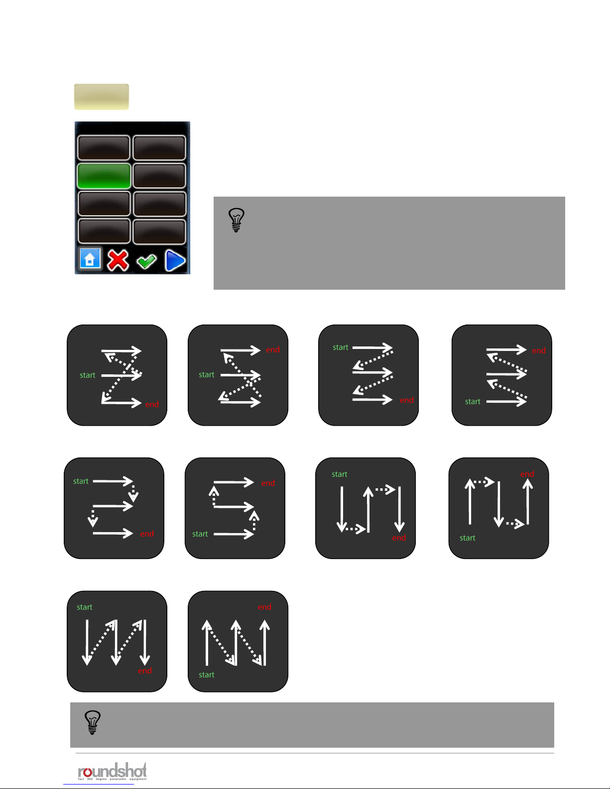
Click on “sequence” to change the order in which the rows of
images are captured.
Select the new sequence.
Click on “next” to see more sequences.
Confirm with “OK” or cancel with “X”.
zig-zag center up: zig-zag center down: zig-zag top down: zig-zag bottom up:
vertical top down: vertical bottom up:
sequence
zig-zag center
up
zig-zag center
down
zig-zag bottom
up
snake h top
down
snake h
bottom up
snake v top
down
snake v
bottom up
zig-zag top
down
sequence
zig-zag
The sequence of image taking is only relevant for multi-row
panoramas.
It is designed for those situations where the light changes
quickly (for example at sunrise/sunset) or where there is
movement in the scene.
If none of the 10 sequence presets are ideal, use the “manual” angle mode. In this
mode the rows (elevation in °, number of images) and their sequence can be
customised.
snake h top down: snake h bottom up: snake v top down: snake v bottom up:
4.1 Editing in quality, speed and turntable modes (continued)

23/05/2019Roundshot VR Drive Instruction Manual – Firmware Version 2.023 63
Click on “speed” to change the rotation speed for the VR Drive.
Enter the “X speed” for the horizontal movement.
Enter the “Y speed” for the vertical movement.
The minimum speeds are:
• X: 6 seconds (for a horizontal movement of 360°)
• Y: 10 seconds (for a vertical movement of 180°)
Confirm with “OK” or cancel with “X”.
Click on “release time” to change the duration of the release signal
given by the VR Drive to the camera for every image.
The release time corresponds to the duration of the release signal
given from the VR Drive to the camera.
Varying the release time is required to optimise the operation of
the VR Drive in “speed” mode.
Confirm with “OK” or cancel with “X”.
Click on “pause position” to change the pause at the start or at the
end of the capture sequence at 1 position.
The pause start/end position is used to minimise potential
vibrations caused by motor movements.
Click on “pause image” to change the pause before or after every
image.
The pause before/after image is only available when more than one
image is taken at every position. It is used for example with long
exposure times.
Confirm with “OK” or cancel with “X”.
X
6
Y
10
[6..9999]
[8..9999]
release time
0.1s
Pause position
0 s
0 s
release time
0.1..0.9
0.1 s
speed
6s
elev.
0
images
7
[-90..90]
[1..9999]
pause before
0
s
pause after
0
[0.0..999.9]
[0.0..999.9]
s
Pause image
0 s
0 s
4.1 Editing in quality, speed and turntable modes (continued)
23/05/2019Roundshot VR Drive Instruction Manual – Firmware Version 2.023 64
Click on “repeat” to program a repetition of the program.
Enter the number of repetitions.
Enter the Offset angle. This will move the starting point of the next
repetition in the horizontal direction (X-motor)
Confirm with “OK” or cancel with “X”.
Click on “timer” to program a time delay before the program is
launched.
Enter the time delay. This delay is inserted at the beginning of a
program (sequence).
Confirm with “OK” or cancel with “X”.
Click on “acceleration” to define the speed adaptation when the
VR Drive starts and stops.
The acceleration value is computed when setting up the program in
the Program Wizard and depends on the focal length:
• <20mm: 100%
• 20mm to 50mm: 50%
• >50mm: 20%
The acceleration values range from 1% (slow speed adaptation) to
100% (fast speed adaptation).
For programs with heavy cameras and bulky lenses (for example:
gigapixel projects) lower the acceleration to avoid vibrations.
Confirm with “OK” or cancel with “X”.
timer
0..9999
0 s
acceleration
1..100
100
%
repeat
0
0°
timer
0s
acceleration
100%
When repeat is set to 2, the program will be done 3 times
in total (the original program + 2 repetitions)
If the target is to have overall 2 times the program please
set the repeat value to 1.
4.1 Editing in quality, speed and turntable modes (continued)
repeat
0
0
[0..9999]
[-180..180]
offset

23/05/2019Roundshot VR Drive Instruction Manual – Firmware Version 2.023 65
Click on “bracketing” to program multi-exposures per position.
Bracketing “1” means no multi-exposures – only one image will be
released per position.
With bracketing “3”, “5”, “7”, “9”, “11” and “13” several images are
released per position.
The bracketing values (number of images, bracketing range in f-
stops, type of bracketing) need to be set in the camera software.
Make sure that the number of images set in the camera software
and in the VR Drive software match.
Confirm with “OK” or cancel with “X”.
“Special bracketing” is used with cameras which allow the release
and bracketing of several images in multi-shot mode.
Set the bracketing and multi-shot feature on the camera.
Enter the total duration of the “multi-shot” in the VR Drive
software. The VR Drive will then give a longer release signal to the
camera for the multi-shots.
Confirm with “OK” or cancel with “X”.
Click on “manual” to activate or deactivate the manual release of
the image in every position:
• Manual “on”: requires releasing every picture manually
• Manual “off”: releases the images automatically
manual
on
manual
off
bracketing
1
elev.
0
images
7
[-90..90]
[1..9999]
bracketing
5
3
7
9
11
13
special
1
elev.
0
images
7
[-90..90]
[1..9999]
bracketing
5
3
7
9
11
13
special
1
The bracketing of the camera in “quality mode” is limited to +/- 2 EVs (f-stops). For 32-
bit HDR photography this is insufficient. With the VR Drive “HDR mode” it is possible to
eliminate this limitation. In the “HDR mode” the VR Drive controls the camera software
directly, allowing much larger bracketing steps and a larger dynamic range.
HDR bracketing
[0..9999]
2 s
4.1 Editing in quality, speed and turntable modes (continued)

23/05/2019Roundshot VR Drive Instruction Manual – Firmware Version 2.023 66
Click on “mirror release” to activate the release of the camera
mirror before image taking.
Enter the duration of mirror release.
Confirm with “OK” or cancel with “X”.
Click on “orientation” to change the direction in which the VR Drive
turns.
• Orientation“CW”: rotates clockwise
• Orientation“CCW”: rotates anti-clockwise
double
Release
mirror release
Now choose whether to give a single or double mirror release
signal.
Typically, Nikon cameras require a single, Canon a double signal.
Confirm with “OK” or cancel with “X”.
mirror rel..
0s
elev.
0
images
7
[-90..90]
[1..9999]
mirror rel.
s
0
[0.0..999.9]
single
Release
orientation
CW
orientation
CCW
lens type
By changing this value
you will overwrite the
rows. Continue anyway?
Lens type
No fisheye
Lens type
No fisheye
Fisheye
To use “mirror release” in HDR mode, it is necessary to release the images with the
electronic release cable and not with USB. Please use the USB cable for camera
control functions (HDR bracketing) only.
4.1 Editing in quality, speed and turntable modes (continued)

23/05/2019Roundshot VR Drive Instruction Manual – Firmware Version 2.023 67
When “floor patch” is set to “on”, the VR Drive will display a
message at the end of the program to move the tripod by
approximately 1m sideways.
After pressing “play”, the VR Drive will then capture one
(bracketing=1) or several (bracketing>1 or HDR mode) images at a
predefined angle.
The floor patch feature is only available for quality + HDR modes for
panoramas with angle mode “spherical”.
Confirm with “OK” or cancel with “X”.
When using a horizontal sequence (such as “zig-zac”), the “back to
start” option forces the x-motor to return back to its starting
position (for example: by 360°).
This feature can be useful when external devices (for example a
charger unit) are connected to the VR Drive x-motor to unwind any
cables.
Confirm with “OK” or cancel with “X”.
floor patch
-45.0°
elev.
0
images
7
[-90..90]
[1..9999]
floor patch angle
°
-45.0
[-90.0 .. 90.0]
4.1 Editing in quality, speed and turntable modes (continued)
back to start
on

23/05/2019Roundshot VR Drive Instruction Manual – Firmware Version 2.023 68
4.2 Editing in timelapse and video modes
The image release mode parameter allows to select the way the
images will be released in timelapse mode. The choices are:
• Seconds to release the images every… seconds
• Position to release the images every… degrees
X
0
Y
0
[-999.9..999.9]
[-90.0..90.0]
start
0/0°
Image release
mode
seconds
Image release
mode
position
Please note that the “Hardware” and “image release mode” cannot be edited in this menu
as these variables creates an entirely different image release or movement behavior. It is
possible to select the correct value during the creation of a new program in the wizard.
Click on “start” to change initial position from which the VR Drive
launches the video sweep.
By default, the VR Drive starts from 0° / 0° to reach the first point
defined in the “Program Wizard”.
Enter the “X” and “Y” coordinates of the starting point.
Confirm with “OK”.
The Hardware parameter allows to define the type of hardware
used to generate the time-lapse or the video sequence. As
shown in the “Setting up the VR Drive hardware” section the
choices are:
• 360: when using the standard VR Drive with X and Y motor
• Linear: when the VR Drive is attached to the linear rail
hardware. In this configuration the X motor is used to rotate
the camera and the Y motor to slide along the rails
• Dolly: when the VR Drive is attached to the special dolly. In this
configuration the X motor is used to change direction and the Y
motor to rotate the front wheel.
Hardware
360
Hardware
linear
Hardware
dolly
The parameters for the video and timelapse modes are very specific. This is why they cannot be
changed into another mode (such as quality, speed or turntable).
In the edit menu, the parameters shared with quality mode can be modified in the same way. For
example, it is possible to change the program info text, the camera, the focal length…
In addition, the video and timelapse modes allows to edit specific parameters. For example the
starting position, points for the video sweep… only these specific parameters are described in this
section.

4.2 Editing in timelapse and video modes (continued)
Click on “point” to edit the points through which the video
sweep navigates.
By clicking on the button additional point can be added to
the program
Click on a point to edit or delete it.
P6
Delete a point by clicking “delete”.
Edit a point by clicking “edit”.
The parameter of a point are displayed and can be edited one by one.
• Point coordinates (X/Y) (degrees or cm depending on hardware)
• Duration
• Acceleration
• Pause
• Image every … degrees (or seconds) (only for timelapse mode)
points / page 1
point 1
X-45°\ Y45°
point 2
X-88°\ Y13°
P6
edit
delete
point
points
duration
30
point
-45/45°
pause
1
acceleration
50
Image
every …
degrees
Click on “point” to change its X/Y coordinates.
Use the arrow keys to navigate.
The X and Y coordinate can be either degrees or centimeters
depending on the hardware configuration (360, linear or dolly)
Confirm with “OK”.
edit
delete
X
°
-45.0
[-999.9..999.9]
Y
°
45.0
23/05/2019Roundshot VR Drive Instruction Manual – Firmware Version 2.023 69

23/05/2019Roundshot VR Drive Instruction Manual – Firmware Version 2.023 70
point
acceleration
50
pause
1
speed
30
point
-45/45°
images
0
edit
delete
X
°
0.0
[-999.9..999.9]
duration
30
[8..9999]
pause
1
[0.1...3600.0]
acceleration
50
[0.1..3600.0]
Click on “duration” to change the time duration of the video
sweep from the previous point to the current one.
Confirm with “OK”.
Click on “acceleration” to adjust the velocity at which the speed
is adjusted.
Select a low value for slow speed adjustment, a high value for
fast adjustment.
Confirm with “OK”.
Click on “pause” to set a pause (in seconds) at the point.
Confirm with “OK”.
One image every … degrees
5
[1..9999]
In “timelapse” mode the “image release mode” parameter
(seconds or position) sets the VR Drive to release one image every
few seconds or degrees.
Enter the number of seconds or degrees at which one image is to
be released.
Make sure that the camera has enough time to create the images.
Confirm with “OK”.
4.2 Editing in timelapse and video modes (continued)

23/05/2019Roundshot VR Drive Instruction Manual – Firmware Version 2.023 71
4.3 Editing in HDR mode
Click on “mode HDR” to access all HDR parameters for editing.
mode
HDR
Edit HDR
number of
pictures
exposure
reference
sequence
fast-slow
Aperture
steps
HDR steps
aperture
compensation
off
exposure
reference
By changing this value
you will overwrite the
HDR steps. Continue
anyway?
aperture steps
average exposure
move
edit
All parameters previously set up in the HDR Program Wizard can
be accessed and modified.
Click “exposure reference” to move or edit the
reference exposure speed of the HDR table.
Select “move” or “edit”.
Confirm with “OK”.
The parameters for the “HDR” mode are very specific. This is why it cannot be changed into another
mode (such as “quality”, “speed” or “turntable”).
In the edit menu, some parameters shared with “quality” mode can be modified in the same way.
For example, it is possible to change the program info text, the camera, the focal length…
In addition, the “HDR” mode allows to edit specific parameters linked to the bracketing sequence to
be taken at each position. For example the exposure reference, the aperture steps… only these
specific parameters are described in this section.
The bracketing of the camera in “quality mode” is limited to +/- 2 EVs (f-stops). For
32-bit HDR photography this is insufficient. With the VR Drive “HDR mode” it is
possible to eliminate this limitation. In the “HDR mode” the VR Drive controls the
camera software directly, allowing much larger bracketing steps and a larger dynamic
range.

23/05/2019Roundshot VR Drive Instruction Manual – Firmware Version 2.023 72
4.3 Editing in HDR mode (continued)
Click on “move”.
The function “shift average exposure” will shift the
center exposure of the HDR table.
The values are given in aperture (f-stops).
Confirm with “OK”.
move
edit
shift average exposure
-10..8
0
exposure reference type
fastest
slowest
average
Click on “edit”.
Select the exposure reference type
to be defined (fastest, slowest or
average)
Select the exposure speed, on
which the HDR bracketing will be
built.
Confirm with “OK”.
number of
pictures
By changing this value
you will overwrite the
HDR steps. Continue
anyway?
aperture steps
number of pictures
1..94
5
Click on “number of pictures”.
Enter the number of bracketed
images per position.
For example, with 5 images the VR
Drive will release one image at
average exposure speed, 2
underexposed and 2 overexposed
images.
Confirm with “OK”.
Ø exposure speed / page 4
1/8s
1/10s
1/15s
1/20s
1/25s
1/30s
1/40s
1/13
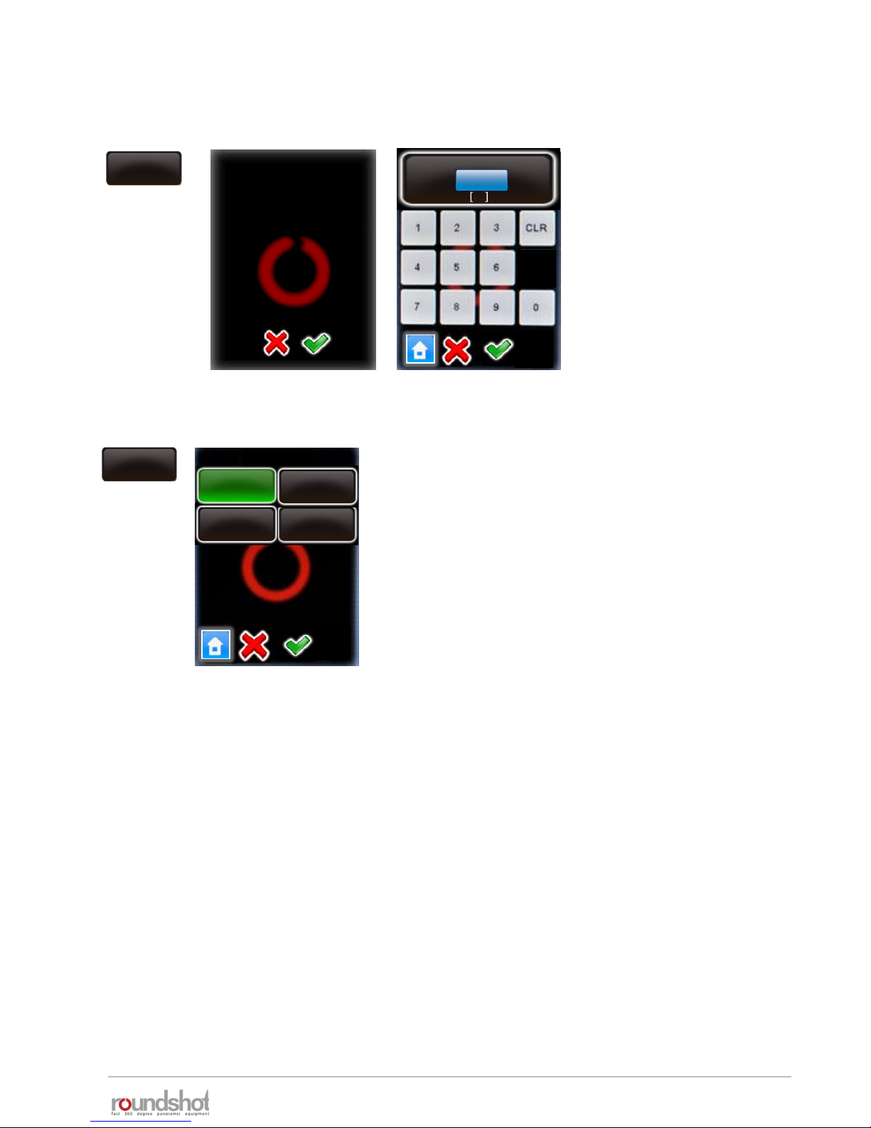
23/05/2019Roundshot VR Drive Instruction Manual – Firmware Version 2.023 73
4.3 Editing in HDR mode (continued)
Click on “aperture steps”.
Enter the aperture steps
between images.
This corresponds to the
difference in f-stops from one
bracketing step to the next.
For example, with 3 aperture
steps there will be a 3 f-stop
difference for every image.
Confirm with “OK”.
By changing this value
you will overwrite the
HDR steps. Continue
anyway?
aperture steps
aperture steps
1..5
3
aperture
steps
sequence
slow - fast
middle – slow -
fast
middle – fast -
slow
fast - slow
sequence
Click on “sequence”.
The sequence function defines in which order the
images are released.
For example, “middle-fast-slow” will first release the
image with average exposure, then the fastest, 2
nd
fastest, etc., then the slowest, 2ndslowest etc.
Confirm with “OK”.
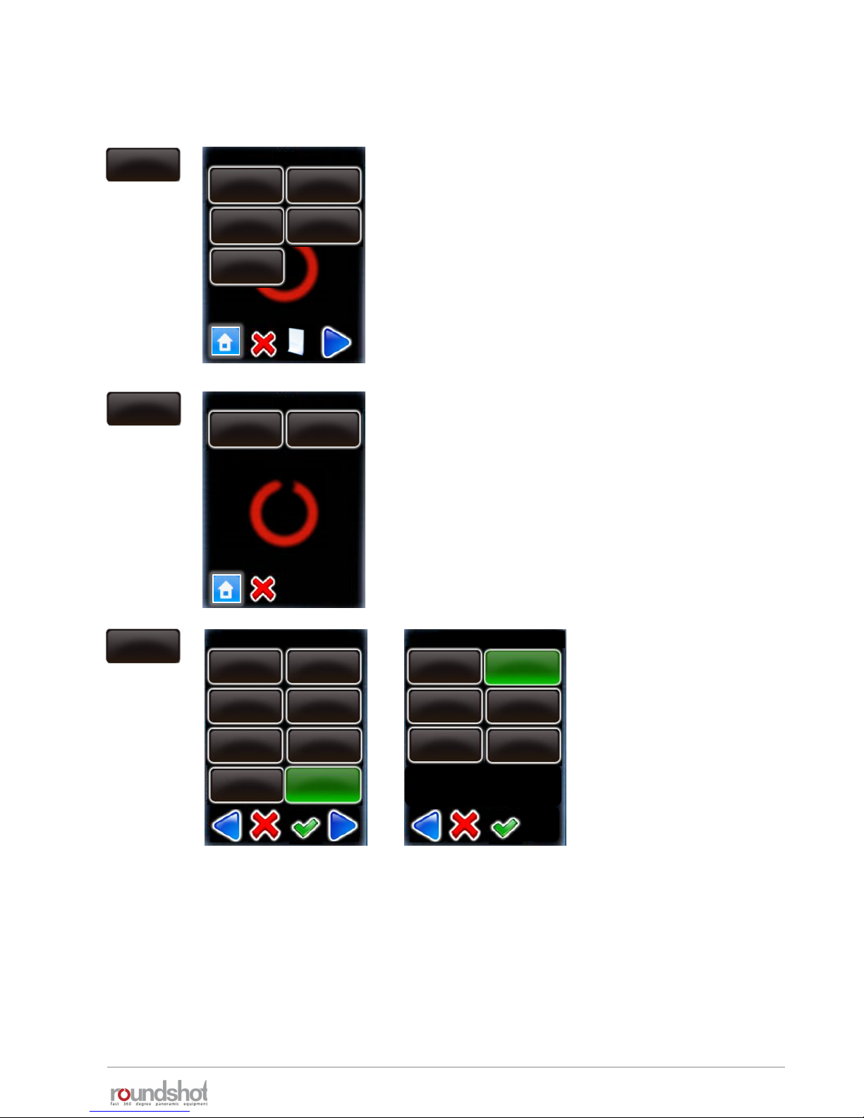
23/05/2019Roundshot VR Drive Instruction Manual – Firmware Version 2.023 74
Click on “HDR steps”.
The table displays the exposure speed, aperture
(f-stop) and ISO/ASA for every image released in
the bracketing sequence.
Access any HDR step by clicking on it.
HDR steps
Delete any HDR step by pressing “delete”.
Edit any HDR step by selecting “edit”.
HDR steps / page 1
exp.: 2s
aperture: f8
ISO/ASA: 100
exp.: 1/4s
aperture: f8
ISO/ASA:100
exp.: 1/250s
aperture: f8
ISO/ASA: 100
exp.: 1/30s
aperture: f8
ISO/ASA: 100
exp.: 1/2000s
aperture: f8
ISO/ASA: 100
P9
edit
delete
exp.: 2s
aperture: f8
ISO/ASA: 100
Ø exposure speed / page 2
5s
4s
2.5s
1.6s
2s
3.2s
1.3s
1s
Select a new exposure speed
in the list of possible values.
Confirm with “OK”.
Select a new aperture (fstop) in the list.
Confirm with “OK”.
aperture / page 1
f 4
f 5.6
f 11
f 16
f 22
f 8
edit
4.3 Editing in HDR mode (continued)

23/05/2019Roundshot VR Drive Instruction Manual – Firmware Version 2.023 75
Click on “aperture compensation”.
Setting this option to “off” will keep the f-stop for
all images identical.
With aperture compensation set to “on”, the VR
Drive will compensate with f-stops in case an
exposure limit is reached (exposure slower than,
for example, 30s, or faster than 1/8000s).
Confirm with “OK”.
aperture
compensation
on
number of pictures
aperture compensation
on
off
4.3 Editing in HDR mode (continued)
75
HDR steps / page 1
exp.: 1s
aperture: f5.6
ISO/ASA: 100
exp.: 1/4s
aperture: f8
ISO/ASA:100
exp.: 1/250s
aperture: f8
ISO/ASA: 100
exp.: 1/30s
aperture: f8
ISO/ASA: 100
exp.: 1/2000s
aperture: f8
ISO/ASA: 100
The VR Drive re-computes the HDR stages and
displays a new HDR table.
In this example, the first HDR stage is now set to
exposure=1s and aperture f=5.6
Confirm with “next”.
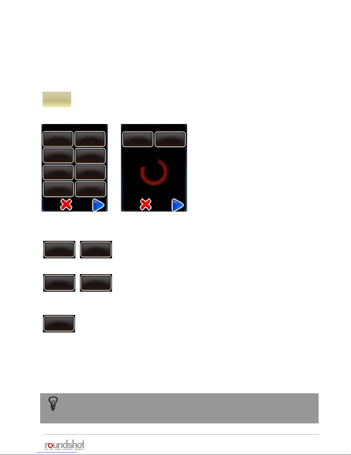
23/05/2019Roundshot VR Drive Instruction Manual – Firmware Version 2.023 76
4.4 USB settings
Click on “USB settings” to access the USB settings menu of the VR
Drive.
Click on “USB cable connected” to turn
on the USB functionalities:
• Release with USB cable
• Check white balance
• White balance
• Wait camera
• Memory check
• Release control
• Check manual mode
• Write identification
Some features might not be compatible
with all cameras!
USB settings
USB settings
USB cable
connected
on
release with
USB cable
on
check
white balance
off
memory check
without check
release control
on
White balance
use camera
settings
release with
USB cable
off
release with
USB cable
on
Set the “Release with USB cable” to “on” to allow the VR Drive to
release the camera through the USB cable only.
check
white balance
off
check
white balance
on
Set the “check white balance” to “on” to test the white balance on
the camera when starting a program. The VR Drive displays a
warning if the “automatic white balance” is active on the camera.
This avoids color mismatch between images.
The release with the USB cable is not guaranteed under all circumstances. The camera
software and communication with the VR Drive, CF card and other factors have an
influence on the speed of USB image release.
check manual
mode
off
write ID into
image
on
USB settings
wait camera
off
Choose from any white balance option in the list to set the white
balance on the camera.
White balance
use camera
settings
By default, the images are released automatically by the VR Drive using the camera release cable.
This is the most stable and reliable way to release the images. For the cameras compatible with
HDR mode it is possible to use the USB cable for image release and for other useful features.
Liveview
off
23/05/2019Roundshot VR Drive Instruction Manual – Firmware Version 2.023 77
4.4 USB settings (continued)
The “Write identification” tool will edit specific metadata tags on the camera. In
particular:
• Nikon : “User comment” tag
• Canon: “Owner” and “Artist” tags
Any data related to these tags, defined by the user on the camera will be lost. Please
make sure to redefine these information on the camera if necessary after using the VR
Drive with “write identification” function active.
check manual
mode
off
check
manual mode
on
Set the “check manual mode” to “on” to allow the VR Drive to
verify if the camera is working in manual mode. If it is not the case
it will either change it automatically to manual (whenever possible)
or display a warning message.
write
identification
off
write
identification
on
Set the “write identification” to “on” to allow the VR Drive to write
image position in the image metadata.
Combined with the VR Drive image bundler software, this
identification allows an easy image grouping and an automatic
image positioning. No need to export any program from the VR
Drive. All necessary information is embedded in the images.
The “Write identification” tool will embed specific image position information in the
image metadata. Not all HDR compatible cameras can be used. Please check the
camera compatibility list in our website to be sure your camera is compatible.
Check the section dedicated to the VR Drive image bundler software for more details
on the “write identification” tool
release control
off
release control
on
Set the “release control” to on when a high number of images are
to be captured in a short time. The VR Drive will make sure that
every image is released. If not a warning message will be displayed:
“cannot reach exposure time”
memory check
without check
memory check
stop if full
Activate the “memory check” to avoid losing images when the
memory card is full. Select one of these 3 options
• Without check: no memory check is done
• Stop if full: the program is stopped when the memory card is full
• Check at start: the VR Drive computes the necessary memory for
all images in a program. When starting a program it displays a
warning if there is not enough space remaining in the memory card
memory check
check at start
wait camera
off
wait camera
on
Set the “wait camera” to on when using long exposure times. The
VR Drive will wait for the “end of images capture” message from
the camera before releasing the next image.
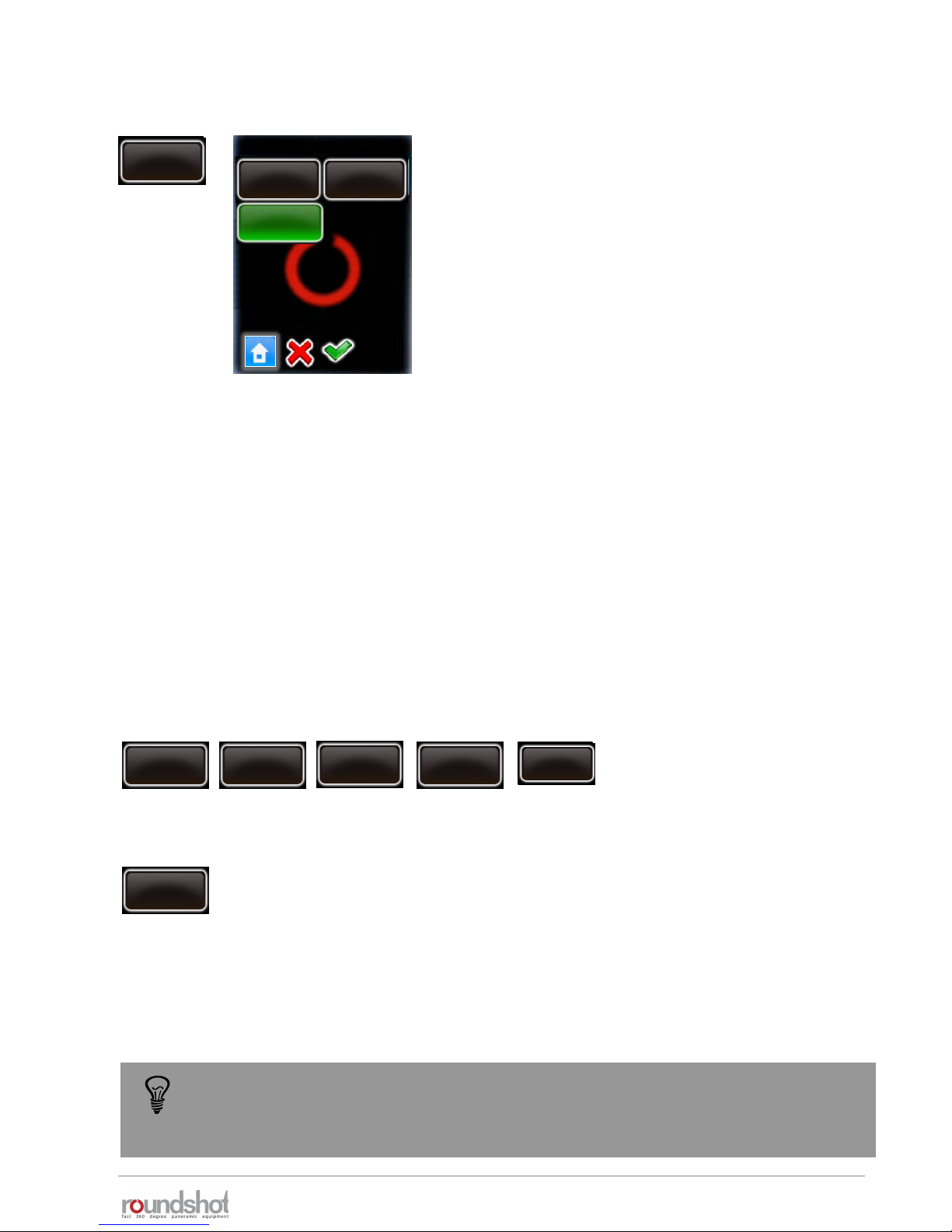
23/05/2019Roundshot VR Drive Instruction Manual – Firmware Version 2.023 78
4.4 USB settings (continued)
As the camera firmware needs to process all USB commands, this may result in delays and will
require longer pauses (after image).
We therefore recommend to use only those USB features that are essential, for example:
Recommended settings
USB cable
connected
on
release with
USB cable
on
release control
on
White balance
use camera
settings
write ID into
image
on
For USB release to work reliably, certain cameras require the release control to be set to “on”.
These cameras currently include the Canon EOS 80D + Canon EOS 1Dx mk ii.
Liveview
permanent
For selected USB-compatible cameras it is possible to
control the Liveview via USB.
These cameras currently include:
• all USB-compatible Canon EOS cameras
• Nikon D5200, D5300, D5500, D5600, D7000,
D7100, D7200, D7500, D4, D5, D810, D810a, D850
Liveview
off
permanent
on
Set Liveview to “on” or “permanent”.
Setting Liveview to “on” for a program has the benefit that a visual check of images on the
camera screen is possible.
Setting Liveview to “permanent” means that the mirror will be locked up from the start to the
very end of the program, allowing a significant reduction in vibration. This is particularly
practical and important for gigapixel projects with large cameras and bulky lenses with long
focals.
Liveview
permanent
As there is a great variety of USB features and the firmware of every camera model
reacts differently to USB commands, we recommend that you carefully test these
USB settings for your specific application.

23/05/2019Roundshot VR Drive Instruction Manual – Firmware Version 2.023 79
4.5 Auto exposure settings
Click on “auto exposure settings” to access the automatic exposure settings
menu of the VR Drive.
Click on “auto exposure” to activate the
automatic exposure functionality with
light meter sensor.
Then set the following parameters:
Auto exposure settings
auto exposure
off
Variation
strategy
ISO/ASA
auto exposure
settings
Aperture
Click on “var. strategy” and select the variation strategy
to be used:
• exposure: only the exposure time will change
according to light. ISO/ASA and aperture will be fixed
• exposure/aperture: both exposure and aperture will
change according to light. ISO/ASA will be fixed
• exposure/ISO/ASA: both exposure and ISO/ASA will
change according to light. Aperture will be fixed
• all: The VR Drive will automatically select all three
parameters according to light
Auto exposure settings
var. strategy
Auto exposure settings
exposure /
aperture
exposure /
ISO/ASA
all
exposure
ISO/ASA
aperture
Select a ISO/ASA value to use if the selected strategy is to keep ISO/ASA fixed.
Select an aperture to use if the selected strategy is to keep the aperture fixed.
auto exposure
on
Variation
strategy
ISO/ASA Aperture
When the VR Drive light meter sensor is connected to the VR Drive, and the camera is compatible
with VR Drive USB control, it is possible to use the VR Drive in a fully automatic way. This option is
only available for “Quality” and “HDR” modes
The VR Drive is able to measure the light before starting the image taking. Then, according to the
selected strategy and options, the VR Drive will set the correct exposure time, ISO/ASA and aperture
on the camera. The image taking process will then start automatically.
This way there is no need to adjust manually the exposure time on the camera or change the HDR
reference exposure time before every project. The image taking process is now fully automatic.

23/05/2019Roundshot VR Drive Instruction Manual – Firmware Version 2.023 80
4.6 Settings
Click on “settings” to access the VR Drive settings menu.
The “settings” menu is divided into 3 submenus:
• general
• database
• service menu
The “general” submenu consist of the following functions:
Click on “general” to access the “general” submenu.
Click on “language” to access the
“language” function.
Select the language of your choice.
Please note that the language will only be
active after closing the “edit program”
menu or after restarting the VR Drive.
Confirm with “OK”.
manual
movement
settings
general
database
service menu
default
movement
manual
movement
off in
Parkposition
yes
hardware id
software
has y motor
yes
aut. turn off
10 min
time
date
general
language
English
general
Deutsch
Italiano
Français
Español
English
language
4.6.1 Settings/general
general
settings
language
English
Chinese
Japanese
Português
Russian
language
exposure
meter
reduce screen
brightness
30s
diameter dolly
Wheels
200mm
rot. direction
linear axis
CW
diameter
linear axis
320mm
manual
movement
Simplified gui
off
general
remote radio
off

23/05/2019Roundshot VR Drive Instruction Manual – Firmware Version 2.023 81
4.6.1 Settings/general (continued)
Click on “date” to access the “date” function.
Set the year, month and day
Confirm every entry with “next” or cancel with “X”.
Click on “time” to set the hours and minutes of your VR Drive.
Enter the hours and minutes.
Confirm with “OK” or cancel with “X”.
Click on “auto turn off” to define the time for automatic shut down
of the VR Drive.
This function is designed to help save battery.
For extended operation times the auto turn off time can be
increased.
Enter the time in minutes.
Confirm with “OK” or cancel with “X”.
1
20
year
2012
[1970..2100]
month
1
[1..12]
day
20
[1..31]
18
30
hours
18
[0..23]
minutes
30
aut. turn off
[0..120]
10 min
date
auto turn off
time

23/05/2019Roundshot VR Drive Instruction Manual – Firmware Version 2.023 82
4.6.1 Settings/general (continued)
Click on “has y motor” to activate / deactivate the y-motor.
For VR Drive “full” select “yes”.
For VR Drive “semi” select “no”.
Click on “software” to display information on the software
This function consists of
• key
• version
• IP
software
key
version
ip
software
has y motor
yes
has y motor
no
Click on „reduce screen brightness“ to change time of non activity
before the VR Drive reduces the screen brightness.
Enter the delay (in s).
If setting this value to 0s the VR Drive will never reduce the screen
brightness. This might be useful outdoors, but will use more
battery.
The standard value is: 30s
Confirm with “OK” or cancel with “X”.
Beschleunigung
50
acceleration
reduce screen
brightess
30s
Beschleunigung
reduce screen brightness
[0..60]
30 s

23/05/2019Roundshot VR Drive Instruction Manual – Firmware Version 2.023 83
4.6.1 Settings/general (continued)
Click on “key” to display the software key.
The software key is used to activate the VR Drive modes (“quality”,
“speed”, “turntable”, “video”, “timelapse”, “HDR”).
This key is specific to the VR Drive hardware ID.
It will be delivered with your VR Drive or when upgrading to a new
software mode.
If you received a new key after upgrading, enter it here.
Confirm with “OK”.
After entering a valid key, the software displays the available
software modes.
When entering an invalid key, the last valid key will be loaded.
Confirm with “OK”.
key
key
A983BB9CD73A98CD
key
The software key is
valid. The following
modes are now
available:
quality
speed
turntable
video
version
version
IP
Firmware : V2.023
(21.12.2018)
Bootloader : V1.02
ip
192.168.1.15

23/05/2019Roundshot VR Drive Instruction Manual – Firmware Version 2.023 84
4.6.1 Settings/general (continued)
Click on “hardware ID” to display the unique hardware
identification number of your VR Drive.
This ID is at the same time the serial number and is stored in the
“Club VR Drive” database.
Together with the software key this hardware ID activates the VR
Drive software mode.
The hardware ID cannot be modified.
Confirm with “OK”.
Click on “off in park position” to set the preferences for the VR
Drive parking position.
Enter the desired parking position horizontally (“X”) and vertically
(“Y”).
For example, to tilt the camera 90° down (for transport), enter:
• X: 0° (or any value)
• Y: 90°
Confirm with “OK” or cancel with “X”.
hardware id
BC7893A8FF03FA7
hardware id
off in
parkposition
X
0
Y
90
[-999.9..999.9]
[-90.0..90.0]

23/05/2019Roundshot VR Drive Instruction Manual – Firmware Version 2.023 85
Click on „manual movement“ to set the preferences for manual
positioning of the VR Drive.
Click on „speed“.
Enter the speed of X / Y movement (in seconds).
The standard settings are:
• X: 10s
• Y: 20s
Confirm with “OK” or cancel with “X”.
Click on „acceleration“.
Enter the degree of speed adjustment:
• 1%: slow adjustment
• 100%: fast adjustment
The acceleration value is computed when setting up the program in
the Program Wizard and depends on the focal length:
• <20mm: 100%
• 20mm to 50mm: 50%
• >50mm: 20%
Confirm with “OK” or cancel with “X”.
speed
16/20s
acceleration
15%
manual movement
Beschleunigung
X Y
s
s
10 20
[6..9999] [8..9999]
The manual movement speed and acceleration parameters are used when the VR
Drive is moved with the remote radio release or with the touch screen unit for point
definition (video mode).
4.6.1 Settings/general (continued)
manual
movement
speed
16/20s
speed
10/20s
acceleration
10%
acceleration
[1..100]
10 %
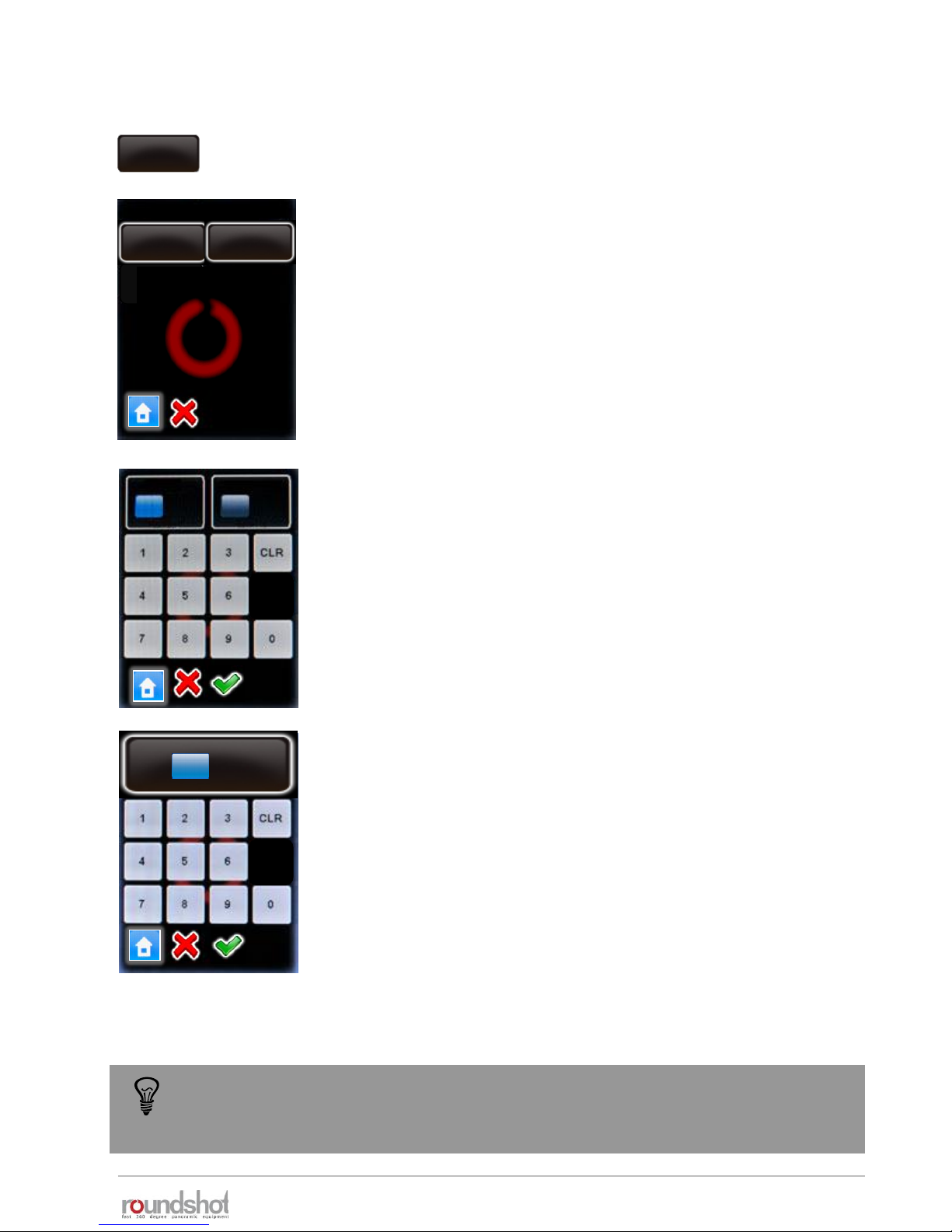
23/05/2019Roundshot VR Drive Instruction Manual – Firmware Version 2.023 86
Click on „default movement“ to set the preferences for automatic
positioning of the VR Drive.
Click on „speed“.
Enter the speed of X / Y movement (in seconds).
The standard settings are:
• X: 6s
• Y: 10s
Confirm with “OK” or cancel with “X”.
Click on „acceleration“.
Enter the degree of speed adjustment:
• 1%: slow adjustment
• 100%: fast adjustment
The acceleration value is computed when setting up the program in
the Program Wizard and depends on the focal length:
• <20mm: 100%
• 20mm to 50mm: 50%
• >50mm: 20%
Confirm with “OK” or cancel with “X”.
speed
8/10s
acceleration
50%
default movement
Beschleunigung
X Y
ss6 10
[6..9999] [8..9999]
50
acceleration
The standard movement speed and acceleration is applied when the VR Drive moves
from zero position to start a program, back into zero position after a program or
from/into a parking position.
4.6.1 Settings/general (continued)
default
movement
speed
6/10s
acceleration
50%
Beschleunigung
acceleration
[1..100]
50 %
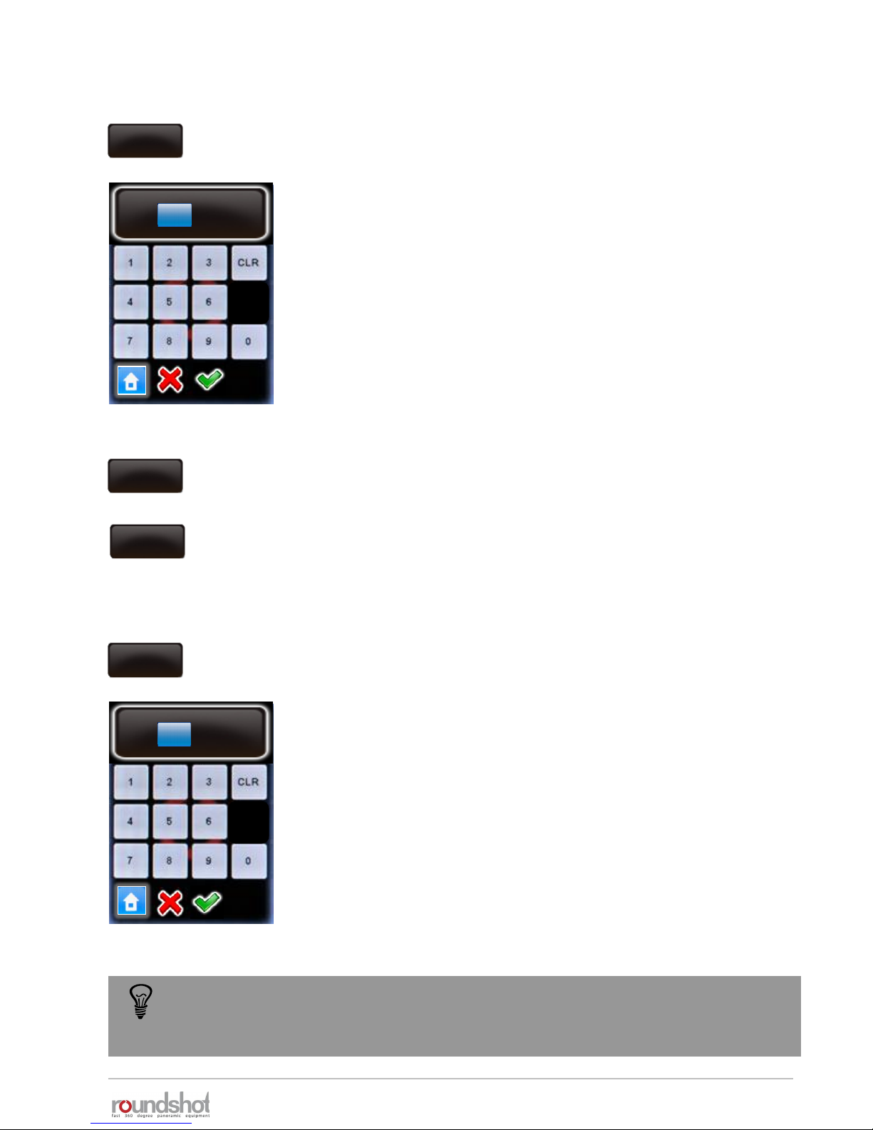
23/05/2019Roundshot VR Drive Instruction Manual – Firmware Version 2.023 87
Click on „diameter linear axis“ to change the size of the wheel
used on your linear axis.
Enter the diameter (in mm). Please make sure that the entered
value corresponds to the real size of the wheel.
The default size is 151mm.
Confirm with “OK” or cancel with “X”.
Beschleunigung
50
acceleration
The linear rail and dolly parameters might change according to the delivered
material. Please make sure to enter the correct values and check with Seitz team if
not sure.
4.6.1 Settings/general (continued)
diameter
linear axis
151mm
Beschleunigung
diameter linear axis
[10..1000]
151 mm
Click on “rot. Direction linear axis” to define the positive rotation
direction of the main wheel of the linear axis
2 choices are available:
• CW
• CCW
rot. direction
linear axis
CW
rot. direction
linear axis
CCW
Click on „ diameter dolly wheels “ to change the size of the wheels
used on your dolly.
Enter the diameter (in mm). Please make sure that the entered
value corresponds to the real size of your dolly.
The default size is 200mm.
Confirm with “OK” or cancel with “X”.
Beschleunigung
50
acceleration
diameter
dolly wheels
200mm
Beschleunigung
diameter dolly wheels
[10..1000]
200 mm

23/05/2019Roundshot VR Drive Instruction Manual – Firmware Version 2.023 88
4.6.1 Settings/general (continued)
Click on „exposure meter“ to set the sensitivity, the measuring
points and the range of exposure values allowed.
exposure
meter
Click on “wake on radio” to activate / deactivate the wake-up
function of the radio release unit for the VR Drive remote control.
Deactivate the wake on radio with “no”.
Activate the wake on radio with “yes”.
With the radio receiver deactivated it is possible to turn the VR
Drive left/right/up/down and to start a program. It is also possible
to turn the VR Drive on even if it is switched off.
This is the reason why the battery discharges faster with the radio
receiver activated. The VR Drive displays a warning message.
Confirm with “OK” or cancel with “X”.
remote radio
off
remote radio
on
warning
The battery will
discharge faster when
using this option.
Continue anyway?
speed
16/20s
acceleration
15%
exposure meter
speed
16/20s
exposure
constant
25
exposure
sample
1
speed
16/20s
auto
exposure
ranges
speed
16/20s
exposure
constant
25
Click on „exposure constant“ to adapt the sensitivity of the light
meter on a scale from 1 (least sensitive) to 255 (most sensitive).
The standard value is 25.
Increase this value if the images are consistently too dark.
Decrease this value if the images are consistently too bright.
Confirm with “OK” or cancel with “X”.
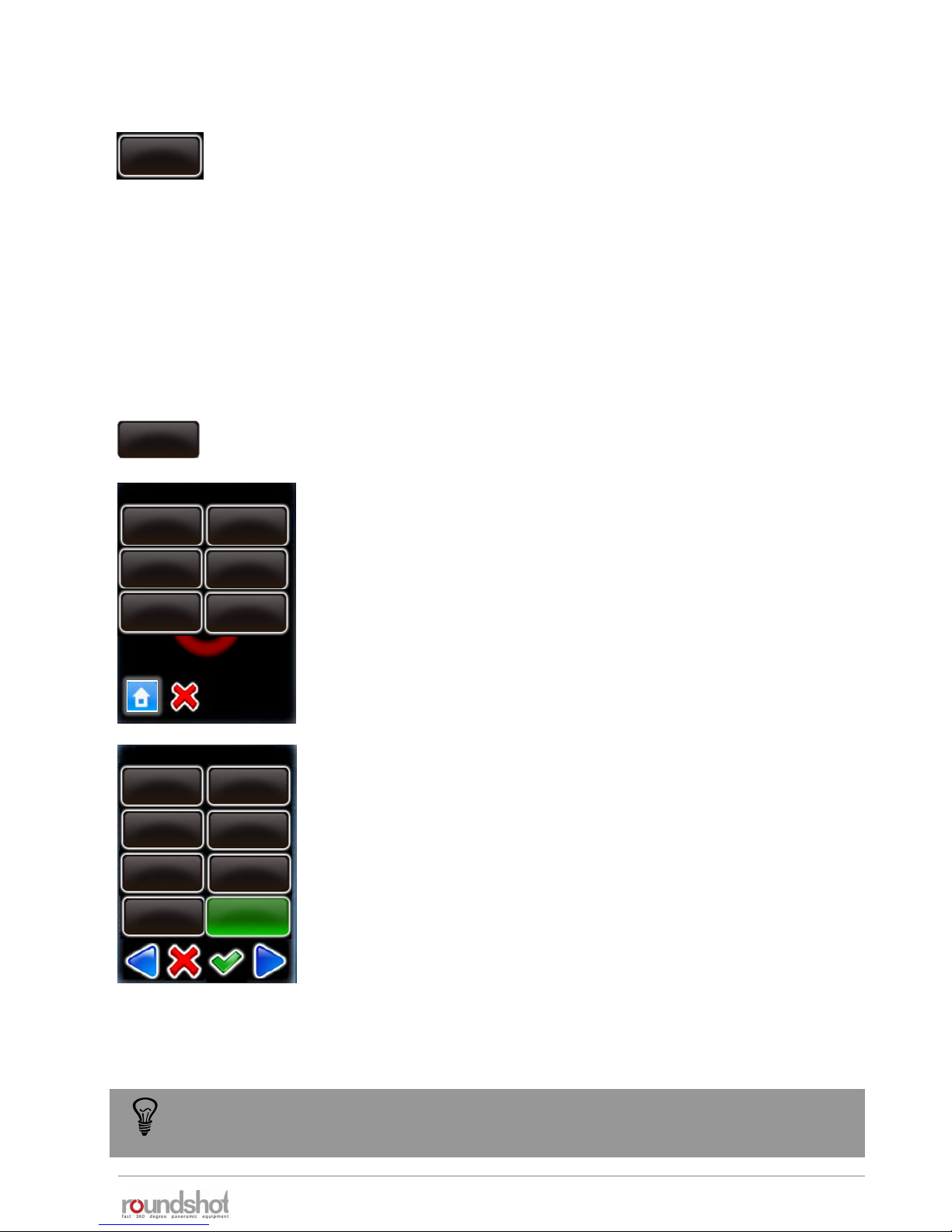
23/05/2019Roundshot VR Drive Instruction Manual – Firmware Version 2.023 89
4.6.1 Settings/general (continued)
Click on „auto exposure ranges“ to define the range of values
allowed when the automatic light meter tool is active.
It is possible to define the maximum and the minimum value for
the following parameters:
• ISO
• Aperture, where min = open f-stop, max = closed f-stop
• Exposure, where min = fastest speed, max = slowest speed
This prevents the VR Drive from selecting extreme values to adjust
the camera to the current light.
For example, click on „max. exposure“.
Enter the maximum exposure time allowed. (In this example 1s)
In this example the VR Drive will never select an exposure time
longer than 1s to avoid too slow image capture.
Confirm with “OK” or cancel with “X”.
speed
16/20s
acceleration
15%
auto. exposure ranges
auto exposure
ranges
speed
16/20s
min. ISO
max. ISO
speed
16/20s
acceleration
15%
speed
16/20s
min. aperture
max. aperture
speed
16/20s
acceleration
15%
speed
16/20s
min. exposure
max. exposure
max . exposure
5s
4s
2.5s
1.6s
2s
3.2s
1.3s
1s
The auto exposure ranges are applied for all automatically computed values. If a
parameter is set manually in the VR Drive these limits are not applied.
acceleration
15%
speed
16/20s
exposure
sample
1
Set the number of light measurements by changing the “exposure
sample” value.
When setting this value to “1”, only one spot measurement will be
taken. Setting it to “6”, for example, will measure – for a 360°
panorama – at every 60°.
When starting a program, the VR Drive will create a measurement
rotation. For panoramas < 360°, it will center the measurements
within the relevant angle of the panorama.

23/05/2019Roundshot VR Drive Instruction Manual – Firmware Version 2.023 90
4.6.1 Settings/general (continued)
Click on “simplified gui” to activate / deactivate the simplified gui
screen on the VR Drive
If active, the simplified screen will allow the user only to select a
program and to start it. No editing or new program creation is
possible
simplified gui
on
simplified gui
off
(Press to view settings)
When the simplified gui is active it is not possible to access the edit menu to
deactivate it. It is necessary to follow the procedure below:
Restart the VR Drive and
click on the “Press to
view settings section”
during start up.
settings
general
service menu
database
Press “general” and
browse the parameter
“simplified gui”
Press “simplified gui” to
turn it “off”
VR Drive
press
manual
movement
Simplified gui
off
general

23/05/2019Roundshot VR Drive Instruction Manual – Firmware Version 2.023 91
4.6.2 Settings/database
Click on “database” to access the database functions of your VR
Drive.
The “database” submenu consist of the following functions:
• my cameras
• presets
• delete all programs
• reset to factory
• Import
• export
Click on “my cameras” to display the list of favorite cameras used
with your VR Drive.
Add a new camera by
clicking the button.
For example for
Nikon D700:
my cameras
database
my cameras / page 1
my cameras presets
delete all
programs
reset to
factory
export
import
Nikon
D3
Canon
5D
PhaseOne
P65+
Nikon
Kodak
Canon Fuji Finepix
SONY DSC
Olympus
Panasonic
Leica
Nikon
Nikon
D700
D1 D1H
D1X
D50
D70s D80
D90
D200
Nikon
D300
Canon
5D mk 2
Nikon
D700
PhaseOne
P65+
my cameras / page 1
database
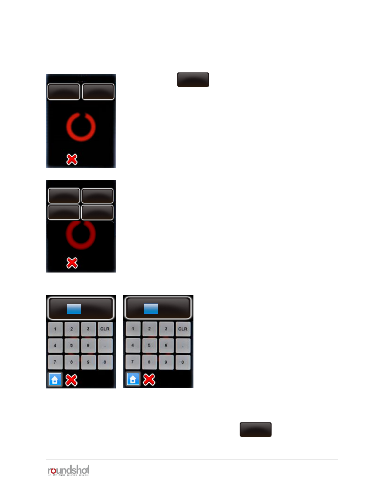
23/05/2019Roundshot VR Drive Instruction Manual – Firmware Version 2.023 92
4.6.2 Settings/database (continued)
To edit the parameters of a camera, select the camera.
P2
It is possible to edit the sensor size in mm.
Select “X (mm)” and “Y (mm)”.
Enter the new values in mm.
Confirm with “OK”.
To delete a camera from the list, select the camera and click
The camera will still be in the database, but removed from the “favourites” list.
Click
The camera parameters are displayed as follows:
edit
P2
delete
edit
X (mm)
[0.0..400.0]
36 mm
Y (mm)
[0.0..400.0]
23.9 mm
delete
Nikon
D3
X (mm)
36mm
Y (mm)
23.9mm
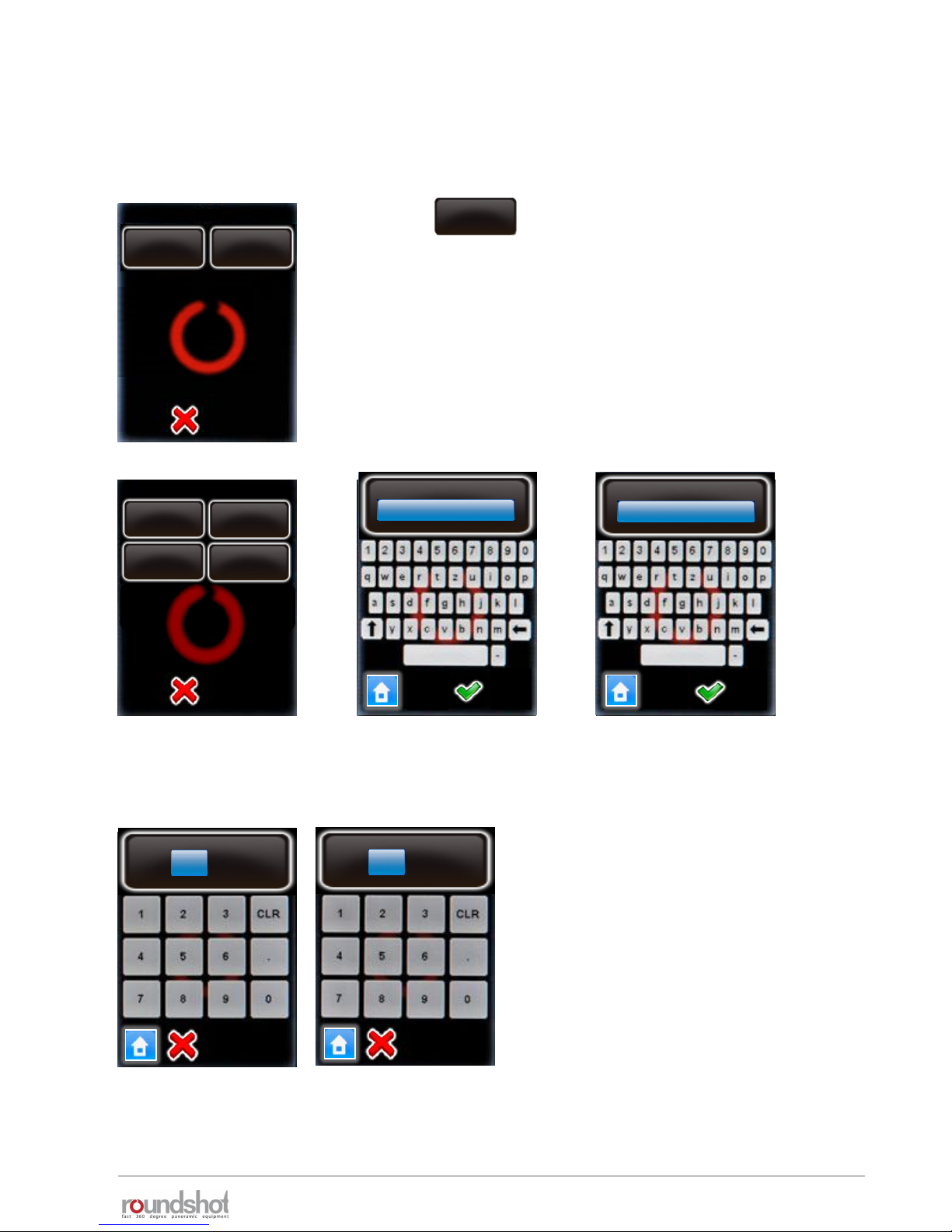
23/05/2019Roundshot VR Drive Instruction Manual – Firmware Version 2.023 93
4.6.2 Settings/database (continued)
To add a new camera that is not in the database, select any camera in the list and overwrite its
values.
P2
Enter the camera brand, camera type and X/Y (mm).
Confirm with “OK”.
Click
The camera parameters are displayed as follows:
edit
P2
delete
edit
X (mm)
[0.0..400.0]
36 mm
Y (mm)
[0.0..400.0]
23.9 mm
camera
Nikon
type
D3
Nikon
Nikon
D3
X (mm)
36mm
Y (mm)
23.9mm
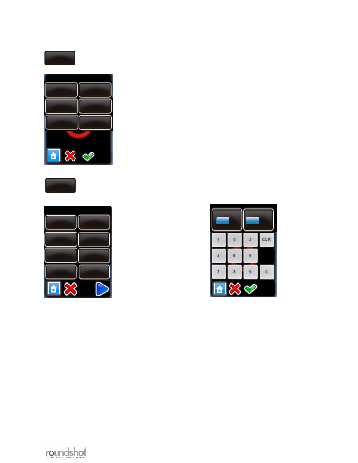
23/05/2019Roundshot VR Drive Instruction Manual – Firmware Version 2.023 94
4.6.2 Settings/database (continued)
Click on “presets” to define the parameter preferences of your VR
Drive.
The “presets” are grouped by software mode:
• “quality”
• “speed”
• “turntable”
• “video”
• “HDR”
• “timelapse”
Click on “quality”, “speed”, “turntable”, “video”, “timelapse” or
“HDR” to set up the presets.
Click on the preset to
modify, for example:
When always using the same camera, it may be more efficient to set the A-value to a
preset. This way, this value will always be automatically loaded every time a new program is
created.
The table on the following pages summarises all program parameters created in the
“Wizard” or loaded as “presets” for the different VR Drive modes.
presets
presets
turntable
video
HDR
speedquality
presets
quality
info
Nikon
D3
focal lenght
24 mm
A/B value
0/ 0mm
angle mode
cylindrical
Edit P1 / page 1
A
mm
[1..999]
B
mm
[1..999]
0
0
info
Nikon D3
focal length
24mm
A/B value
1/1 mm
angle mode
cylindrical
Mode
quality
X
360°
Y
88°
timelapse

4.6.2 Settings/database (continued)
units function
q
speed
turntable
timelapse
video
HDR
info
text
Information on project
✓
✓✓ ✓
✓
✓
camera
text
Camera brand + type; used for automatic calculation
of rows in “quality”, “speed” + “HDR” mode
✓ ✓✓ ✓ ✓ ✓
focal
length
mm
For automatic calculation of rows in “quality” and
“speed” mode
✓ ✓✓ ✓ ✓ ✓
A/B
value
mm Information to determine center and nodal points
✓ --✓ -- -- ✓
angle
mode
various
Automatic calculation of rows (cylindrical, spherical) ,
manual or visual programming
✓ --✓ -- -- ✓
X-FoV
degrees Horizontal angle (field of view)
✓ --✓ ✓ -- ✓
Y-FoV
degrees Vertical angle (field of view)
✓ --✓ -- -- ✓
sequence
various
Sets the direction of image release (zig-zag, vertical,
snake, center-up, center-down, top-down, bottomup)
✓ --✓ -- -- ✓
speed X/Y
seconds
Speed in x and y dimension from position to position
✓ --✓ ✓ -- ✓
Nb images
fix/var
Use fixed or variable number of images for every row
✓ --✓ -- -- ✓
rows
elevation: °
images: #
Position of image release in X/Y dimension
✓ --✓ ✓ -- ✓
pause
position
seconds
Pause before or after reaching positions
✓ ---- ✓ ✓ ✓
overlap
X %, Y %
Overlap between images in x and y dimension
✓ --✓ -- -- ✓
orientation
portrait
landscape
Camera orientation
✓ --✓ -- -- ✓
pause
image
seconds
Pause before or after releasing the images
✓ ---- ✓ ✓ ✓
release
time
seconds
Duration of release signal (electronic cable, not USB)
✓ ---- ✓ ✓ ✓
repeat
X, degree
Number of times a program is repeated with offset
angle
✓ ✓✓ ✓ ✓ ✓
Panorama programs
23/05/2019Roundshot VR Drive Instruction Manual – Firmware Version 2.023 95

23/05/2019Roundshot VR Drive Instruction Manual – Firmware Version 2.023 96
4.6.2 Settings/database (continued)
units function
quality
speed
turntable
timalapse
video
HDR
orientation
CCW, CW
Direction of rotation – counter-clockwise, clockwise
✓ ✓✓ ✓ ✓ ✓
manual
release
off/on Manual release of camera in every position
-- ---- -- -- ✓
mirror
release
seconds
Time for release of camera mirror prior to image-
taking
-- ---- -- -- ✓
bracketing
1x..9x,
special
Number of multiple releases per position; special for
continuous signal
✓ ---- ✓ -- --
lens type
fisheye
non-fisheye
Fisheye or traditional lens (non-fisheye) – to compute
rows
✓ --✓ -- -- ✓
floor patch
on/off, °
Optional floor image for spherical panoramas
✓ --✓ -- -- ✓
back to start
on/off
Optional return movement for horizontal sequences
to avoid cable damage
✓ --✓ -- -- ✓
USB settings
various
USB features for image release, white balance,
memory check, release control, check manual mode,
wait for camera, Liveview
✓ --✓ ✓ ✓ ✓
auto exp.
settings
variation
strategy
Select automatic or fixed exposure time, automatic
aperture or automatic ISO/ASA
✓ --✓ ✓ ✓ ✓
timer
seconds
Delay time before a program sequence is launched
✓ ---- ✓ ✓ ✓
acceleration
%
Degree of speed adaptation (1% slow, 100% fast)
✓--✓ ✓
-- ✓
Panorama programs (continued)

23/05/2019Roundshot VR Drive Instruction Manual – Firmware Version 2.023 97
4.6.2 Settings/database (continued)
units function
quality
speed
turntable
timalapse
video
HDR
aperture
f
f-stop on the lens used for the HDR exposure
-- ---- -- -- ✓
ISO/ASA
ISO/ASA
ISO/ASA used for the HDR exposure
-- ---- -- -- ✓
Nb bracketed
images
#
Number of images released per position/bracketing
for HDR
-- ---- -- -- ✓
aperture
steps
f
Difference in f-stops from one bracketed image to
the next for HDR
-- ---- -- -- ✓
exp
sequence
various Fast to slow or slow to fast exposure times
-- ---- -- -- ✓
start point
X/Y
degrees
Starting position for video in X/Y dimension
--✓-- --
✓
--
points
degrees,
seconds
For definition of every point in video sweep: X/Y
position, speed between points, acceleration (degree
of speed adaptation), pause at every point
--✓-- --
✓
--
image every
... sec/deg
seconds/
degrees
release of images between points in timelapse mode
-- ---- --
✓
--
release
mode
second/
position
Defines the way the images will be released in
timelapse mode
-- ---- -- ✓ --
aperture
compensation
off/on
Option to compensate exposure speeds at limit with
f-stop for HDR
------ --
-- ✓
HDR steps
table
Table of exposures, f-stops and ISO/ASA for every
bracketed image
-- ---- -- --
✓
start/end Y
degrees
Vertical FOV to distribute rows in angle mode
“manual”
✓ --✓ ✓ -- ✓
start angle
X/Y
degrees Starting point coordinates in visual angle mode
✓ --✓ -- -- ✓
end angle
X/Y
degrees
End point coordinates in visual angle mode
✓ --✓ -- -- ✓
ref exposure
speed
seconds
Average exposure speed on which the HDR table is
built
-- ---- -- -- ✓
Panorama programs (continued)
HDR programs
Timelapse/video programs

23/05/2019Roundshot VR Drive Instruction Manual – Firmware Version 2.023 98
4.6.2 Settings/database (continued)
Click on “delete all programs” to remove all programs from your
VR Drive.
Confirm with “next” or cancel with “X”.
After deleting all programs a default program in “quality” mode will
be stored as “P1”.
All settings (general (time settings etc.) and database (camera,
presets) will remain unchanged.
Click on “reset to factory” to remove all programs and reload the
default factory settings.
Confirm with “next” or cancel with “X”.
After deleting all programs a default program in “quality” mode will
be stored as “P1”.
The settings (general (time settings etc.) and database (camera,
presets) will be created from factory settings.
delete all
programs
delete programs
Do you really want to
delete all programs?
Do you really want
to reset to factory
settings?
reset to
factory
reset to factory

23/05/2019Roundshot VR Drive Instruction Manual – Firmware Version 2.023 99
4.6.2 Settings/database (continued)
import
Import
If a program number already
exists, would you prefer to
overwrite the old one or
append as new?
export
xml type
Data save successful
Export
Seitz
Papywizard
append
overwrite
Click on “import” to load previously backed-up VR Drive programs.
If a program number already exists in the VR Drive there are two
options:
• Overwrite the existing program number with the imported one
• Append the existing program to the VR Drive programs
Confirm or cancel with “X”.
The programs are loaded to the VR Drive.
Click on “export” to export program settings.
The “Papywizard” option exports the exact location (pitch/roll) of
every image released in the program sequence to an xml file in the
papywizard standard. This xml file can then be used in the stitching
software for accurate allocation of images .
The “Seitz” option exports all programs to back-up files that can be
shared between VR Drives or can be re-imported later, for example
after a reset to factory settings.
Which format should be taken
to write the xml files?
For importing and exporting data please connect the original
Roundshot USB stick into the USB slot of the VR Drive.
Important: The USB stick needs to be inserted prior to loading the
import or export commands.
Back up your programs in the Seitz format from time to time. This ensures that no
program data is lost in the case that the VR Drive has to be reset to factory settings.
Papywizard format Seitz format
(for stitching software) (for back-up / can be reimported
into VR Drive)
 Loading...