

Page 1
92RC60800
Jeep YJ 1-1/4” Body Lift
Thank you for choosing Rough Country for all your suspension needs.
This body lift fits manual shift models only!!!
Rough Country recommends a certified technician install this system. In addition to these instructions, professional
knowledge of disassembly and reassembly procedures as well as post install ation checks must be known. Attempts to
install this system without this knowledge and expertise may jeopardize the integrity and/or operating safety of the vehicle.
Please read the instructions before beginning the installation. Check the kit hardware against the Kit Contents shown.
Be sure you have all needed parts and know where they go. If there are any questions about the installation or installation steps call our tech line at 800-222-7023.
PRODUCT USE INFORMATION
As a general rule, the taller a vehicle is, the easier it will roll. Offset, as much as possible, what is lost in rollover resistance by increasing tire track width. In other words, go "wide" as you go "tall". Many sportsmen remove their mud tires
after hunting season and install ones more appropriate for street driving; always use as wide a tire and wh eel combination as possible to enhance vehicle stability.
Seat belts and shoulder harnesses should be worn at all times. Avoid situations where a side rollover may occur. Generally, braking performance and capability are decreased when significantly larger/heavier tires and wheels are used. Take
this into consideration while driving.
Do not add, alter, or fabricate any factory or after-market parts to increase vehicle
height over the intended height of the Rough Country product purchased. Mixing component brands is not recom mended. Rough Country makes no claims regarding lifting devices and excludes any and all i mplied claims. We will not
be responsible for any product that is altered.
If you have any questions concerning the design, function, and/or correct use of our products please contact one of our
customer service representatives us at 800-222-7023.
NOTICE TO DEALER AND VEHICLE OWNER
Any vehicle equipped with any Rough Country product should have a “Warning to Driver” decal installed on the
inside of the windshield or on the vehicle’s dash. The decal should act as a constant reminder for whoever is oper-
ating the vehicle of its unique handling characteristics.
INSTALLING DEALER - it is your responsibility to install the warning decal and forward these installation instructions on
to the vehicle owner for review. These instructions should be kept in the vehicle for its service life.
IMPORTANT PRE—INSTALLATION INSTRUCTIONS
Prior to beginning this installation it is always good to use a penetrating oil and spray all body mount hardware
that will be removed. Typically the stock body bushings will need to be checked to ensure they are in good condition. If the stock body bushings are cracked or deteriorated they must be replaced. This should be performed
as the body lift is installed. Failure to perform this maintenance could jeopardize the operating safety of the vehicle.
Tools Needed:
Floor Jack
Jack Stands
3/8” Socket / Wrench
1/2” Socket / Wrench
5/8” Socket / Wrench
13mm Socket / Wrench
19mm Socket / Wrench
Drill Motor
1/4” Drill Bit
Page 2
KIT CONTENTS
B
A
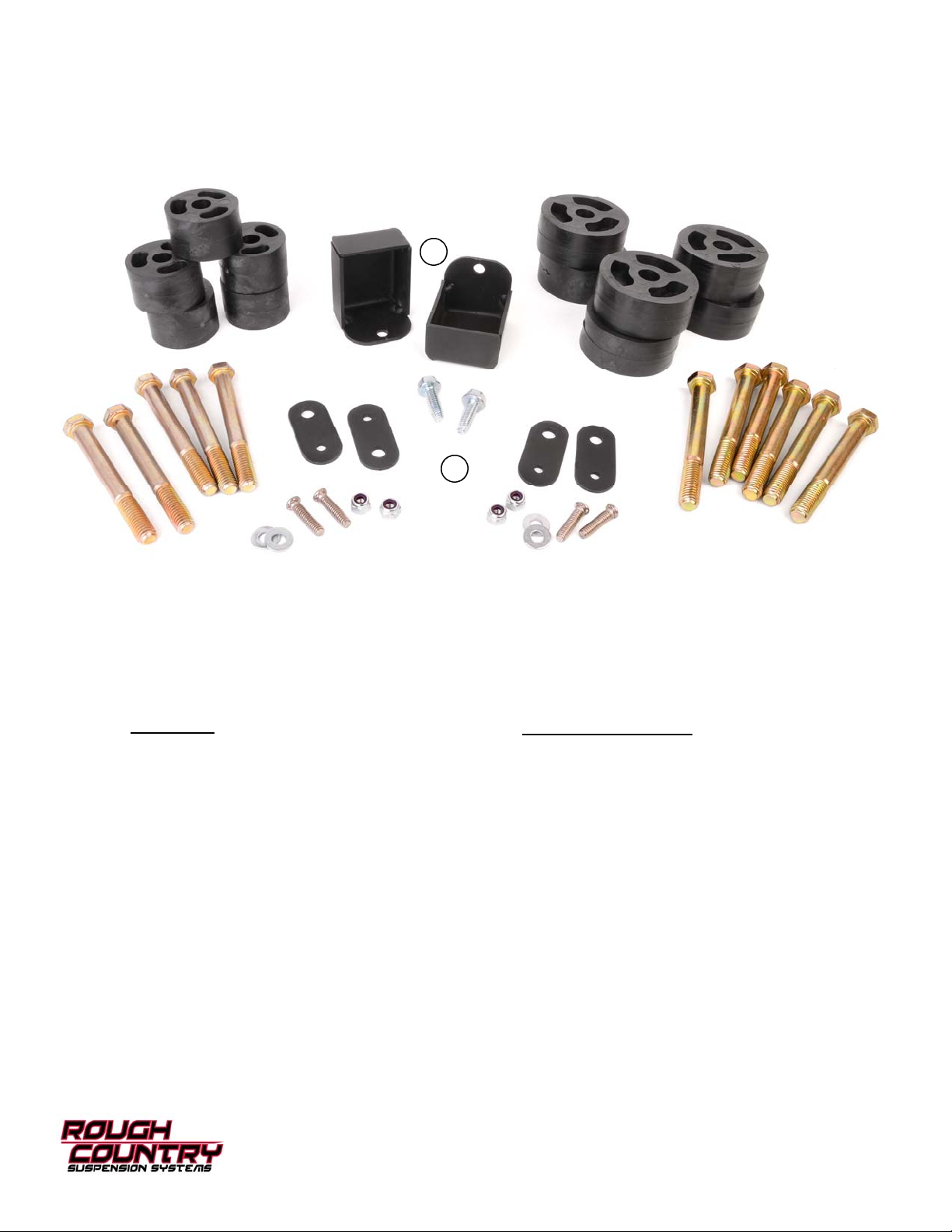
Kit Includes:
6-1 1/4” x 3” Diameter Body Pucks
5-1 1/4” x 2” Diameter Body Puck
4-Radiator Shroud Drop Brackets (A)
2-Radiator Core Support Brackets (B)
Kit Hardware Breakdown:
RC608Bag1:
6-1/2” x 4 1/2” Bolt
5-7/16” x 4” Bolt
4-1/4” x 1” Self Clinch Stud
4-1/4” Lock Nut
4-1/4” Flat Washer
2-5/16” Self Tapping Bolt
Page 3
INSTALLATION INSTRUCTIONS
1. Disconnect the negative battery cable using 1/2” wrench.
2. Remove the plastic jeep cover from front of vehicle using a 3/8” wrench and the metal plate that secure the brake
line.
3. Disconnect air intake from air filter housing and from throttle body. Depending on year remove coolant re servoir and
power steering reservoir from fan shroud.
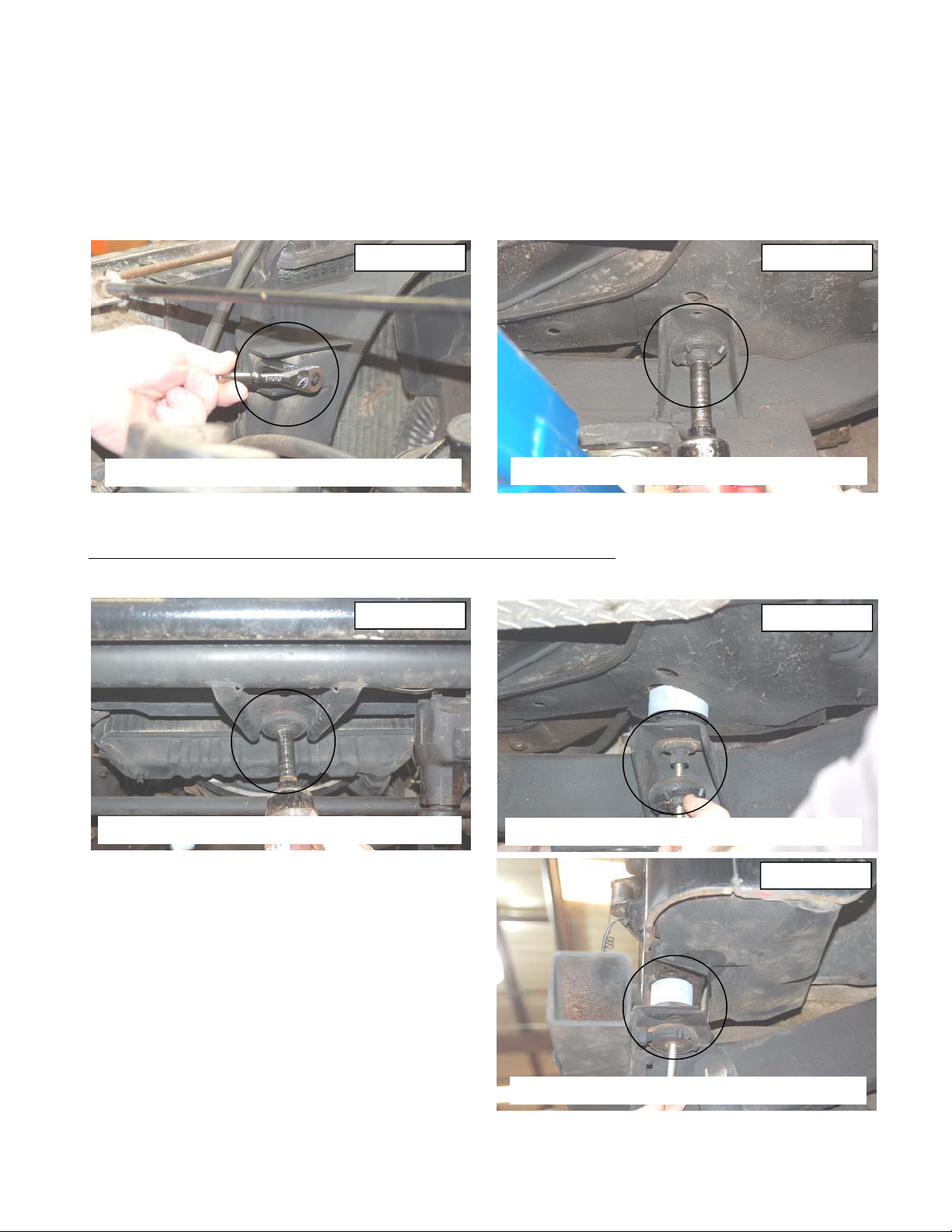
4. Remove the 4 bolts from radiator shroud using a 13mm socket. See Photo 1.
5. Loosen all eleven body mount bolts using 5/8” socket. There is one in center of grill, three under each door, two
above rear axle and two at each rear corner. See Photo 2.
Photo 1 Photo 2
REMOVE THE SHROUD HARWARE
LOOSEN ALL BODY MOUNTS
6. Only remove bolts on one side at a time. Front center bolt must be remove for both sides. See Photo 3.
7. Using floor jack or jack stand and a wood block raise body from frame only enough to safely install the body puck.
Take Caution not to over extend wires, brake lines, cables and steering shaft
.
8. The 1 1/4” tall x 3” diameter body pucks install on the three body mounts under doors. See Photo 4. Secure using
the supplied 1/2” x 4 1/2” bolts.
Photo 3
REMOVE FRONT CENTER SUPPORT BOLT
9. The smaller 1 1/4” tall x 2” diameter pucks will install the
INSTALL THE 3” DIAMETER BODY PUCKS
Photo 4
Photo 5
remaining five body mounts. Use the supplied 7/16” x 4”
bolts. See Photo 5.
INSTALL THE 2” DIAMETER BODY PUCKS
Page 4
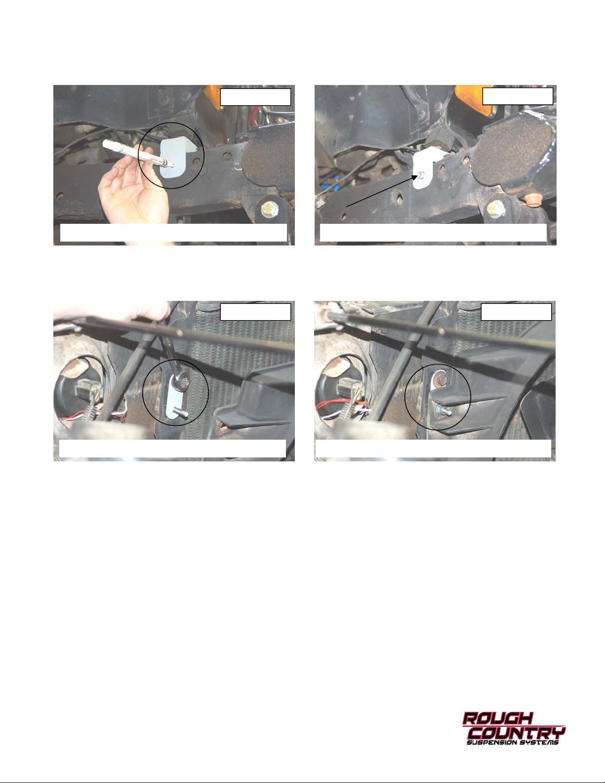
10. Install the new front bump stop extension under the bump stop on radiator core support. Using the bracket as a template mark hole to be drilled. See Photo 6.
11. Drill a 1/4” hole in frame and secure using the supplied 5/16” x 1” self tapping bolt and a 13mm socket to tighten.
See Photo 7. Do not over tighten the bolt. Repeat for the opposite side.
Photo 6
MARK THE HOLE TO BE DRILLED INSTALL THE SUPPLIED 5/16” X 1” BOLT
12. After all body puck are in tighten all bolts. 19mm socket for the 1/2” bolts and 16mm for the 7/16” bolts.
13. Install the 1/4” clinch studs into radiator drop bracket using hammer and small socket.
14. Install the four radiator fan shroud drop brackets using stock hardware. See Photo 8.
15. Reinstall the shroud on the bracket with the supplied 1/4” lock nuts and flat washers. See Photo 9.
Photo 8 Photo 9
Photo 7
INSTALL THE SHROUD BRACKETS REINSTALL THE SHROUD TO THE BRACKETS
16. Reinstall the coolant reservoir and power steering reservoir to the fan shroud if appli cable. Use a 13mm for stock
bolts and 7/16” for new nuts.
17. Reconnect the air intake to the air filter housing and throttle body.
18. Reinstall plastic jeep cover and metal plate using 3/8” socket. Metal plate should go under the body mount. Install
hard brake line back into clips.
19. Re-Check all fastener to confirm all components are not binding or in the way of moving parts.
POST INSTALLATION INSTRUCTIONS
1. Check all fasteners for proper torque. Check to ensure there is adequate clearance between all rotating, mobile,
fixed and heated members. Check steering gear for interference and proper working order. Test brakes.
2. Check to ensure metal brake lines have sufficient slack to eliminate interference and maintain proper working orde r.
Failure to perform inspections may result in component failure.
3. Readjust headlights to proper settings.
MAINTENANCE INFORMATION
It is the buyers ultimate responsibility to have all bolts/nuts checked for tightness after the first 100 miles and then
every 1000 miles. A qualified professional mechanic must inspect wheel alignment steering system, suspension and
driveline systems at least every 3000 miles.
Thank you for choosing Rough Country for all your suspension needs.
 Loading...