

Page 1
9286200
Nissan 04 –up Titan 3” Suspension Kit
Thank you for choosing Rough Country for all your suspension needs.
Rough Country recommends a certified technician install this system. In addition to these instructions, professional
knowledge of disassemble/reassembly procedures as well as post installation checks must be known. Attempts to install
this system without this knowledge and expertise may jeopardize the integrity and/or operating safety of the vehicle.
Please read instructions before beginning installation. Check the kit hardware against the parts list. Be sure you have
all needed parts and know where they go. Also please review the tool list and make sure you have the necessary tools
to install the kit.
As a general rule, the taller a vehicle is, the easier it will roll. We strongly recommend, because of rollover possibility, that
seat belts and shoulder harnesses should be worn at all times. Avoid situations where a side rollover may occur. Generally, braking performance and capability are decreased when larger/heavier tires and wheels are used. Take this into
consideration while driving. Do not add, alter, or fabricate any factory or after-market parts to increase vehicle height
over the intended height of the Rough Country product purchased. Mixing component brands is not recommended.
Rough Country makes no claims regarding lifting devices and excludes any and all implied claims. We will not be responsible for any product that is altered.
correct use of our products.
This suspension system was developed using a 33X12.50/17, tire with factory wheels. The lift was designed as a leveling kit only.
NOTICE TO DEALER AND VEHICLE OWNER
Any vehicle equipped with any Rough Country product should have a “Warning to Driver” decal installed on the inside of
the windshield or on the vehicle’s dash. The decal should act as a constant reminder for whoever is operating the vehicle of its unique handling characteristics. It is your responsibility to install the warning decal and forward these installation
instructions on to the vehicle owner for review. These instructions should be kept in the vehicle for its service life.
On 2011 & 2012 models, the vehicle was equipped from the factory with a 4 1/2” diameter driveshaft at the ujoint. As a stock un-lifted vehicle, this oversize shaft coupled with the lack of adequate clearance with the floor
pan from the factory, may cause the shaft to contact with the floor pan. This kit does not minimize the clearance
in this area but is usually recognized with the addition of larger tires and aggressive power-train torque both in
on road and off road situations. If contact does occur, modification of the floor pan may be needed to gain clearance on the oversize driveshaft. This is accomplished by creating more space between the driveshaft and the
floor pan by manipulation of the body pan directly above and to the side of the u-joint on the driveshaft.
PRODUCT USE INFORMATION
We will be happy to answer any questions concerning the design, function, and
Kit Contents:
2-Front Strut Extensions
1-Driver Side Control Arm
1-Pass Side Control Arm
2-Sway Bar Links
1-3/8” Bag containing:
6-3/8” x 1 1/2”studs
6-3/8” Nuts
6-3/8” Lock Washers
Tools Needed:
19 mm Socket
13/16” Socket
22 mm Socket
Hammer
17 mm Wrench
14 mm Socket
18mm Wrench
19 mm Wrench
Grinder
1-862BAG4 Sway Bar link Bag:
4-12mm x 65mm Bolts
4-12mm Flange Lock nuts
4-12mm ID sleeves
2-Flat Washers
Torque Specs:
Size Grade 5 Grade 8
5/16” 15 ft/lbs 20 ft/lbs
3/8” 30 ft/lbs 35 ft/lbs
9/16” 95 ft/lbs 130 ft/lbs
5/8” 135 ft/lbs 175 ft/lbs
3/4” 185 ft/lbs 280 ft/lbs
Class 8.8 Class 10.9
10MM 32ft/lbs 45ft/lbs
12MM 55ft/lbs 75ft/lbs
14MM 85ft/lbs 120ft/lbs
16MM 130ft/lbs 165ft/lbs
18MM 170ft/lbs 240ft/lbs
Page 2
INSTALLATION INSTRUCTIONS
1. Jack up the front of the vehicle and support the vehicle with jack stands, so that the front wheels are off the ground
2. Using 13/16” socket remove the front tires/wheels.
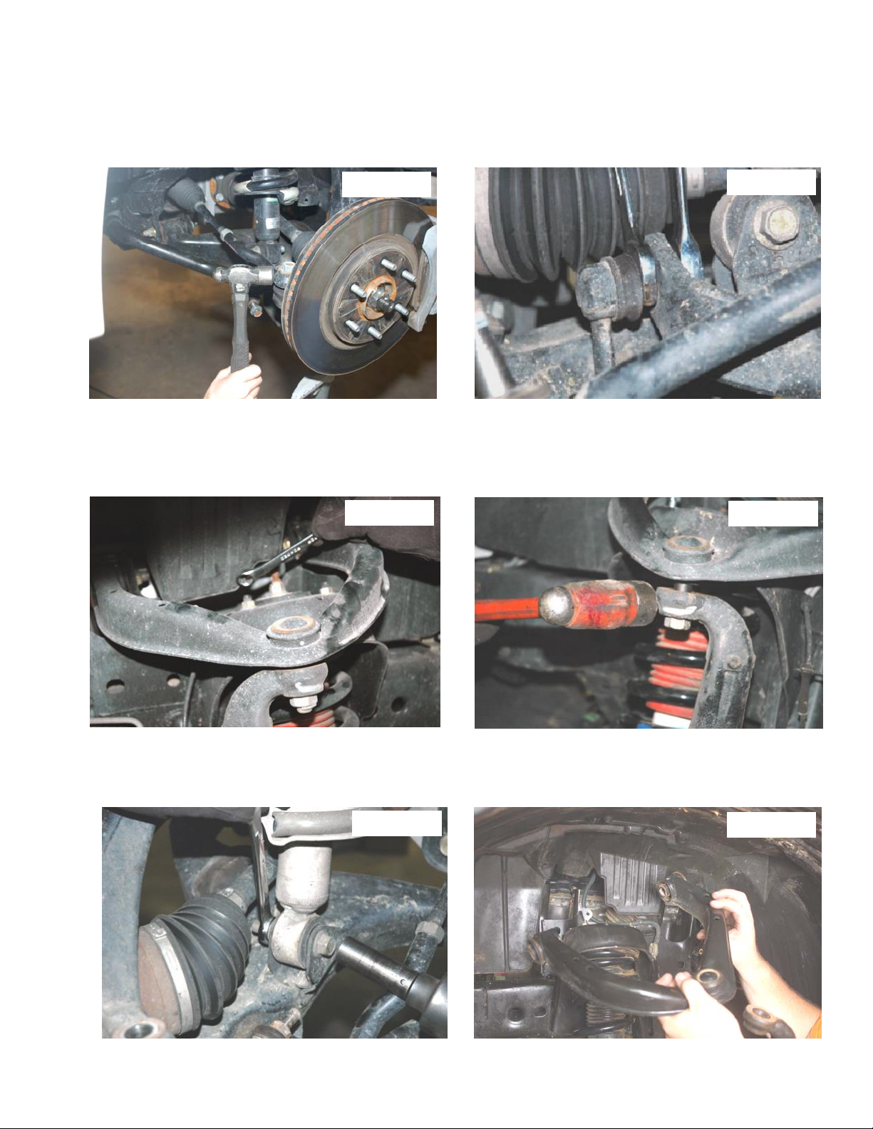
3. Using 22mm socket remove the nut from the steering linkage. Using a hammer hit on the side of the knuckle as
shown, and remove the linkage from the knuckle. Push linkage forward to make room for installation. Retain factory
hardware See Photo 1.
4. Using a 17mm wrench, remove the sway bar nuts from the sway bar as shown in Photo 2 and the axle allowing the
sway bar to drop.
Photo 1
5. Using a 14mm socket, remove the strut nuts on the upper strut tower that holds the assembly in place. See Photo 3.
.
One nut can be left on the upper bolts to hold the strut in place
6. Remove cotter pin from the upper control arm ball joint nut. Place jack stand under the knuckle for support. Using 22
mm socket remove nut. Using a hammer hit the knuckle as shown to allow the ball joint to separate from the upper
control arm See Photo 4. Do not allow the knuckle to pull out far enough that it pulls the shaft out of the differential.
Photo 3
Photo 2
Photo 4
7. Using a 19mm socket and wrench, remove the strut bolt from the lower control arm and remove the strut assembly
from the vehicle. Retain the factory lower bolt for reassembly. Note the direction of the bolt for reassembly. See
Photo 5.
8. Remove the upper control arm as shown in Photo 6 using a 19mm wrench. Retain the factory hardware for reuse.
Photo 5
Photo 6
Page 3
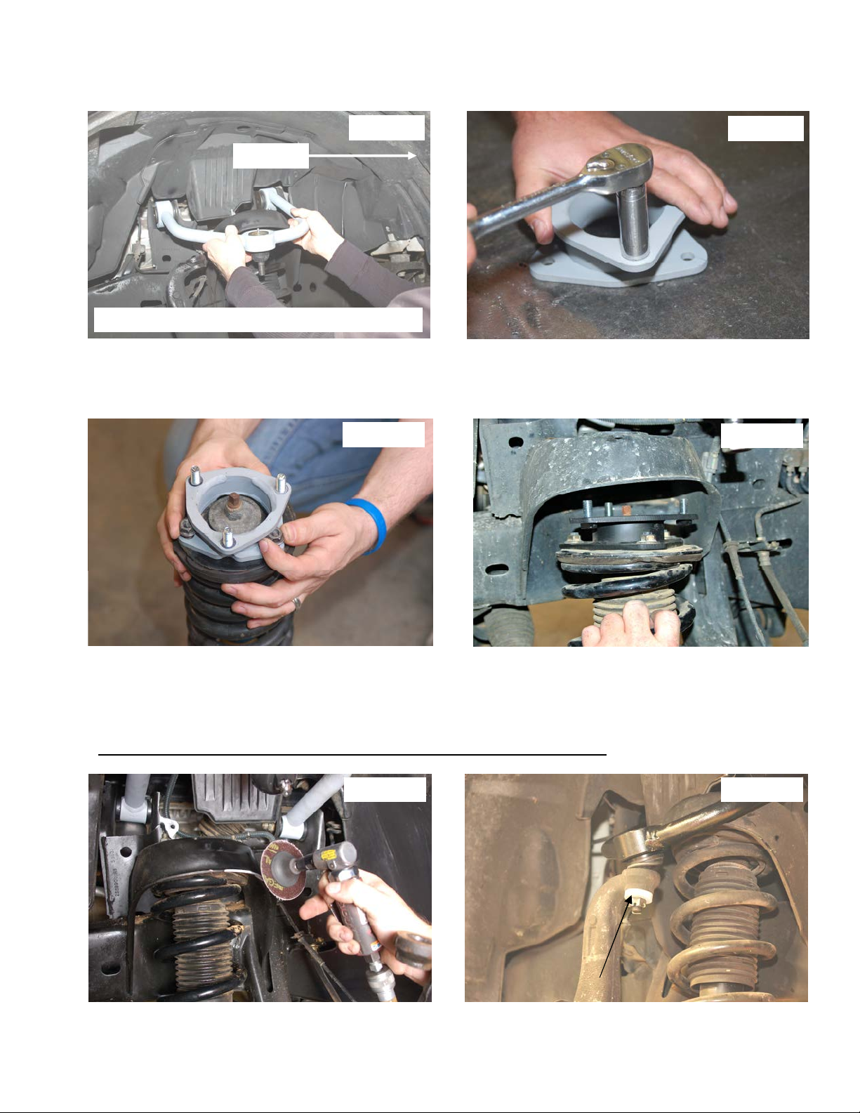
9. Grind the tabs on the inner side of the control arm pockets to allow the new control arms to be installed. Failure to
complete this task will not allow the new control arms to be installed.
10. Install the control arms in the factory location with the factory hardware. See Photo 7. Do not tighten at this time.
11. Locate the supplied 3/8” stud extensions. Using a 9/16” socket snug self clinching stud in the new spacer as shown
in Photo 8. The stud should clinch with about 35-45 ft/lbs of torque. Do not over torque the nut.
Photo 7
FRONT
PASSENGER SIDE SHOWN
12. Install the new strut spacer on the strut using factory hardware and a 14mm wrench. See Photo 9.
13. Install the strut assembly into the strut tower and secure with the supplied 3/8” nuts & lock washers. Tighten using a
.
See
9/16 wrench
14. Install the lower strut bolt in the original position that it was removed. Torque to factory specs using a 19mm wrench.
Photo 10.
Photo 9
Photo 8
Photo 10
15. On some vehicles it may be necessary to trim the upper strut tower to allow clearance for the ball joint. To check,
pull down the control arm to check if the ball joint can pass the upper strut tower. If not grind the upper strut tower to
allow for the arm / ball joint to pass the tower. See Photo 11.
15. Using a floor jack, raise the lower control arm and connect the upper ball joint on the upper control arm to the spindle
and install the supplied thick ball washer with supplied castle nut. See Photo 12. Install the cotter pin in the bal joint.
NOTE: The thick washer must be installed to properly engage the castle nut.
16. Using a 22mm socket reinstall the steering linkage nut and cotter pin.
Photo 11
Photo 12
Page 4
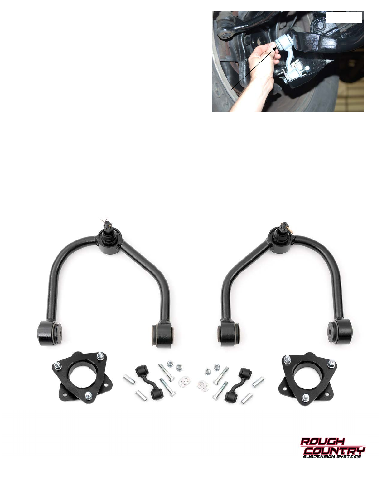
17. Install the supplied sleeves in the sway bar link bushings
and install on the sway bar and the axle with the supplied
12mm x 65mm bolts and lock nuts. NOTE: The washer will
install on the upper sway bar link as shown on the head
of the bolt. See Photo 13. Tighten using a 18mm & 19mm
wrench.
18. Repeat steps 3-16 on opposite side of vehicle.
19. Install the wheels / tires. Jack up the vehicle and remove
the jack stands. Lower the vehicle to the floor and torque all
bolts to factory specifications including upper control arms
20. After the vehicle has been lowered to the ground and using
17 mm wrench, reinstall sway bar links using factory
hardware. Torque to factory specs.
1. Check all fasteners for proper torque. Check to ensure there is adequate clearance between all rotating, mobile,
fixed and heated members. Check steering for interference and proper working order. Test brake system.
2. Perform steering sweep. The distance between the tire sidewall and the brake hose must be checked closely. Cycle
the steering from full turn to full turn to check for clearance. Failure to perform inspections may result in component
failure.
3. Re torque all fasteners after 500 miles. Visually inspect components and re torque fasteners during routine vehicle
service.
Post Installation
Photo 13
KIT CONTENTS
 Loading...