

Page 1

USER'S MANUAL
On-Grid PV Inverter
Series: RITxK(x=5,6,8,10,15,20,30,40,50,60)
USERS MANUAL
1
Page 2

INSTALLATION,OPERATION AND REPAIR MANUAL
About Rotosol
Rotosol solar (Division of Rotomag Motors and Controls Pvt. Ltd., located Near Anand,Gujarat,India .,
which is specialized in manufacturing of solar PV inverters.
Rotosol is dedicated to providing perfect power conversion and control solutions for solar power generation
installations , manufacturing and marketing of solar PV inverters. Rotosol possesses the first-class
production equipment . Rotosol provide all kinds of high-quality and reliable grid-connected solar inverters
and energy system solutions to satisfy the consistently increasing demands for global energy.
The newly designed PV Inverter features itself with full load high efficiency, high reliability and user-friendly
interface. The maximum conversion efficiency of our inverter is up to 98%. A user-friendly installation &
interface, professional industrial design, and design for reliability mechanism, give the Inverter Family a
competitive edge for customers from all regions.
As a customer-oriented company, Rotosol is always trying to improve product and enhance customer
satisfaction. High quality with customer satisfaction is the Goal of Rotosol , not just in product quality control,
but also in quality of service and support. Rotosol is able to help customers reduce energy consumption and
carbon dioxide emissions by leading green solutions.
2
Page 3

CONTENTS
1. About This manual
1.1Scope of Validity.................................................................................................................................. 4
1.2TargetGroup........................................................................................................................................... 4
1.3Additional Information........................................................................................................................4
2Safety Instructions
2.1 Safety Precautions..............................................................................................................................5
2.2 Explanations of Symbols................................................................................................................... 6
3 Unpacking
...............................................................................................................................................................
3.1 Assembly Parts...................................................................................................................................7
3.2 Identifying the Inverter...................................................................................................................... 8
4 Mounting
..................................................................................................................................................................
4.1 Safety................................................................................................................................................. 9
4.2 Selecting the Appropriate Mounting Location...................................................................................9
4.3 Mounting the Inverter with Wall Mounting Bracket........................................................................11
5 Electrical Connection
Notes:
...........................................................................................................................................................................
5.1 Overview of the Connection Area................................................................................................... 13
The following figures show the assignment of the individual connection areas on the bottom of
theInverter..............................................................................................................................................13
5.2 Connection to the Public Grid (AC)................................................................................................ 13
5.3 Connection to the PV Generator (DC).............................................................................................16
6 System Diagram
7 Operation
..............................................................................................................................................................
7.1 Overview of Control and Displays........................................................................................................ 23
7.2 Commissioning.................................................................................................................................... 24
7.3LED Display........................................................................................................................................ 24
7.4LCDDisplay........................................................................................................................................25
8 Trouble Shooting
9 Inverter Inspection and Repair
9.1LCDcannotDisplay..............................................................................................................................34
9.2LCDdisplay FaultCodes....................................................................................................................... 34
9.3RepeatCountdown, cannot generation......................................................................................................35
9.4ACcircuit breakertrip............................................................................................................................ 35
9.5MonitoringFault...................................................................................................................................35
9.6Problem During Inverter Generation.........................................................................................................35
9.7 PowerComponents Inspection(without DC power supply)......................................................................36
9.8 MOSFET Driver Inspection(for 5th generation models).......................................................................... 41
9.9 Inverter FrequentlyTrippingDue to Grid Fluctuation..............................................................................41
10 Contact
Annex Warranty Terms (Overseas)
...............................................................................................................................................................
............................................................................................................................................
..................................................................................................................................................
....................................................................................................................................
...............................................................................................................................................
.................................................................................................................................................
.................................................................................................................
............................................................................................................
4
5
7
9
12
12
21
23
30
34
43
43
3
Page 4

1. About This manual
1.1 Scope of Validity
This manual describes the installation, commissioning, operation and maintenance of the following on-grid
PV inverters produced by Rotosol:
Commercial Systems & Power Plants 5-60KW
RIT5K , RIT6K, RIT8K, RIT10K, RIT15K, RIT20K, RIT30K, RIT40K, RIT50K, RIT60K
Please keep this manual all time available in case of emergency.
1.2 Target Group
This manual is for qualified personnel. The tasks described in this manual must only be performed by
qualified personnel.
1.3 Additional Information
For more information please go through the website www.rotosol.solar
4
Page 5

2 Safety Instructions
2.1 Safety Precautions
1. All work on the inverter must be carried out by qualified electricians and ensure that children can
not access to the equipment.
2. The device may only be operated with PV generators. Do not connect any other sources of energy
to the device.
3. This PV generator and inverter must be connected to the ground in order to reach maximum
protection for property and persons.
4. Do not touch cover until 3 minutes after disconnecting all sources of supply. This is because the
charge stored in capacitors may result a risk of electric shock.
5. The enclosure of Inverter can become hot during operation. To reduce the risk of injury, do not
touch the cover, heat sink at the back of the PV-lnverter or nearby surfaces while Inverter is
operating.
6. Do not use the equipment for purposes other than those described in this manual.
7. Both the inverter and associated transport packaging are mainly made of recyclable raw materials.
Please ensure that the used device and any relevant accessories are disposed of in accordance
with applicable regulations.
8. Packed with damping EPE and carton, Rotosol inverter should be placed upwards and handled with
care in delivery. Pay attention to waterproof.
9. Alternative uses, modifications to the inverter not recommended by Rotosol or the installation of
components not sold by Rotosol void the warranty claims.
5
Page 6

2.2 Explanations of Symbols
6
Page 7

3 Unpacking
Object
Quantity
Description
Object
Quantity
Description
A1Solar inverter
B1Wall mounting bracket
C1User manual
D1Certificate of inspection
E1Installation diagram
F
1
Notice for installation
G
1
Warranty card
H
1
RV5.5-6 terminal
I
3
Plastic Expansion Tube
J
3
Tapping screw
K
1
Security screw
L
1
Screwdriver for security screw
M
2sets
DC plug connector
N4Screw
O
1
Waterproof Junction Box
P
4
Terminal
3.1 Assembly Parts
Please check the delivery for completeness and any visible external damage. Contact your dealer at once
if anything is damaged or missing.
Assembly parts are as listed below:
7
Page 8

3.2 Identifying the Inverter
You can identify the inverter by the type label. Information such as serial number (Serial No.) and
model name of the inverter, as well as the device's technical parameters are specified on the type label.
The type label is on the right side of the enclosure.
8
Page 9

4 Mounting
4.1 Safety
DANGER!
Danger to life due to potential fire or electric shock.
Do not install the inverter near any inflammable or explosive items. The inverter will be directly connected
with high voltage power generation device. The installation must be performed by qualified personnel only
in compliance with national or local standards and regulations.
CAUTION!
Danger of burn injuries due to hot enclosure parts.
•Install the inverter so that it cannot be touched inadvertently.
Risk of injury due to the heavy weight of the inverter.
• Take the inverter's weight into account for mounting. (Weight of inverter refers to chapter 8.)
4.2 Selecting the Appropriate Mounting Location
Consider the following points when selecting where to install:
The mounting method and location must be suitable for the inverter's weight and dimensions.
The inverter must be installed in the solid walls ,such as brick walls or concrete walls in case of
vibration noise or inverter falling off.
The installation site should be clearly visible and can be safely into without aids such as scaffold.
For the convenience of checking the LCD display and possible maintenance activities, please
install the inverter at eye level.
The altitude of installation site should be below 2000m,more than 2000m above the sea level will
cause derating.
The ambient temperature of installation site should be between -20 °C and +55 °C (between -4 °F
and 131 °F).
Install the inverter directly exposing to strong sunshine is not recommended, the excess heating
9
Page 10

might lead to power reduction.
Leave enough effective space around the inverter for better ventilation.
• Vertical installation, wiring area must be downside, lateral installation is not allowed; in backward
tilted installation, tilt angle should not exceed 30 degrees; Forward tilted, horizontal or inverted
installation is not allowed.
10
Page 11

4.3 Mounting the Inverter with Wall Mounting Bracket
1. Use the wall mounting bracket mark the drilling position and drill the holes for the screws.
2.Fix the wall mounting bracket with the equipped self-tapping screw.
3. Hang the inverter to the mounting bracket and ensure the slot is fitted on the bracket.
4. Check to ensure the inverter is correctly seated. Make sure to lock it with the security
screws. (See the figure below.)
11
Page 12

5 Electrical Connection
Notes:
1. Electrical installation & maintenance shall be conducted by licensed electrician and shall comply
with local Wiring Rules.
2. After the inverter has been installed in its fixed position, the electrical connection to the unit can be
established.
3. Make sure Max. Open Voltage and short-circuit current of the each PV strings accord with the Spec.
4. Choose the appropriate cable width for AC/DC wire. The cross sectional area of DC input conductor
lead should be 4mm2PV wire, that of AC output conductor should also be 4mm2cooper wire, and
that of external ground conductor should be 4mm2cooper wire.
5. On both sides of inverter to the grid and PV array, there must be between circuit breaker and surge
protector, and during inverter electrical connections, circuit breakers on both sides should be
disconnected to prevent electric shock.
6. To connect the inverter,the AC and DC sides must be disconneted from all power sources and
secured against being inadvertently swithced back on.
7. Before connecting the inverter to PV arrays and public grid, make sure the polarity is correct.
12
Page 13

5.1 Overview of the Connection Area
Object
Description
a
DC connectors ( + ) for connecting the PV strings
b
DC connectors ( − ) for connecting the PV strings
c
WiFi/RS485 Communication Waterproof Connector
d
Waterproof Junction Box, AC connection
e
DC Switch
The following figures show the assignment of the individual connection areas on the bottom of theInverter.
5.2 Connection to the Public Grid (AC)
5.2.1 Conditions for Connection
CAUTION!
Unit Disconnection From Load
Disconnect the circuit breakers and switches of inverters AC and DC sides.
5.2.2 Connection to Public Grid (AC)
13
Page 14

Measure the grid voltage to make sure within the permissible range. Disconnect the circuit
1. Disconnect the DC and AC breaker, DC switch in the"OFF"state..
2.Disconnect the DC and AC breaker, DC switch in the"OFF"state.
3. Assembly yellow-green Ground wire RV5.5-6 terminal, and connect to one ground terminal.
breaker between the inverter and the grid.
14
Page 15

4.Prepare AC cable(Φ4mm2 or bigger), stripping length is 14±0.5mm. Connect the cable with
terminals.
5. Run the cable harness with the pressed terminals through the junction box and insert the black
cable harness, L1, L2 and L3 into the caps of N, W, V and U as shown in the system connection
diagram. Tighten the screws.
15
Page 16

6. Close junction box and tight the screws
5.3 Connection to the PV Generator (DC)
CAUTION!
Unit Disconnection From Load
Disconnectcircuit breakers and switches on bothAC and DCsides
5.3.1 Conditions for the DC Connection
The connected PV modules must meet following requirements
-Sametype
-Samemodel
-Identical alignment
- Identical tilt
The following limit values at the DC input of the inverter must not be exceeded (connecting to a higher
16
Page 17

voltage will destroy the device):
Type
Maximum input voltage [Vd.c]
Maximum input current [Ad.c]
RIT5K
1000
11x2
RIT6K
1000
11x2
RIT8K
1000
11x2
RIT10K
1000
11x2
RIT15K
1000
22+11
RIT20K
1000
22x2
RIT30K
1000
33x2
RIT40K
1000
40x2
RIT50K
1000
36x3
RIT60K
1000
40x3
5.3.2 Assembling the DC Plug Connector
In order to connect to the inverter, all connection cables of the PV modules must be equipped with the DC
plug connectors provided. You will find the necessary DC plug connector for DC connection in the package.
To assemble the DC plug connectors, proceed as detailed below. Ensure the plug connectors have the
correct polarity.
The plug connector in DC side includes male and female as blow.
Please note that the sizes of metal connecting tubes are different. The bigger one is for female connector
and the smaller one is for male connector.
17
Page 18

Assembly Instructions:
♦ Prepare the DC wire to connect the positive and negative DC arrays. Stripping length is 12~15mm,
sectional area is 4 mm2as below.
♦ Insert the DC wire to metal connecting tube. Make sure all line heads are in the connecting tube as
picture blow.
♦ Use crimping pliers to fasten the metal connecting tube and copper wire. Make sure the harness will not
18
Page 19

fall off, see picture below.
♦ Insert the assembled cable into male/female connector. A "chick" sound can be heard when
connecting correctly. Then tighten the cap. Refer to the picture below.
5.3.3 Connecting the PV Generator (DC)
DANGER!
Danger to life due to high voltage in the inverter.
• Before connecting the PV generator, ensure that the AC&DC circuit breaker is switched off.
Notes:
1. Make sure that you have disconnected circuit breakers and switches on both DC and AC sides.
2. Check the connection cables of the PV modules for correct polarity and that the maximum input
voltage of the inverter is not exceeded.
3. Check the DC plug connector for correct polarity and well connected.
19
Page 20

Plug the DC plug connectors into DC terminals on Inverter.
The inverter DC input is equipped with two groups(DC-A and DC-B) of connecting sockets for DC input ,
and each group contains two pairs of connecting sockets (DC+ and DC-). Make sure at least one pair of
DC terminal in each group is connected with PV array in installation,and group A and B must be
connected with two arrays separately but not with one array,see picture below.
20
Page 21

6 System Diagram
Type
Max AC Current [A]
Rate current of AC breaker[A]
RIT5K
8.5
16
RIT6K
10.5
16
RIT8K
13.5
20
The typical connection diagram for the entire PV system is shown in the following figure.
1. PV Panel: Provide DC power to inverter
2. Inverters: Converts DC (Direct Current) power from PV panel(s) to AC (Alternating Current) power.
Because Inverter is grid-connected, it controls the current amplitude according to the PV Panel
power supply. Inverter always tries to convert the maximum power from the PV array.
3. QF1/QF2 Breaker: The current per DC string does not exceed 25A.
4. QF3 Breaker: Refer to the following table to choose the AC breaker.
Refer to the following table to choose the AC breaker.
21
Page 22

RIT10K
17
25
RIT15K
27
32
RIT20K
32
40
RIT30K
45
63
RIT40K
60
100
RIT50K
75
100
RIT60K
90
125
5. LPS: Lightning protection system, refer to the fol owing options:
AC side, nominal discharge current 20KA, second grade lightning protection, protection voltage 2.5KV
DC side, nominal discharge current 20KA, second grade lightning protection, protection voltage 3.2KV
6. The wiring distance between the inverter and the distribution box should be at least 5 meters.
7.Utility: Referred to as "grid" in this manual, i.e. the media your electric power company provides power to
your place. Please note that Inverter can only be connected to low-voltage systems (namely, 220/230Vac,
50/60Hz).
22
Page 23

7 Operation
Product Overview
7.1 Overview of Control and Displays
There are four function keys on the front panel: UP, DOWN, ESC, ENT. The keypad is used for:
Up and Down keys: Scrolling the displayed parameter, or modify the adjustable parameters; Esc and Ent keys:
Cancel orEnter.
23
Page 24

7.2 Commissioning
Sign
Color
Instructions
POWER
Green
On: Power On
COM
Green
On: Normal Operations and Feed the utility grid.
FAULT
Red
Flash: Check wiring
After completing of the mechanical and electrical installation, the inverter could be put into operation.
1. Switch off DC and AC side circuit breakers and switches.
2. Wait until the screen is on and set up grid connection standard. (Please refer to 7.4.1 for specific
operations)
3. The inverter starts up and feed into the utility grid automatically when all the necessary conditions
of normal operation for the inverter is fulfilled.
4. Check whether the display and LEDs are indicating a normal operating state.
7.3 LED Display
Three LED lights are assembled on the inverter, COM,POWER, FAULT. When DC andAC power are normaland
the inverters startsup,the POWER LED turns on. Whentheinverter is operating andfeedelectricityinto the utility grid
normally,theCOM LED turnson. When thereis faulty in the PVSystem orinverter,theFAULT LED flashes,andthe faulty
code willbe shown on LCD Screen.
POWER LED (Green)
POWER LED turns on when DC voltage reaches the start-up voltage and turns off when it falls below a
certain value. POWER LED is on represents inverter is active and so is the inverter control system. If POWER
LED is off, inverter cannot be normally started up.
Under normal operation conditions, when light is sufficient, inverter connects to the grid and generates in
the morning and stops after dark. This procedure may repeat several times in one day, especially in
morning and at night. It is a normal working phenomenon but not a wrong signal.
COMLED(Green)
TheCOMLEDturnsonwhentheinverterstart feedelectricity intogrid.Andthe COMLEDisoffwhentheinverter is standby.
FAULTLED(Red)
Red FAULT LED turns on means the on-grid generation is stopped due to some faults. Please wait 10
24
Page 25

minutes to be sure whether the fault is temporary. If yes, inverter will automatically restart again. If not,
contact after-sales personnel.
7.4 LCD Display
Inverter will start up automatically with enough DC voltage provided by PV array. When starting up (POWER
LED is on), it shows "Rotosol" on LCD in front of the inverter.
The inverter will delay 1 second and automatically jump to the System Checking Interface.
7.4.1 First Boot Setting
First turned on power, the inverter will delay 1 second and automatically jump to the reminder interface to
set country.
Press Ent to country and standard setting interface. Press UP and DOWN to show countries. Choose
corresponding country and standard and press Ent.For example installed in India, please choose
Country setting completed, system will automatically jump to the reminder interface to set time.
25
Page 26

Press Ent to time setting interface. Press UP and DOWN to adjust number and press Ent. Set year, month,
Display
Description
Power
Current Output Power
IPV1/IPV2
DC Input Current in MPPT One/Two
VPV1 /VPV2
DC Input Voltage in MPPT One/Two
BUS+/BUS-
Voltage of BUS+/BUS-
Ia/Ib/Ic
AC output Current per phase
Ua/Ub/Uc
AC output Voltage per phase
FAC
AC Output Frequency
day, hour, minute and second one by one according to local time.
7.4.2 Main Interface
When time setting is completed, press Ent to exit and system will enter into the main interface as below.
The LCD will automatically enter into the main interface after system checking when the inverter starts up
next time. Operation status and generation information of inverter will be show on the main interface
(Display Info),the current time will be shown in the last line.
Generation information interface scrolls every 3 seconds. Up and Down also can be used to select.
Items of generation information are as follows:
26
Page 27

Etoday
Total Generation Capacity today
Etotal
Total Generation Capacity
ETPV1/ETPV2
Total Generation Capacity today in MPPT One/Two
RunTim
Total Running Time Today
SumTim
Total Running Time
7.4.3 Query Interface
Dispay
Description
Standard
Country and standard setting
Case_Temp
Chasis temperature
ModleTemp
Power module temperature
Screenwriter
LCD temperature
Rated Power
Inverter rated output power
PG1Imp
The insulation resistance of positive pole in PV1
NG1Imp
The insulation resistance of negative pole in PV1
PG2Imp
The insulation resistance of Positive pole in PV2
Press Ent on main interface to view related information in query interface. Eight choosing items on the
query interface: System Info,Error Record,SET,Clear Record,Data & Time SER,RS485 Address,SN
Number,GridpowerCtrl. Press UP and DOWN to select the query item,press Ent to get in and Esc back to
main interface.
System Info
System Informationshows country standard and operation parameters.
UPand DOWN could beused to show the itemsof Systeminfo as follows:
27
Page 28

NG2Imp
The insulation resistance of negative pole in PV2
Error Record
Display
Description
Nub/Total
Fault sequence/Total faults number
E
Fault Code
ST
Fault starting time
ET
Fault Ending Time
In Error Record, it shows fault series number, the time fault happens, faulty code and error display. When fault
happens, FAULT LED turns on. "Trouble Shooting" in Chapter 9 is for users to refer to investigate and solve
the faults. Please contact after-sales if the problem stillexists.
Error Record Shows:
SET
Reset the inverter parameters by selecting SET. Passwords are needed for the setting. Which only can be
operated by after sales personnel to make sure the safety and normal operations of the inverter.
Clear Record
Clear inverter's Error Record and Run records. Passwords are needed for the setting,which only can be
28
Page 29
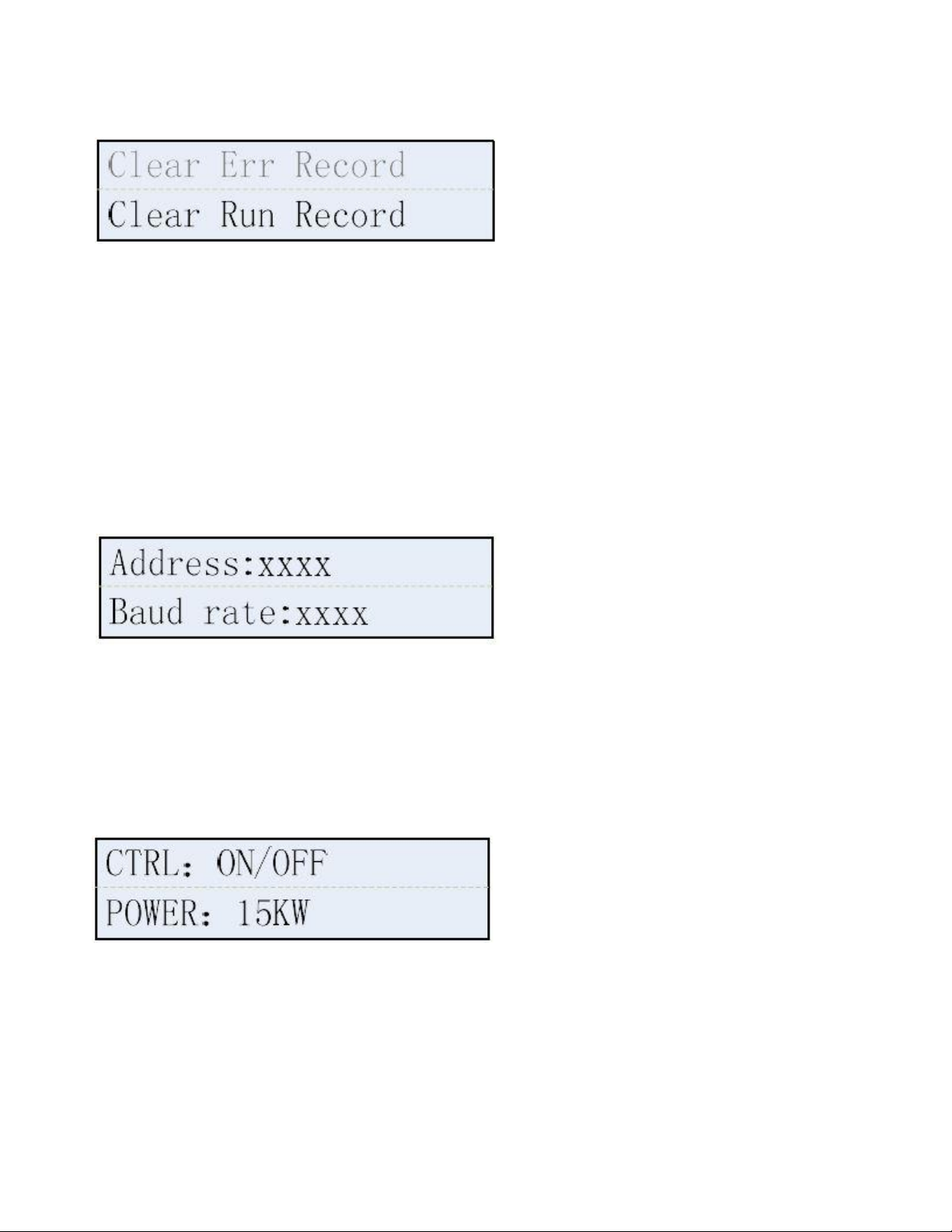
operated by after sales personnel to make sure the safety and normal operation of the inverter.
Date & Time SET
Press Ent to Date and Time setting interface.Press UP and DOWN to adjust number and press ESC go to next step.
Set year,month,day,hour and minute one by one according to local time. Press ENT save and back to main interface.
RS485Setting
485 address shows communication address and baud rate. Press ENT to enter communication address setting
interface;press UPand DOWN to change values;Press ENTto confirm.
SN It shows inverter's serial Number
SetPowerCtrl
This item is for setting grid-connecting power limitation. Press ENT to enter control selection interface. Press UP and
DOWN to choose start-up or use forbidden,then press ENT to confirm;Press ENT to enter power limitation setting
interface. Press UPand DOWN to set limitationvalue,then press ENT to confirm.
7.4.4 LCD Back light Control
The back light of LCD will automatically turn off after 5 minutes,and LCD will automatically turn off after 10 minutes to
saving-electricity mode. Press any key to turn on the LCD.
29
Page 30

8 Trouble Shooting
Error display
Possble causes
Corresponding measures
EepromErr
1.Unstable PV Input voltage
2. Machine Failure
1.After PV input voltage is stabilized, the machine will
automatically restart.
2. Please contact with local dealer if error remains the
same after several reset.
GFCI.Err
1.PV(+) or PV(-) earthing
2.Machine Failure
1.Check PV(+) and PV(-)ground impedance, make sure
impedance is more than 2M Q.
2.Please contact with local dealer if error remains the
same after several reset.
GridF.OutLim
Electricity grid fluctuations
1. After electricity grid returns to
normal,the machine will automatically restart.
Electricity grid Frequency out
of range
2.Please contact with local dealer if error remains the
same after several reset.
Machine failure
GridV.OutLim
1. Off Phase
1.Disconnect the input/output switch, check the ACside wiring and reset the plug to rule out bad
2.Electricity grid Phase/line
voltage overload
2.After electricity grid returns to normal,
the machine will automatically restart.
3.electricity grid Voltage
unbalance
3.Please contact with local dealer if error remains the
same after several reset.
IntFaultA
Machine failure
Please contact with local dealer if error remains the
same after several reset.
IntFaultB
1.PV input voltage is too high
1..Adjust the panel configuration to lower the input
voltage.
2.Electricity grid abnormal
2.After electricity grid returns to normal,
the machine will automatically restart.
3.Bus hardware overvoltage
fault
3.Please contact with local dealer if error remains the
same after several reset.
IntFaultC
Electricity grid abnormal
1.After electricity grid returns to normal, the
machine will
In most situations, the inverter requires very little service. However, if inverter is not able to work perfectly,
we recommend the following solutions for quick troubleshooting.
30
Page 31

Unbalanced current fault
automatically restart.
2.Please contact with local dealer if error remains the
same after several reset.
IntFaultD
1.Electricity grid abnormal
1.After electricity grid returns to normal, the
machine will automatically restart.
2.Software over current fault
2.Please contact with local dealer if error remains the
same after several reset.
IntFaultE
1.Electricity grid abnormal
1.After electricity grid returns to normal,
the machine will automatically restart.
2.Hardware over current fault
2.Please contact with local dealer if error remains the
same after several reset.
IntFaultG
1.Electricity grid abnormal
1.After electricity grid returns to normal,
the machine will automatically restart.
2.DCI too high
2.Please contact with local dealer if error remains the
same after several reset.
IntFaultJ
Relay failure
Please contact with local dealer if error remains the
same after several reset.
IntFaultK
1.Electricity grid abnormal
1.After electricity grid returns to normal,
the machine will automatically restart.
2.Bus differential fault
2.Please contact with local dealer if error remains the
same after several reset.
IntFaultL
1.Electricity grid abnormal
1.After electricity grid returns to normal,
the machine will automatically restart.
2.Low Bus voltage fault
2.Please contact with local dealer if error remains the
same after several reset.
IntFaultM
1.Electricity grid abnormal
1.After electricity grid returns to normal,
the machine will automatically restart.
2.High Bus voltage fault
2.Please contact with local dealer if error remains the
same after several res
IntFaultN
Internal hardware fault
Please contact with local dealer if error remains the
same after several reset.
IntProtectA
Offset current protection
Please contact with local dealer if error remains the
same after several reset.
IntProtectB
Relay protection
Please contact with local dealer if error remains the
same after several reset.
IntProtectC
Over current protection
Please contact with local dealer if error remains the
same after several reset.
31
Page 32

IntProtectD
l.PVside high current
1.Adjust the panel configuration to lower the input
current.
2.Boost over current protection
2.Please contact with local dealer if error remains the
same after several reset.
IntProtectE
1.Electricity grid abnormal
1.After electricity grid returns to normal,
the machine will automatically restart.
2.Soft start overtime protection
2.Please contact with local dealer if error remains the
same after several reset.
IntProtectF
When direct current is at
low
Please contact with local dealer if error remains the
same after several reset.
voltage, Soft start
overtime protection.
IntProtectG
Bus voltage differential
protection
Please contact with local dealer if error remains the
same after several reset.
IntProtectH
Low Bus voltage protection
Please contact with local dealer if error remains the
same after several reset.
IntProtectl
High Bus voltage protection
Please contact with local dealer if error remains the
same after several reset.
IntProtectl
Inverter bridge protection
Please contact with local dealer if error remains the
same after several reset.
IntProtectK
Bus hardware overvoltage
Please contact with local dealer if error remains the
same after several reset.
protection
IntProtectL
Power module protection
Please contact with local dealer if error remains the
same after several reset.
IntProtectM
1.electricity grid unbalance
1.After electricity grid returns to normal,
the machine will automatically restart.
2.Unbalanced current protection
2.Please contact with local dealer if error remains the
same after several reset.
IntProtectN
1.Electricity grid abnormal
1.After electricity grid returns to normal,
the machine will automatically restart.
2.Hardware
32
Page 33

overcurrentprotection
2.Please contact with local dealer if error remains the
same after several reset.
IntProtectO
MCU protection
Please contact with local dealer if error remains the
same after several reset.
IntProtectP
Frequency fault protection
Reset grid frequency in accordance to local grid
standard
IntProtectQ
DCI too high protection
Please contact with local dealer if error remains the
same after several reset.
IntProtectR
DCI offset protection
Please contact with local dealer if error remains the
same after several reset.
IntProtectS
Voltage offset protection
Please contact with local dealer if error remains the
same after several reset.
IntProtectT
PV over current protection
Please contact with local dealer if error remains the
same after several reset.
IntProtectU
Internal hardware
abnormal
protection
Please contact with local dealer if error remains the
same after several reset.
IsolationErr
1.PV(+) or PV(-) earthing
2.Lightening
3.Machine failure
1.Check PV(+) and PV(-) ground
impedance, make sure impedance is more
than 2MQ.
2.Please contact with after-sales if error remains the
same after several reset.
PV. Reverse
1.PV polarity reverse protection
1.Turn off input/output switch,check if pv polarity is
correct or
2.Machine failure
not, for troubleshooting.
2.Please contact with after-sales if error remains the
same after
PVVoltOver
PV The input voltage is too high
1. Adjust the panel configuration to lower the input
voltage.
2.Please contact with local dealer if error remains the
same after several reset.
SPICommErr
SPI communication error
Please contact with local dealer if error remains the
same after several reset.
TempOver
1.The machine is exposed to
sun.
1. Lower machine surrounding temperature or move it
to a lower
2.the ambient temperature is too
temperature place.
33
Page 34

high
2. Remove foreign matter.
3. The heat sink or fan blocked
by foreign matter
3.Please contact with local dealer if error remains the
same after several reset.
4.Machinefailure
TempSensorErr
Abnormal temperature sensor
Please contact with local dealer if error remains the
same after several reset.
ExtFanErr
1.Fan blocked by foreign matter
1.Remove foreign matter.
2.Machine failure
2.Please contact with local dealer if error remains the
same after several reset.
IntFanErr
Internal fan fault
Please contact with after-sales if error remains the
same after several reset.
Restart: Disconnect input and output switches in order, reconnect them after LCD and indicating
lights go off.
If there is no display on the LCD, please check both AC and DC wiring.
If the input DC voltage is higher than start up voltage, the inverter still doesn't work, please call local
service.
If it is intended to replace the cable or open the enclosure lid, please call our service.
Under the low light conditions, the inverter may continuously start up and shut down. It is due to
insufficient power generated to operate the control circuits.
9 Inverter Inspection and Repair
9.1 LCD cannot Display
a. check DC wiring is ok.
b. PV array’s ‘+’ and ‘-’ is right connect with inverter’s DC input connector;
c. check DC switch is at ‘ON’ position;
d. check PV array’s voltage within right range by use multi meter.
9.2 LCD display Fault Codes
9.2.1 Grid Fault
a. check safety code or country code is correct (all of the models provide to Rotomag is India);
b. check grid’s voltage and frequency is within setting range (for the place where the real range is out of
setting, please contact us for detailed setting);
34
Page 35

c. check all of AC wiring connection point is well connected.
9.2.2 Isolation Fault
Check PV array have leak current.
9.2.3 Input DC bus voltage High
9.2.3.1 check DC input voltage is within inverter’s input range;
9.2.3.2 check all of AC wiring connection point is well connected.
9.3 Repeat Countdown, cannot generation
9.3.1 check the resistance between PV(+) and ground, PV(-) and ground bigger than 2MΩ;
9.3.2 check PV array’s output voltage is correct.
9.4 AC circuit breaker trip
9.4.1 check circuit breaker’s capacity is suitable with inverter’s maximum output power;
9.4.2 for the system installed with leak current sensor circuit breaker,
a. trip during cloudy /rainy day, change with higher capacity of current senor breaker;
b. check if the PV panel’s frame is too close with ground or roof , exit the leakage current;
c. check if the PV DC wiring have the leakage current.
9.5 Monitoring Fault
9.5.1 cannot search wifi single of inverter,
before open the cover of monitoring card, please make sure the inverter is generation;
a. check the cable wiring is well connected;
b. the LED on the monitoring card is flash;
c. Measure the voltage of signal cable is correct(DC 5V)
9.5.2 WIFI cannot upload data
connect inverter’s WIFI with smart-phone, and go to 10.10.100.254 website via smart-phone’s explorer.
a. check if the inverter’s WIFI card have been assigned IP address;
b. check the inverter’s power generation date or serial information displayed through the web page.
c. check the WIFI signal is strong enough.
9.6 Problem During Inverter Generation
9.6.1 Power generation lower than expect
a. check if the panel surface need to be clean;
b. check if the panel have shading problem;
c. check all of the DC wiring is well connected;
d. check if the wiring connection point have been oxidized;
e. check the cable used for DC and AC is right size, and the length of the cable not excess the recommend
length.
35
Page 36

9.6.2 Generation difference between two or among three MPPT channels.
a. check each MPPT channels’ input voltage not higher than 30%;
b. check PV array’s tilt and azimuth angle is the same;
c. check if the PV array have shading problem.
9.6.3( Grid line Voltage Fault) Fault Report
a. due to the grid fluctuate, if the fault report occasionally, you can ignore this fault report, and the inverter
could recover automatically after the grid back to the normal;
b. if this fault frequently report, we recommend to upgrade the firmware of DSP.
9.6.4 E17(Grid Voltage Fault) Fault Report
a. check the safety/country code is correct;
b. check all of the AC wiring point is well connected;
c. measure the AC voltage is within normal range;
d. re-setting the AC output range(maximum volt. Is 519Vac).
9.6.5 E29(M Grid Freq Fault) Fault Report
a. check the safety/country code is correct;
b. check all of the AC wiring point is well connected;
c. measure the AC frequency is within normal range;
d. re-setting the AC frequency range(49.0 ~ 51.0Hz).
9.6.6 Other Fault Report
9.6.6.1 Inverter report the same Fault Code during the same time of the day
Check if the AC output point nearby have the big power load. When the load start, the grid voltage or
frequency will be affect.
9.6.6.2 Inverter report over current or over voltage fault code
a. check the cable used for DC and AC is right size, and the length of the cable not excess the recommend
length;
b. check local load consumption is low, grid voltage is high;
c. switch the output line to the lower voltage phase if possible.
9.6.6.3 Circuit breaker trip during frog, cloudy and rainy day
check the resistance between PV(+) and ground, PV(-) and ground lower than 2MΩ.
9.6.6.4 Daily generation date cannot count from zero
check the date and time setting is correct.
9.7 Power Components Inspection(without DC power supply)
9.7.1 Power diode
a. single diode
b. dual-diode
36
Page 37

Switch to the diode position of multimeter, please notice the ‘+’ and ‘-‘. The normal value is 0.33~0.37V(‘+’
with ‘-‘), ∞ (‘-‘ with ‘+’). And specific value could compare with normal inverter. Value close to the zero or
bigger than normal range stands the diode is damaged.
For the 5thgeneration models(total 4 measure positions)
37
Page 38

38
Page 39

9.7.2 IGBT / MOSFET
a. IGBT
b. MOSFET
a. switch to the diode position of multimeter, and measure the value between Pin 3 and Pin 2, normal value
is 0.3~0.4V. Value close to the zero stands the component is damaged;
b. the normal resistance between Pin 2 and Pin 3 should be infinity(∞), value close to the zero stands the
component is damaged;
c. check if the short-circuit between Pin 1 and Pin 2, Pin 2 and Pin 3.
For the 5thgeneration models(total 8 measure positions)
39
Page 40

9.7.3 Component Position Number
Power Diode Position Number
5thGeneration Single MPPT
D1
5thGeneration Dual-MPPT
D9, D13, D30, D31
IGBT/MOSFET Position Number
5thGeneration Single MPPT
Q2, QA1, QA2, QA3, QB1, QB2, QB3
5thGeneration Dual-MPPT
Q2, Q4, QA1, QA2, QA3, QB1, QB2, QB3
40
Page 41

9.8 MOSFET Driver Inspection(for 5th generation models)
Remove the control board and control board mounting pad. Power the inverter with 100Vdc source and
wait about 15 seconds. Measure the voltage of all of the MOSFET Pin 1 and Pin 3 separately, the normal
driver voltage is -5Vdc. If the voltage abnormal, it stands the power PCB is damaged.
9.9 Inverter Frequently Tripping Due to Grid Fluctuation
9.9.1 Check the grid voltage with multimeter if voltage range goes below or beyond of -20% to +10% then
check the Vac.Min and Vac.Max setting in inverter by selecting SET menu as mention below.
9.9.2 Press enter key for two time and menu is open which shows Error record (Fig.1)and by up-down key
select the SET menu (Fig.2).
Fig.1 Fig. 2
41
Page 42

9.9.3 Select the SET menu by enter key and you will get the display as mention in Fig. 3 and Fig. 4.
Fig.3 Fig.4
9.9.4 Press enter key to set the voltge range and enter the password as shown in Fig.5.
Fig. 5
9.9.5 Adjust the voltage range of Vac.Min and Vac.Max by up-down key and set it at Vac. Max:450V and Vac. Min:339V as
shown in Fig.6 and Fig.7.
Fig.6 Fig.7
Note:- Display screen menu change according to rating of the Inverter.
42
Page 43

10 Contact
Please do not hesitate to contact us for any technical problems you have. Please be sure to provide the
following information in order to obtain necessary assistance:
Inverter type
Inverter serial number
Inverter SN Number
Customer Information
The contents of this manual are subject to change without further notice. For Rotosol latest product
information, please visit our website www.rotosol.solar
Rotosol Solar(Division of Solar – Rotomag motors and controls pvt ltd.)
www.rotosol.solar
ADD: 2102/3 & 4 ,Vitthal Udhyognagar
Near Anand, Gujarat – 388121 , India
Phone : +91-9227110023/24/25
E-MAIL: invert@rotosol.solar
Website : www.rotosol.solar
Annex Warranty Terms (Overseas)
Rotosol Solar(Division of Solar – Rotomag motors and controls pvt ltd.) Product Warranty Terms
1.Product Quality Standards and Warranty
Rotosol inverters comply with local safety regulations related to the national grid and grid
standards.
The inverter warranty is decided by Rotosol and its distributor.
Spare parts warranty is valid 3 months (beginning from the date of shipment), during the warranty
period, Rotosol is responsible for the replacement.
43
Page 44

Spare Parts
NO.
Item
1
DC PV Connector (MC4)
2
AC Connector
3
Fuse
4
Enclosure
The monitoring module warranty is valid for 12 months (beginning from the date of shipment).
After the products leaving the factory, the appearance damage (scratches, rust, chemical damage) is
beyond warranty.
2.Warranty Exceptions
Damage or lose to inverter or accessory caused by logistics.
Inverter failure caused by non-compliance with national utility grid standard which lead to eg.
abnormal grid voltage, grid frequency etc.
Inverter malfunction or damage caused by non-professional or non-qualified personnel
Failure to observe the user manual, the installation guide, and the maintenance regulations
Remove or damage warranty seal
Change or remove specification label, serial number (SN)
Product malfunction or damage due to disobey to relevant laws and regulations or technical
requirements in power plant design, construction or installation works
Solar panels' input parameters exceed the inverter's allowed range
Product malfunction or damage due to installation on movable device or in vibration occasions
Failure or damage caused by corrosion, lightning and other natural damage or force majeure
Unauthorized alteration or disassembly of the product
Damage or malfunction caused by other facilities eg. Surge damage caused by switching on/off high
power generator
Low electricity generation because of inverter self-protection caused by environmental reasons (such
as the installation environment, natural environment, grid environment, etc.) is not a quality problem.
3.Repair and Replacement
3.1 When a failure occurs, the user should check and record from the screen display the error code, DC
voltage, AC voltage dataor phenomena ect., then contact your local dealer.
When the dealer or Rotosol confirm that it is the product quality problem ,the faulty product will
be replaced.
For the product has been replaced or repaired, the remaining warranty entitlement will be transferred to the
replacement or repaired device
44
Page 45

Rotosol is only responsible for the company's products troubleshooting, repair and replacement, but
doesn't assume any other special damages, consequential damages, incidental damages (including loss of
profits, loss of goodwill, loss of business reputation loss or delay, etc.).
This warranty does not affect the customer's enjoyment of any other rights laws and regulations relating to
sales of consumer goods provided for in the host country or region.
4.Service Contact
Customers could contact local dealer or distributor to discuss how to proceed. Please visit
www.rotosol.solar for dealer/installer's contact details. Of course, customers may also contact Rotosol f they
need help or advice.
5. Force Majeure
Force majeure is not artificially unavoidable and insurmountable objective conditions. In addition, it is the
loss that even if the use of methods of prevention and attention, cannot prevent. It includes the following:
earthquakes, floods, fires, storms and other natural disasters.
war, invasion, blockade and other hostile armed actors.
revolution, rebellions, riots.
strike.
collection, prohibition, and other provisions of the government's actions.
infectious diseases.
third-party negligence and wrongdoing which Manufacturers cannot control
h) others
6. For above, Rotosol will not bear any responsibility. Please be noted.
45
Page 46

Rotosol Solar(Division of Solar – Rotomag motors and controls pvt ltd.)
www.rotosol.solar
ADD: 2102/3 & 4 ,Vitthal Udhyognagar
Near Anand, Gujarat – 388121 , India
Phone : +91-9227110023/24/25
Customer Care Number : 1800-123-4412
E-MAIL: invert@rotosol.solar
Website : www.rotosol.solar
46
 Loading...