

Rotisol 1675.8G, 1375.4G, 1375.2G, 1375.12G, 975.8G Installation Manual
...
GAS ROTISSERIE
GRANDES FLAMMES RANGE
Réf.: 1675.8G
1375.12G 1375.8G 1375.6G
1375.5G 1375.4G 1375.2G
975.8G 975.6G 975.5G
975.4G 975.2G
INSTALATION MANUAL
341 North Oak Street, INGLEWOOD, CA 90302. Tél.: (310) 671 7254 - Fax: (310) 671 8171 - E-mail: info@rotisolusa.com
1. TECHNICAL SPECIFICATIONS OF THE DEVICE
1.1. GENERAL
Rôtisserie range " Grandes Flammes" gas powered with electrical power of 230V + earth.
The device is for professional use and should be used by qualified personnel.
Before starting any operation, please see these instructions. Carefully keep available near the
rotisserie.
The upgrading of premises are at users expense.
Every cooking appliance generates heat and particles of fat.
The unit should be installed in accordance within norm's and regulations in force in a well-ventilated
area. With sufficient mechanical extraction and fire prevention. Would recommend that you call
upon a qualified company for the work to be done according to the local norm's extraction, gas
connection, building work.
We recommend that you call upon a qualified installer for the connection of the unit to the
gas and electrical supplies.
Interventions on the electrical parts must be performed by qualified personnel accordance with the
standards.
The company is not liable for damages if:
• improper use of the device
• non-compliance with standards
• incorrect installation
• non compliance with guidance on maintenance
• unauthorized modification
• installation of non-original spare parts
• installation and use of the rotisserie different than those provided by the mnufacturer
The plate is located on the back right in the middle of the amount.
1.2. TRADEMARK, MODEL, REFERENCE
Rôtissoires ROTISOL, model « GRANDES FLAMMES MILLENIUM », référence:
1675.8G, 1375.12G, 1375.8G, 1375.6G, 1375.5G, 1375.4G, 1375.2G, 975.8G, 975.6G, 975.5G,
975.4G et 975.2G.
All this information are the property of Rotisol.
Reproduction partial or in totality are prohibited without authority prior written of company Rotisol.
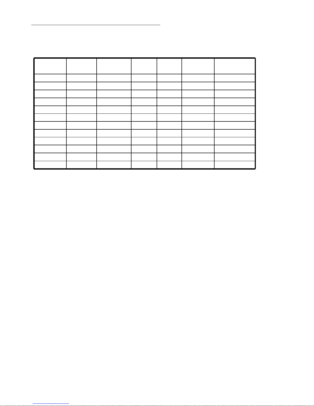
0,322014011606251025975.4G
0,43019516457001025975.6G
0,5530190116062514251375.5G
0,6445300164562514251375.8G
0,630320161070014451375.12G
0,645300164570014251375.6G
0,2910708006251025975.2G
0,352014011606251025975.5G
0,443019516456251025975.8G
0,491510080062514251375.2G
0,5230190116062514251375.4G
0,6451350164562517251675.8G
Electrical power
(kw)
Gas
power (kw)
weight
(kg)
Height
(mm)
depth
(mm)
Lenght
(mm)
Référence
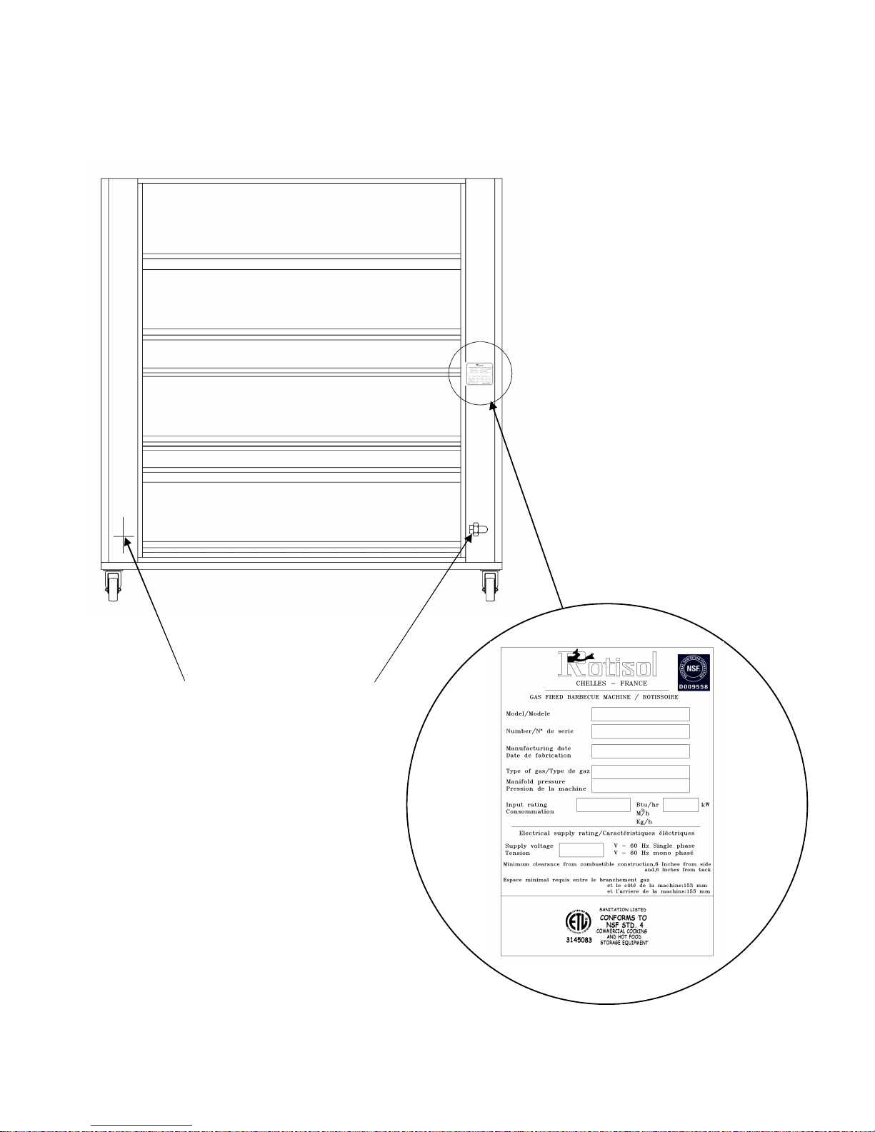
1.3. SITE OF MANUFACTURERS PLATE
It is situated on the rear, right hand side of the unit.
GAS INLET
ELECTRICAL
CONNECTION
Rear of the rotisserie
All this information are the property of Rotisol.
Reproduction partial or in totality are prohibited without authority prior written of company Rotisol.
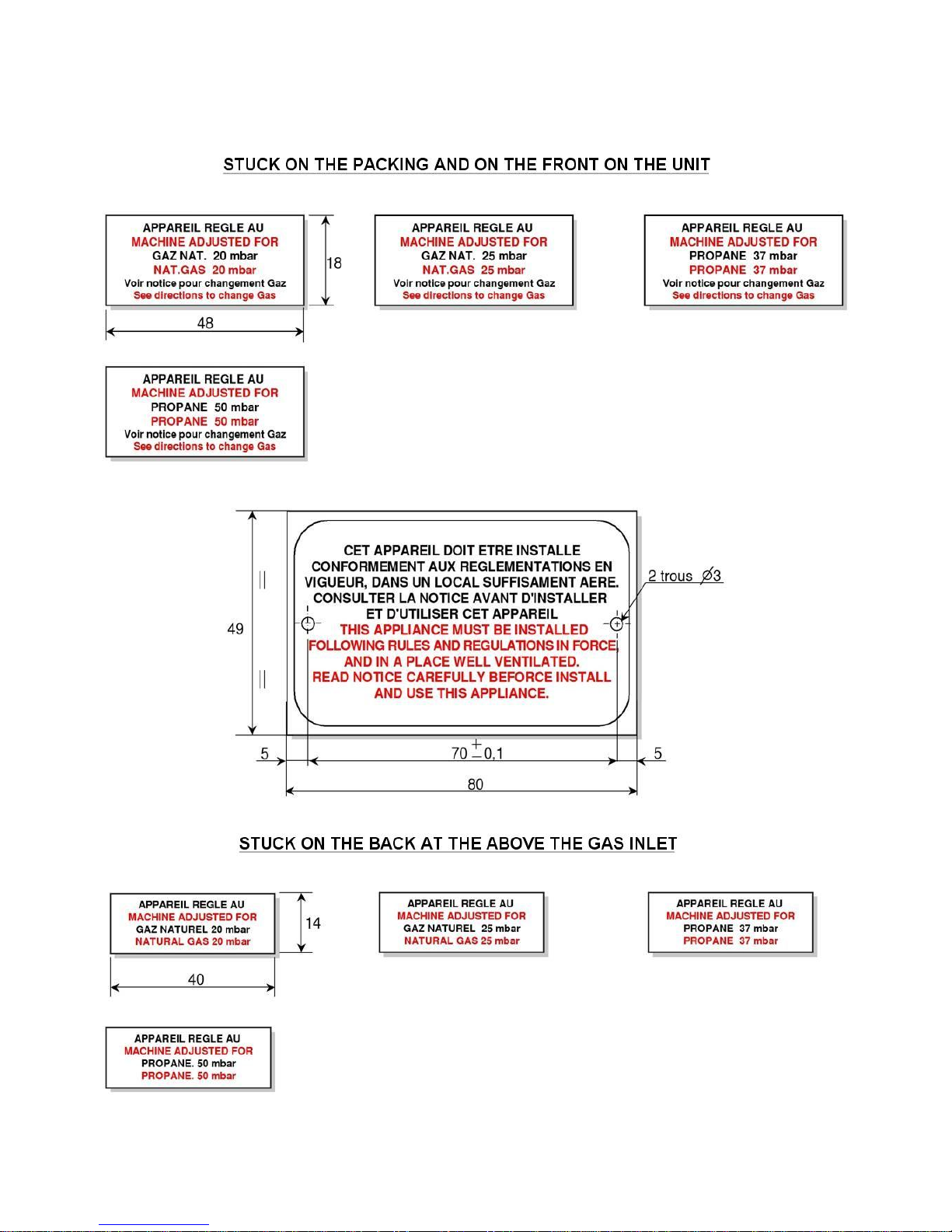
1.4. COMPULSORY MARKINGS
1.4.1. ON THE ROTISSERIE AND ON THE PACKING
All this information are the property of Rotisol.
Reproduction partial or in totality are prohibited without authority prior written of company Rotisol.
2. SETTING UP UNIT AND STARTING UP
• Before connecting and starting up the rotisserie. Ensure that the gas and electrical connections are
present.
This work are at the client cost, that he needs to have done by are a agreed company, near the
position that the rotisserie is to be les faire exécuter, par des sociétés.
The new air flow require for the combustion is : 2 m3/h par kW of the calorifique flow.
2.1. SETTING UP
2.1.1. UNPACKING
Unpack the rotisserie thatis circled, filmed and fixed on palette
.
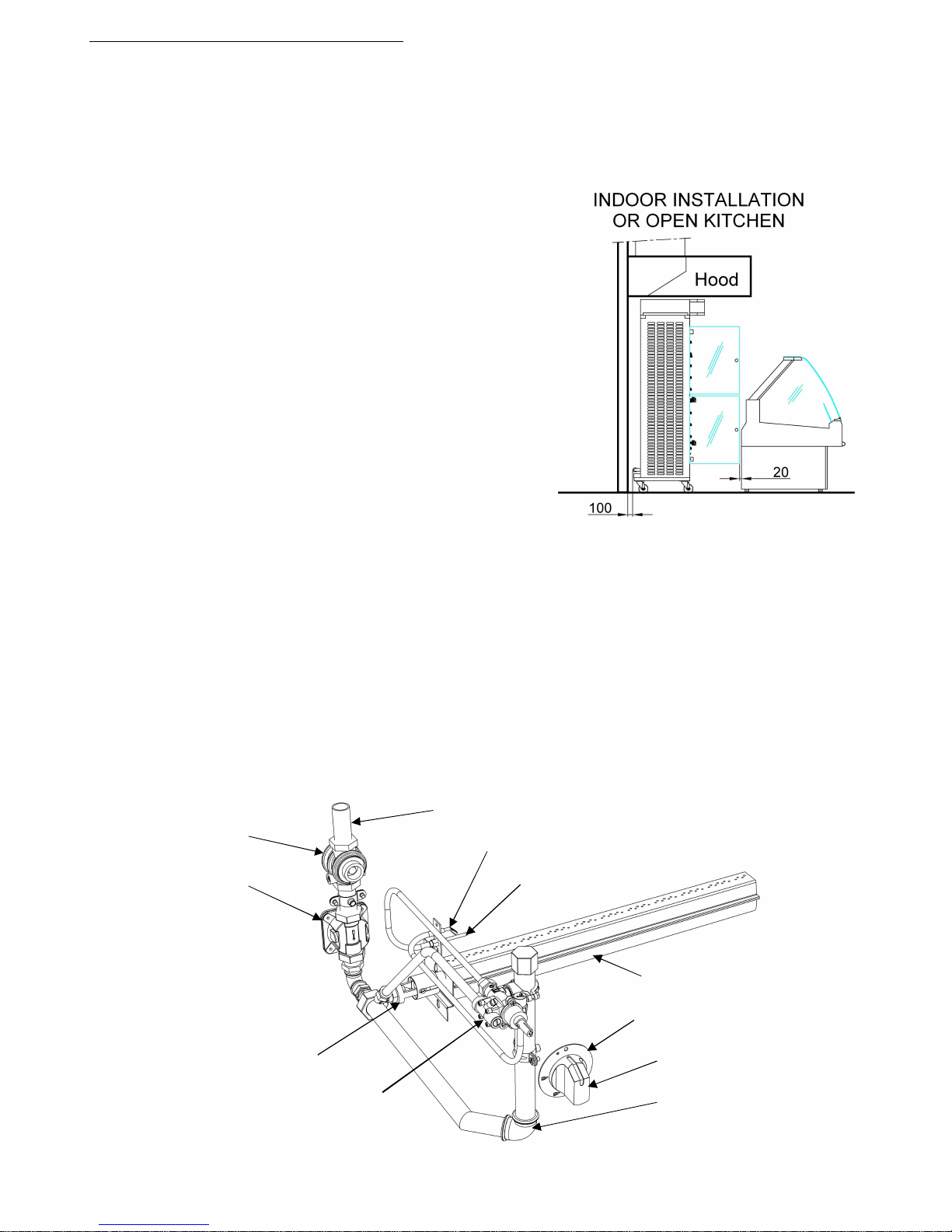
2.1.2. INSTALLING THE UNIT NEXT TO WALLS
AND APPLIANCES
The unit with glace door open should be placed at a distance
minimum of 20mm to adjacent walls.
2.1.3. APPLIANCE EQUIPPED WITH WHEELS
The device must be placed on a perfectly level ground and
locked in a stationary position for use and et le stockage
.
2.1.4. ENVIRONNEMENT
The device should not be installed near the steam,grease
(frying,…), projections of water, high températures or other
adverse condition.
2.2. GAS CONNECTION
The gas supply pipe will be sized to minimize losses power. It’s diameter will be determined
in function to it’s route (length, number of bends etc...) and the total power rating of the unit.
« Check that the settings of the unit corespond to the nature and preassure of the gas at the
premises.
In order to check the pressure of the unit, you just need to attached a manometer to the water gage at the
gas inlet on the rear of the unit, with all the burners on full.
The pressure measured should be the same as that indicated on the gas label, stuck to the unit.
The gas supply valves require no rotisserie set-up during their lifetime.
2.2.1. GAS CIRCUIT DIAGRAM
All this information are the property of Rotisol.
Reproduction partial or in totality are prohibited without authority prior written of company Rotisol.
Gas stopcock
Maxitrol regulator
Pilot
Thermocouple
Injector / Injector Support
Adjusting ring of the primary air
Gas cock
Knob ring
Gas knob
Gas line
Burner
Gas connection Ø 20/27
2.2.2. POSITION OF THE THERMOCOUPLE & PILOT LIGHT
2.2.3. POSITION OF THE INJECTOR AND THE SLEEVE FOR THE AJUSTMENT OF
THE PRIMARY AIR.
All this information are the property of Rotisol.
Reproduction partial or in totality are prohibited without authority prior written of company Rotisol.
FIXED
2.2.4. FIXED INSTALATION – MOBILE INSTALATION
All this information are the property of Rotisol.
Reproduction partial or in totality are prohibited without authority prior written of company Rotisol.
Connection type union 1 or 2
The use of TURBOGAS or similar in professional fixed instalations,willpermit a total liberty in the
conception of the kitchen.
MOBILE
The conception of a kitchen with mobile gas appliance is possible thanks to a tamdem of
TURBOGAZ - TUSHGAS or SIMILAR.
FLEXIBLE PIPPING IN THE SHAPE OF UU
Measure of the gas flow under 20 mbar in kW/h PCI(natural gaz)
2.3. ELECTRICAL CONNECTION
Check that there is no errors with CONNECTION.
• Electrical rating : 230V~50Hz.
• Check that the installed power corresponds with the characteristics on the signal plate
at the rear of the unit.
IN ALL CASES , CONNECT THE EARTH WIRE
THE UNIT IS DELIVERED IN MONOPHASE + EARTH
2.4. EVACUATION - SMOKE TYPE : A
• The unit is destined to be installed under an extraction system with ventilation
• A heat delector with holes is placed above the rotisserie
VIEW FROM ABOVE
All this information are the property of Rotisol.
Reproduction partial or in totality are prohibited without authority prior written of company Rotisol.
108513751375-12G
685975975-8G
685975975-6G
108513751375-6G
108513751375-8G
108513751375-5G
108513751375-4G
138516751675-8G
685975975-2G
685975975-4G
685975975-5G
108513751375-2G
Measurement
B (mm)
Measurement
A (mm)
Reference
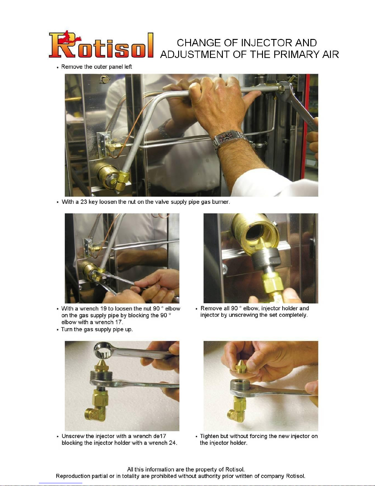
3. ADAPTING THE UNIT IN THE CASE OF CHANGING FROM ONE GAS TO ANOTHER
3.1. CHANGING THE INJECTOR
3.3. ADJUSTMENT OF THE PRIMARY AIR
You need to adjust the opening of the air sleeve to dim. D coresponding to the type of gas used ( see
position of the air sleeve, chapter 2.2.3 and the table of adjustment of the burner, chapter 3.7).
3.3.
TABLE FOR ADJUSTMENT OF ONE BURNER
TIGHTENING
RINGS
GAS SUPPLY PIPE
ELBOW OF 90°
ELBOW NUT OF 90°
INJECTOR HOLDER
INJECTOR
AIR INLET
SLEEVE
BURNER
SLEEVE FOR THE
ADJUSTMENT OF
PRIMARY AIR
ELBOW NUT OF 90°
All this information are the property of Rotisol.
Reproduction partial or in totality are prohibited without authority prior written of company Rotisol.
12,59,56,55Presure at the tap for the reduced flow in mbar
7,57,57,57,5Reduced heat flow in KW
1,161,16--Mass flow kg/h
--1,851,59Flow volumein m3/h
452,52,5
Opening of the primary air
« D » in mm (chapitre 2.2.3)
1,822,92,9Diamete rof injector in mm
180200290290injector making
15151515Heat flow in kW
GF 1375
12,59,555Presure at the tap for the reduced flow in mbar
8,58,58,58,5Reduced heat flow in KW
1,321,32--Mass flow kg/h
--2,091,8Flow volumein m3/h
4513,513,5
Opening of the primary air
« D » in mm (chapitre 2.2.3)
1,92,153,13,1Diamete rof injector in mm
190215310310injector making
17171717Heat flow in kW
GF 1675
12,59,56,55Presure at the tap for the reduced flow in mbar
5555Reduced heat flow in KW
0,7760,776--Mass flow kg/h
--1,231,06Flow volumein m3/h
452,52,5
Opening of the primary air
« D » in mm (chapitre 2.2.3)
1,51,652,42,4Diamete rof injector in mm
150165240240injector making
10101010Heat flow in kW
GF 975
G31 under 50 mbarG31 under 37 mbarG25 under 25 mbarG20 under 20 mbarCARACTERISTICSMODEL
 Loading...