

Page 1

Quality uncompromised
ROTEL
R
Technical
Manual
Table of Contents
Specification…………………...2
Wiring Diagram…………….….3
Disassembly Diagram..…...….4
Disassembly Diagram List..….5
Parts List……………………….6-14
Chassis Layout..…………...…15
Adjustment………………….…16-17
PCB Assembly…………….….18-20
Schematic Diagram……….….21-26
AM/FM STEREO RECEIVER
RX-975
THE ROTEL CO., LTD.
SHINSEN-BLD. 4F 10-10 SHINSEN-CHO, SHIBUYA-KU,
TOKYO 150-0045, JAPAN
Serial No.
Beginning
Y-319A-99092C/R-R
Page 2

Specification
Audio
Continuous Amplifier Power: 100 watts/channel
Total Harmonic Distortion: <0.05 % at rated power
Intermoduration Distortion (60 Hz : 7 kHz): <0.05 % at rated power
Frequency Response: Line Level: 10 - 70 kHz, ± 3dB
Signal to Noise Ratio (IHF”A” weighted): 92 dB
Input Overload: Line Inputs: 5 V
Preamplifier Output Voltage: 1.1 V
Input Sensitivity / I mpedance: Line Level: 200 mV / 47kohms
Tone Controls ( Bass / Treble): ± 8 dB at 100Hz /10 kHz
Video
Frequency Response: 3 Hz-10 MHz, ± 3dB
Signal to Noise Ratio: 92 dB
Input Impedance: 75kohms
Output Level: 1 volt
FM Tuner
(20-20 kHz, <0.05%, 8ohms)
Phono: 20 - 20 kHz, ± 1.5dB
Phono input: >120 mV
Phono: 3.1 mV / 47 kohms
Usable Sensitivity: 14.2 dBf
50 dB Quieting Sensitivity: 20.2 dBf (mono)
45.3dBf (stereo)
Signal to Noise Ratio (at 65 dBf): 70 dBf (mono)
65 dBf (stereo)
Harmonic Distortion (at 65 dBf): 0.3% (mono)
0.5% (stereo)
Frequency Response: 30 Hz- 14kHz, ± 1.5dB
Capture Ratio: 2.0 dB
Alternative Channel Selectivity 47 dB (± 400kHz)
Spurious Response Ratio: 80 dB
Image Response Ratio: 65 dB
IF Response Ratio: 80 dB
AM Suppression Ratio: 52 dB
Stereo Separation (100Hz/ 1 kHz/ 10 kHz): 40 dB/ 45 dB/ 35 dB
Output Level: 550 mV
Antenna Input: 75 ohms
unbalanced
AM Tuner
Sensitivity: 500 uV/m
Selectivity: 25 dB
Image Response Ratio: 35 dB
Signal to Noise Ratio: 40 dB
Output Level: 160 mV
Antenna Input: Loop Antenna
General
Power Consumption: 350 watts
Power Requirements (AC): 115Volts, 60 Hz (USA version)
230 Volts, 50 Hz (European version)
Weight: 11.5 Kg / 25.4 lb.
Dimensions (W x H x D): 450 x 158 x 400 mm
173/4” x 61/4” x 153/4”
2
Page 3

Wiring Diagram
3
Page 4
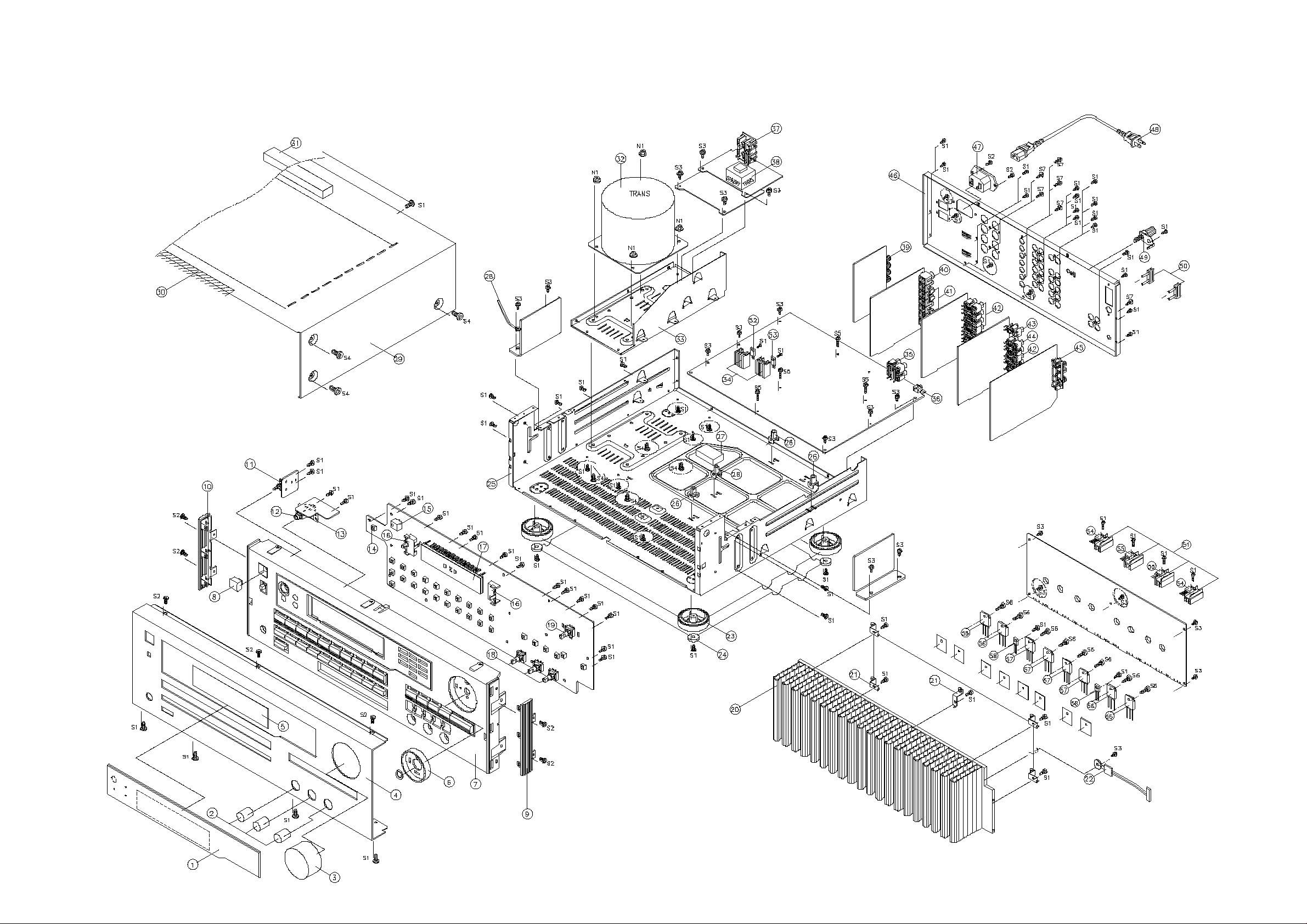
Disassembly Diagram
4
Page 5
Disassembly Diagram List
NO. PARTS NO. DESCRIPTION NO. PARTS NO. DESCRIPTION
1 8553000211 WINDOW DISPLAY. ACRYL 3.0t 52 2168602114 IC KIA7915P REG.
2 8545000211 KNOB ROTARY, AL A6063S-T5 53 2168602019 IC KIA7815P REG.
3 8543000211 KNOB MAIN, AL A6063S-T5
4
8602000311 FRONT PANEL, AL A6063S-T5
5 8535000110 FILTER, ACRYL 1.0t 56 2028416122
6 8545000311 BEZEL RING, ABS BLACK
7 8521000110 FRONT BODY, ABS BLACK 58 2008622110 TRANSISTOR 2SC4137 FOR BIAS
8 8545000110 POWER BUTTON, ABS BLACK
9 8523000120 SIDE CAP(RIGHT), ABS BLACK
10 8523000110 SIDE CAP(LEFT), ABS BLACK
11 4628000110 POWER SWITCH, TV-5
12 4438000210 PHONE JACK 9P(GOLD)
13 6505000210 PHONE BRAKET 0.6t
14 4658000110 TACT SWITCH
15 2408000180 REMOCON SENSOR CRV1M352-B
16 6515000110 HOLDER FIP, ABS BLACK
17 2328000304 FIP SVR-12MM18(35S/12G)
18 3218000210 VR ROTARY, ENCODER
19 3218000110 VR MAIN, ENCODER
20 7502000210 POWER HEAT SINK, AL A6063S-T5
21 6505000110 BRAKET HEAT SINK, SECC1.0t
22 436102101535 ASS'Y POSISTOR
23 6133100110 FOOT, ABS BLACK
24 6715000110 BUMPON
25 6121600110 MAIN CHASSIS, SECC1.2t
26 6515000210 SPACER PCB, ABS BLACK
27 6715000410 SPONGE, 80x20x9t
28 6528000210 CLAMP WIRE
29 6122000110 TOP COVER, VCM 0.95t
30 6715000210 SPONGE, 260X20X1t
31 6715000510 SPONGE, 90x40x12t
32
2828000067
33 6122600110 FRAME T/F, SECC 1.0t
34 7505000210 REG TR HEAT SINK(24X30), AL
35 4438101120 RCA JACK 4P(WR,WR)
36 4438300110 JACK RCA(MINI)
37
4448000110
38
2828000037
39 4408100910 SPEAKER TERMINAL 8P(RBRB,RBRB)
40 4438100720 RCA JACK 1P(Y), VIDEO
41 4438100520 RCA JACK 3P(Y), VIDEO
42 4438100320 RCA JACK 6P(WWW,RRR)
43 4438100120 RCA JACK 2P(W,R)
44 4438100220 RCA JACK 4P(WW,RR)
45 4408000310
46 6102000211
47 4448000310
48 4308000410
49 4408200110 TERMINAL G.N.D
50 4428000110 JUMPER PLUG
51 7505000110 REG TR HEAT SINK(15X30), AL
POWER TRANS(022 T-1068N01)
AC OUTLET
STANDBY TRANS(120V/60Hz)
ANT TERMINAL(SCREW)
BACK CHASSIS, SECC1.0t
AC INNET
INNET CORD AC POWER
54
55
57
2028316100
2028016100
2028116108
TRANSISTOR 2SC4833A-Y
TRANSISTOR 2SA1859A-Y
TRANSISTOR 2SC3519A W/ACC
TRANSISTOR 2SA1386A W/ACC
5
Page 6

Parts List
Q,Q,Q,Q,Q,Q
,,,,,
6
PART NO. DESCRIPTION SYMBOL NO.
AMP PCB 4002001200 ASSEMBLY
4002001200 Assembled PCB
2008207101 TRANSISTOR 2SA1360(O/Y) QL207,QR207
2008607106 TRANSISTOR 2SC3423(O/Y) QL209,QR209
2028016100 TRANSISTOR 2SA1859A-Y QL212,QR212
2028316100 TRANSISTOR 2SC4883A-Y QL211,QR211
2648601470 COIL INDUCTOR 0.5UH LL201,LR201
3049259573 RES WW 0.25 2W J RL235,RL245-247,RR235,RR245-247
3479347181 CAP E SG 470UF/63V CL208,CL209,CR208,CR209
436502102167 CTJ 0210 201,210 DL #18 P7.92 CN203
436502252166 CTJ 0225 201,210 DL #18 P3.96 CN202
436502302166 CTJ 0230 201,210 DL #18 P3.96 CN201
4428502526 CNT PLUG ST MO 5267-02 CP204,CP602
4428505526 CNT PLUG ST MO 5267-05 CP201
7505000110 H/SINK REG TR 15X30
2058322101 DIODE 1N4148 D206,DL201,DL202,DR201,DR202
2208206104 TRANSISTOR KTA1268(GR/BL)
2208206105 TRANSISTOR KTA1266Y Q218,QL203,QL204,QR203,QR204
2208606104 TRANSISTOR KTC3198Y-AT Q219,Q220,QL217,QR217
2208606108 TRANSISTOR KTC3200(GR/BL) QL206,QL208,QR206,QR208
2238006104 TRANSISTOR KRC107M Q221
2258128002 DIODE 1N4004 DL203,DL204,DR203,DR204
2258599919 DIODE ZENER T-72 UZ9V1 ZD201
3029100470 RES MF 10 1W J RL243,RR243
3029102970 RES MF 1K 1/8W J R249,RL201,RR201
3029103970 RES MF 10K 1/8W J RL210,RR210
3029104970 RES MF 100K1/8W J R246
3029122970 RES MF 1K2 1/8W J RL223,RR223
3029150970 RES MF 15 1/8W J RL203,RL204,RR203,RR204
3029151970 RES MF 150 1/8W J RL209,RR209
3029152970 RES MF 1K5 1/8W J R252,RL212,RR212
3029154970 RES MF 150K 1/8W J R253
3029222970 RES MF 2K2 1/8W J RL237-240,RR237-240
3029223970 RES MF 22K 1/8W J RL221,RL222,RR221,RR222
3029243970 RES MF 24K 1/8W J RL242,RR242
3029332970 RES MF 3K3 1/8W J R248
3029333970 RES MF 33K 1/8W J
3029339970 RES MF 3R3 1/8W J RL231-234,RR231-234
3029392970 RES MF 3K9 1/8W J RL225,RR225
3029470470 RES MF 47 1W J RL227,RL228,RR227,RR228
3029471970 RES MF 470 1/8W J RL224,RR224
3029472970 RES MF 4K7 1/8W J RL217,RR217
3029561970 RES MF 560 1/8W J
3029680970 RES MF 68 1/8W J RL208,RR208
3029681970 RES MF 680 1/8W J RL205,RL241,RR205,RR241
5
9
RL213-216,RL218-219,RR213-216,RR218219
Page 7

Parts List
,,,,,
7
PART NO. DESCRIPTION SYMBOL NO.
3029682970 RES MF 6K8 1/8W J R250,RL244,RR244
3029683970 RES MF 68K 1/8W J R247
3029751970 RES MF 750 1/8W J RL206,RL207,RR206,RR207
3029820970 RES MF 82 1/8W J
3479310071 CAP E SG 10uF/50V CL210,CL216,CR210,CR216
3479310971 CAP E SG 1uF/50V C218
3479310991 CAP E SG 1UF/100V CR212,CR213
3479322031 CAP E SG 22UF/16V CL205,CR205
3479333061 CAP E SG 33UF/35V CL204,CR204
3479347111 CAP E SG 470UF/6.3V C219,CL207,CR207
3479347971 CAP E SG 4.7uF/50V CL201,CR201,CL211,CR211
3519033935 CAP C AXIAL 3.3PF/50V J CL206,CR206
3519680935 CAP C AXIAL 68PF/50V J CL202,CR202
3519681935 CAP C AXIAL 680PF/50V J CL203,CR203
3679104250 CAP MYLAR 0.1UF/250V J CL214,CR214
FRONT PCB 4002001000 ASSEMBLY
4002001000 Assembled PCB
2138322102 IC CPU CXP82832-180Q RX975 U601
2328000304 FIP SVR-12MM18(35S/12G) FL601
2408000180 REMOCON SENSOR CRV1M352-B RMC1
3218000110 VR ENCODER EC16B243040F
3218000210 VR ENCODER EC16B242040A
3439210415 CAP BACK-UP 0.1F/5.5V C614
3938124010 RESONATOR CST10.0MTW-TF01 XT601
436102233535 CTM 0223 5263,5394 DL #26 P2.5 CN602
436210433524 CTG 1043 S04,T04 DL #26 P2.0 CN856
4428617265 CNT FPC PLUG EL AN 00-8370-177 CP601
2058322101 DIODE 1N4148 D601-610,618-620
2208606104 TRANSISTOR KTC3198Y-AT Q601-603
2238006104 TRANSISTOR KRC107M Q604,605
2371140711 LED SLR56VR3FL D614-616
3029101970 RES MF 100 1/8W J R628
3029102970 RES MF 1K 1/8W J R601-610,644-647
3029103970 RES MF 10K 1/8W J R617,623,624,626,634-641
3029104970 RES MF 100K1/8W J R622
3029331970 RES MF 330 1/8W J R612,614,616,625
3029333970 RES MF 33K 1/8W J R618
3029472970 RES MF 4K7 1/8W J R611,613,615,619,627,629,642,643
3029473970 RES MF 47K 1/8W J R630-633
3029479970 RES MF 4R7 1/8W J R620-621
3479322871 CAP E SG 0.22UF/50V C616
3479333971 CAP E SG 3.3UF/50V C615
3479347971 CAP E SG 4.7uF/50V C612
3519101935 CAP C AXIAL 100PF/50V J C601-609,623,624
0
Page 8

Parts List
8
PART NO. DESCRIPTION SYMBOL NO.
3519103915 CAP C AXIAL 0.01UF/16V J C611,613
3519473935 CAP C AXIAL 0.047UF/50V J C617,618
3519821935 CAP C AXIAL 820PF/50V J C619-622,625,626
4658000110 SW TACT SKHVBED010 S601-604,609-610,612-633
HEAD PHONE PCB 4002001050 ASSEMBLY
4002001050 Assembled PCB
3029471570 RES MF 470 2W J R854-855
436204503524 CTG 0450 S04,T04 DL #26 P2.0 CN855
4438000210 JACK PHONE 9P G
3029223970 RES MF 22K 1/8W J R852-853
3519561935 CAP C AXIAL 560PF/50V J C852-853
POWER PCB 4002001020 ASSEMBLY
4002001020 Assembled PCB
2168602105 IC KIA7805P REG. U801
3419510241 CAP E SG 1000UF/25V C807
436203153524 CTG 0315 S03,T03 DL #26 P2.0 CN802
436204103524 CTG 0410 S04,T04 DL #26 P2.0 CN803
4428504576 CNT PLUG ST JST B04B-EH-A CP801
4428510416 CNT PLUG ST GIL-S-10P-S2T2-EF CP603
2058322101 DIODE 1N4148 D803,808,810
2208206105 TRANSISTOR KTA1266Y Q801
2208606104 TRANSISTOR KTC3198Y-AT Q802-804
2258128002 DIODE 1N4004 D804-807
2258599300 DIODE ZENER T-72 UZ30V D802
2258599439 DIODE ZENER T-72 UZ4V3 D809
2258599919 DIODE ZENER T-72 UZ9V1 D801
3029102970 RES MF 1K 1/8W J R801
3029103970 RES MF 10K 1/8W J R802
3029332970 RES MF 3K3 1/8W J R804-806
3029470470 RES MF 47 1W J R808
3029470970 RES MF 47 1/8W J R809
3029472970 RES MF 4K7 1/8W J R810-811
3029560970 RES MF 56 1/8W J R803
3479310071 CAP E SG 10uF/50V C801
3479310971 CAP E SG 1uF/50V C808-809
3479347071 CAP E SG 47UF/50V C802
3519104935 CAP C AXIAL 0.1UF/50V J C810,C803
3519473935 CAP C AXIAL 0.047UF/50V J C804-806,811
POWER SWITCH PCB 4002001060 ASSEMBLY
4002001060 Assembled PCB
3549472109 CAP C 0.0047UF/400V AC C854
436502402167 CTJ 0240 201,210 DL #18 P7.92 CN852
Page 9

Parts List
2
9
9
PART NO. DESCRIPTION SYMBOL NO.
4628000110 SW PWR SDDLB15700
SPEAKER PCB 4002001040 ASSEMBLY
4002001040 Assembled PCB
3029100570 RES MF 10 2W J R451-452
4408100910 TERMINAL SPK 8P(RBRB,RBRB)
4428502646 CNT PLUG ST JE202A-1 T-2 P3.96 CT452,453
4428503416 CNT PLUG ST GIL-S-3P-S2T2-EF CP802
4428503646 CNT PLUG ST JE202A-1 T-3 P3.96 CT451
4428504416 CNT PLUG ST GIL-S-4P-S2T2-EF CP855
5528053001 RELAY DH24D2-OT(M) RLY451,452
2258128002 DIODE 1N4004 D451-452
3679472120 CAP MYLAR 0.0047UF100V J C453-456
3679473120 CAP MYLAR 0.047UF/100V J C451-452
STANDBY PCB 4002001010 ASSEMBLY
4002001010 Assembled PCB
2648701170 FILTER TR25 T852
2828000037 T/F STANDBY RSX965(120V/60Hz) T851
3549472109 CAP C 0.0047UF/400V AC C851
4428502726 CNT PLUG ST MO 35328-0210 P7.92 CP853
4428502746 CNT PLUG ST JE202B-1 T-2(3-2) P7.9
4428503746 CNT PLUG ST JE202B-1 T-3(5-2,4) P7.
4428504416 CNT PLUG ST GIL-S-4P-S2T2-EF CP803
4448000110 AC OUTLET(A),CCT1304-0212
5508101431 FUSE 51S 315MA/250V F851
5508102031 FUSE 51S 1A/250V F853
5508103031 FUSE 51S 5A/250V F852
5528001640 RELAY G5PA-1 DC12V RLY851
2258128002 DIODE 1N4004 D851
3029335380 RES MF 3M3 1/2W J ERC R851
CP852
CP851
VIDEO PCB 4002001030 ASSEMBLY
4002001030 Assembled PCB
2108499133 IC MC14577 U402
2168017141 IC LC7824 ANALOG SWICH U401
4428807464 CNT HOUSING EL 20-8283-007 CB401
4438100520 JACK RCA 3P(Y)
4438100720 JACK RCA 1P(Y)
2238422100 TRANSISTOR DTC323TSTP Q401
3029102970 RES MF 1K 1/8W J R410-412
3029470970 RES MF 47 1/8W J R417-423
3029471970 RES MF 470 1/8W J R413-413,424
3029750970 RES MF 75 1/8W J R401-407
3479310071 CAP E SG 10uF/50V C417-423,C414-415
Page 10

Parts List
10
PART NO. DESCRIPTION SYMBOL NO.
3479347031 CAP E SG 47UF/16V C404,409,411,413
3479347121 CAP E SG 470UF/10V C401,416
3519101935 CAP C AXIAL 100PF/50V J C405-407
3519103915 CAP C AXIAL 0.01UF/16V J C403,C408,410,412
INPUT AUDIO PCB 4002000400 ASSEMBLY
4002000400 Assembled PCB
2168017132 IC LC78211 ANALOG SWITCH U302
2168220135 IC NJM5532D DUAL OPAMP U301,303
4428807464 CNT HOUSING EL 20-8283-007 CP302
4428808464 CNT HOUSING EL 20-8283-008 CP301
4438100120 JACK RCA 2P(W,R) RCA301
4438100220 JACK RCA 4P(WW,RR) RCA302
4438100320 JACK RCA 6P(WWW,RRR) RCA303
2058322101 DIODE 1N4148 D301
3029101970 RES MF 100 1/8W J RL/R311-315,326,330
3029102970 RES MF 1K 1/8W J R319-321,RL/R301
3029103970 RES MF 10K 1/8W J RL/R328
3029104970 RES MF 100K1/8W J R318,RL/R308,327,329
3029221970 RES MF 220 1/8W J R309,310,316,317,322,323
3029433970 RES MF 43K 1/8W J RL/R305
3029561970 RES MF 560 1/8W J RL/R307
3029564970 RES MF 560K 1/8W J RL/R304
3029821970 RES MF 820 1/8W J RL/R306
3029913970 RES MF 91K 1/8W J RL/R302,303
3479310971 CAP E SG 1uF/50V C323
3479322871 CAP E SG 0.22UF/50V CL/R307
3479333061 CAP E SG 33UF/35V CL/R309
3479347041 CAP E SG 47uF/25V C309,310,324,326-328
3479347971 CAP E SG 4.7uF/50V CL/R303,330,333
3519101935 CAP C AXIAL 100PF/50V J C325,CL/R301,302,313-322,331-332
3679182120 CAP MYLAR 0.0018UF/100V J CL/CR305,CL/CR308
3679222120 CAP MYLAR 0.0022UF/100V J CL/R304
3679562120 CAP MYLAR 0.0056UF/100V J CL/R306
INPUT VIDEO PCB 4002000410 ASSEMBLY
4002000410 Assembled PCB
2138001115 IC MULTIFLEX BU4053BC U352
2168017132 IC LC78211 ANALOG SWITCH U351
4428809464 CNT HOUSING EL 20-8283-009 CP351
4438100320 JACK RCA 6P(WWW,RRR) RCA351-2
2058322101 DIODE 1N4148 D351
3029101970 RES MF 100 1/8W J RL/R350-355
3029102970 RES MF 1K 1/8W J R362-364
3029104970 RES MF 100K1/8W J R360,RL/R366
Page 11

Parts List
2
9
11
PART NO. DESCRIPTION SYMBOL NO.
3029221970 RES MF 220 1/8W J R361,365,
3029332970 RES MF 3K3 1/8W J R356-359
3479310971 CAP E SG 1uF/50V C366
3479347041 CAP E SG 47uF/25V C363-365,367
3479347971 CAP E SG 4.7uF/50V CL/R362
3519101935 CAP C AXIAL 100PF/50V J C368,CL/R350-361
MAIN PCB 4002001100 ASSEMBLY
4002001100 Assembled PCB
2058100139 DOIDE BRIDGE KBPC2504W-F DB101
2138007120 IC TC9459F ELECT VOL U108
2138007130 IC TC9184P ELECT TONE U105
2168220135 IC NJM5532D DUAL OPAMP U107
2168602109 IC KIA7815P REG. U102
2168602114 IC KIA7915P REG. U103
2408000136 OPTO. COUPLER LTV-817 U101
3409333261 CAP E SG 3300UF/35V C103,C104
3419512381 CAP E AM 12000UF/80V C101,C102
436105409035 CTM 0540 5263,5394 DS #26 P2.5 W201
436503252166 CTJ 0325 201,210 DL #18 P3.96 CN451
4428502746 CNT PLUG ST JE202B-1 T-2(3-2) P7.9
4428503576 CNT PLUG ST JST B03B-EH-A CP204
4428503746 CNT PLUG ST JE202B-1 T-3(5-2,4) P7.
4428617266 CNT FPC PLUG EL ST 00-8370-171 W601
4428807466 CNT PLUG EL 00-8283-0712 W401,W302
4428808466 CNT PLUG EL 00-8283-0812 W301
4428809466 CNT PLUG EL 00-8283-0912 W351
4428810466 CNT PLUG EL 00-8283-1012 W701
4438101120 JACK RCA 4P(WR,WR)
4438300110 JACK RCA YKB21-5103A
5508102031 FUSE 51S 1A/250V F101,F102
7505000210 H/SINK REG TR(24X30)
2208206105 TRANSISTOR KTA1266Y Q106
2208606104 TRANSISTOR KTC3198Y-AT Q104,Q105
2238006103 TRANSISTOR KRA107M Q103
2238422100 TRANSISTOR DTC323TSTP Q101,Q102
2258128002 DIODE 1N4004 D101-D104
2258599270 DIODE ZENER T-72 UZ27V ZD103
2258599569 DIODE ZENER T-72 UZ5V6 ZD104,ZD105
3029101970 RES MF 100 1/8W J R107,R108,R129,R130
3029102970 RES MF 1K 1/8W J R104,R109-R110,R113-R118,R151,R152
3029104970 RES MF 100K1/8W J R133,R134
3029122970 RES MF 1K2 1/8W J R149,R150
3029221970 RES MF 220 1/8W J R106,R111,R112,R119,R120
3029273970 RES MF 27K 1/8W J R145,R146
CP203
CP102
Page 12

Parts List
12
PART NO. DESCRIPTION SYMBOL NO.
3029393970 RES MF 39K 1/8W J R139,R140
3029471970 RES MF 470 1/8W J R131,R132
3029472970 RES MF 4K7 1/8W J R103,R105,R143,R144
3029474970 RES MF 470K 1/8W J R135,R136
3029562970 RES MF 5K6 1/8W J R147,R148
3029564970 RES MF 560K 1/8W J R141,R142
3029823970 RES MF 82K 1/8W J R137,R138
C119,C120,C129,C130,C131,C143,C144,
3479310071 CAP E SG 10uF/50V
3479310971 CAP E SG 1uF/50V C117,C118,C149,C150
3479347041 CAP E SG 47uF/25V C135,C136,C163,C164
3479347971 CAP E SG 4.7uF/50V C123,C124,C155,C156
3519101935 CAP C AXIAL 100PF/50V J C132,C145,C146
3519270935 CAP C AXIAL 27PF/50V J C147,C148
3579104530 CAP C RADIAL 0.1UF/50V J C115,C116,C125,C126,C137,C138
3679104250 CAP MYLAR 0.1UF/250V J C105-C109
3679123120 CAP MYLAR 0.012UF/100V J C153,C154
3679223120 CAP MYLAR 0.022UF/100V J C159,C160
3679272120 CAP MYLAR 0.0027UF/100V J C157,C158
3679473120 CAP MYLAR 0.047UF/100V J C110-C114
3679683120 CAP MYLAR 0.068UF/100V J C151,C152
C161,C162
TUNER PCB 4002001300 ASSEMBLY
4002001300 Assembled PCB
2138017136 IC LM7001 PLL IC701
2168017128 IC LA1266 IF IC702
2168417120 IC LA3401 MPX U703
2258817101 DIODE VARACTOR SVC321SPA-C VD701,702
2618231001 COIL AM-ANT1 M7ZN-K5643A-KR T701
2638231001 COIL AM IFT A7MC-K672713N4-KR T703
2638231001 COIL AM IFT A7MC-K672713N4-KR T702
2658031001 COIL MPX LPF 253AGG-K5001-KR TL706,TR706
2838501111 COIL FM-DET-A1 292BCA-K5713FKG T704
2838501112 COIL FM-DET-B1 292BCA-K5714X T705
3615471110 CAP POLY 470PF/50V J C715
3838001000 TRIMMER 10PF TZ03-T110FR(WHT) TC701
3908001020 FILTER BFU450C4N CF704
3908011071 FILTER FM IF SFE10.7MA5 CF701,702,703
3908101030 CLYSTAL 7.2MHZ X701
3928001010 FRONT-END FTA4-575H FE1
3938131600 RESONATOR CSB-456F15 X702
4408000310 TERMINAL ANT,SC021058KN
4428810464 CNT HOUSING EL 20-8283-010 CB701
2058322101 DIODE 1N4148 D702
2208406103 TRANSISTOR KTC3194Y(KTC1923Y) Q703
Page 13

Parts List
13
PART NO. DESCRIPTION SYMBOL NO.
2208606104 TRANSISTOR KTC3198Y-AT Q701,702
2238006103 TRANSISTOR KRA107M Q704,705,706,709
2238422100 TRANSISTOR DTC323TSTP QL708,QR708
2258599519 DIODE ZENER T-72 UZ5V1 ZD701
3029101970 RES MF 100 1/8W J R716,734,739
3029102970 RES MF 1K 1/8W J R710,717-719,
3029103970 RES MF 10K 1/8W J R707,727,731
3029104970 RES MF 100K1/8W J R701,704,706
3029124970 RES MF 120K 1/8W J RL746,RR746
3029152970 RES MF 1K5 1/8W J RL757,RR757
3029181970 RES MF 180 1/8W J R711
3029184970 RES MF 180K 1/8W RL747,RR747
3029220970 RES MF 22 1/8W J R729
3029223970 RES MF 22K 1/8W J R726,728,741,743
3029271970 RES MF 270 1/8W J R708,721
3029272970 RES MF 2K7 1/8W J RL748,RR748
3029331970 RES MF 330 1/8W J R720
3029332970 RES MF 3K3 1/8W J R713,733,742,RL749,RR749
3029471970 RES MF 470 1/8W J R705,715,722
3029472970 RES MF 4K7 1/8W J R724,730
3029473970 RES MF 47K 1/8W J R740,744
3029561970 RES MF 560 1/8W J R709,712,714
3029562970 RES MF 5K6 1/8W J R702,732
3029623970 RES MF 62K 1/8W J R703
3029683970 RES MF 68K 1/8W J R725
3248022443 VR SEMI 220K(B)-H RH063MCJ5R VR703
3248047243 VR SEMI 4K7(B)-H RH063MCS3R VR701
3248047343 VR SEMI 47K(B)-H RH063MCS4R VR702
3479310071 CAP E SG 10uF/50V C720,739,749,753,CL751,CR751
3479310131 CAP E SG 100UF/16V C714,735,744
3479310971 CAP E SG 1uF/50V C733,745,747
3479322871 CAP E SG 0.22UF/50V C746
3479333971 CAP E SG 3.3UF/50V C703,727
3479347031 CAP E SG 47UF/16V C711,705
3479347971 CAP E SG 4.7uF/50V C726,728,741
3519101935 CAP C AXIAL 100PF/50V J C710
3519103915 CAP C AXIAL 0.01UF/16V J C704,707,723
3519150935 CAP C AXIAL 15PF/50V J C716
C701,706,712,713,717,718,721,722,724,7
3519223520 CAP C AXIAL 0.022UF/25V J
3519331935 CAP C AXIAL 330PF/50V J C736
3519473935 CAP C AXIAL 0.047UF/50V J C742,C702
3519561935 CAP C AXIAL 560PF/50V J CL750,CR750
3519680935 CAP C AXIAL 68PF/50V J CL752,CR752
3519681935 CAP C AXIAL 680PF/50V J C743
25,729,734,C748
Page 14

Parts List
14
PART NO. DESCRIPTION SYMBOL NO.
3528180210 CAP C RADIAL 18PF/50V(CH) J C708,709
3679223120 CAP MYLAR 0.022UF/100V J C730
3679332120 CAP MYLAR 0.0033UF/100V J C731
3679393120 CAP MYLAR 0.039UF/100V J C732
HEAT SINK ASSEMBLY
2008622110 TRANSISTOR 2SC4137 FOR BIAS QL210,QR210
2028116108 TRANSISTOR 2SA1386A W/ACC QL215,QL216,QR215,QR216
2028416122 TRANSISTOR 2SC3519A W/ACC QL213,QL214,QR213,QR214
436102101535 POSISTOR P2.5 PTH9M04 MO 100mm
7502000210 POWER HEAT SINK
OTHERS
2608207360 AM ANTENNA LOOP
4348000110 FM ANTENNA
4428400110 MATCHING TRANS(A)
9007000410 INSTRUCTION MANUAL
9605000113 BOX CARTON(INNER)
9625000113 BOX CARTON(OUT)
9722000110 CUSHION POLY
6122000110 TOP COVER ,VCM 0.95T
6715000110 BUMPON
8535000110 FILTER FL, ACRYL 1.0T
8543000211 KNOB MAIN(AL)
8545000211 KNOB ROTARY(AL)
8545000311 BEZEL RING, ABS BLACK
8553000211 WINDOW DISPLAY
8602000311 PANEL FRONT(AL),RX975US
435602120067 CTW 0212 35156,INLET DL#18 P7.92
4408200110 TERMINAL GND
4428000110 JUMPER PLUG
6133100110 FOOT, ABS BLACK
6515000210 SPACER PCB, ABS BLACK
436617281182 CTW 1728 KFC,KFC NL 0.1mm P1.25
8521000110 BODY FRONT, ABS BLACK
8545000110 BUTTON PWR, ABS BLACK
Page 15

Chassis Layout
15
Page 16

Adjustment
16
1. FM Alignments
Necessary measurement equipment:
Stereo Generator, FM/AM Signal Generator, Distortion meter, Oscilloscope,
Digital Volt Meter (DVM)
(A) Center Adjust
Stereo Generator Setting: MODE; MONO, Audio Frequency; 1 kHz
FM Signal Generator Setting: Deviation; 75 kHz, Frequency; 98.1 MHz, Output Level; 66 dB
RX-975 Setting: FM Frequency; 98.1 MHz, FM MODE; MONO
1) Turn FM Signal Generator Modulation On.
2) Connect DVM (+) (-) terminals to both ends of resistor R726 and measure the volt.
3) Make this measured volt ‘0’ by adjusting T704 (FM-DET-A Coil). (The adjustment should be within ± 2mV)
4) After this adjustment, measure THD (Distortion) with Distortion Meter.
5) Adjust THD to minimum point with T-705 (FM-DET-B Coil). (THD should be within 0.5%)
(B) Channel Separation Adjust
Stereo Generator Setting: MODE; STEREO (Only L-channel or R-channel Signal Out),
Audio Frequency; 1 kHz
FM Signal Generator Setting: Deviation; 75 kHz, Frequency; 98.1 MHz, Output Level; 66 dB
RX-975 Setting: FM Frequency; 98.1 MHz, FM MODE; STEREO
1) Turn FM Signal Generator Modulation On after modulating only L-channel or R-channel at Stereo
Generator.
2) Confirm if ‘STEREO’ indicator is light On on the display.
3) Measure output level via Distortion Meter and make the level as standard.
4) Turn FM Signal Generator Modulation On after modulation only R-channel or L-channel at Stereo
Generator.
5) Measure output level via Distortion Meter (measure per a “dB”).
6) Adjust output level to minimum position with VR702. (lower than –40 dB)
(C) “Tune” Level Adjust
Stereo Generator Setting: MODE; STEREO, Audio Frequency; 1 kHz
FM Signal Generator Setting: Deviation; 75 kHz, Frequency; 98.1 MHz, Output Level; 26 dB
RX-975 Setting: FM Frequency; 98.1 MHz, FM MODE; STEREO
1) Turn FM Signal Generator Modulation On. (confirm if output level is 26 dB)
2) Adjust VR702 up ton the moment where ‘STEREO’ & ‘TUNE’ indicator turn OFF & ON again.
3) Confirm if ‘STEREO’ & ‘TUNE’ turn OFF when decreasing the output level slowly from 26 dB to 25 dB,
24dB ~ ~ ~. (Repeat the above 2)~3) if not OFF in lower than 24 dB)
4) Push RX-975’s TUNE UP and DOWN button “long” at Signal Generator Output Level 26 dB and start Auto
Search. Confirm if search stops at FM Frequency 98.1 MHz. (confirm both of High Frequency to 98.1 MHz
search, Low Frequency to 98.1 MHz search)
2. AM
Page 17

Necessary measurement equipment:
17
AM Signal Generator, Distortion Meter, Oscilloscope, Digital Volt Meter (DVM)
(A) VT Adjust
AM Signal Generator Setting:
1) Adjust AM Frequency of RX-975 to 520 kHz.
2) Connect (-) terminal of DVM with GND (or chassis) and connect (+) terminal with jumper J704 (VT
CHECK) and measure voltage. (Low Frequency VT)
3) Adjust VT to 1.2 volts with T-702 (AM-OSC Coil).
*In case of European version, AM frequency range is 522 kHz ~ 1611 kHz. So, adjust VT to 1.0 volt at 522
kHz. (Low Frequency VT)
(B) Output Level Adjust
AM Signal Generator Setting: Modulation; 30 %, Frequency; 400 Hz, Output Level; 84 dB
RX-975 Setting: AM Frequency; 600 kHz
1) Turn AM Signal Generator Modulation On.
2) Adjust output level to maximum point with T701 (AM-ANT Coil).
3) Adjust AM Signal Generator & RX-975 AM Frequency to 144 kHz and measure output level.
4) Adjust output level to maximum point with TC701 (WHITE trimmer).
5) Repeat above 2)~4) steps 2~3 times until adjusting to maximum output levels.
6) Adjust AM Signal Generator & RX-975 AM Frequency to 1000 kHz and measure output level.
7) Adjust level to maximum position with T703 (AM-IFT).
*In case of European version, AM Frequency Step is 9 kHz. So, change the standard frequency as below:
522 kHz as 520 kHz
1404 kHz as 1400 kHz
999 kHz as 1000 kHz
(C) TUNED Level Adjust
AM Signal Generator Setting: Modulation; 30 %, Audio Frequency; 400 Hz,
Radio Frequency; 1000 kHz Output Level; 84 dB
RX-975 Setting: AM Frequency; 1000 kHz
1) Turn AM Signal Generator Modulation On. (Make sure if Output level is 84 dB)
2) Adjust VR701 (AM-ADJ) up to the moment where ‘TUNED’ indicator turns OFF & ON again.
3) Confirm if ‘TUNED’ turns OFF when decreasing the output level of AM Signal Generator slowly from 84 dB
to 80 dB.
4) Push RX-975’s TUNE UP or DOWN button “long” at AM Signal Generator Output Level 84 dB and start
Auto Search.
Confirm if search stops at AM Frequency 1000 kHz. (Check with both of High Frequency to 1000 kHz
search, Low Frequency to 1000 kHz search)
*In case of European version, AM Frequency Step is 9 kHz. So, check above steps with 999 kHz instead
of 1000 kHz.
Page 18

NOTE
18
Page 19

AMP PCB 4002001200
PCB Assembly (1/3)
19
Page 20

PCB Assembly (2/3)
20
4002001060
4002001060
FRONT 4002001000
Page 21

PCB Assembly (3/3)
21
Page 22

Schematic Diagram(1/6)
22
AMP PCB 4002001200
Page 23

Schematic Diagram(2/6)
23
Front PCB 4002001000
Page 24

Schematic Diagram(3/6)
24
4002001040
4002001030
4002001020
4002001060
4002001010
4002001050
Page 25

Schematic Diagram(4/6)
25
INPUT AUDIO PCB
400200400
INPUT VIDEO PCB
400200410
Page 26

Schematic Diagram(5/6)
26
Main PCB 4002001100
Page 27

Schematic Diagram(6/6)
27
4002001300Tuner PCB
 Loading...