

Installation instructions and
Operator‘s Manual
for ROTAX®-engines type
125 MAX DD2 evo
Part no.: 297733 Edition: 10/2019
BRP-Rotax GmbH & Co KG | Rotaxstrasse 1 | 4623 Gunskirchen, Austria | T: +43 7246 601 0 | F: +43 7246 6370
www.rotax.com | www.rotax-kart.com

Genera
BRP-Rotax recommends products of the following companies:
l information

For inf
center or consult the workshop manual (available on the internet at www.rotax-kart.com).
We ask to hand over this manual, the engine identity card and the product and service
registration document to the new owner in case of a change of ownership.
ormation regarding the repair of the engine 125 MAX DD2 evo contact an authorized service
Preface
This document and all technical data and procedures therein are property of BRP-Rotax GmbH &
Co KG and based on the state of knowledge at the time of publication. The manual has been
drawn up to the best of our knowledge. However, we exclude any liability.
We reserve all rights including technical modification and possibility of errors.
Reprinting, translation or copies in whole or in part, are authorized only after written permission by
BRP-Rotax GmbH & Co KG.
BRP-Rotax GmbH & Co KG reserves the right at any time to discontinue or change specifications,
prices, designs, features, models or equipment without incurring any obligations.
Engine performance may vary depending on, among other things, general conditions, ambient
temperature and altitude.

BRP-Rotax
INSTALLATION MANUAL
Table of Content
Chapter INTRO –
Chapter 1 – Engine installation
Chapter 2 – Fuel system
Chapter 3 – Electric system
Chapter 4 – Cooling system
Chapter 5 – Exhaust system
Chapter 6 – Installation of the accessories
Chapter 7 – Finishing work
Effectivity: 125 MAX DD2 evo
Content
Page 1
Edition: September 01 2019

BRP-Rotax
INSTALLATION MANUAL
NOTES
Notes
Page 2
Edition: September 01 2019
Effectivity: 125 MAX DD2 evo
Edition /Rev. 0

Preface
Contents
General
BRP-Rotax
INSTALLATION MANUAL
Chapter: INTRO
For information regarding repair of the engine 125 MAX DD2 evo contact an authorized
service center or consult the workshop manual
(available on internet under www.rotax-kart.com).
We ask to hand over this manual, the engine identity card and the product and
service registration document to the new owner in case of a change of ownership.
This Installation Manual contains instructions for all the installation work on the ROTAX®Engine Type 125 MAX DD2 evo.
This document and all technical data and procedures therein are property of
BRP-Rotax GmbH & Co KG and based on the state of knowledge at the time of
publication The Manual has been drawn up to the best of our knowledge. However,
excluding any liability.
We reserve all rights including technical modification and possibility of errors. Reprinting,
translation or copies in whole or in part, are authorized only after written permission by
BRP-Rotax GmbH & Co KG.
BRP-Rotax GmbH & Co KG reserves the right at any time to discontinue or change
specifications, prices, designs, features, models or equipment without incurring obligation.
Engine performance may vary depending on, among other things, general conditions,
ambient temperature and altitude.
NOTE
The registration document and engine identity card must be provided to the final
consumer upon delivery by the authorized service center with handover date and
company stamp.
NOTE
The data entered in the registration document and/or engine identity card is
required for the verification of a warranty claim. Without a completely filled-in
engine identity card, no warranty claim will be granted.
NOTE
In case of participating in the ROTAX® MAX CHALLENGE (RMC) the engine
must be verified for conformity with the technical regulations and sealed. The
serial number of the seal must be entered in the engine identity card.
Effectivity: 125 MAX DD2 evo
INTRO
Page 1
Edition: September 01 2019

Symbols used
BRP-Rotax
INSTALLATION MANUAL
This Manual uses the following symbols to emphasize particular information. This
information is important and must be observed.
m WARNING
Identifies an instruction, which if not followed may cause injury or endanger the
life of the driver, mechanic or third party.
ATTENTION
Identifies an instruction which, if not followed may cause injury or endanger the
life of the driver, mechanic or third party.
ENVIRONMENTAL NOTE
Environmental notes give you tips on environmental protection.
NOTE
Indicates supplementary information which may be needed to fully complete or
understand an instruction.
✔
TIP
Denotes a checking operation
This information gives you additional advice and tips
INTRO
Page 2
Edition: September 01 2019
Effectivity: 125 MAX DD2 evo

Safety information
BRP-Rotax
INSTALLATION MANUAL
m WARNING
Non-compliance can result in serious injuries or death!
For the best possible engine operation, compliance with the following advice regarding
installation of engine and equipment is required.
m WARNING
Non-compliance can result in serious injuries or death!
Engine operation is permitted only with equipment supplied by ROTAX®
m WARNING
Non-compliance can result in serious injuries or death!
Besides the engine-specific installation advice, also take note of information from the
respective chassis manufacturer.
Introduction
Congratulations on choosing the ROTAX engine Type 125 MAX DD2 evo.
The ROTAX® engine Type 125 MAX DD2 evo has been developed exclusively for use in
Go-karts, which must only be run on specified tracks. This product has numerous
technical innovations.
m WARNING
Non-compliance can result in serious injuries or death!
Before starting with installation and operation of the engine, observe the installation
instructions and Operator’s Manual and follow all instructions.
m WARNING
Non-compliance can result in serious injuries or death!
This engine performs better as comparable products
Effectivity: 125 MAX DD2 evo
INTRO
Page 3
Edition: September 01 2019

BRP-Rotax
INSTALLATION MANUAL
UNBOXING AND PURCHASED PARTS PACKAGE
By buying a ROTAX Engine, you will receive two boxes. The engine box and the accessory box.
Figure 1.1: Unboxing
Engine box
The engine box contains the pre-assembled engine with the secure sticker, which describes the run-in procedure. Take the engine out of the box.
Accessory box
The accessory box contains all required parts for running the engine. Lay down all parts,
so you have a good overview of the parts. Check, if all parts of the following table are
delivered.
INTRO
Page 4
Edition: September 01 2019
Effectivity: 125 MAX DD2 evo

BRP-Rotax
INSTALLATION MANUAL
Effectivity: 125 MAX DD2 evo
INTRO
Page 5
Edition: September 01 2019

BRP-Rotax
INSTALLATION MANUAL
Figure 1.2: Accessory box
Pos. Description
1 Radiator with coolant hoses
2 Mounting plate with ignition coil, solenoid valve and spark plug cap
3 Battery box and wiring harness
4 Battery charger
5
6
7
8 Manuals and engine identity card
9
10
11 ECU O
12 Carburetor O
13 Paddle shift system O
Intake silencer
Fuel pump with fuel hose O
Exhaust system
Several small parts (spark plug, screws,...) O
Hose package for RAVE control unit O
Check mark
O
O
O
O
O
O
O
INTRO
Page 6
Edition: September 01 2019
Effectivity: 125 MAX DD2 evo

ENGINE INFORMATION
Engine serial number
The engine serial number is stamped on the clutch side housing-half.
BRP-Rotax
INSTALLATION MANUAL
Figure 1.3: Serial number of the engine, TYPICAL
Effectivity: 125 MAX DD2 evo
INTRO
Page 7
Edition: September 01 2019
Information sticker
BRP-Rotax
INSTALLATION MANUAL
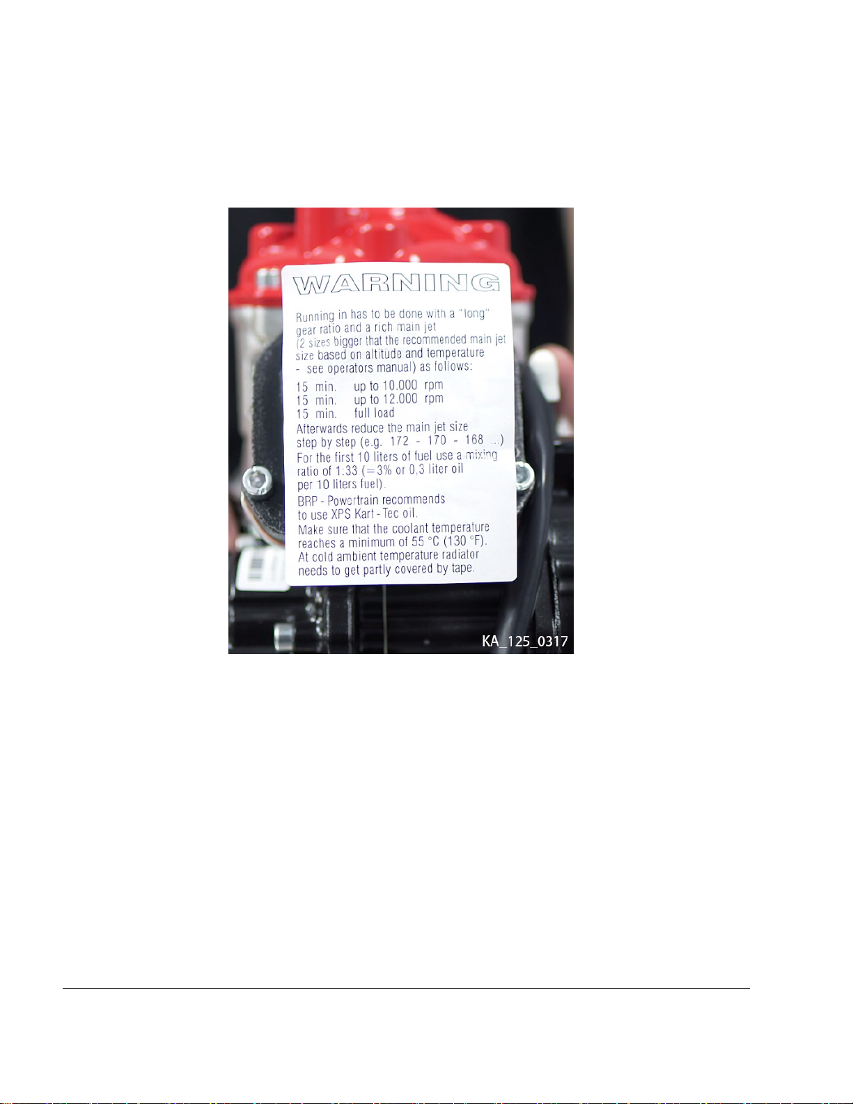
The information sticker is glued to the intake socket. It does not only prevent dust from
coming inside the engine during the transport, it also provides you with information about
the run-in procedure and general tasks you must do at the initial run of the engine.
Figure 1.4: Information sticker
Gear oil and fuel specifications
See the latest Operators Manual.
Equipment and modifications
Modifications to engine and/or equipment are not allowed.
INTRO
Page 8
Edition: September 01 2019
Effectivity: 125 MAX DD2 evo

BRP-Rotax
INSTALLATION MANUAL
Chapter: 1
ENGINE INSTALLATION
TOPICS IN THIS CHAPTER
Installation of overload clutch and engine with rear axle .........................................................................2
Engine installation with engine brackets .................................................................................................3
Direct attachment of the engine to chassis..............................................................................................5
Effectivity: 125 MAX DD2 evo
1
Page 1
Edition: September 01 2019

BRP-Rotax
INSTALLATION MANUAL
INSTALLATION OF OVERLOAD
CLUTCH AND ENGINE WITH REAR
AXLE
NOTE
The overload clutch is the link between the engine and the rear axle of the kart. In case that
the rear axle has been blocked by (e.g. breaking), the overload clutch is slipping slightly and
is not transferring the peak load from the rear
axle to the engine.
The plain bearings (pos. 2) are inside of the
overload clutch (pos. 1).
NOTE
Do not tighten the overload clutch and clamp
ring yet (see section Engine attachment with engine brackets).
Figure 2.1
Plain bearings
1 Overload clutch
Step
1
Procedure
Slide the clamp ring (pos. 1, following
figure ) the thrust washer (pos. 2) and
the overload clutch (3) to the middle of
the rear axle.
2
NOTE
The rear axle of the kart must have a smooth
surface (no grooves for keys) in the area of the
4 plain bearings of the overload clutch.
1
Page 2
Edition: September 01 2019
Figure 2.2: Overload clutch
Clamping ring
1
3 Overload clutch
5 Allen screw M5x30
2
Thrust washer
4
Allen screw M6x25
Effectivity: 125 MAX DD2 evo

BRP-Rotax
INSTALLATION MANUAL
ENGINE INSTALLATION WITH
ENGINE BRACKETS
Tools required:
• Allen key 8mm
• Allen key 5 mm
• Allen key 4 mm
• Torque wrench
See Figure: Tightening sequence and Engine
brackets.
The engine has to be fixed to the chassis by means
of 2 engine brackets (pos. 1). Due to different distances of the 2 main rails of various chassis brands, the
engine bracket is not included in the scope of supply.
Step
1
2 After engine alignment, tighten the 4
Procedure
Slide the engine onto the rear axle and
align the rear axle and the engine by
measuring the distance between the
front and the rear axle
Allen screws M8 x 25 to fix the upper
engine bracket to the engine with 28
Nm (20.65 ft. lb). Fix and tighten the
lower engine bracket to the upper
bracket with 4 Allen screws M8 x 30
with 22 Nm (16.22 ft. lb). Secure the
Allen screws with LOCTITE 243
blue.
NOTE
The minimum screw in length of the screws fixing the engine brackets onto the crankcase is
16 mm to 20 mm (0.6 - 0.95 in.).
Step
3
Procedure
Slide the overload clutch, thrust washer and clamp ring along the axle to the
hollow shaft and then fix to the rear
axle. Tighten the screw on the clamping ring with 10 Nm (89 in. lb).
Figure 2.3: Engine brackets
FIGURE SIMILAR
NOTE
The 125 MAX DD2 engine can only be mounted
on specially prepared chassis for this engine
type.
m WARNING
Non-compliance can result in serious injuries
or death!
For engine attachment to the chassis, please fol-
low the instruction of the chassis manufacturer.
Effectivity: 125 MAX DD2 evo
4
Tighten the 6 Allen screws (pos. 1, Figure Tightening sequence) on the overload clutch with 7 - 8 Nm (62 - 71 in.
lb). Make sure that every screw is
tightened with the right tightening torque, repeat procedure if necessary.
1
Page 3
Edition: September 01 2019

Figure 2.4: Tightening sequence
1 Allen screws
BRP-Rotax
INSTALLATION MANUAL
1
Page 4
Edition: September 01 2019
Effectivity: 125 MAX DD2 evo

BRP-Rotax
INSTALLATION MANUAL
DIRECT ATTACHMENT OF THE
ENGINE TO CHASSIS
If the frame of the chassis is specially prepared for installation of the ROTAX® 125 MAX DD2 evo, then 2
sheet metal brackets with holes are welded onto the
two frame tubes. The engine is clamped between the
two brackets with 4 bolts.
NOTE
The minimum screw in length of the screws fixing the engine brackets onto the crankcase is
16 mm to 20 mm (0.6 - 0.95 in.).
NOTE
Secure bolts with bolt adhesive e.g. LOCTITE
243.
Step
Procedure
Figure 2.5
Pick-up sensor
1
1 Mount engine directly on the brackets.
NOTE
Check for easy access to the pick-up sensor
(pos. 1). There are two options to install the
pick-up sensor. Choose the orientation which
gives you the best fit for your chassis
installation.
m WARNING
Non-compliance can result in serious injuries
or death!
For engine attachment to the chassis, please fol-
low the instruction of the chassis manufacturer.
Effectivity: 125 MAX DD2 evo
1
Page 5
Edition: September 01 2019

BRP-Rotax
INSTALLATION MANUAL
NOTES
Notes
Page 6
Edition: September 01 2019
Effectivity: 125 MAX DD2 evo
Edition /Rev. 0

BRP-Rotax
INSTALLATION MANUAL
Chapter: 2
FUEL SYSTEM
TOPICS IN THIS CHAPTER
Installation and connection of the fuel pump...........................................................................................2
Installation of the Bowden cable for carburetor control...........................................................................4
Installation and connection of the carburetor ..........................................................................................6
Effectivity: 125 MAX DD2 evo
2
Page 1
Edition: September 01 2019

BRP-Rotax
INSTALLATION MANUAL
INSTALLATION AND CONNECTION
OF THE FUEL PUMP
Tools required:
• Allen key 5 mm
• Circlip pliers
Step
1
Figure 3.1
Step
2
Procedure
The retaining plate, rubber buffers, fuel
pump, fuel hose (with 230 mm and
1800 mm length) is already preassembled.
Procedure
Install the retaining plate with fuel
pump (pos. 1) on the gearbox cover by
using 2 screws M6x30 (pos. 3) and
washers (pos. 2).
Figure 3.2
Fuel pump
1
3 Screws M6x30
Figure 3.3
TIP
Facilitate the assembly of fuel hose by
slightly widening the hose end with a pair
of circlip pliers.
2
Washer
ATTENTION
2
Page 2
Edition: September 01 2019
Fuel hose can be damaged!
Avoid excessive widening of the fuel hose.
Effectivity: 125 MAX DD2 evo

BRP-Rotax
INSTALLATION MANUAL
Step
Procedure
3
4
The fuel hose with 230 mm length will
be connected later to the carburetor,
see carburetor installation.
The larger fuel hose (pos. 1) should be
connected to the fuel filter (pos. 2) and
to the fuel tank.
Figure 3.4
Large fuel hose
1
ATTENTION
Pay attention to the direction of the arrow on
the fuel filter.
This must point towards the fuel pump.
ATTENTION
Route the fuel line from the fuel tank to the fuel fil-
ter so that it does not touch any moving parts of
the track and attach the fuel line onto the top side
of the chassis tube.
ATTENTION
The flow in the impulse hose and fuel lines
must not be restricted by the use of cable ties.
2
Fuel filter
Effectivity: 125 MAX DD2 evo
2
Page 3
Edition: September 01 2019

BRP-Rotax
INSTALLATION MANUAL
INSTALLATION OF THE BOWDEN
CABLE FOR CARBURETOR
CONTROL
Tools required:
• Open-end wrench 10 mm
Step
1
Reset spring of carb piston presses against
carburetor cover and might eject carburetor
Step
2 Remove nipple screw (pos. 5) with
3
4 Fit nipple screw in carburetor piston
5
Procedure
Carefully remove carburetor cover with
rubber ring (pos. 7, 8).
ATTENTION
cover at removal.
Procedure
open-end wrench 10 mm from carburetor piston (pos. 2).
Engage nipple of Bowden wire (pos. 9)
in nipple screw (pos. 5).
and hand tighten with open-end
wrench 10 mm.
Insert carburetor piston (pos. 2) into
carb body with recess of piston towards intake silencer.
Figure 3.5
1 Carburetor
3 Jet needle K57
Nipple screw
5
7 Carb cover
9 Bowden cable
Carburetor piston
2
Clip
4
Compression spring
6
Rubber ring
8
Restrictor (Mini, Micro
10
MAX evo)
6 Pass Bowden wire through compres-
sion spring (pos. 6) and through cover
with rubber ring (pos. 7, 8) of
carburetor.
7
8 Pass Bowden wire through Bowden
9 Connect Bowden cable to throttle
Fit carb cover (pos. 7) on carburetor.
conduit and through adjustment screw
on chassis (throttle pedal).
pedal.
2
Page 4
Edition: September 01 2019
NOTE
Shorten Bowden cable as required.
Step
10 Route carburetor Bowden cable on the
Procedure
top side of the chassis tubes and attach with the cable ties supplied. Make
sure that the Bowden cable does not
touch any moving parts or the track.
Effectivity: 125 MAX DD2 evo

BRP-Rotax
INSTALLATION MANUAL
m WARNING
Non-compliance can result in serious injuries
or death!
The carburetor Bowden cable must not be kinked
or restricted as the carburetor piston might get
stuck in full throttle position.
Step
11 Set and secure the adjustment screw
12 Set and secure the stop screw for
Procedure
for Bowden cable on chassis so that
the carburetor piston will remain in
closed position when throttle pedal is
not activated.
throttle pedal so that, with pedal completely pressed down, the carburetor
piston will be in the full open position.
The Bowden cable must not be under
full tension when the throttle is in fully
open position.
Effectivity: 125 MAX DD2 evo
2
Page 5
Edition: September 01 2019

BRP-Rotax
INSTALLATION MANUAL
INSTALLATION AND CONNECTION
OF THE CARBURETOR
Tools required:
• Ratchet wrench with socket 7 mm
• Phillips screwdriver
Step
1
2 Connect the outlet hose of the fuel
Procedure
Fit carburetor (pos. 1) into carburetor
socket and secure with hose clamp
(pos. 2) in vertical position.
pump with fuel inlet (pos. 3) on the
carburetor.
Figure 3.6
1 Carburetor
3 Fuel inlet
2
Page 6
Edition: September 01 2019
Hose clamp
2
Effectivity: 125 MAX DD2 evo

BRP-Rotax
INSTALLATION MANUAL
Chapter: 3
ELECTRIC SYSTEM
TOPICS IN THIS CHAPTER
Electric system overview.........................................................................................................................2
Installation ECU into the battery clamp assy............................................................................................3
Installation of the battery clamp assy. .....................................................................................................5
Installation of the wiring harness ............................................................................................................7
Effectivity: 125 MAX DD2 evo
3
Page 1
Edition: September 01 2019

INSTALLATION MANUAL
ELECTRIC SYSTEM OVERVIEW
BRP-Rotax
Figure 4.1
Connector pickup sensor
1
Connector battery
3
5 Connector ECU 6
7 Connector shift contact 8
Tie wrap 142x3.2
9
3
Page 2
Edition: September 01 2019
2 Connector starter
Connector RAVE (only applicable 125 MAX evo)
4
Connector ignition coil
Tie wrap 250x4.8
Effectivity: 125 MAX DD2 evo

INSTALLATION MANUAL
INSTALLATION ECU INTO THE
BATTERY CLAMP ASSY.
BRP-Rotax
Step
1 Prepare rubber pad (consists of two
Figure 4.2
Rubber pad
1
Procedure
halves) (pos. 1) and the ECU (pos. 2)
for installation.
2
ECU
Figure 4.3
Rubber pad
1
Step
3 Insert the complete unit into the battery
Procedure
clamp assy..
NOTE
Step
2
TIP
Effectivity: 125 MAX DD2 evo
Procedure
Install the rubber pad (pos. 1) onto the
ECU.
Align at the triangular bottom of the ECU.
It fits only in one position to the rubber
pad.
If difficulties at insertion occur, the inside of the
battery clamp assy. can be easily bent inward
so that the distance increases slightly.
ATTENTION
Make sure that the connection cable has been
installed between the two pads.
The connection of the ECU is on the rear side
(against the driving direction).
3
Page 3
Edition: September 01 2019

Figure 4.4
Rubber pad
1
BRP-Rotax
INSTALLATION MANUAL
2 Connection cable
3 ECU connector
3
Page 4
Edition: September 01 2019
Effectivity: 125 MAX DD2 evo

BRP-Rotax
INSTALLATION MANUAL
INSTALLATION OF THE BATTERY
CLAMP ASSY.
Tools required:
• Allen key 4 mm
• Ratchet wrench with socket 8 mm or Phillips
screwdriver
m WARNING
Non-compliance can result in serious injuries
or death!
Make absolutely sure to avoid short-circuiting of
battery terminals. A short circuit will ruin the bat-
tery and could cause an explosion.
Step
1
Procedure
Attach the battery fixture (pos. 5) with
the two pipe clamps (pos. 1 – 4) on the
left side box beside the driver’s seat.
NOTE
The clamps (pos. 2, 3) are designed for chassis
tubes of 30 - 32 mm (1.18 – 1.26 in) diameter.
ATTENTION
Risk of clamp fracture!
Do not over tighten the screw of the pipe clamps.
Step
2
3 Put the battery (pos. 7) into the fixture
Procedure
Install rubber pad (pos. 6) with battery
(pos. 7) into the battery holder (pos.
5).
and install the cover (pos. 8) with preassembled wiring harness using the
Allen screw with rounded flange head
(pos. 9).
Figure 4.5
Pipe clamps
1–4
Rubber pad
6
Battery cover
8
O-ring
10
Battery fixture
5
Battery
7
Flange head screw
9
Multiple function switch
11
TIP
The battery fixture (pos. 5) can be fixed
with one screw on one side of the clamp
(pos. 3).
Effectivity: 125 MAX DD2 evo
3
Page 5
Edition: September 01 2019

BRP-Rotax
INSTALLATION MANUAL
Figure 4.6
NOTE
The battery terminals must point in the direction
of the control unit.
Figure 4.8
Figure 4.7
Battery terminals
1
Step
3
Procedure
Connect the positive terminal (red) of
the battery.
Step
5
Procedure
Install the battery cover onto the battery holder.
NOTE
Make sure that the two retaining lugs (pos. 1)
are in the notches of the battery cover!
Step
6
Procedure
Tighten flange head screw (pos. 2) of
the battery cover.
4
Connect the negative terminal (black)
of the battery.
3
Page 6
Edition: September 01 2019
Figure 4.9
Retaining lugs
1
Flange head screw
2
Effectivity: 125 MAX DD2 evo

BRP-Rotax
INSTALLATION MANUAL
INSTALLATION OF THE WIRING
HARNESS
Tools required:
• Torx screwdriver T30
The wiring harness is delivered partly pre-assembled
to facilitate the installation. This means that the relay,
the master switch and the battery cover are already
pre-assembled and wired.
NOTE
The connector assignment is shown on the following pages. Details on the assignment of cables and pins are given in the wiring diagram.
NOTE
Cable lugs may break after repeated bending.
Step
1 Place the wiring harness loosely on
Procedure
the chassis.
NOTE
When unplugging connections on ignition pick
up and ignition coil, press the integrated catch
first.
NOTE
Disconnect any electrical plug connection only
by pulling on the plugs.
Step
2 Pre-mount cable tie large through the
Procedure
two holes provided on the mounting
plate.
NOTE
Always start the installation at the engine side to
work without tension on the wiring harness.
ATTENTION
Strain relief of the plug connections must be
ensured.
NOTE
Compensate excessive length of wiring harness
by routing cables in loops.
m WARNING
Non-compliance can result in serious injuries
or death!
The wiring harness must not touch moving
parts of the track.
Figure 4.10: Installation
1 Cable tie
Step
3
4 Fasten cables with cable ties on the
Procedure
Connect solenoid valve and ignition
coil. Attach both connectors (signed
green) on the two components.
mounting plate.
Effectivity: 125 MAX DD2 evo
3
Page 7
Edition: September 01 2019

BRP-Rotax
INSTALLATION MANUAL
Figure 4.11
1 Solenoid valve
Connectors (signed
3
green)
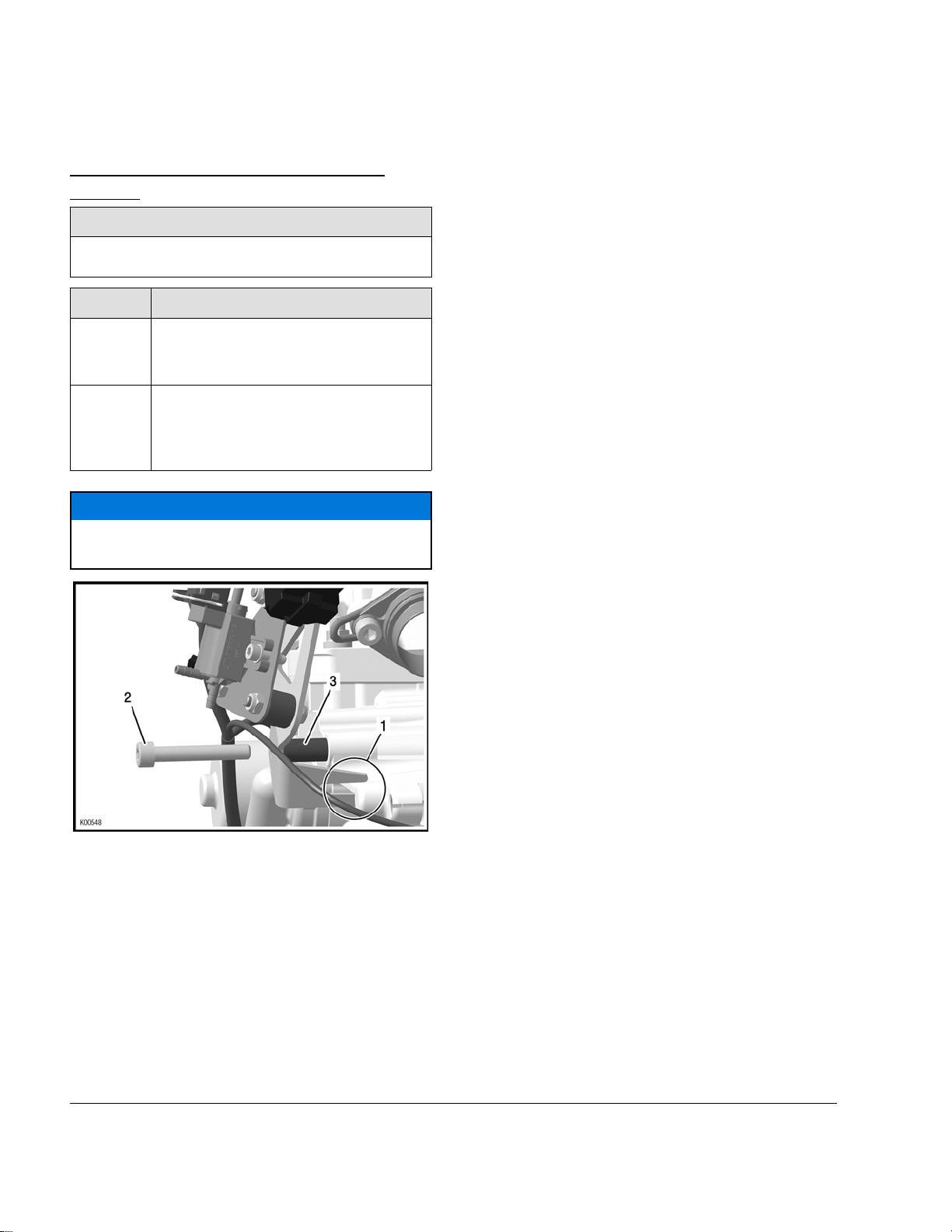
Step
5
Procedure
Remove isolation tape from the shift
contact wire (pos. 1) and loosely fasten with a tie wrap (pos. 2) (about 130
mm from the cable lug).
Ignition coil
2
4
Cable tie
Step
6
Procedure
Fasten the cable lug (pos. 3) to the
shift contact assy. using the Plastite
screw M6x25 (pos. 4). Pay attention to
correct sequence of the components!
See following Figures.
For correct adjusting of the plastite
screw find the according section inside
the latest Operators Manual.
NOTE
Fasten the cable lug (pos. 3) between the fuel
tube 8 mm (pos. 2) and the Plastite screw
M6x25 (pos. 4). See following Figure.
Figure 4.12
Tie wrap
1 Contact wire
2
NOTE
Do not tighten tie wrap yet in order to be able to
change its position later on.
3
Page 8
Edition: September 01 2019
Figure 4.13
Shift contact assy.
1
Cable lug
3
2
Fuel tube
4
Plastite screw M6x25
NOTE
The correct adjustment of the shift contact is described in the Operators Manual, section “Adjustment of gear shifting”.
Step
7
Procedure
Fasten the wire of the shift contact
assy. with a tie wrap (pos. 1) on the
bottom of the engine.
Effectivity: 125 MAX DD2 evo

BRP-Rotax
INSTALLATION MANUAL
Figure 4.14
Tie wrap
1
Step
8 Connect pick up connector to pick up
Procedure
sensor (pos. 1). Pay attention to the
engagement of the connector. See also section: Direct attachment of the
engine to chassis.
Step
9 Attach ignition cables to the spark
Procedure
plug.
Figure 4.15
Pick up sensor
1
NOTE
If it's not possible to plug in the connector of the
pick-up sensor, unscrew the pick-up sensor and
change the angle or direction. See also section:
Direct attachment of the engine to chassis.
Effectivity: 125 MAX DD2 evo
3
Page 9
Edition: September 01 2019

BRP-Rotax
INSTALLATION MANUAL
NOTES
Notes
Page 10
Edition: September 01 2019
Effectivity: 125 MAX DD2 evo
Edition /Rev. 0

BRP-Rotax
INSTALLATION MANUAL
Chapter: 4
COOLING SYSTEM
TOPICS IN THIS CHAPTER
Cooling system overview ........................................................................................................................2
Installation of the radiator .......................................................................................................................3
Intake silencer .........................................................................................................................................4
Installation of the intake silencer with integrated airfilter ........................................................................5
Effectivity: 125 MAX DD2 evo
4
Page 1
Edition: September 01 2019

INSTALLATION MANUAL
COOLING SYSTEM OVERVIEW
BRP-Rotax
Figure 5.1
1 Radiator 2
3 Lower coolant water hose 4
Rubber puffer
5
7 Washer 8 Lock nut
Allen screw — rounded flange head
9
4
Page 2
Edition: September 01 2019
Upper coolant water hose
Clamp 16–25
Rubber puffer
6
Hose clamps
10
Effectivity: 125 MAX DD2 evo

BRP-Rotax
INSTALLATION MANUAL
INSTALLATION OF THE RADIATOR
Tools required:
• Ratchet wrench with socket 7 mm or Phillips
screwdriver
Step
1
2 Mount the radiator support with the
NOTE
For an optimum of cooling efficiency, we recommend to install the radiator in an angle of 25° +/5° tilted backwards.
Non-compliance can result in serious injuries
For radiator installation to the chassis, please fol-
low the instruction of the chassis manufacturer.
Step
3 Put the four supplied hose clamps
Procedure
Mount radiator (pos. 1) using the provided rubber buffer (pos. 5) and lock
nut (pos. 8) with washer (pos. 7) on
the lower support bracket on the
chassis.
rubber buffer (pos. 6) and lock nut
(pos. 8) with washer (pos. 7) on the
upper radiator mount and onto the
chassis.
m WARNING
or death!
Procedure
(pos. 10) on the coolant hoses.
Step
6 Secure the coolant hoses with the
7
The coolant water hose between radiator and
engine must not rub with the drivers seat.
Arrange the routing of the coolant water hose
Step
8 Secure the lower coolant water hose
Non-compliance can result in serious injuries
Please follow the instruction of the chassis manu-
facturer for mounting the lower coolant water hose
Step
9 Establish connection between over-
Procedure
hose clamps (pos. 10).
Secure the upper coolant water hose
to the driver's seat (pos. 2) using the
provided cable tie.
ATTENTION
accordingly.
Procedure
(pos. 3) using two of the provided cable ties to the chassis.
m WARNING
or death!
to the chassis.
Procedure
flow socket on radiator filling socket
and the overflow bottle with an appropriate piece of hose.
4 Push the upper coolant water hose
(pos. 2) onto the upper socket of the
radiator as well onto water socket of
the cylinder head cover.
5
Effectivity: 125 MAX DD2 evo
Push the lower coolant water hose
(pos. 3) onto the lower socket of the
radiator as well onto the water socket
of the water pump housing.
ATTENTION
Warrant the best possible engine cooling.
Ensure that the air stream covers the complete ra-
diator area.
4
Page 3
Edition: September 01 2019

INTAKE SILENCER
BRP-Rotax
INSTALLATION MANUAL
Figure 5.2: Overview
1 Intake silencer case 2 Intake silencer cover
3 Filter element 4 Holder for filter element
5 Intake silencer tube 6
7 Carburetor socket 8
9 Lock nut M6 10
O-ring
Clamp 50–70
Allen screww. rounded flange head
4
Page 4
Edition: September 01 2019
Effectivity: 125 MAX DD2 evo

INSTALLATION MANUAL
INSTALLATION OF THE INTAKE
SILENCER WITH INTEGRATED
AIRFILTER
Tools required:
• Allen key 4 mm
• Ratchet wrench with socket 7 mm or Phillips
screwdriver
BRP-Rotax
Step
1 Install the rubber intake pipe (pos. 5)
2
3
4
5
Procedure
in a vertical position into the bottom
half (pos. 2) of the intake silencer so
that the rounded intake openings point
outwards.
Fit the carburetor socket (pos. 7) into
the inner side half of silencer (pos. 1)
so that the arrow on the socket points
towards the carburetor.
Install the filter element (pos. 3) with
holder (pos. 4).
Assemble filter box and filter insert as
shown in the intake silencer overview
figure. Make sure that the locking is interlocked properly.
Attach the intake silencer with the supplied hose clamps (pos. 8) to the
carburetor.
NOTE
The carburetor socket (pos. 7) is slightly tilted in
one direction and can be turned so that the best
possible position between carburetor and intake
silencer can be achieved.
Step
6 Attach the intake silencer on the chas-
Effectivity: 125 MAX DD2 evo
Procedure
sis using the M6 Allen screw with
rounded flange head (pos. 10).
4
Page 5
Edition: September 01 2019

BRP-Rotax
INSTALLATION MANUAL
NOTES
Notes
Page 6
Edition: September 01 2019
Effectivity: 125 MAX DD2 evo
Edition /Rev. 0

BRP-Rotax
INSTALLATION MANUAL
Chapter: 5
EXHAUST SYSTEM
TOPICS IN THIS CHAPTER
Exhaust system overview........................................................................................................................2
Installation of the exhaust system ...........................................................................................................3
Effectivity: 125 MAX DD2 evo
5
Page 1
Edition: September 01 2019

INSTALLATION MANUAL
EXHAUST SYSTEM OVERVIEW
BRP-Rotax
Figure 6.1
Exhaust system
1
Tension spring
3
Exhaust gasket
5
7 Rubber buffer 8
9 Rubber buffer 10 Washer 8.4
11 Lock nut M8 12
Exhaust gasket
13
2
4
6
14
5
Page 2
Edition: September 01 2019
Silencer assy.
Spring stainless
Retaining plate
Spring stainless
Exhaust socket assy.
Spring stainless
Effectivity: 125 MAX DD2 evo

BRP-Rotax
INSTALLATION MANUAL
INSTALLATION OF THE EXHAUST
SYSTEM
Tools required:
• Open-end wrench 13 mm
• Spring hook
NOTE
On the underside of the exhaust system, two different mounting mechanisms are provided. At
the front, the assembly is carried out with rubber
buffers (pos. 7) between the retaining plate
(pos. 6) and the exhaust system and attached
by extension springs (pos. 8). At the rear, the
exhaust system is mounted directly using a rubber mount M8 (pos. 9).
ATTENTION
A rigid suspension of the exhaust system
could result in fractures in the exhaust system.
NOTE
For easier installation use the special tool
"Spring hook" part no. 251680.
ATTENTION
Do not over-stress the springs when fitting
them.
Step
5 Attach the exhaust system on the
Procedure
chassis supports such that the sealing
of the ball joint between cylinder and
exhaust system will not be impaired.
Step
1 Attach the heat-resistant rubber mount
2
3
Step
4
Procedure
(pos. 9) to the support lug on the
underside of the exhaust.
Arrange the chassis-specific supports
so that the exhaust system follows the
straightest possible course from the
exhaust socket on the cylinder to the
muffler.
The gasket (pos. 13) is the only sealing between engine and the exhaust
system. Additional heat-resistant LOCTITE is not necessary anymore.
Procedure
Secure the exhaust system on the exhaust socket using the two supplied
exhaust springs (pos. 14).
Effectivity: 125 MAX DD2 evo
5
Page 3
Edition: September 01 2019

BRP-Rotax
INSTALLATION MANUAL
NOTES
Notes
Page 4
Edition: September 01 2019
Effectivity: 125 MAX DD2 evo
Edition /Rev. 0

BRP-Rotax
INSTALLATION MANUAL
Chapter: 6
INSTALLATION OF THE ACCESSORIES
TOPICS IN THIS CHAPTER
Installation of mounting plate ..................................................................................................................2
Fitting of the spark plug...........................................................................................................................3
Installation and connection of the RAVE control unit ..............................................................................4
Assembly of paddle shift system.............................................................................................................7
Effectivity: 125 MAX DD2 evo
6
Page 1
Edition: September 01 2019
INSTALLATION MANUAL
INSTALLATION OF MOUNTING
PLATE
Tools required:
• Allen key 6 mm
BRP-Rotax
Step
1 The holding bracket, the mounting
2 Install whole bracket kit with Allen
Slot of mounting plate has to be installed in
Procedure
plate, the solenoid valve and the ignition coil are already pre-assembled.
screw M8x50 (pos. 2) and distance
sleeve 8.2/12/25.5 (pos. 3) onto the
engine.
ATTENTION
the correct position.
Figure 7.1
2
1 Slot
Distance sleeve 8.2/
3
12/25.5
Allen screw M8x50
NOTE
Distance sleeve (pos. 3) has to be install between engine housing and retaining plate. Distance sleeve can be replaced by fitting of an
additional seat stay.
6
Page 2
Edition: September 01 2019
Effectivity: 125 MAX DD2 evo

INSTALLATION MANUAL
FITTING OF THE SPARK PLUG
The engine will be supplied with a spark plug.
Tools required:
• Feeler gauge
• Socket 21 mm
• Torque wrench
BRP-Rotax
Step
1 Remove the transport plug from the
2
Procedure
cylinder head.
Check electrode gap of spark plug. Adjust as required.
NOTE
Check technical regulations to assure conformity when setting the electrode gap.
Step
3 Fit supplied spark plug (pos. 1) and
4
Procedure
tighten 25 Nm (221 lbf in) to 27 Nm
(239 lbf in).
Install the spark plug connector (pos.
2), ensure correct engagement.
Figure 7.2
Spark plug
1
Spark plug connector
2
Effectivity: 125 MAX DD2 evo
6
Page 3
Edition: September 01 2019

BRP-Rotax
INSTALLATION MANUAL
INSTALLATION AND CONNECTION
OF THE RAVE CONTROL UNIT
NOTE
The hose package of the RAVE control is already pre-assembled.
NOTE
The impulse restrictor is offered optionally.
Step
1
Procedure
Insert impulse nozzle (pos. 6) about 25
mm into the 420 mm pressure line
(pos. 7) using an Allen key SW4. Pay
attention to the mounting direction! It
also works without an impulse nozzle,
this only serves to choke the opening
of the exhaust valve.
NOTE
In order to prevent the displacement of the impulse nozzle (pos. 6), a small cable tie (pos. 8)
should be attached directly afterwards to the
pressure line. Do not tie up the pressure line
completely!
Figure 7.3
4 Check valve
7 Pressure line
Step
2
Impulse nozzle
6
Tie wrap small
8
Procedure
Attach the black hose of the hose
package (pos. 1) to the metal connector (pos. 2) of the magnetic valve
6
Page 4
Edition: September 01 2019
Figure 7.4
Hose package
1
Step
3
2
Metal connector
Procedure
Attach the other end of the hose package (pos. 1) (short end with T-piece) to
the fuel pump.
Effectivity: 125 MAX DD2 evo

BRP-Rotax
INSTALLATION MANUAL
Figure 7.5
Hose package
1
Step
4
Procedure
Attach the fuel line of the hose package (pos. 1) to the impulse nipple on
the engine housing..
NOTE
Check that valve is not the lowest point of the
impulse circuit to prevent that condensation affects a proper operation.
Step
5
Figure 7.7
1 Cable tie
Step
6
Procedure
Attach cable tie with mount (pos. 1) to
the housing.
Impulse nipple
2
Procedure
Secure both lines with cable tie, ensuring that the black hose is on top.
Figure 7.6
Hose package
1
Effectivity: 125 MAX DD2 evo
ATTENTION
Do not tighten cable ties too tight, because
constricted lines can lead to loss of function.
Step
7
Procedure
Attach an additional cable tie (pos. 3)
as shown in figure.
Edition: September 01 2019
6
Page 5

Figure 7.8: Cable tie
1 Cable tie
3 Cable tie
2
Black hose
BRP-Rotax
INSTALLATION MANUAL
Step
8
Figure 7.9
Procedure
Attach the 220 mm pressure line (pos.
1) to the magnetic valve (pos. 3). Secure the pressure line on the magnetic
valve with a tie wrap (pos. 4). Attach
the other end of the pressure line to
the exhaust valve (pos. 2).
1 Pressure line
Magnetic valve
3
6
Page 6
Edition: September 01 2019
2
Exhaust valve
4
Cable tie
Effectivity: 125 MAX DD2 evo

INSTALLATION MANUAL
ASSEMBLY OF PADDLE SHIFT
SYSTEM
Tools required:
• Allen key 6 mm
• Allen key 5 mm
BRP-Rotax
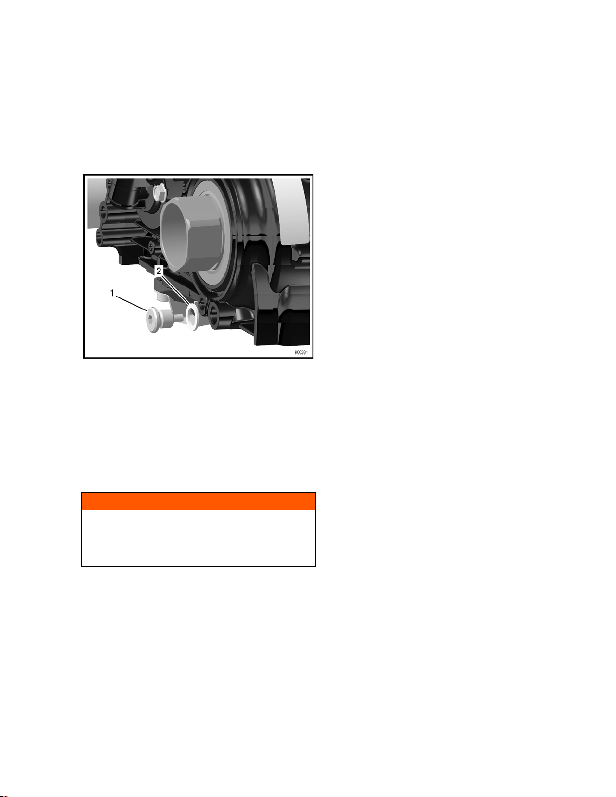
Step
1 Install spacer (pos. 1) into the appro-
Figure 7.10
Spacer
1
Procedure
priate bore (pos. 2) of the engine
housing.
Appropriate bore
2
Figure 7.11
2
1 Washer
Step
3 Mount Bowden cable (pos. 2) with
Procedure
washer (pos. 1) onto the shift contact
guidance (pos. 3).
Bowden cable
Step
2
Effectivity: 125 MAX DD2 evo
Procedure
Install washer (pos. 1) on one of the
two Bowden cables (pos. 2).
Figure 7.12
1 Washer
Shift contact
3
guidance
Step
4
2
Bowden cable
Procedure
Mount Bowden cable with shift contact
guidance (pos. 1) to the retaining plate
(pos. 2).
Page 7
Edition: September 01 2019
6

Figure 7.13
BRP-Rotax
INSTALLATION MANUAL
Shift contact
1
guidance
Step
5
Figure 7.14
Retaining plate
2
Procedure
Mount Allen screw (pos. 1), lock washer (pos. 2) and spacer (pos. 3) together with the shift contact guidance (pos.
4) to the engine housing. Tightening
torque 22 Nm.
Figure 7.15
1 Point 1
Step
7
Figure 7.16
2
Point 2
Procedure
Mount sleeve (pos. 1) onto the retaining plate (pos. 2).
2
1 Allen screw
Spacer
3
Step
Procedure
Lock washer
Shift contact guidance
4
6 The alignment between point -1- and
point -2- must be given. Otherwise it
can cause increased friction, which
has a negative impact on shifting
behavior.
6
Page 8
Edition: September 01 2019
1 Mount sleeve
Step
8
Procedure
Mount second Bowden cable (pos. 1)
through shift contact guidance and
sleeve onto the retaining plate (pos.
2).
No washer is necessary on this Bowden cable.
Retaining plate
2
Effectivity: 125 MAX DD2 evo

BRP-Rotax
INSTALLATION MANUAL
Figure 7.17
1 Bowden cable
3 Guidance
Step
9
Retaining plate
2
Procedure
Install Bowden cables (pos. 1) into the
support on the back of the engine.
Figure 7.19
Cable support
1 Bowden cables
3 Set screw
Step
11 Hand-tighten both Bowden cables
Procedure
(pos. 1) onto the control whip (pos. 2),
using M6. Allen screws (pos. 3) and
washers (pos. 4). Pay attention to the
correct installation of the control whip!
2
NOTE
The oblique millings (pos. 5) of the control whip
serve to guide the cables. The cable ends must
look away from the center of the control whip.
The Bowden cables can be attached to the control
whip in two different ways:
• Version 1:
Figure 7.18
1 Bowden cable
Step
10
Effectivity: 125 MAX DD2 evo
Procedure
Thread both ends of the Bowden cables (pos. 1) through the cable support
(pos. 2). Install the set screw (pos. 3)
onto the cable support – just pre-assemble it, do not tighten yet.
Fasten Bowden cable to position 5 inside.
Feature: Shift travel longer, but less effort.
• Version 2
Fasten Bowden cable to position 5 outside.
Feature: Short shift, but higher effort.
6
Page 9
Edition: September 01 2019

BRP-Rotax
INSTALLATION MANUAL
NOTE
The control lever can also be attached on the
back, depending on how it is more ergonomic
for the driver.
Figure 7.20
Control whip
1 Bowden cable
3 Allen screw
Oblique millings
5
Step
12 Hand-tighten control lever left and right
Procedure
(pos. 1) onto the control whip (pos. 4),
using M6 Allen screws (pos. 2) and
washers (pos. 3).
2
4
Washer
Step
13
Procedure
Install spacer (pos. 1) with washer
(pos. 2) onto the bottom side of the
control whip (3).
NOTE
The bottom side is, where the screws of the
Bowden cables are fixed.
Figure 7.21
1 Control lever
3 Washer
6
Page 10
Edition: September 01 2019
2
Allen screw
Control whip
4
Figure 7.22
Spacer
1
Control whip
3
Step
14 Tighten Allen screw M6x60 (pos. 1)
Procedure
and washer (pos. 2) onto the top of the
control whip (pos. 3).
2
Thrust washer
NOTE
Top is the opposite side, where the screws of
the Bowden cables are attached.
Effectivity: 125 MAX DD2 evo

BRP-Rotax
INSTALLATION MANUAL
Figure 7.23
2
1 Allen screw M6x60
Control whip
3
Step
15
Procedure
Place the entire shifting unit onto the
steering wheel and tighten it using Allen screw M6x 60 (pos. 3), M6 lock nut
(pos. 1) with washer (pos. 2).
Washer
NOTE
Control whip must run smoothly.
NOTE
Spacer must fit into the bore provided on the
steering wheel.
Figure 7.24
2
1 Lock nut M6
3 Allen screw M6x60
Step
16 The setting of the shifting is carried out
17
Procedure
in neutral gear, which means that the
control whip must be in horizontal
position.
Tighten screw (pos. 2) of the cable
abutment (pos. 1) and the screws of
the Bowden cables on the control whip
(pos. 3).
Washer
NOTE
At full steering angle, no gear must engage. If a
gear engages by itself, the distance between
control whip and cable abutment must be
adjusted.
Effectivity: 125 MAX DD2 evo
Step
18
Procedure
Finally, the length of the Bowden cables can be adjusted so that they do
not disturb the driver when shifting.
6
Page 11
Edition: September 01 2019

BRP-Rotax
INSTALLATION MANUAL
Figure 7.25
1 Cable abutment
Control whip
3
2
Screw
6
Page 12
Edition: September 01 2019
Effectivity: 125 MAX DD2 evo

BRP-Rotax
INSTALLATION MANUAL
Chapter: 7
FINISHING WORK
TOPICS IN THIS CHAPTER
Check oil level in gearbox........................................................................................................................2
Venting of the gear compartment ............................................................................................................4
NOTE
To determine the best possible transmission ratio, the use of a rev-counter is required for observation
of the speed limits.
NOTE
To warrant engine operation within temperature limits of the coolant, a temperature sensor for
observation of the coolant temperature is required.
NOTE
Refer to Operators Manual for operating limits.
Effectivity: 125 MAX DD2 evo
7
Page 1
Edition: September 01 2019

BRP-Rotax
INSTALLATION MANUAL
CHECK OIL LEVEL IN GEARBOX
The gearbox is already filled with the appropriate
amount of oil by the engine manufacturer. However,
before the engine is installed in the frame, the oil level must be verified or replenished.
Step
1 Place engine on a horizontal surface
When placing the engine on a horizontal sur-
face, take care not to damage the crankcase
sensor, which is mounted on the bottom of the
Step
2 The oil level can be checked on in-
Procedure
and/or assembling trestle.
ATTENTION
crankcase.
Procedure
spection glass (pos. 1). It should reach
approximately to one-third of the inspection glass, see following figure. If
the oil level is not sufficient, replenish
oil as described in the following steps.
NOTE
For gearbox oil specifications and oil capacity
(total) see the latest Operators Manual.
Figure 8.1
Inspection glass
1
Step
3 Remove the air vent screw (pos. 1)
4
Procedure
and slowly fill in oil until oil level is in
the middle of the inspection glass.
Hand-tighten air vent screw (pos. 1).
7
Page 2
Edition: September 01 2019
Figure 8.2
1 Air vent screw
Effectivity: 125 MAX DD2 evo
BRP-Rotax
INSTALLATION MANUAL
NOTE
For draining the oil from the gear case, remove
the magnetic oil drain plug (pos. 1) and sealing
ring (pos. 2). Clean the oil drain plug before installation. Always use a new sealing ring.
Figure 8.3
Magnetic oil drain
1
plug
Sealing ring
2
NOTE
Tighten magnetic oil drain plug (pos. 1) to 20
Nm (177 lbf.in.).
m WARNING
Non-compliance can result in serious injuries
or death!
Do not run the engine without gear oil. This will
lead to engine failure.
Effectivity: 125 MAX DD2 evo
7
Page 3
Edition: September 01 2019

VENTING OF THE GEAR
COMPARTMENT
BRP-Rotax
INSTALLATION MANUAL
Step
1
2 Establish a connection between the
Procedure
Remove cap from the venting screw.
venting screw and a collecting reservoir using a piece of the supplied fuel
hose of an appropriate length.
NOTE
The venting hose must not reach all the way to
the bottom of the collecting reservoir.
ATTENTION
Do not attach the venting hose on the bottom
of the collecting reservoir, if only one reservoir
is in use.
7
Page 4
Edition: September 01 2019
Effectivity: 125 MAX DD2 evo

Index
BRP-Rotax
INSTALLATION MANUAL
B
Battery, installation ................................................5
Bowden cable, installation......................................4
C
Carburetor, connection ..........................................6
Carburetor, installation...........................................6
Cooling system .....................................................1
Cooling system overview .......................................2
D
Direct attachment of the engine to chassis ..............5
E
ECU, Installation ...................................................3
Electric system......................................................1
Electric system overview........................................2
Engine information ................................................4
Engine, installation ................................................3
Exhaust system ....................................................1
Exhaust system overview ......................................2
Exhaust system, installation ...................................3
O
Oil level, check in gearbox .....................................2
Overload clutch, installation ...................................2
P
Paddle shift system, assembly ...............................7
R
Radiator, installation ..............................................3
RAVE control unit, installation ................................4
S
Spark plug, fitting ..................................................3
U
Unboxing..............................................................1
V
Venting of the gear compartment............................4
F
Finishing work.......................................................1
Fuel pump, connection ..........................................2
Fuel pump, installation...........................................2
Fuel system, installation ........................................1
I
Intake silencer ......................................................4
Intake silencer, installation .....................................5
INTRO .................................................................1
M
Mounting plate, installation.....................................2
Effectivity: 125 MAX DD2 evo
W
Wiring harness, installation ....................................7
Index
Page 5
Edition: September 01 2019

Operator‘s Manual

BRP-Rotax
Operators Manual
Table of Content
Chapter INTRO – GENERAL INFORMATION
Chapter 1 – Technical Description
Chapter 2 – Operating fluids and battery
Chapter 3 – Engine calibration
Chapter 4 – Engine operation
Chapter 5 – Preservation and transport
Effectivity: 125 MAX DD2 evo
Content
Page 1
Edition: September 01 2019

BRP-Rotax
Operators Manual
NOTES
Page 2
Edition: September 01 2019
Effectivity: 125 MAX DD2 evo

BRP-Rotax
Operators Manual
Chapter: INTRO
GENERAL INFORMATION
Preface Before operating the engine, read the Operators Manual carefully.
If any passages of the Manual are not clearly understood or if you have questions, please
contact an authorized Distribution or Service Center for ROTAX®-kart engines.
This document and all technical data and procedures therein are property of BRP-Rotax
GmbH & Co KG and based on the state of knowledge at the time of publication The
Manual has been drawn up to the best of our knowledge. However, excluding any liability.
We reserve all rights including technical modification and possibility of errors. Reprinting,
translation or copies in whole or in part, are authorized only after written permission by
BRP-Rotax GmbH & Co KG.
BRP-Rotax GmbH & Co KG reserves the right at any time to discontinue or change
specifications, prices, designs, features, models or equipment without incurring obligation.
Engine performance may vary depending on, among other things, general conditions,
ambient temperature and altitude.
Contents This Operators Manual contains instructions about how to operate the ROTAX®-Engine
Type 125 MAX DD2 evo.
Symbols used This Manual uses the following symbols to emphasize particular information. This
information is important and must be observed.
m WARNING
Identifies an instruction, which if not followed may cause injury or endanger the
life of the driver, mechanic or third party.
ATTENTION
Denotes an instruction which if not followed may severely damage the engine.
Noncompliance might lead to health hazards under certain conditions.
ENVIRONMENTAL NOTE
Environmental notes give you tips on environmental protection.
NOTE
Indicates supplementary information which may be needed to fully complete or
understand an instruction.
✔
TIP
______________________________________________________
Denotes a checking operation
This information gives you additional advice and tips
Effectivity: 125 MAX DD2 evo
INTRO
Page 1
Edition: September 01 2019

BRP-Rotax
Operators Manual
NOTES
Page 2
Edition: September 01 2019
Effectivity: 125 MAX DD2 evo

BRP-Rotax
Operators Manual
Chapter: 1
TECHNICAL DESCRIPTION
TOPICS IN THIS CHAPTER
Design of the ROTAX engine 125 MAX DD2 evo.......................................................................................2
General ................................................................................................................................................2
Cooling circuit .......................................................................................................................................2
Balance gear.........................................................................................................................................3
Ignition unit ...........................................................................................................................................3
Electric starter .......................................................................................................................................3
Electro pneumatically exhaust timing control ...........................................................................................3
Intake silencer.......................................................................................................................................3
Exhaust system.....................................................................................................................................4
Gearbox ...............................................................................................................................................4
Electronic Shifting Assistant (ESA) .........................................................................................................4
Fuel pump ............................................................................................................................................4
Carburetor ............................................................................................................................................4
Centrifugal clutch ..................................................................................................................................5
Overload clutch .....................................................................................................................................5
Effectivity: 125 MAX DD2 evo
1
Page 1
Edition: September 01 2019

BRP-Rotax
Operators Manual
DESIGN OF THE ROTAX ENGINE 125 MAX DD2 EVO
Figure 1.1
GENERAL
The Rotax 125 MAX DD2 evo engine is a single cylinder two stroke engine with reed valve
controlled inlet and 125 cm
the gasoline in a specified mixing ratio.
The power transmission to the rear axle takes place via a manually shift able integrated 2speed gearbox.
________________________________________________________________
COOLING CIRCUIT
The coolant is pumped from the radiator to the water pump which is driven by the clutch
shaft. The water pump conveys the coolant through cylinder and the cylinder head back to
the radiator.
The cooling circuit is equipped with a thermostat (opening point 45 °C / 113 °F). It assures
that the engine reaches its operating temperature quickly and keeps it at a relatively constant level.
The thermostat is integrated in the cylinder head cover.
________________________________________________________________
3
displacement. Mixture lubrication is achieved by adding oil to
1
Page 2
Edition: September 01 2019
Effectivity: 125 MAX DD2 evo

BALANCE GEAR
IGNITION UNIT
BRP-Rotax
Operators Manual
The balance gear is mounted on the primary shaft and rotates counter-wise to the crankshaft to reduce engine vibration.
________________________________________________________________
The control of the ignition system is exercised by the ECU (Engine Control Unit). To calculate the ignition timing, an engine speed sensor is needed, which is installed on the bottom
of the engine housing. There is no manual adjustment of the ignition system necessary
and/or possible.
If the power button is pressed once, the ignition is activated and the button lights up. To
start the engine, it only needs to be pressed once again. To turn off the engine as well as
the ignition, proceed in reverse order.
________________________________________________________________
ELECTRIC STARTER
By pressing the "START" button, the circuit between the battery and the electric starter will
be closed by a relay. The electric starter drives the starter gear on the crankshaft via an intermediate gear with free wheeling, until the engine starts to run. An automatic switch reset from "START" to "ON" is integrated.
________________________________________________________________
ELECTRO PNEUMATICALLY EXHAUST TIMING CONTROL
The engine type 125 MAX DD2 evo is equipped with an electro-pneumatic exhaust control. The E-RAVE (Electronic ROTAX Adjustable Variable Exhaust) system is controlled by
an electro-pneumatic valve via the ECU. The vacuum required is provided by the engine
crankcase.
If the engine is running at idle speed or below the opening point of the E-RAVE system
(between approximately 8000-9000 rpm) the exhaust valve is closed. With the engine running, it closes or opens the electro-pneumatic valve of the exhaust depending on the
speed and, therefore it provides optimum performance characteristics.
________________________________________________________________
INTAKE SILENCER
The intake silencer incorporates an air filter to clean the intake air. The intake silencer has
been designed for optimum reduction of air intake noise level and represents a tuned system with the engine.
The air filter consists of several layers and has been optimized in the area of air passage
and filter efficiency. If soiled or during engine maintenance work, clean the filter with biodegradable products.
Effectivity: 125 MAX DD2 evo
1
Page 3
Edition: September 01 2019

________________________________________________________________
EXHAUST SYSTEM
The exhaust system is designed as resonance system with an after-muffler and represents a tuned system with engine.
________________________________________________________________
GEARBOX
The power transmission to the rear axle takes place via manually shiftable integrated 2speed gearbox and not as usual, via a maintenance intensive chain drive. Changing the
gear activates the gear shift fork as well as a shifting sleeve, which slides on the hollow
shaft between the 1
BRP-Rotax
Operators Manual
st
and 2ndgear and then engages in the respective idle gear.
The gear is kept in position by an index pin, which keeps the gearshift fork in the selected
position, 1
To allow shifting into 2
off for a moment when actuating the shifting paddle.
________________________________________________________________
st
gear, neutral or 2ndgear.
nd
gear without lifting the foot from the gas pedal, the ignition is cut
ELECTRONIC SHIFTING ASSISTANT (ESA)
To optimize the shifting from 1stto 2ndgear, the ignition is interrupted for a short time. This
releases load from the gearset and, gear shifting is faster and less stressful for the
gearset.
________________________________________________________________
FUEL PUMP
The fuel pump functions due to the alternating negative pressure and overpressure in the
crankcase and sucks fuel from the fuel tank into the carburetor via the fuel pump.
In the suction side of the fuel pump (between fuel tank and fuel pump) a fuel filter is installed to prevent contamination of the fuel pump and carburetor.
________________________________________________________________
CARBURETOR
The carburetor (DELL’ORTO VHSB 34) is a slide type carburetor with float system. The
standard main jet is suitable for almost all operating conditions. For extreme operating
conditions, the main jet size must be adjusted to the actual conditions according to this
manual.
1
Page 4
Edition: September 01 2019
________________________________________________________________
Effectivity: 125 MAX DD2 evo

CENTRIFUGAL CLUTCH
The engine is equipped with a centrifugal clutch operating in an oil bath. This clutch separates the engine from the gearbox at less than 2.500 rpm. Only at an engine speed of approx. 4.000 rpm. the centrifugal clutch is completely engaged.
________________________________________________________________
OVERLOAD CLUTCH
The engine has a mechanical overload clutch, which is installed on the rear axle. It is to
protect the crankshaft from hard shocks from the drive components which are not usual
during normal operation (e.g. the blocking of the rear axle).
BRP-Rotax
Operators Manual
Effectivity: 125 MAX DD2 evo
1
Page 5
Edition: September 01 2019

BRP-Rotax
Operators Manual
NOTES
Page 6
Edition: September 01 2019
Effectivity: 125 MAX DD2 evo

BRP-Rotax
Operators Manual
Chapter: 2
OPERATING FLUIDS AND BATTERY
TOPICS IN THIS CHAPTER
Coolant....................................................................................................................................................2
Battery.....................................................................................................................................................3
Battery charging unit ...............................................................................................................................4
Fuel .........................................................................................................................................................6
See also table “important information (summary)” in Chapter 5.
Effectivity: 125 MAX DD2 evo
2
Page 1
Edition: September 01 2019

BRP-Rotax
Operators Manual
COOLANT
Use only distilled water as engine coolant. If the kart is stored below the freezing temperature of water, make sure to drain the water from the cooling radiator and engine
completely.
Step
1
2 Close radiator cap.
Storage below the freezing temperature of water could lead to a damage of the cooling
______________________________________________________
Procedure
Open radiator cap and fill the system with coolant.
Small radiator: approx. 0.52 liter / 0.137 gal for the complete cooling system
Big radiator: approx. 0.7 liter / 0.185 gal for the complete cooling system
ATTENTION
Observe the storage conditions.
system and the engine.
ATTENTION
Exceeding the engine temperature could lead to serious engine failure.
The engine temperature should not exceed 85 °C / 185 °F.
2
Page 2
Edition: September 01 2019
Effectivity: 125 MAX DD2 evo

BRP-Rotax
Operators Manual
BATTERY
See Fig. Pos. 1: Charging connector.
The power for the ignition unit and electric starter is only supplied from the battery. With a
fully charged battery of 12 V and 6.5 Ah, the engine can be started approximately one hundred times and operated over a period of approximately five hours. With the battery voltage decreasing to approximately 11 V the point will be reached when the battery voltage
is too low to generate a spark for ignition.
ATTENTION
The lifespan of the battery will be drastically reduced by exhausting the battery
completely.
Fully re-charge the battery before and after any operation of the kart.
NOTE
It is recommended to always carry a charged spare battery. The installed battery
should be replaced with a fully charged battery before it is completely exhausted.
NOTE
If the spark plug is removed, to check if the battery still generates a spark, consider the following: with the spark plug removed it is easier for the electric starter to
crank the engine, which reduces current absorption of the electric starter, resulting in battery voltage adequate to generate a spark. If the spark plug is fitted
again, it may happen that the engine does not start.
NOTE
To charge a battery, the delivered battery charging unit specified by ROTAX®
should be utilized (battery charger part no. 265148). When using the lithium battery available as spare part, the battery charger Optimate Lithium (part no.
581325) is mandatory.
NOTE
To be able to use the battery charger in your home country, please contact your
nearest authorized ROTAX® distributor or one of their ROTAX® Service Centers
to receive an adapter plug or adapter cable, respectively.
NOTE
This battery charger will switch over automatically to maintenance charge as soon
as the target voltage is reached. Therefore overcharging with the result of ruining
the battery will be impossible.
Use of any other battery charger can impair the battery life or may ruin the battery.
Effectivity: 125 MAX DD2 evo
ATTENTION
2
Page 3
Edition: September 01 2019

BRP-Rotax
Operators Manual
BATTERY CHARGING UNIT
When charging the battery take note of the following:
Step
1
Figure 2.1: Pos. 1: Charging connector
Step
2 Connect the battery charging unit on 110-230V, 50 - 60Hz power supply.
Procedure
Connect battery charger to the charging connector (pos. 1).
Procedure
During the charging procedure, the charge indicating lamp will light up red.
NOTE
The battery charger may be connected to the battery for a longer period, as the
battery takes just the current required to be fully charged.
NOTE
A non-extinguishing red control lamp, even after 24 hours of charging, indicates
that the charging capacity of the battery is diminishing.
NOTE
A red/green blinking of the charging control lamp indicates transition from main
charging to additional charging and does not signal a faulty battery charger.
2
Page 4
Edition: September 01 2019
3
4 The charging time amounts to approx. 12 hours.
At completion of the charging process, the control lamp will change to
green, but the charging current will remain, thus warranting a fully charged
battery.
Effectivity: 125 MAX DD2 evo

BRP-Rotax
Operators Manual
Step
5
6
7
Procedure
Unplug power supply to battery charging unit.
Remove output wires of the battery charger from the battery.
The battery is ready again for use.
ATTENTION
In addition to these directives, follow the advice of the battery charging unit
manufacturer.
NOTE
When the battery is charged while not mounted on the kart, use the connector cable (part no. 266022). If needed, contact your authorized distributor or one of their
ROTAX® Service Centers.
The charging condition of the battery can be estimated by using a commercially available
measuring instrument.
______________________________________________________
Effectivity: 125 MAX DD2 evo
2
Page 5
Edition: September 01 2019

BRP-Rotax
Operators Manual
FUEL
For engine operation, a mixture of unleaded gasoline of at least ROZ
+MON) / 2 and fully synthetic two-stroke oil, mixed at ratio 1: 50 (2% oil) has to be used.
ATTENTION
Carry out a correct running-in procedure.
See Chapter 4 section: Running-in procedure for the engine.
m WARNING
Non-compliance can result in serious injuries or death!
When mixing fuel and fuelling do not smoke or allow open fire. Gasoline is highly flam-
mable and explosive under certain conditions.
m WARNING
Non-compliance can result in serious injuries or death!
Never perform mixing and fuelling in closed rooms, handle fuel in well ventilated areas
only.
m WARNING
95 / 91 (RON
min.
Non-compliance can result in serious injuries or death!
Fuel the kart only when engine is not running and the combination switch is at OFF
position.
m WARNING
Risk of fire and explosion!
Make sure that fuel will not splash onto hot engine components or equipment.
m WARNING
Non-compliance can result in serious injuries or death!
Pay attention to the safety advice of the kart manufacturer.
ATTENTION
Possible engine trouble!
Too much oil in the fuel mixture (more than 2%) could lead to engine trouble (e.g. coking
of the exhaust valve, piston ring sticking).
2
Page 6
Edition: September 01 2019
Effectivity: 125 MAX DD2 evo

BRP-Rotax
Operators Manual
ATTENTION
Possible engine blow-up!
Insufficient amount of oil in the fuel mixture (less than 2%) could result in e.g. piston
seizure.
ATTENTION
Engine damage and damage to the intake system may occur.
Do not try any different sorts of fuel.
ATTENTION
Before each fuelling, shake fuel container well to ensure adequate mixing of the gaso-
line with the oil.
ATTENTION
Ensure that no contamination enters the fuel tank and the carburetor.
ATTENTION
Unleaded fuel has a limited storage life.
Store only the quantity of fuel in a container which will be needed in the near future.
ENVIRONMENTAL NOTE
Don’t spill fuel. Absorb spilled fuel with appropriate drying agent and ensure ecological
disposal.
______________________________________________________
Effectivity: 125 MAX DD2 evo
2
Page 7
Edition: September 01 2019

BRP-Rotax
Operators Manual
NOTES
Page 8
Edition: September 01 2019
Effectivity: 125 MAX DD2 evo

BRP-Rotax
Operators Manual
Chapter: 3
ENGINE CALIBRATION
TOPICS IN THIS CHAPTER
ENGINE CALIBRATION............................................................................................................................2
Performance graphs ..............................................................................................................................2
Carburetor calibration ............................................................................................................................3
Automatic-set-up ...................................................................................................................................4
Manual set-up .......................................................................................................................................7
Change of the carburetor main jet ......................................................................................................... 11
Choose of gear ratio ............................................................................................................................ 14
Exchange of gear reduction ratio .......................................................................................................... 16
Operation of the gear box ..................................................................................................................... 18
Adjustment of gear shifting ................................................................................................................... 19
Effectivity: 125 MAX DD2 evo
3
Page 1
Edition: September 01 2019

PERFORMANCE GRAPHS
In this diagram, the different performance characteristics of the MAX engines are shown.
The vertical Y-axis shows the power in kilowatts (kW). The horizontal X-axis shows the rotational speed in revolutions per minute (rpm).
For more information, please check the performance data sheets on www.rotax-kart.com.
BRP-Rotax
Operators Manual
ENGINE CALIBRATION
Figure 3.1: Performance graphs
______________________________________________________
3
Page 2
Edition: September 01 2019
Effectivity: 125 MAX DD2 evo

CARBURETOR CALIBRATION
The standard carburetor calibration is for an ambient temperature of 25 °C / 77 °F and
400 m / 1310 ft above sea level. At operation with different temperatures and altitudes, the
main jet of the carburetor has to be changed in accordance with Table 1, to optimize engine performance.
NOTE
For engine operation at an ambient temperature below 10 °C / 50 °F, make sure
not to demand full power before the coolant temperature has reached 45 °C /
113 °F.
NOTE
The warranty by BRP-Rotax will no longer apply, if the carburetor calibration is
carried out improperly and causes engine damage.
The following application for smartphones shows the individual setting of your ROTAX®
125 Max DD2 evo engine:
The ROTAX® Max Jetting Guide is an App for Android™ and iOS devices, designed to assist users with setting up the recommended main jet based on the ambient conditions and
the type of engine. The perfect set-up can be calculated in two ways, either automatically
- which requires a GPS signal and an internet connection, or manually - which requires
certain knowledge about altitude and weather conditions.
BRP-Rotax
Operators Manual
______________________________________________________
Effectivity: 125 MAX DD2 evo
3
Page 3
Edition: September 01 2019

AUTOMATIC-SET-UP
BRP-Rotax
Operators Manual
Step
1
Procedure
Click on the white button located at the top of the screen saying “USE GPS
POSITION FOR WEATHER DATA”. After a short time the app will automatically provide all the necessary information regarding weather and geographical position.
Figure 3.2
Step
3
Page 4
Edition: September 01 2019
Procedure
2
As a second step, the engine type of the kart needs to be selected. Therefore, the button underneath the weather data needs to be clicked. The app
will automatically show all potential Max evo engines, from which one can
be selected by clicking on a certain engine type.
Effectivity: 125 MAX DD2 evo

Figure 3.3
BRP-Rotax
Operators Manual
Step
3
Procedure
After all the necessary information has been provided and selected, you only need to click the circular red button saying “CALCULATE” at the bottom
of the screen.
Effectivity: 125 MAX DD2 evo
3
Page 5
Edition: September 01 2019

BRP-Rotax
Operators Manual
Figure 3.4
Step
4 Now the recommended main jet value will be provided. In case a second
Procedure
calculation needs to be made, you can start over by simply pressing the
button saying “RESET” next to the calculated value.
3
Page 6
Edition: September 01 2019
Effectivity: 125 MAX DD2 evo

BRP-Rotax
Operators Manual
MANUAL SET-UP
Figure 3.5
______________________________________________________
Step
1 In case no GPS signal or internet connection is available, the necessary da-
2
3 After all the necessary information has been provided and selected, you on-
4 Now the recommended main jet value will be provided. In case a second
Procedure
ta needs to be added manually, which of course requires knowledge about
current weather conditions at the race track as well as the altitude. By clicking on the empty space next to “Temperature”, “Altitude”, “Atmos. Pressure”
and “Humidity”, you are able to enter the required information. In terms of
“Atmos. Pressure”, the atmospheric pressure at sea level has to be entered,
usually the barometer shows the actual level.
As a second step, the engine type of the kart needs to be selected. Therefore, the button underneath the weather data needs to be clicked. The app
will automatically show all potential Max evo engines, from which one can
be selected by clicking on a certain engine type.
ly need to click the circular red button saying “CALCULATE” at the bottom
of the screen.
calculation needs to be made, you can start over by simply pressing the
button saying “RESET” next to the calculated value.
Effectivity: 125 MAX DD2 evo
3
Page 7
Edition: September 01 2019

BRP-Rotax
Operators Manual
Additional Information
• In case values are being entered manually, the provided numbers will turn from white to
red if they are considered to be unrealistic.
• Depending on their preference, users can decide if they would like to use the metric or
the imperial system. You can change between Celsius and Fahrenheit by simply clicking
on the small °C or °F next to the value for temperature. The same works with feet and
meter, where you can just click on the small m or ft located next to the value for altitude
in order to change between the systems.
Figure 3.6
• In the top right corner, you can find a button called “INFO”. By clicking this button, additional information about the app as well as setting up the carburetor like float height, position of the jet needle or the air adjustment screw can be found. By clicking the small
red X underneath the info button, you can return to the home screen.
3
Page 8
Edition: September 01 2019
Effectivity: 125 MAX DD2 evo

BRP-Rotax
Operators Manual
Figure 3.7
Please scan the following QR-code for a detailed instruction video:
Figure 3.8: QR- code
App Download
Please scan the following QR-code for your mobile device:
Figure 3.9: QR- code, Android device
Figure 3.10: QR- code, iOS device
For better understanding and as help for carburetor adjustment, the following figure describes the effect of the various adjustments, depending on the throttle position.
Effectivity: 125 MAX DD2 evo
3
Page 9
Edition: September 01 2019

BRP-Rotax
Operators Manual
Figure 3.11: Various adjustments
______________________________________________________
3
Page 10
Edition: September 01 2019
Effectivity: 125 MAX DD2 evo

BRP-Rotax
Operators Manual
CHANGE OF THE CARBURETOR MAIN JET
To change the carburetor main jet, proceed as follows:
Tools required:
• Open-end wrench 19 mm
• Flathead screwdriver
NOTE
The carburetor must not be removed from the engine in order to change the
jetting.
Non-compliance can result in serious injuries or death!
Handle fuel in well-ventilated areas only.
m WARNING
m WARNING
Non-compliance can result in serious injuries or death!
When handling with fuel, do not smoke or allow open flames. Gasoline and gasoline va-
por are highly flammable and explosive under certain conditions.
m WARNING
Risk of fire and explosion!
Make sure that fuel will not splash onto hot engine components or equipment.
ENVIRONMENTAL NOTE
Don’t spill fuel. Absorb spilled fuel with appropriate drying agent and ensure ecological
disposal.
Step
1 Drain the fuel in the float chamber into a suitable clean tray by removing the
Procedure
plug screw (pos. 27) and gasket ring (pos. 26).
NOTE
The fuel drained from the float chamber may be poured back into the
fuel tank.
Effectivity: 125 MAX DD2 evo
2
Remove the main jet (pos. 15) and the main jet cup (pos. 14).
NOTE
The size of the jet is imprinted on the face of the main jet.
3
Page 11
Edition: September 01 2019

BRP-Rotax
Needle position
1
2
3
4
5
K00403
9
8
10
11
7
5
4
3
6
2
1
12
13
14
15
16
17
19
18
20
21
22
23
24
25
26
27
28
29
30
31
32
33
34
35
36
Operators Manual
Step
3
4
Select the appropriate size of main jet, refer to ROTAX® Max Jetting Guide.
Install the main jet cup (pos. 14) in position and fit the corresponding main
Procedure
jet (see ROTAX® Max Jetting Guide).
5
Fit and hand-tighten the plug screw (pos. 27) and gasket ring (pos. 26).
3
Figure 3.12: Components of carburetor
Effectivity: 125 MAX DD2 evo
Page 12
Edition: September 01 2019

BRP-Rotax
Operators Manual
NOTE
In a disassembled carburetor, the position of the jet needle (pos. 3) can be
changed. The standard position of the jet needle is ‘position 2’. If the clip (pos. 4)
is set in ‘position 1’ of the jet needle, the full mixture in part and full-load will become slightly leaner. If the clip (pos. 4) is set into ‘position 5’, the fuel mixture will
become slightly richer in the part and full-load range.
NOTE
The fuel filter (pos. 32) is located below the fuel inlet on the carburetor, preventing
contamination from entering the carburetor, which could impair operation of the
carburetor.
Step
6
7
8
Procedure
Remove the hex. screw (pos. 34) and gasket ring (pos. 33).
Pull out the fuel filter (pos. 32) and clean the filter and fuel inlet.
Refit the fuel filter (pos. 32), the gasket ring (pos. 33) and hex. screw (pos.
34).
NOTE
When trying to start the engine it, will take a few seconds for the fuel pump to fill
the float chamber and for the engine to start.
NOTE
With the adjustment screw (pos. 36), the idle speed of the engine can be adjusted. By turning in the adjustment screw (pos. 36) the idle speed increases and
by turning out the screw (pos. 36) the idle speed will be reduced.
NOTE
With the adjustment screw (pos. 31), the fuel mixture formation can be adjusted.
By turning in the adjustment screw (pos. 31), the air-fuel mixture will become richer at idling and by turning out the screw (pos. 31), the air-fuel mixture will become
leaner at idling. The default setting of the adjustment screw are two full turns and
one quarter of a turn (2 ¼) from inside to outside.
______________________________________________________
Effectivity: 125 MAX DD2 evo
3
Page 13
Edition: September 01 2019

CHOOSE OF GEAR RATIO
In spite of its 2 gears, the 125 MAX DD2 evo engine offers a broad performance band.
Therefore, the frequent changing of the primary gear ratio is not necessary.
NOTE
BRP-Rotax
Operators Manual
It is not possible to change the 1
st
and 2ndgear individually.
On most of the Kart circuits you will be well served with the standard gear ratio (35/62
st
which is equivalent to 12/90 for 1
gear and 14/79 for 2ndgear).
If due to the special shape of the circuit (e.g. extremely sharp corners or long straights), it
is deemed necessary, the primary gear ratio can be changed both, a shorter or a longer
ratio.
If the rpm. range from 9.200 to 12.200 rpm. is not sufficient because of a particular track
shape (extremely long straight), the maximum engine speed of 13.600 rpm. should be
aimed for.
NOTE
A basic requirement for the full use of the speed range between 12.200 to 13.600
rpm. is optimized carburetor jetting (see chapter 4.1. Carburetor calibration).
The acceleration potential between 9.200 and 12.200 rpm. is essentially higher than between 12.200 and 13.600 rpm. Therefore, it does not always make sense to use this rpm.
range (high top speed on a straight) and to not take advantage of the acceleration potential of the lower rpm. range (out of sharp corners).
This is a suggestion. The optimum choice can only be found with the exact knowledge of
the race track.
To approach and optimize the reduction gear ratio, the following charts should be helpful.
The optimization procedure regarding the reduction gear ratio for a new race track is explained step by step by the following example:
Based on the following criteria, you must decide, whether a shorter or longer gear ratio is
necessary.
Does the engine reach 12.500 rpm in 2
IF YES, proceed
as follows
IF NO, proceed as
follows
.
3
Page 14
Edition: September 01 2019
Procedure
Start with the standard gear ratio (35/62, equivalent to 12/90 at 1
gear).
nd
gear at the end of the longest straight?
Procedure
Choose the next longer gear ratio (36/61 equivalent to 12/87 in 1
gear).
Procedure
Choose the next shorter gear ratio (34/63 equivalent to 11/87 in 1
nd
gear).
2
Effectivity: 125 MAX DD2 evo
st
gear and 14/79 at 2
st
gear and 14/76 in 2
st
gear and 14/83 in
nd
nd

BRP-Rotax
Operators Manual
If these gear ratios are still not sufficient, try the next shorter or next longer gear ratio.
NOTE
When using short gear ratios, it may happen that the response behavior of the engine in 1
good lap time, often a longer gear ratio is helpful to achieve reasonable performance behavior.
NOTE
To help with the choice of adequate gear ratios, the two charts below illustrate the
traditional gear ratios and the top speeds in [kmh] that can be reached in the respective gear at an engine speed of 12.500 rpm.
Gear ratio 1stgear
st
gear is aggressive and the vehicle handling becomes difficult. For a
Number
of teeth of
primary
drive gear
32 65 8.65 10 to 87
33 64 8.26 11 to 91
34 63 7.89 11 to 87
35 62
36 61 7.22 12 to 87 90 / 56
37 60 6.91 12 to 83 94 / 58
38 59 6.61 12 to 80
gear ratio of 1
(cannot be changed)
Gear ratio 2
Number
of teeth of
primary
drive gear
Number of
teeth of
secondary
drive gear
st
gear
nd
gear
Number of
teeth of
secondary
drive gear
Gear ratio
7.55
4.26
Gear ratio
Traditional
gear ratio
(in sprocket
size)
12 to 90
Traditional
gear ratio
(in sprocket
size)
Theoretical max. speed
(in km/h / mile/h) (at
12.500 rpm and wheel
diameter 870 mm /34.25
Theoretical max. speed
(in km/h / mile/h) (at
12.500 rpm and wheel
diameter 870 mm /34.25
in.)
75 / 47
79 / 49
83 / 52
86 / 53
99 / 62
in.)
Effectivity: 125 MAX DD2 evo
32 65 6.52 14 to 91 100 / 62
33 64 6.23 14 to 87
34 63 5.95 14 to 83
35 62 5.69 14 to 79
105 / 65
110 / 68
115 / 72
Edition: September 01 2019
3
Page 15

Gear ratio 2ndgear
BRP-Rotax
Operators Manual
Number
of teeth of
primary
drive gear
36 61 5.44 14 to 76
37 60 5.21 14 to 73
38 59 4.98 15 to 75
gear ratio of 2
(cannot be changed)
Number of
teeth of
secondary
drive gear
nd
gear
NOTE
To facilitate the change of gear ratio, it is recommended to carry a clutch drum
with a primary drive gear and the respective secondary gear for each gear ratio.
NOTE
To allow easier matching of primary and secondary gears, please note that the
sum of the last digits of the teeth number must always be 7 or 17 (35 / 62).
EXCHANGE OF GEAR REDUCTION RATIO
Gear ratio
3.21
Traditional
gear ratio
(in sprocket
size)
Theoretical max. speed
(in km/h / mile/h) (at
12.500 rpm and wheel
diameter 870 mm /34.25
in.)
120 / 75
125 / 78
131 / 81
Tools required:
• Torque wrench
• Allen key 5 mm
• Allen key 6 mm
At first glance, the exchange of the gear ratio seems to be more complicated than you are
used to. If, however, you follow the hints below, you will notice that the work involved is not
much different.
Step
3
Page 16
Edition: September 01 2019
Procedure
1
2 Remove the right rear hub with wheel.
3 Unscrew 4 Allen screws M6x30 (pos. 1), 4 Allen screws M8x70 (pos. 2) and
Lift engine side of the kart and place the vehicle on a trolley.
2 Allen screws M6x40 (pos. 3). Remove the gear cover.
NOTE
If the gear cover is difficult to remove, it can be levered off at the separating lugs.
Effectivity: 125 MAX DD2 evo

Figure 3.13: Gear cover
BRP-Rotax
Operators Manual
Step
4
Procedure
Remove the primary drive gear (pos. 4) and secondary gear (pos. 5) and fit
the gear pair of your choice.
NOTE
At re-assembly, proceed in reverse sequence. Tighten the screws to
the following torque settings:
M6: 10 Nm (88 lbf. in.) / M8: 22 Nm (195 lbf. in.)
Figure 3.14: Gear ratio
Effectivity: 125 MAX DD2 evo
3
Page 17
Edition: September 01 2019

OPERATION OF THE GEAR BOX
The ROTAX® 125 MAX DD2 evo is fitted with a 2-speed gearbox that is changed manually via a shifting device. The engine also has an electronic ignition cut-off which when
changing from 1
and thereby makes gear shifting easier and faster.
NOTE
Gear shifting might not be possible when the engine is not running as it is not assured that the gear engages.
In principle, the gear shifting is very simple, only some points have to be observed:
Engagement of the 1
st
to 2ndgear, interrupts the ignition, relieving the load from the gearbox
BRP-Rotax
Operators Manual
st
gear
ATTENTION
It is prohibited, to rev the engine up in idle mode in order to change engage the
Shifting from 1
• In principle, this is possible at any engine speed (rpm.). The optimum timing for shifting
is at about 12.200 1/min.
• Due to the electronic ignition cut-off, the gas pedal can stay fully activated during the
shifting operation.
Shifting from 2
• Due to the high difference in rpm. between the two gears, it is not recommended to shift
down at a speed of over 10.200 rpm.
st
nd
st
gear. This could lead to engine failure.
1
to 2ndgear
to 1stgear
3
Page 18
Edition: September 01 2019
Effectivity: 125 MAX DD2 evo

ADJUSTMENT OF GEAR SHIFTING
The perfect functioning of gear shifting depends to a great extent on the correct adjustment of the gear shifting mechanism.
NOTE
When the engine is not running, it may not be possible to engage gears, depending on the position between shifting sleeve and idle gear of the first or second
gear. In this case, turn the rear axle until you find a position allowing gears to
engage.
BRP-Rotax
Operators Manual
Step
1
Procedure
Check, whether the shift paddle aligns with the steering wheel when in
„NEUTRAL“. If this is not the case, correct the Bowden cable accordingly.
NOTE
For adjustment of gear shifting, please follow the instruction of the
chassis manufacturer.
NOTE
If the gearshift cables are excessively tensioned, the gears are hard
to shift.
2 The distance between shift contact and screw head at the gearshift shaft
must be 1,0 – 1,5 mm / 0.04 – 0.06 in. The distance can be adjusted by
turning the Allen screw (pos.1) in or out. See Fig. “Adjusted”
NOTE
If the distance between shift contact and screw head is not correctly
adjusted, the function of the ignition cut-off is not assured. This may
cause gear shifting problems.
NOTE
If changing the gear becomes difficult after some operating hours,
check , whether the retaining plate is bent, replace it with a new one
or try to bend the support back into the correct position.
Effectivity: 125 MAX DD2 evo
3
Page 19
Edition: September 01 2019
 Loading...