

Rotary SPOA7, SPO9, SPOA9 Installation Instruction
SPOA7, SPOA9, SPO9
Two Post Surface Mounted Lift
(200 Series Lifts)
I
I
N
N
R
O
T
A
R
Y
I
L
A
V
CERTIFIED
B
Y
SPOA7 Capacity 7,000lbs. SPOA9 Capacity 9,000lbs.
1750 lbs. per arm 2250 lbs. per arm
SPO9 Capacity 9,000lbs.
2250 lbs. per arm
A
D
T
E
D
L
T
E
S
S
T
T
A
A
L
L
L
L
A
A
T
T
I
I
O
O
N
N
L
I
F
T
I
I
N
N
S
S
T
T
R
R
U
U
C
C
T
T
I
I
O
O
Entire contents © October 2000 by Rotary Lift. All rights reserved. IN20008
Rev. P 10/04/00
N
N
S
S
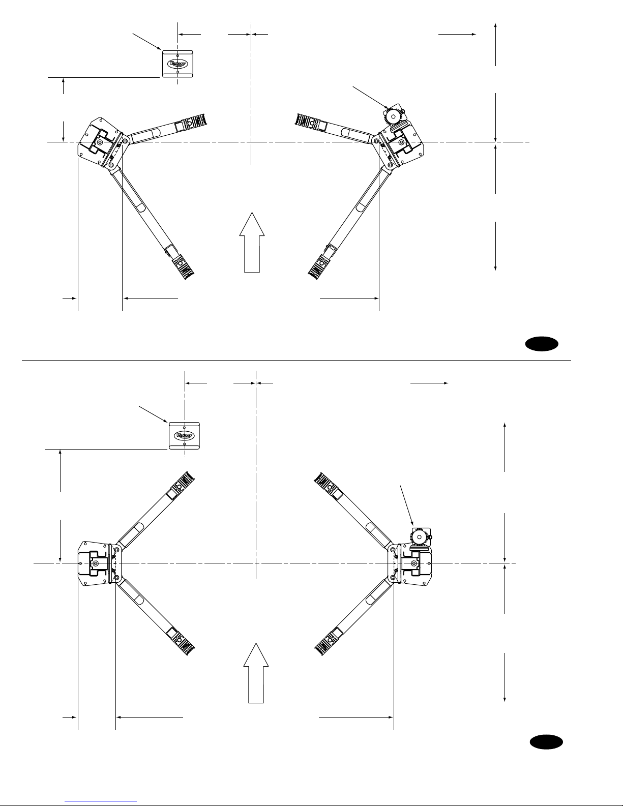
Wheel Spotting Dish
2' 2"
(657mm)
2' 5"
(737mm)
6' 0" (1829mm) minimum to nearest
obstruction or bay. 7' 0" (2134mm)
minimum to nearest wall.
Power Unit
(Passenger Side)
APPROACH
9' 0" (2743mm) minimum
to nearest obstruction
15' 0" (4572mm) minimum
to nearest obstruction
18"
(457mm)
*NOTE: Dimension is from Inside of Baseplate to Inside of Baseplate.
Wheel Spotting Dish
3' 10"
(1178mm)
7' 11-3/8" (2423mm) SPOA7*
7' 3-3/8" (2219mm) SPOA7NB (Narrow Bay)*
8' 5-3/8" (2575mm) SPOA9*
2' 5"
(737mm)
6' 0" (1829mm) minimum to
nearest obstruction or bay.
7' 0" (2134mm) minimum to
nearest wall.
Power Unit
(Passenger Side)
Fig. 1a
11' 0" (3353mm)
minimum to nearest
obstruction
15"
8' 11-5/8" (2734mm) SPO9*
(381mm)
*NOTE: Dimension is from Inside of Baseplate to Inside of Baseplate.
13' 0" (3963mm)
minimum to nearest
obstruction
APPROACH
Fig. 1b
2

1. Lift Location: Use architects plan when
available to locate lift. Fig. 1a & Fig. 1b shows
dimensions of a typical bay layout.
2-1/4"
2. Lift Height: See Fig. 4 for overall lift height of
each specific lift model. Add 1 min. to overall
height to lowest obstruction.
WARNING
DO NOT install this lift in a pit
or depression due to fire or explosion risks.
3. Column Extensions: Before standing columns
upright, install the column extensions using (12)
3/8-16NC x 1/2 Flanged HHCS, Fig. 4.
4. Latch Cable Guides: Install the latch cable
guides to column extensions with (4) 1/4-20NC x
1 HHCS and 1/4-20NC Flanged Locknuts, Fig. 1c,
Fig. 1d, & Fig. 10b.
NOTE: Latch cable guide must be toward approach
side of the column extension. Coat the cable contact
surface with a light grease such as TUFOIL.
SPOA7/SPOA9
Column
Extension
4-1/4"
Drill holes using
3/4" carbide
tipped masonary
drill bit per ANSI
standard
B94.12.1977
Clean hole.
Run nut down just
below impact section
of bolt. Drive anchor
into hole until nut and
washer contact base.
4-1/4"
Tighten nut with
Torque wrench to
150 ft.-lbs.
3-1/4"
Fig. 2
Installation torque of 150 ft-lbs. is required for all anchor bolts.
NOTE: Use
rectangular shims at
inside edge of
baseplate. Use
constructions
adhesive or silicon
cement to hold shim
in place. INSURE
shims are held tightly
between base plate
and floor after
torquing anchors.
Anchor
Shims
(1/2" Max.)
Fig. 3
Nut
Flat
Washer
NOTE: If more than 2 horse shoe shims are used at any of the column
anchor bolts, pack non-shrink grout under the unsupported area of the
column base. Insure shims are held tightly between the baseplate and
floor after torquing anchors.
Overhead Assembly
1/4"-20NC x 1"
HHCS & 1/4"
Flanged Locknut
Latch Cable
Guide
Latch Cable
Guide
1/4"-20NC x 1"
HHCS & 1/4"
Flanged Locknut
SPO9
Extension
Column
APPROACH
APPROACH
Fig. 1c
Fig. 1d
3/8"-16NCx1" HHCS
& Flanged Locknut
12' 0" (3658mm)
Top of Cylinder
11' 8" (3556mm)
Top of Overhead
Assembly(std.)
11' 4" (3454mm)
Top of Overhead
Assembly
(Low Ceiling)
All above for
both SPOA7
and SPOA9
(Low Ceiling is
N/A for SPO9)
(2)3/8" Star Lockwashers
on right side only
Use (4) 3/8"-16NCx1/2"
Flanged HHCS in front
and (2) in the back
Use (1) 3/8" Star
Lockwasher on right extension
Fig. 4
IMPORTANT: All star washers are to be mounted on the right
side column to ensure grounding of overhead limit switch. Star
washers are not needed when mounting to left side column.
Notice the column extension mounting, Fig. 4 and overhead limit
switch mounting as well in Fig. 6.
3
5. Lift Setting: Position columns in bay using
dimensions shown in Fig. 1a & Fig. 1b. Place column
with power unit mounting bracket on vehicle passenger
side of lift. Both column base plate backs must be square
on center line of lift. Notches are cut into each base plate
to indicate center line of lift.
Use appropriate equipment to raise carriage to first latch
position. Be sure locking latch is securely engaged.
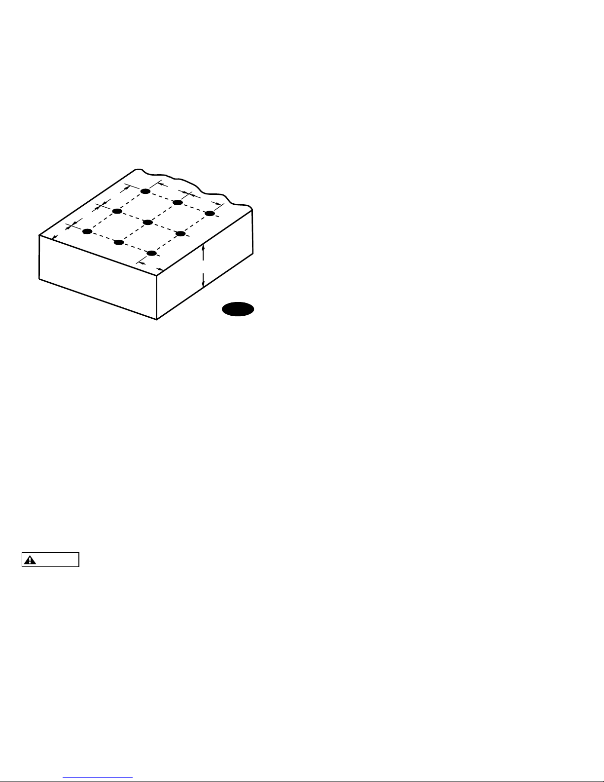
C
C
B
C
C
B
A
Fig. 5
A) Concrete Thickness &
Hole Depth 4-1/4" (108mm)
B) Edge Distance 4-3/4" (121mm)
C) Hole Spacing 6-1/2" (165mm)
If anchors do not tighten to 150 ft-lbs. installation torque,
replace concrete under each column base with a 4' x 4' x
6" thick 3000 PSI minimum concrete pad keyed under and
flush with the top of existing floor. Let concrete cure
before installing lifts and anchors.
7a. Overhead Assembly: Fig. 6: Adjust overhead to
appropriate dimension. Install (4) 3/8"-16NC x 3/4"
HHCS & 3/8-16NC Flanged Locknuts, do not tighten.
Mount switch assembly towards power unit column as
shown, using (2) 1/4"-20NC x 3/4" lg. HHCS, 1/4-20NC
Nuts and 1/4" Star Washers. For Narrow Bay installation,
see step 7b, all others go to step 7c.
7b. For Narrow Bay installation only: Cut off 11 from
the length of the bar and cushion on the end opposite the
1/4 mounting hole. Continue to step 7c.
7c. Continued Overhead Assembly: Insert 1/4"-20NC
x 2" HHCS through pivot hole in end of switch bar. Insert
opposite end of bar through slot in switch mounting
bracket. Then secure HHCS and Switch Bar to overhead
as shown, using 3/4" spacer and 1/4-20NC Locknut.
Tighten Hex bolt leaving 1/16 gap between the spacer
and the overhead assembly.
8. Overhead Installation: Install overhead assembly to
column extensions with (2) star washers and (8) 3/8" x 1"
HHCS and 3/8 Flanged Locknuts, Fig. 4. Tighten bolts
at center of overhead assembly.
Concrete and Anchoring: Concrete shall have a
compression strength of at least 3,000 PSI and a minimum
thickness of 4-1/4" in order to achieve a minimum anchor
embedment of 3-1/4". When using the standard supplied
3/4 x 5-1/2 lg. anchors, if the top of the anchor exceeds
2-1/4 above the floor grade, you DO NOT have enough
embedment.
Drill (10) 3/4" dia. holes in concrete floor using holes in
column base plate as a guide. See Fig. 2 and Fig. 5 for
hole depth, hole spacing, and edge distance requirements.
CAUTION
DO NOT install on asphalt or other
similar unstable surfaces. Columns are
supported only by anchors in floor.
6. IMPORTANT: Using the horse shoe shims
provided, shim each column base until each column is
plumb. If one column has to be elevated to match the
plane of the other column, full size base shim plates
should be used (Reference FA5112 Shim Kit). Recheck
columns for plumb. Tighten anchor bolts to an
installation torque of 150 ft-lbs. Shim thickness MUST
NOT exceed 1/2 when using the 5-1/2 long anchors
provided with the lift. Adjust the column extensions
plumb.
9. Power Unit: First install (1) star washer onto one of
the (4) 5/16"-18NC x 1-1/2" HHCS. This is very
important for grounding. Put the (4) 5/16"-18NC x 1-1/2"
HHCS thru holes in power unit bracket using Push-Nuts
to hold in place, Fig. 7a & Fig. 7b. Mount unit with motor
up to column bracket and install (4) 5/16 star washers
and 5/16 Nuts. Install and hand tighten Branch Tee to
pump until O-ring is seated. Then tighten locknut to 35-40
ft-lbs, and connect supply hoses to Tee, Fig. 8a or Fig. 8b.
NOTE: Over tightening locknut may tear O-ring.
4

3/8"-16NC x 3/4" HHCS
& Flanged Locknut
SPOA9
7-3/4"
Spacer
Spacer
1/4"-20NC x 2" HHCS
& 1/4" Locknut
3/8"-16NC x 3/4" HHCS
& Flanged Locknut
1/4"-20NC x 2" HHCS
& 1/4" Locknut
1/4"-20NC x 3/4" HHCS, Star Lockwasher, and Nut
111-3/8"
SPO9
1/4"-20NC x 3/4" HHCS, Star Lockwasher, and Nut
114"
11-3/4"
Spacer
Spacer
3/8"-16NC x 3/4" HHCS
& Flanged Locknut
1/4"-20NC x 2" HHCS
& 1/4" Locknut
1/4"-20NC x 3/4" HHCS, Star Lockwasher, and Nut
3/8"-16NC x 3/4" HHCS
& Flanged Locknut
1/4"-20NC x 2" HHCS & 1/4" Locknut
1/4"-20NC x 3/4" HHCS, Star Lockwasher, and Nut
105-3/8"
97-3/8"
SPOA7
SPOA7 Narrow Bay
7-3/4"
7-3/4"
Fig. 6
5
 Loading...