

Rotary SPO12 Standard, SPO12 Hummer, SPO12 Sprinter Installation Instructions Manual
I
N
N
S
S
I
SPO12
Standard/Hummer/Sprinter
Two Post Surface Mounted Swing Arm Frame Engaging Lift
Standard (500/700 Series) Capacity: 12,000 lbs.
Hummer (5W0/7W0 Series) Capacity: 12,000 lbs.
Sprinter (5A0/7A0 Series) Capacity: 9,000 lbs.
Español Página 25
Le Français La page 49
T
T
A
A
L
L
L
L
A
A
T
T
I
O
O
N
N
I
OPERATING CONDITIONS
Lift is not intended for outdoor use
and has an operating ambient temperature
range of
41°-104°F (5°-40°C)
IMPORTANT
Installation and Service of Automotive Lifts
before installing lift.
Reference ANSI/ALI ALIS,
Safety Requirements for
I
N
N
S
S
T
T
R
R
U
U
C
C
T
T
I
O
O
N
N
I
I
© May 2019 by Vehicle Service Group. All rights reserved. CO10473
IN20272
Rev. AC 5/22/2019
S
S
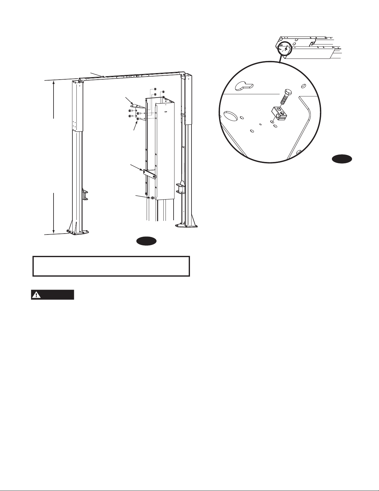
INSTALLATION INSTRUCTIONS
8-1/2" LOWER HEIGHT
SETTING
STANDARD HEIGHT
SETTING
4" LOWER HEIGHT
SETTING
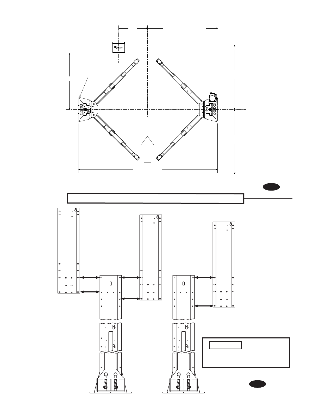
(14) 3/4” Anchors
56”
Left Rear
2’-5”
11’-5 5/8” SPO12
6’-0” minimum to nearest
obstruction or bay. 7’-0”
minimum to nearest wall.
Right Front
13’ minimum to
nearest obstruction
13’ minimum to
nearest obstruction
APPROACH
SPO12 Standard (500 Series) & SPO12 Sprinter (5A0 Series)
SPO12 Standard (700 Series) & SPO12 Sprinter (7A0 Series)
Note: See Pg. 3 for Hummer (5W0/7W0 Series) Lifts.
Fig. 1a
ATTENTION
: Continue to
page 7 for SPO12 standard
installation.
Fig. 1b
2
SPO12 Hummer Supplement Instructions
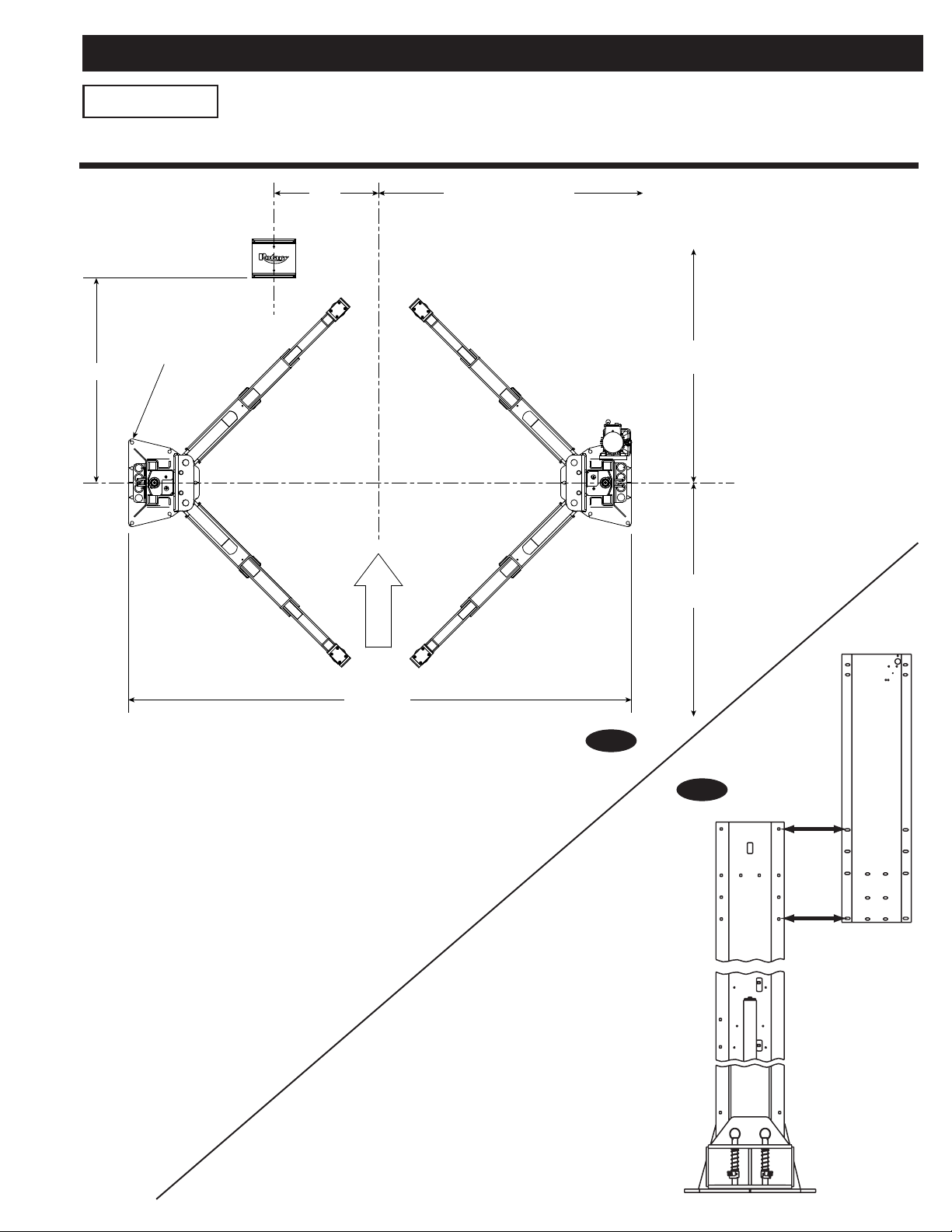
IMPORTANT
If you have ordered a SPO12 Hummer Lift (5W0/7W0 Series) these figures
MUST be used in place of the standard instruction figures on page 2.
56”
(14) 3/4” Anchors
Left Rear
2’-5”
7’-0” minimum to nearest
obstruction or bay. 8’-0”
minimum to nearest wall.
Right Front
13’ minimum to
nearest obstruction
13’ minimum to
nearest obstruction
APPROACH
12’-10 5/8”
SPO12 Hummer Lift (5W0 Series)
SPO12 Hummer Lift (7W0 Series)
Fig. 1a
Fig. 1b
3
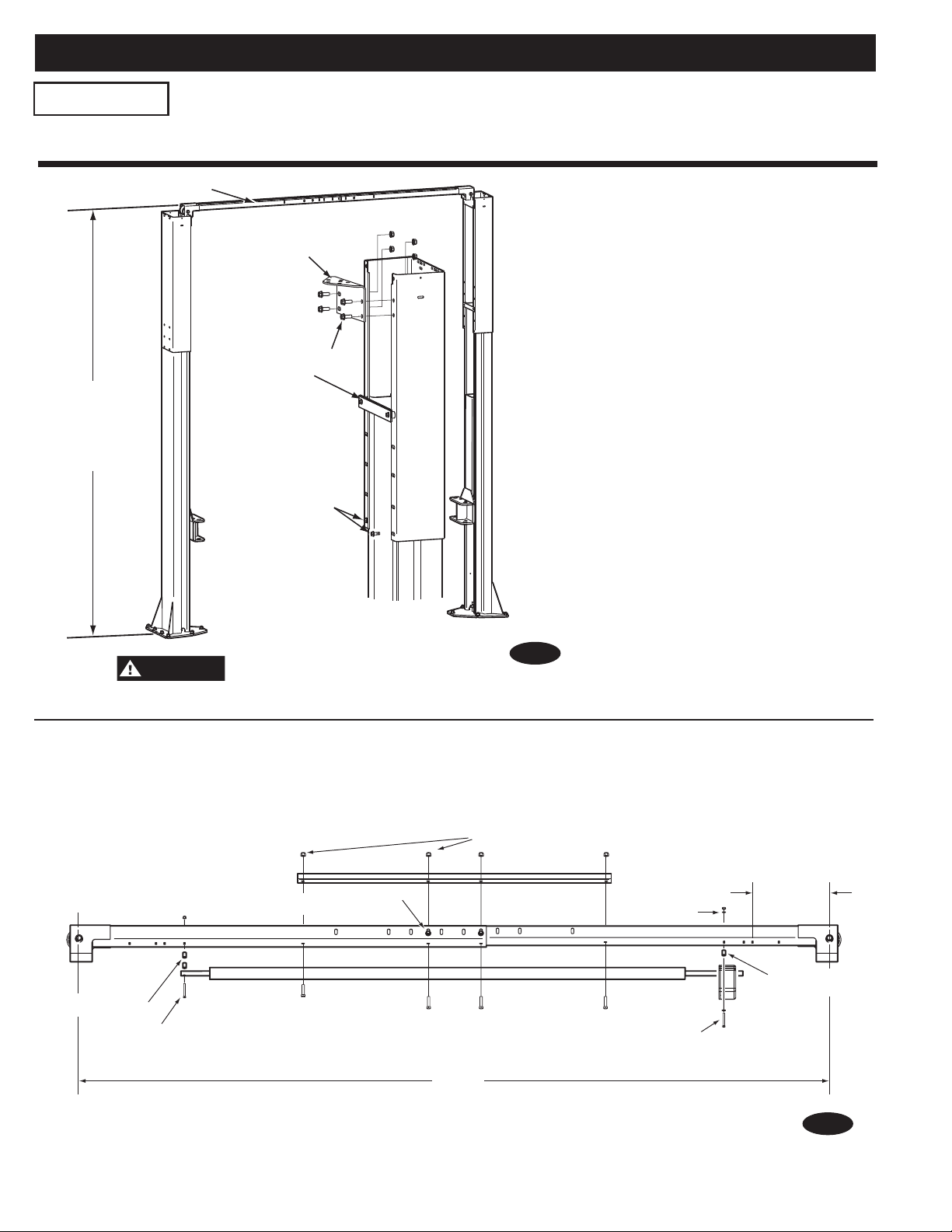
Overhead Assembly
13'-11 1/2"
To p
Overhead
Assembly
(14'-11 1/2" EH1)
Tie Bar & Spacers -use
(2)3/8"-16NCx 2-1/2"
Carriage Bolts
And Flanged Lock Nuts
Use (2) 3/8"-16NCx1"
Carriage Bolts
In Front And
(2) In the Back
3/8"-16NCx3/4" HHCS
& Flanged Locknut
Mounting
Bracket
SPO12 Hummer Supplement Instructions
WARNING
IMPORTANT
131"
11-3/4"
(2)3/8"-16NC x 3/4" HHCS & Flanged Locknut
(4)3/8"-16NC x 1" Flanged HHCS and Flanged Nuts
1 Phase Lifts
1/4"-20NC x 2-3/4" HHCS
& 1/4" Locknut
1/4"-20NC x 2-3/4" HHCS,
Flat Washer, Spacer, and Nut
Spacer
Star
Washer
This Side
2 Spacers
If you have ordered a SPO12 Hummer Lift (5W0/7W0 Series) these figures MUST
be used in place of the standard instruction figures on pages 7 & 8.
DO NOT install this lift in a pit or
depression due to fire or explosion risks.
Fig. 2
Fig. 6
4
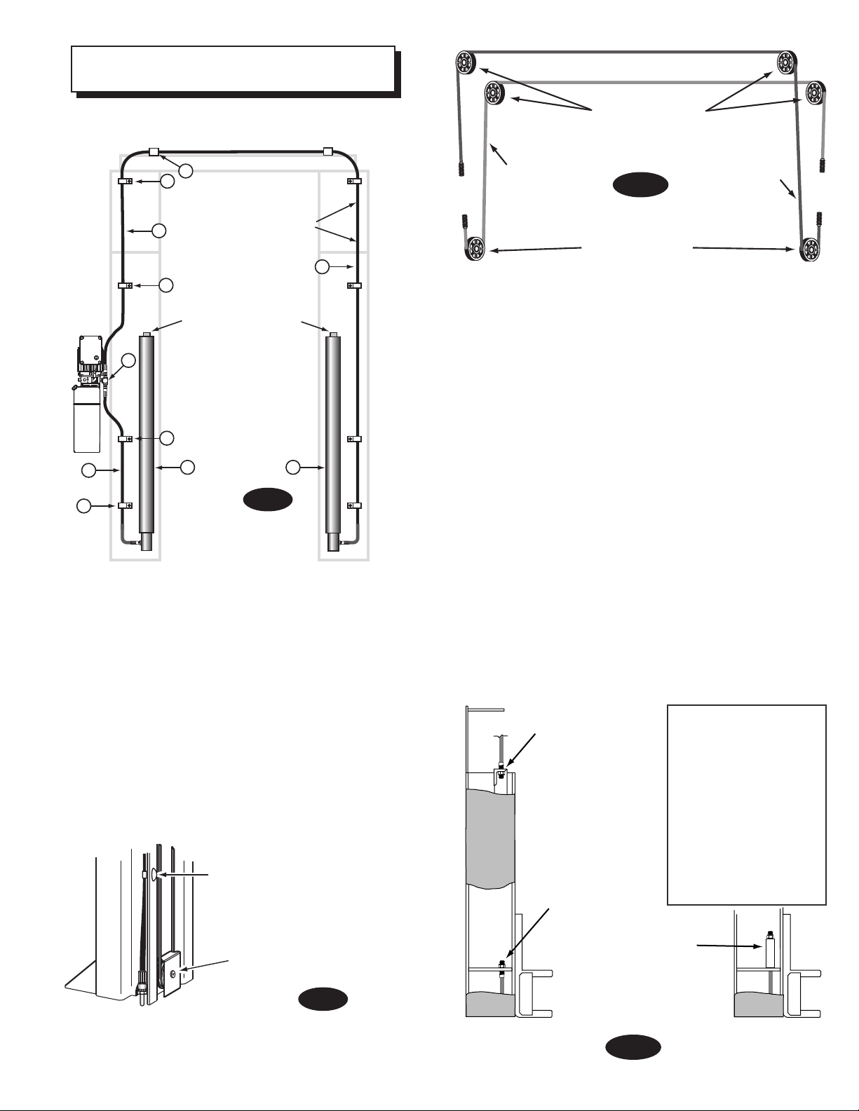
1. Lift Location: Use architects plan when available
WARNING
to locate lift. Fig. 1a shows dimensions of a typical bay
layout.
Lift Height: See Fig. 2 for overall lift height of each
specific lift model. Add 1” min. to overall height to
lowest obstruction.
Overhead Assembly
Mounting
Bracket
SPO12 (500/700) &
SPO12 (5A0/7A0)
13'-8"
[4166mm]
STD. Top
Overhead
Assembly
EH-1 14’-8” [4470mm]
EH-2 15’-8“ [4775mm]
EH-3 16’-8” [5080mm]
(SPO12LC
11’-8”
[3556mm])
3/8"-16NCx3/4" HHCS
& Flanged Locknut
Tie Bar & Spacers -use
(2) 3/8"-16NCx2-1/2"
Carriage Bolts and
Flanged Locknuts
Use (2) 3/8"-16NCx1"
Carriage Bolts and
Flanged Locknuts in
front and (2) in the back
Fig. 2
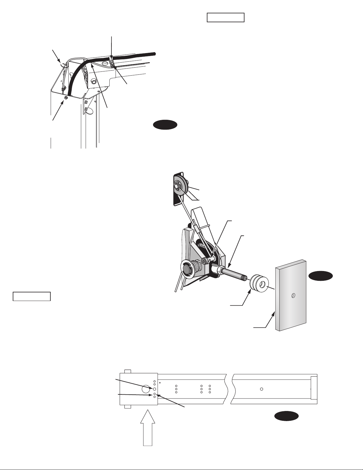
Overhead Mounting Bracket: Install Mounting Brackets
to column extensions as shown, Fig. 2.
Fig. 3
3. Column Extensions: While column is on the ground,
install column extensions using (4) 3/8”-16NC x 1” lg.
Carriage Bolt and Flanged Locknut, Fig. 3 & Fig. 1b. Use (2)
3/8”-16NC x 2-1/2” lg. Carriage Bolt and Flanged Locknut to
attach the tie bar and the column extension together at the
column’s uppermost holes, Fig. 3. The tie bar is positioned
on the outside of the column extension. Adjust the column
extensions plumb.
Note: See Pg. 3 for Hummer (5W0/7W0 Series) Lifts.
DO NOT install this lift in a pit or
depression due to fire or explosion risks.
2. Latch Cable Guides: Install the latch cable conduit guide
brackets to column extensions with (1) 1/4”-20NC x 1” HHCS
and 1/4”-20NC Flanged Locknuts, Fig. 3. HHCS should go
through hole nearest the edge as shown, Fig. 3.
4. Lift Setting: Position columns in bay using dimensions
shown in Fig. 1a. Place column with power unit mounting
bracket on vehicle passenger side of lift. Both column base
plate backs must be square on center line of lift. Notches
are cut into each base plate to indicate center line of lift.
Use appropriate equipment to raise carriage to first latch
position. Be sure locking latch is securely engaged.
IMPORTANT: All star washers are to be mounted on the
right side column to ensure grounding of overhead limit
switch. Star washers are not needed when mounting to left
side column. Notice the column extension mounting, Fig. 3
and overhead limit switch mounting as well in Fig. 3 & Fig. 6.
5

5. Concrete and Anchoring:
IMPORTANT
CAUTION
Reference IN20294 if Sprinter long arms
are going to be used for this installation or if the lift will
possibly be retro-fit with them in the future. Different
concrete and anchoring requirements are required.
Drill (14) 3/4” dia. holes in concrete floor using holes in
column base plate as a guide. See Figs. 4 and 5 for hole
requirements.
DO NOT install on asphalt or other similar
unstable surfaces. Columns are supported only by
anchors in floor.
IMPORTANT: Using the horse shoe shims provided,
shim each column base until each column is plumb. If
one column has to be elevated to match the plane of
the other column, full size base shim plates should be
used (Reference Shim Kit). Recheck columns for plumb.
Tighten anchor bolts to an installation torque of 110 ft-lbs.
Shim thickness MUST NOT exceed 1/2” when using the
5-1/2” long anchors provided with the lift.
If anchors do not tighten to 110 ft-lbs. installation torque,
replace concrete under each column base with a 4’ x 4’
x 6” thick 3000 PSI minimum concrete pad keyed under
and flush with the top of existing floor. Let concrete cure
before installing lifts and anchor.
6
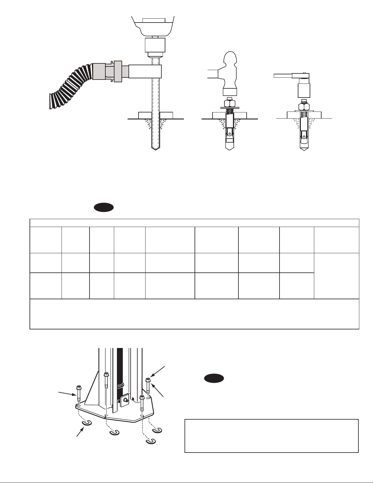
Fig. 4
Shims (1/2"(12.7mm) Max.)
Nut
Flat Washer
Anchor
Anchor: Min
Concrete
Thickness
Hilti Kwik
Bolt III (3/4" x
5-1/2")
Hilti HY200
(with HAS
threaded rod)
4-1/4"
(108mm)
5-1/4"
(134mm)
Min Edge
Distance
3-3/8"
(86mm)
1-3/4"
(45mm)
*The supplied concrete fasteners meet the criteria of the American National Standard
“Automotive Lifts - Safety Requirements for Construction, Testing, and Validation” ANSI/ALI ALCTV-2011,
and the lift owner is responsible for all charges related to any additional anchoring requirements as
specified by local codes. Contact customer service for further information at: 800.640.5438
Drill holes using 3/4” carbide
tipped masonry drill bit per
ANSI B212.15-1994 (R2000).
Construction dust collected
Run nut down just below impact
section of bolt. Drive anchor
into hole until nut and washer
contact base.
Tighten nut with Torque
wrench to 110 ft.-lbs.
(149 Nm).
per OSHA 29 CFR 1926.1153.
12K 2-Post Lift Anchor Installation Reference Guide
Min Anchor
Embedment
3-1/4" (83mm) 110 3000 4'x4'x6" 65 Varies by
3-1/2" (89mm) 100 / less than 3-3/4"
Installation Anchor
Torque Ft-lbs
edge distance use
Torque Value of 30
FT/LBS
Min Concrete PSI
Strength - For All
Standards
3000 4'x4'x6" N/A
Concrete pad
Size If Concrete
Does Not Meet
Requirements
Maintenance
Torque
Values
SEISMIC
location consult
with your
structural engineer
and manufacturer’s
representative.
Fig. 5
NOTE: If more than 2 horse shoe shims are used at any of the
column anchor bolts, pack non-shrink grout under the unsupported
area of the column base. Insure shims are held tightly between the
baseplate and floor after torquing anchors.
7
Hardware Detail For Overhead Assembly
1/4"-20NC x 2-3/4" HHCS
2 Spacers
Spacer
1/4" Lock Nut
Open Bar Side
HOLE
DETAIL
SPO12
1/4"-20NC x 2-3/4" HHCS
1/4" Lock Nut
1/4" Star Lock
Washer
1/4" Flat
Washer
Switch Box Side
(2)3/8"-16NC x 3/4" HHCS & Flanged Locknut
1/4"-20NC x 2-3/4" HHCS & 1/4" Locknut
114"
11-3/4"
(2)Spacers
(4)3/8"-16NC x 1" Flanged HHCS and Flanged Nuts
1 & 3 Phase Lifts
1/4"-20NC x 2-3/4" HHCS, Flat Washer, and Nut
Spacer
Star
Washer
This Side
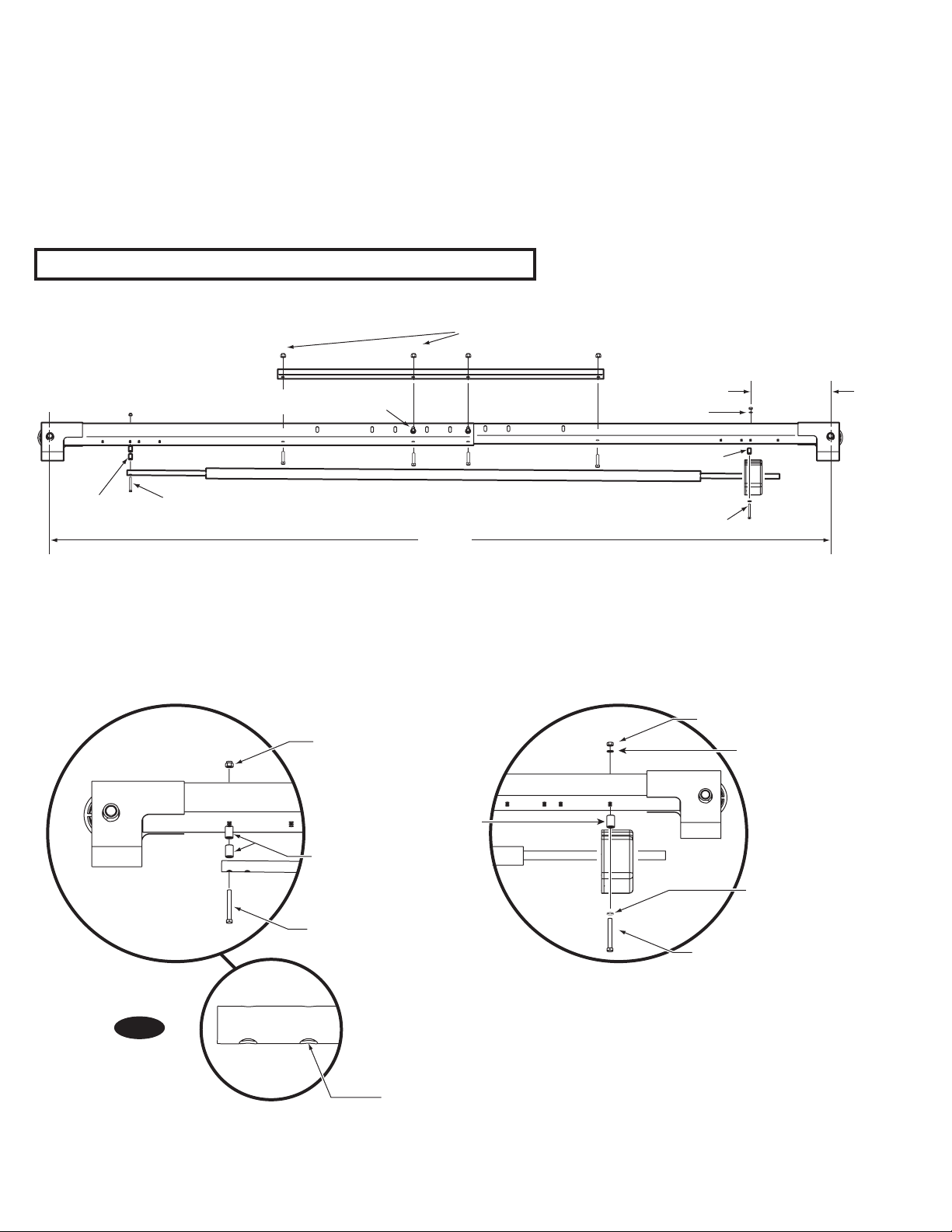
6. Overhead Assembly: Adjust overhead to 114”
between centerline of sheave pins, Fig. 6. Install (4)
3/8”-16NC x 2-3/4” Flanged HHCS & Flanged Locknuts, do
not tighten. Install overhead stiffener angle inside center
of overhead using (4) 3/8”-16NC x 1” Flanged HHCS and
Flanged Locknuts, see Fig. 6. Slide switch box over switch
bar ensuring lockout holes face the power unit column.
Use (2) 1/4”-20NC x 2-3/4” lg. HHCS, (2) flat washers, (2)
3/4” spacers, and (2) 1/4” star washers and nuts to mount
switch box to overhead, Fig. 7a and Fig. 7b.
Note: For Fig. 6, see Pg. 4 for Hummer (5W0/7W0 Series) Lifts.
7. For single phase and three phase lifts with push
button control box: Insert (2) 1/4”-20NC x 2-3/4” HHCS
through pivot hole in end of switch bar. Insert opposite
end of bar through slot in switch mounting bracket. Then
add spacers between the limit switch box and the
overhead, Fig. 6, using (2) spacers and
1/4”-20NC Locknut. Tighten Hex bolt leaving 1/16” gap
between the spacer and the overhead assembly.
Fig. 6
8

Use 3/8"-16NC x 3/4"
Flanged HHCS and
Flanged Locknuts
CAUTION
IMPORTANT
CAUTION
8. Overhead: Install overhead assembly to Mounting
Bracket with (2) 3/8”-16NC x 3/4” Flanged HHCS, (2) 3/816NC flanged locknut, Fig. 7c. Ensure limit switch box is
mounted on power unit side. Tighten bolts at center of
overhead assembly.
9. Power Unit: Put the (4) 5/16”-18NC x 1-1/2” flanged
locking HHCS thru holes in power unit bracket using PushNuts to hold in place, Fig. 8a. Mount unit with motor up to
column bracket and install (2) 5/16” Flanged locking Nuts.
Install and hand tighten Branch Tee to pump until O-ring
is seated. Continue to tighten the locknut to 10-15 ft-lbs.,
or until the nut and washer bottom out against the pump
manifold. NOTE: You may still be able to rotate the Branch
Tee. This is acceptable unless there is seepage at the
O-ring. If so, slightly tighten the locknut.
Over tightening locknut may tear O-ring or
distort threads in pump manifold outlet.
Fig. 7a
10. Hoses: Clean adapters and hose. Inspect all threads
for damage and hose ends to be sure they are crimped,
Fig. 8b. Install hose and hose clamps, Fig. 9a & Fig. 9d.
Flared Fittings Tightening Procedure
1. Screw the fittings together finger tight. Then, using the
proper size wrench, rotate the fitting 2-1/2 hex flats.
Flare seat MUST NOT rotate when
tightening. Only the nut should turn.
2. Back the fitting off one full turn.
3. Again tighten the fittings finger tight; then using a
wrench, rotate the fitting 2-1/2 hex flats. This will
complete the tightening procedure and develop a
pressure tight seal.
Overtightening will damage fitting resulting
in fluid leakage.
Fig. 7b
COVER NOT SHOWN
Fig. 7c
9
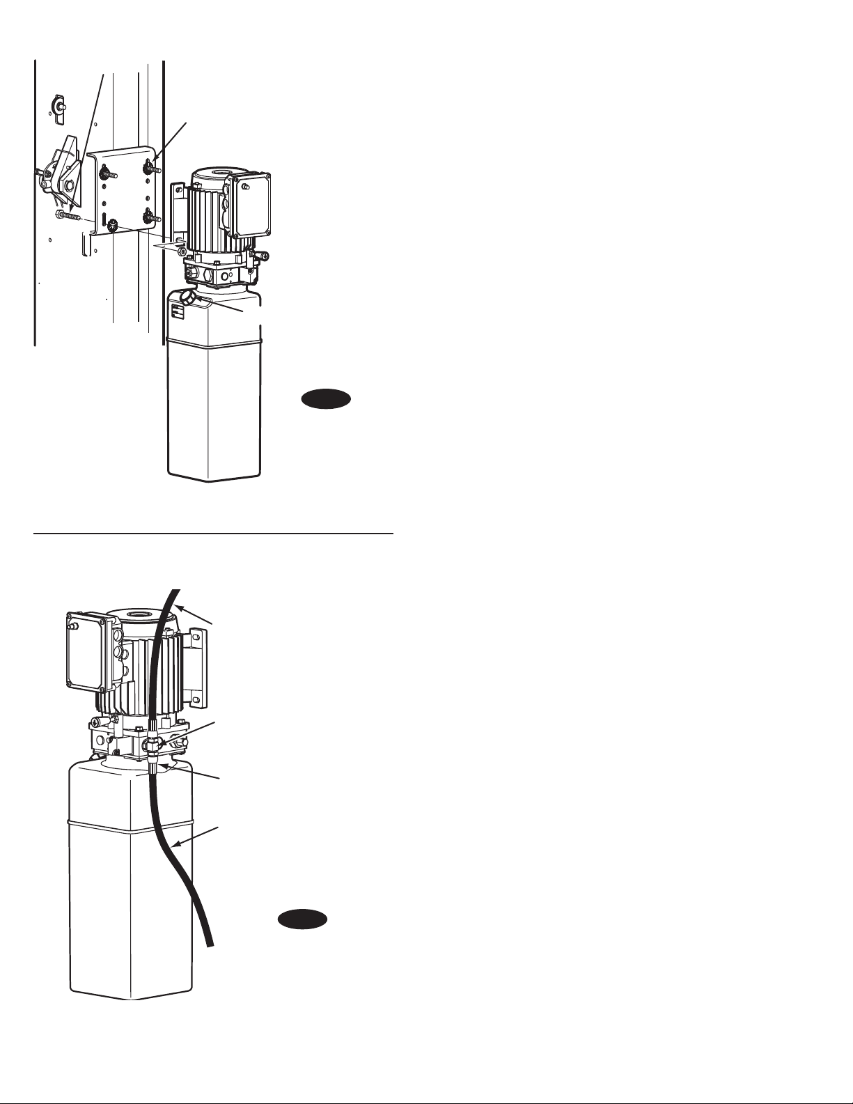
Push nuts hold bolts to brackets.
Fill Breather Cap
Use (4)5/16"-18NC
x1-1/2" lg. Flanged
Locking HHCS
and Nuts
Overhead
Hose
Power Unit
(Short) Hose
Crimped Hose
Sleeve (Typical)
Branch Tee
Fig. 8a
Adapter & Hose Installation (see Fig. 9a)
1. Install Pc. (2) with metal hose clamps, on power unit
column side connecting it to the cylinder (1) first.
2.
Install Pc. (3) with plastic hose clamps starting at
opposite column cylinder (1) and working toward the
power unit column. All excess hose should be at bends
& inside overhead assembly.
3. Install Pc. (4) into power unit.
4. Connect Pc. (2) & Pc. (3) to Tee (4).
NOTE: Route Power Unit hose inside columns using slots
provided at column base, Fig. 9b. Route Overhead Hose in
column channel on outside of column, Fig. 9b. Overhead
hose goes over top end of overhead assembly, Fig. 11a.
11. Equalizing Cables
A) Refer to Fig. 10a for the general cable arrangement.
First, run a cable end up through the small hole in the
lower tie-off plate. Fig. 10b.
B) Push the cable up until the stud is out of the carriage
top opening.
C) Run a nylon insert locknut onto the cable stud so 1/2”
(13mm) of the stud extends out of the locknut.
D) Pull the cable back down. Fig. 10b
E) Run cable around the lower sheave, then up and
around overhead sheave and across and down to the
opposite carriage. Fig. 10a.
F) Fasten the cable end to the carriage upper tie-off
bracket. Tighten the locknut enough to apply light
tension to the cable.
G) Repeat procedure for the second cable. Complete lift
assembly. Adjust the tension of both cables during the
final adjustments.
Fig. 8b
10
Attach hose to column
using 3/8"-16NC x 3/4"
Carriage Bolts, Flanged
Locknuts, and Hose Clips
Sheave Cover
1 1
2
6
4
6
FRONT
Hose runs down
approach side to
cylinder on left column.
Cylinder bleeders
Torque values
15 ft. lbs. Minimum
20 ft. lbs. Maximum
6
5
3
3
5
*
*
*
*
**
##
# #
NOTE: Overhead hose crosses and runs down
1st Cable
2nd Cable
Upper Sheaves
Lower Sheaves
approach side of left column to cylinder.
Fig. 10a
Fig. 9a
ITEM QTY. DESCRIPTION
1 2 Hydraulic Cylinder
2 1 Power Unit Hose
3 1 Overhead Hose
4 1 Branch Tee
5 2 Metal Hose Clips
6 8 Plastic Hose Clips
*6 3/8-16NC x 3/4” lg. Carriage Bolts
*6 3/8”-16NC Flanged Locknuts
#4 3/8-16NC x 3/4” lg. Flanged HHCS
#4 3/8”-16NC Flanged Locknuts
Upper Cable Tie Off
& 5/8" Nylon Insert
Locknut
Lower Cable Tie Off
& 5/8" Nylon Insert
Locknut
To set up cables for a low
ceiling(LC), use 3/4" SCH
80 steel pipe spacers (not
included) at the lower
cable tie off. The lengths
required are as follows:
4" Lower Height = 8"
(203mm) long pipe
8-1/2" Lower Height = 17"
(432mm) long pipe
3/4"(19mm)
SCHEDULE 80
Fig. 9b
11
steel pipe spacer
for Low Ceiling
Fig. 10b
IMPORTANT
Latch cable runs
along approach
side of overhead
Cable Guide
runs UNDER
hydraulic hose
Attach to extension using
wire tie. Use hole closest
to OUTSIDE edge and on
NON-APPROACH side.
1/4"-20NC x 1" HHCS
and Flanged Locknut
3/8"-16NC x 3/4" HHCS
and Flanged Locknut
3/8"-16NC x 3/4" HHCS
and Flanged Locknut
APPROACH
Attach Hose Clamps Here
Attach Latch Cable Conduit
Guide Bracket Here. Always
use two holes on approach
side of extension to attach bracket.
Always put HHCS through hole
closest to center of overhead.
IMPORTANT
Fig. 11a
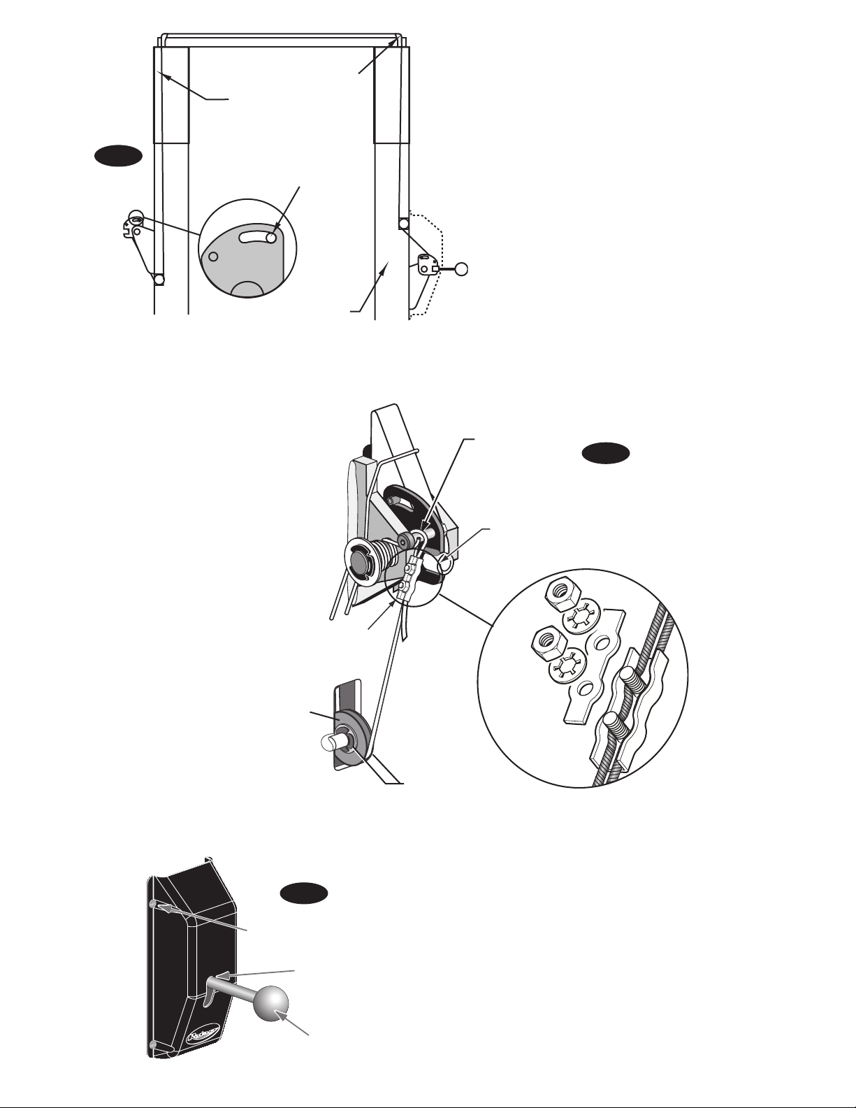
12. Locking Latch Cable
A) Install latch cable sheave and retaining rings in upper
slot of power unit column as shown, Fig. 11c.
B) Slip loop end of cable over end of shoulder screw on
right side latch control plate, Fig. 11c.
C) Feed the other end of the cable through the latch cable
sheave slot making sure that the cable is running
under the bottom side of the latch cable sheave and
inside the right column, Fig. 11c.
D) Attach latch cable conduit guide brackets to overhead
as shown, Fig. 11a & Fig. 11b. Always use the holes on
the approach side of the lift. HHCS should be in hole
nearest the center of the overhead, Fig. 11b.
E) Route cable up inside column and through the latch
cable guide, Fig. 11a & Fig. 12.
Using wire ties provided, tie off
cable guide to column extension as shown,
Fig. 11a. Guide must be attached in hole
closest to the outside edge of the column on
the NON-APPROACH side.
G) Bring the cable down inside the left column
and feed the end of the cable through the
lower latch cable sheave slot so that the
cable is now back outside the column, Fig.
13.
H) Install latch cable sheave and retaining
rings in lower slot of non-power unit column
as shown, Fig. 13.
I) Route cable under the bottom side of the
latch cable sheave, Fig. 13.
J) At this point you MUST install the latch
handle, jam nut, and right column latch
cover Fig. 11c & Fig. 14. Install latch handle
ball, Fig. 14.
Latch Cable Sheave
(2) 3/8" Retaining Rings
Shoulder Bolt
Install Latch Handle using a 3/8"
hex jam nut to lock in place. Then
install flat washers and slot cover.
Fig. 11c
Using wire ties provided, tie off cable guide
to column extension as shown, Fig. 11a. Guide must
be attached in hole closest to the outside edge of the
column on the NON-APPROACH side.
F) Continue routing cable to the left column latch cable
guide, Fig. 11a & Fig. 12, routing the cable through the
left column latch cable guide, Fig. 11a.
(3) 3/8” Flat Washers
Slot Cover
Fig. 11b
12
Shoulder Bolt
Cable Clamp
Feed cable up through Cable
Clamp, loop over end of
shoulder bolt and feed back
down through Cable Clamp.
(2) 3/8" Retaining
Rings
Latch Cable Sheave
5/16-18NC x 3/8" lg. PHMS
Latch handle MUST be
positioned at the top of
the latch control cover.
Ball Handle
Fig. 12
Latch Cable Guide
Right Column
Latch Cable
Notice the clearance
removed between
Control Plate Slot
and Latch Dog Pin.
K) Insert cable in cable clamp along one side, loop
around shoulder screw and back down, inserting
cable along other side of cable clamp, Fig. 13. Place
top back on clamp, barely tightening.
L) Next, pull the control plate down, Fig. 12 & Fig. 13, to
eliminate any clearance between the control plate slot
and the latch dog pin, Fig. 12.
M) Using Pliers, pull cable tight and secure the clamp
close to the shoulder screw. Tighten clamp.
Fig. 13
Fig. 14
13
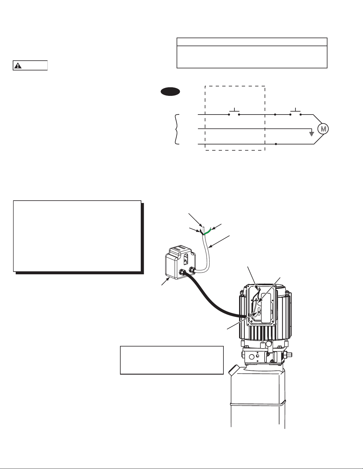
M
230V
60Hz
1 Ø
Black
Green
White
Overhead
Limit Switch
Up
Switch
White
Black
Black
Ov
Max.
Max.
Attach white
White
13. Electrical: Have a certified electrician run
CAUTION
NOTE: Assure cord used for connection
between the overhead switch and power
unit is of the type specified in:
UL201, Sections 10.1.1.3 & 10.1.1.4
(Example: SO, G, STO) Size for 25 amp
circuit. See UL 201, Section 15 for proper
wiring requirements for this connection.
appropriate power supply to motor, Fig. 15 & 16.
Size wire for 20 amp circuit. For single phase
4HP motor wire for 30 amp circuit. See Motor
Operating Data Table.
Never operate the motor on line
voltage less than 208V. Motor damage may occur.
Single Phase Power Unit
MOTOR OPERATING DATA TABLE - SINGLE PHASE
LINE VOLTAGE RUNNING MOTOR VOLTAGE RANGE
208-230V 50Hz. 197-253V
208-230V 60Hz. 197-253V
IMPORTANT: Use separate circuit for each power
unit. Protect each circuit with time delay fuse or
circuit breaker. For single phase 208-230V, use 20
amp fuse. For single phase 4HP motor use 30 amp
fuse. Three phase 208-240V, use 20 amp fuse. For
three phase 400V and above, use 10 amp fuse. For
wiring see Fig. 15, Fig. 16, and Fig.16b. All wiring
must comply with NEC and all local electrical
codes.
Note: 60Hz. single phase motor CAN NOT be run
on 50Hz. line without a physical change in the
motor.
Fig. 15
Note: 60Hz. Single phase motor CAN NOT be run on 50Hz. line
without a physical change in the motor.
Black
Green
208-230V 60Hz
Single Phase
Attach black wire
to one motor wire.
wire to one
motor wire.
erhead Switch
Voltage: 277V
Current: 25A
Attach ground wire here.
Connect supply to wires in box as
per Fig. 16. Attach ground wire to
screws provided.
14
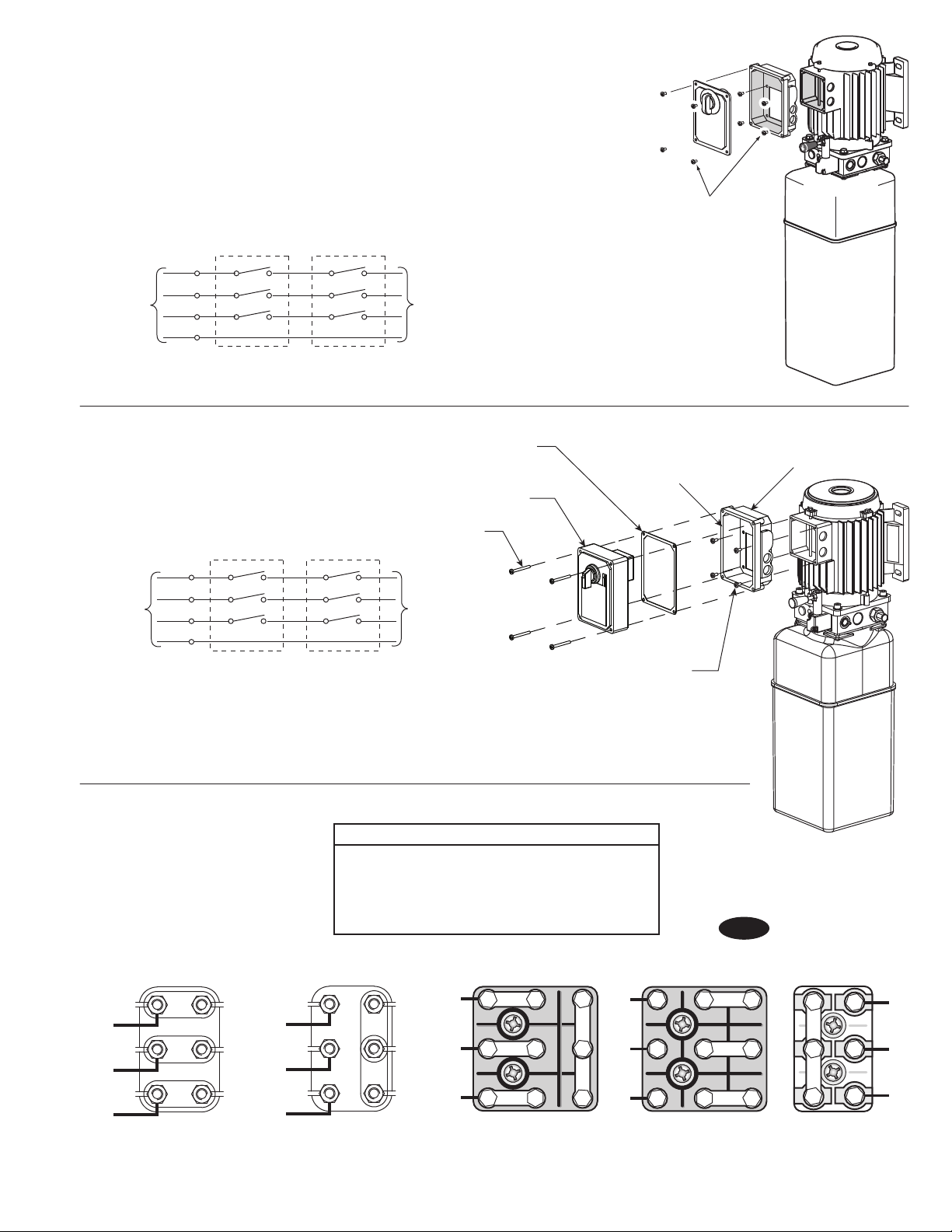
NOTE: Two Different Drum Switches were used
please select one of the two options below.
Newer model three phase lifts use the push button
control box with contactor. Its instructions follow
the Drum Switch instructions.
NOTES:
1. Unit not suitable for use in unusual conditions. Contact
Rotary for moisture and dust environment duty unit.
2. Control Box must be field mounted to power unit.
3. Motor rotation is counter clockwise from top of motor.
L1
3 Phase
Supply
L2
L3
1
2
3
4
5
6
1
2
5
6
7
8
MOTOR
PE
FOR 3 Ø POWER
UNITS: Attach Box using
M5 x 10 PHMS, Plated
Capacitor Box Attachment
Option One
3 Phase
Supply
OVERHEAD SWITCH
(WHERE APPLICABLE)
L1
1
2
3
L2
L3
4
5
6
PE
OVERHEAD SWITCH
(WHERE APPLICABLE)
DRUM
SWITCH
Gasket
Drum Switch
And Cover
(4) M5 x 45 PHMS, Plated
1
2
3
5
DRUM
SWITCH
4
6
MOTOR
(4) M5 x 10 PHMS, Plated
Capacitor Box To Power Unit
Capacitor Box Attachment
Option Two
Three Phase Power Unit
MOTOR OPERATING DATA TABLE - THREE PHASE
LINE VOLTAGE RUNNING MOTOR VOLTAGE RANGE
208-240V 50/60Hz. 197-253V
400V 50Hz. 360-440V
440-480V 50/60Hz. 396V-528V
575V 60Hz. 518V-632V
Re-seal Between
Box And Spacer
With Silicone
Sealer
Fig. 16
Capacitor
Box
L3
L2
L1
U1
V1
W1
50/60Hz. 3Ø
208-240V
Current Pin Layouts Older Pin Layouts
W2
U1
W2
T9
T3
L3
T6
L3
T3
L3
U2
V1
U2
T8
T2
L2
T5
L2
T2
L2
V2
W1
V2
L1
T7
T1
T4
L1
T1
L1
440-480V 50/60 Hz. 3Ø
380-400V 50 Hz. 3Ø
208-240V
50/60Hz. 3Ø
440-480V 50/60 Hz. 3Ø
380-400V 50 Hz. 3Ø
15
T9
T8
T7
T6
T5
T4
W2
V2
W1
T3
T2
V1
U2
U1
T1
575V 60 Hz. 3Ø
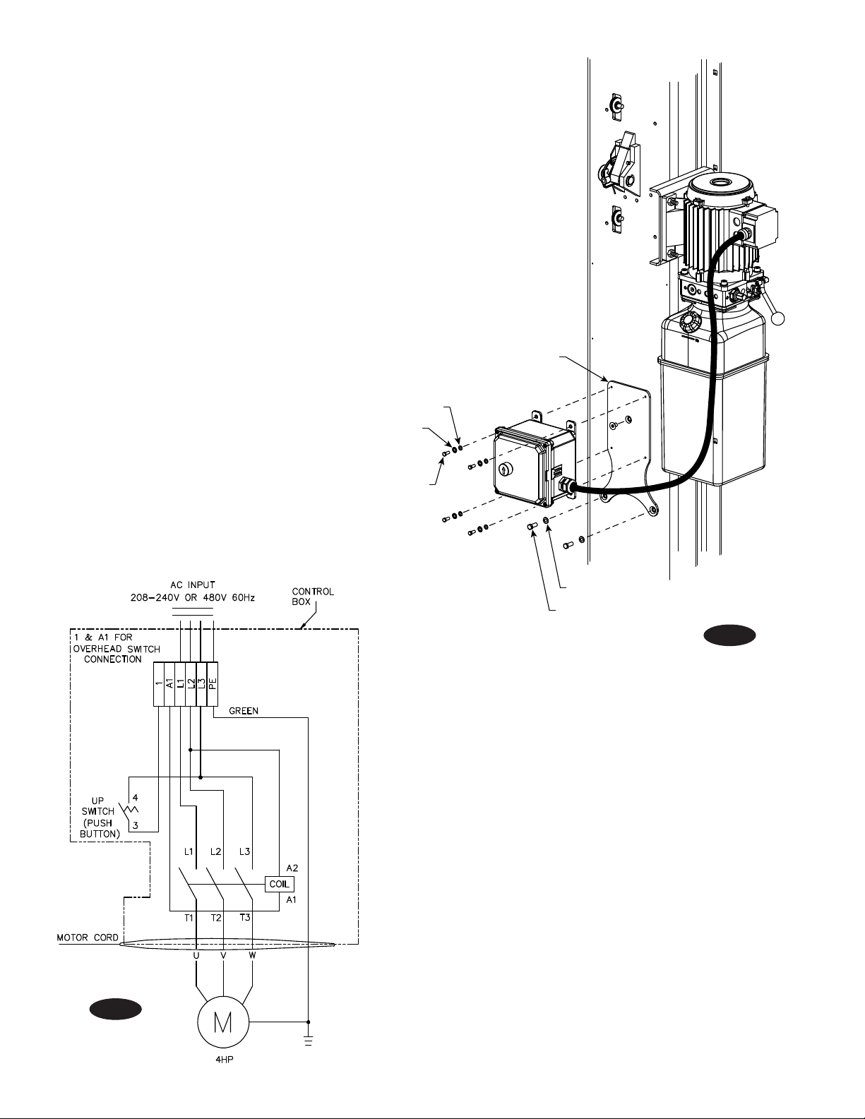
14. 3ø Control Box Installation:
Note:
The contactor in the control box has a 480V coil.
For installations where the electric supply is 230V,
the coil must be replaced with the extra 230V coil
shipped with the control box. For 575V electric
supply, the coil must be replaced with the extra
575V coil shipped with the lift.
A) Attach Mounting Bracket on column, as shown in Fig.
16a, using (1) 5/16”-18NC x 1/2” Socket Head Counter
Sunk Machine Screw, (2) 5/16”-18NC x 1/2” HHCS, and
(2) 5/16” Flat Washers.
B) Attach Control Box to Bracket using (4) 1/4”-20NC
x 1/2” HHCS, (4) 1/4” Flat Washers, and (4) 1/4” Star
Washers.
C) Route cord through strain relief on motor and connect
per table on the bottom of page 15.
1/4” Flat Washer
1/4” Star Washer
Mounting Bracket
1/4”-20NC x 1/2” HHCS
5/16” Flat Washer
5/16”-18NC x 1/2” HHCS
Fig. 16a
Fig. 16b
16
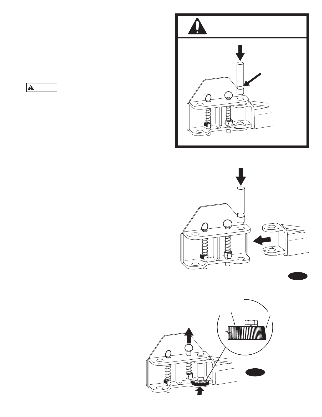
NOTE beveled
gear orientation
TOP
will be
marked on top side
of restraint gear
15. Oil Filling & Bleeding: Use Dexron III ATF, or
CAUTION
Installation
Pinch Point
Keep Hands
Above Groove
CAUTION
Hydraulic Fluid that meets ISO 32 specifications. Remove
fill-breather cap, Fig. 8a. Pour in (8) quarts of fluid.
Start unit, raise lift about 2 ft. Open cylinder bleeders
approximately 2 turns, Fig. 9a.
Close bleeders when fluid streams. Torque values for the
bleeders are 15 ft. lb. minimum and 20 ft lb. maximum.Fully
lower lift. Add more fluid until it reaches the
MIN_____ mark on the tank. Replace fill-breather cap.
If fill-breather cap is lost or broken, order
replacement. Reservoir must be vented.
16. Overhead switch: Check overhead switch assembly
to assure that switch bar is depressing switch plunger
sufficiently to actuate the switch. The overhead switch is
wired normally open, see Fig. 15, Fig. 16, and Fig. 16b. Lift
will not operate until weight of switch bar is depressing
switch plunger. Verify that Power Unit stops working when
switch bar is raised, and restarts when the bar is released.
17. Arms & Restraints: Before installing arms, raise
carriages to a convenient height. Grease swivel arm pins
and holes with Lithium grease. Slide arm into yoke, Fig.
17a. Install 1-3/4” diameter arm pin(s), Fig. 17a.
After installing arms and pins, install arm Restraint Gears
as follows: Install Restraint Gear onto arm clevis, as
shown, Fig. 17b. Ensure side of gear marked TOP is facing
upward, Fig. 17b.
NOTE: TOP is stamped on top side of gear. You may
need to pull up on the pin-ring to allow enough room to
install Restraint Gear.
Then, install the (2) 3/8”-16NC x 1-1/2” HHCS (8 total for
all 4 arms) and 3/8” Spring Lockwashers into the gear and
arm, but do not tighten. Reference Fig. 17c, Fig. 18, and Fig.
19.
Torque the Restraint Gear bolts to 30-34 ft.-lbs.
Fig. 17a
Fig. 17b
17

Use holes marked with arrow for Right Front
and Left Rear.
Use holes marked with arrow for Left Front
and Right Rear.
Fig. 17c
DO NOT use holes marked with arrows.
NOTE: To check operation of arm restraints, raise carriage
1” min. from full down position. Pull up on pin-ring and
adjust arms to desired position. To engage restraint, let
pin-ring down allowing gear teeth to mesh together. It may
be necessary to rotate arm slightly to engage gear teeth.
NOTE: Pin & Ring, Spring, & Gear Block are all
preassembled.
NOTE: Once arm is installed in yoke, pull up
actuator pin and swing arm fully around, being
sure that the Restraint Gear and Gear Block always
stay aligned. If they do not stay aligned, remove
restraint gear and install in the opposite position.
Fig. 18
Fig. 19
18
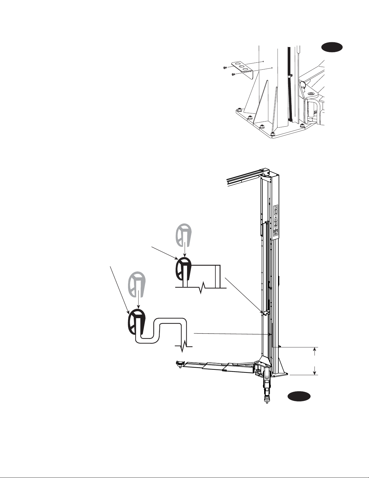
18. Installation of Rack for Adapter Extensions: Install
racks as shown, Fig. 20, using 5/16”-18NC x 3/8”
PHMS.
19. Door Bumper Installation:
1) Press long bumper on column edge, Fig. 21a.
2) Press short bumper on top edge of carriage
tube, Fig. 21a.
20. Latch Cable Adjustment:
A) Check to make sure the latch will properly engage and
disengage. Slowly release the latch handle. A 1/8”
gap between the top of the latch dog and the column
is allowable.
B) When raising, listen to latches to be sure that both
latch dogs fall into latch slots. If they do not, loosen
clamp and adjust tension as necessary.
C) Install left latch cover using 5/16-18NC x 3/8” lg PHMS.
21. Pressure Test: Run lift to full rise and keep motor
running for 5 seconds. Stop and check all hose
connections. Tighten or reseal if required. Repeat air
bleeding of cylinders.
Fig. 20
Padded section
of door bumper
faces out.
Short
Bumper
Long Bumper
21” (533mm)
Fig. 21a
19
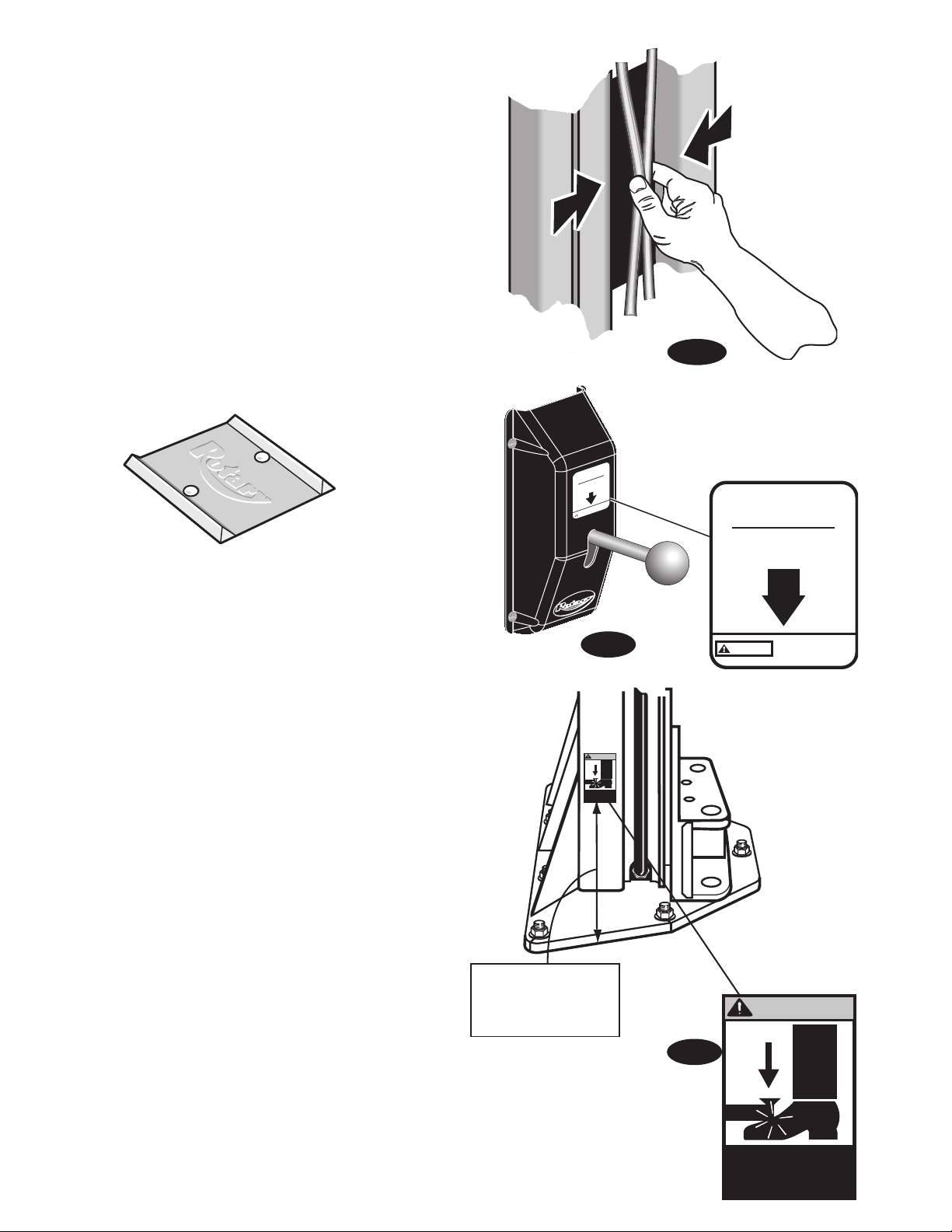
WARNING
Keep feet
clear of lift
while lowering
Place WARNING decal
a minimum of 8" from
the bottom of the decal
to the ground.
WARNING
Keep feet
clear of lift
while lowering
Raise Lift Off
Latches
Actuate To Release
Latches
Pinch Point
CAUTION
NP266 Rev C
Raise Lift Off
Latches
Actuate To Release
Latches
Pinch Point
CAUTION
NP266 Rev C
22. Equalizer Cable Adjustments: Raise lift to check
equalizer cable tension. Below carriage, grasp
adjacent cables between thumb and forefinger, with
about 15 lbs. effort you should just pull the cables
together. Adjust at upper tie-offs Fig. 21b.
23. Latch Release Decal: Install latch release decal on
cover above latch release handle, Fig. 22.
24. Pinch Point Decal Location: Install enclosed pinch
point decals. Place (1) decal on each column, Fig. 23.
25. Wheel Spotting Dish: Position wheel spotting dish as
illustrated in Fig. 1. Drill (2) 3/8” holes 2-1/2” deep in
concrete floor using holes in wheel spotting dish as
guide. Drive both anchors, provided, into concrete to
secure dish.
Fig. 21b
26. Upon completion of the assembly of the lift, the lift is
to be operated to assure proper function. Observe for
locks operating in all locking positions, each side lifts
equally, hydraulics do not leak, all electrical controls
function as labeled, all pneumatics are functional
and leak free, ramps rotate freely (if applicable), and
proper clearances with all items in bay have been
maintained.
Operate the lift with a typical vehicle and observe to
assure the same items for proper functioning.
Fig. 22
Fig. 23
20

NOTES
21

NOTES23NOTES
22
 Loading...