

Rotary SPM40 Operation & Maintenance Manual
O
P
E
SPM40
2-SÄULEN-HEBEBÜHNE
2 POST LIFT
SOLLEVATORE A 2 COLONNE
ELEVATEUR 2 COLONNES
ELEVADOR DE 2 COLUMNAS
R
A
T
I
O
N
&
M
A
I
N
T
E
N
A
N
C
E
M
A
N
U
A
L
© Gennaio 2007 by ROTARY Lift. Tutti i diritti riservati. CODICE
0446-M050-0
Rev. 0 (1/01/2017)

EG-Konformitätserklärung
EC Declaration of Conformity
im Sinne der EG-Richtlinie 2006/42/EG über Maschinen (Anhang II A)
according to EC directive 2006/42/EC on machinery (Annex II A)
Name und Anschrift des Herstellers Name und Anschrift seines in der EU
Name and address of the manufacturer: niedergelassenen Bevollmächtigten
his authorised representative in EU
Rotary Lift BlitzRotary GmbH
2700 Lanier Drive Hüfinger Str.55
Madison, IN, 47250 USA 78199 Bräunlingen, Germany
Diese Erklärung bezieht sich nur auf die Maschine in dem Zustand, in dem sie in Verkehr gebracht wurde; vom
Endnutzer nachträglich angebrachte Teile und/oder nachträglich vorgenommene Eingriffe bleiben unberücksichtigt. Die
Erklärung verliert ihre Gültigkeit, wenn das Produkt ohne Zustimmung umgebaut oder verändert wird.
This declaration relates exclusively to the machinery in the state in which it was placed on the market, and excludes
components which are added and/or operations carried out subsequently by the final user. The declaration is no more
valid, if the product is modified without agreement.
Hiermit erklären wir, dass die nachstehend beschriebene Maschine
Herewith we declare, that the machinery described below
Produktbezeichnung / product denomination: 2-Säulen-Hebebühne / 2-post vehicle lift
Serien- / Typenbezeichnung / model / type: SPOA3T
SPM 40
Tragfähigkeit 3500 kg / capacity 3500 kg
4000kg 4000kg
Maschinen-/Seriennummer / machinery / serial number: .........................
Baujahr / Year of manufacture: 20…
allen einschlägigen Bestimmungen der Maschinenrichtlinie 2006/42/EG entspricht.
Die Maschine entspricht zusätzlich den Bestimmungen der Richtlinien 2004/108/EG über elektromagnetische
Verträglichkeit und 2006/95/EG über elektrische Betriebsmittel
Maschinenrichtlinie 2006/42/EG eingehalten).
(Schutzziele wurden gemäß Anhang I, Nr. 1.5.1 der
is complying with all essential requirements of the Machinery Directive2006/42/EC.
In addition the partly completed machinery is in conformity with the EC Directives 2004/108/EC relating to
electromagnetic compatibility and 2006/95/EC relating to electrical equipment
accordance with Annex I No. 1.5.1 of the Machinery Directive 2006/42/EC).
(Protection objectives have been met in
Angewandte harmonisierte Normen / Harmonised Standards used
EN 1493: 2010 Fahrzeug-Hebebühnen / Vehicle lifts
EN ISO 12100:2010 Sicherheit von Maschinen - Grundbegriffe / Safety of Machinery- Basic concepts
EN 60204-1:2006+A1:2009 Elektrische Ausrüstung von Maschinen / Electrical equipment of machines
EN 349:1993+A1:2008 Sicherheit von Maschinen-Mindestabstände / Safety of machinery - Minimum gaps
EN ISO 13850:2008 Sicherheit von Maschinen-Not-Halt / Safety of machinery – Emergency stop
Angewandte sonstige technische Normen und Spezifikationen
Other technical standards and specifications used:
BGG 945 Prüfung von Hebebühnen / inspection of vehicle lifts
BGR 500 Betreiben von Arbeitsmitteln / management of working appliances
BGV A3 Unfallverhütungsvorschrift elektrische Anlagen und Betriebsmittel / law accident prevention regulation of
electric facilities and equipment
Bevollmächtigter für die Zusammenstellung der relevanten technischen Unterlagen:
The person authorised to compile the relevant technical documentation:
Herr Pohl; Hüfinger Str. 55; 78199 Bräunlingen
Ort / Place : Bräunlingen
Datum / Date : 19.03.2013
1/03/2017
______________________
Geschäftsführer / Managing Director
Frank Scherer
ACHTUNG!
- Diese Anleitung ist ergänzender Bestandteil des Produktes und muss zusammen mit der Hebebühne
sorgfältig aufbewahrt werden.
- Die Anleitung in einem bekannten und leicht zugänglichen Ort aufbewahren und bei Bedarf zu Rate
ziehen. Alle Bediener des Produktes müssen zwecks Einsichtnahme Zugang zur Anleitung haben. Alle
Schäden, die auf Nichtbeachtung der Anweisungen dieser Anleitung oder auf einen unsachgemässen
Betrieb der Hebebühne zurückzuführen sind, sind nicht dem Hersteller anzulasten und befreien die Firma
ROTARY von jeglicher Haftungspflicht.
CAUTION!
- This manual is an integral part of the product and must be kept together with the lift throughout its lifetime.
- It should therefore be kept in an easily accessible and familiar place and consulted when in doubt. All
product operators must be able to read the manual. Any damage resulting from improper use of the lift and
failure to follow the instructions contained in this manual will release ROTARY from any liability.
ATTENZIONE!
- Il presente manuale costituisce parte integrante del prodotto, dovrà seguire tutta la vita operativa del
sollevatore.
- Conservarlo, quindi, in luogo noto e facilmente accessibile e consultarlo ogni qualvolta sorgano dubbi.
Tutti gli operatori al prodotto devono poter leggere il manuale. Ogni danno derivante dalla mancata osservanza delle indicazioni contenute nel presente manuale e da un uso improprio del sollevatore esime la
ROTARY da ogni responsabilità.
ATTENTION !
- La présente notice constitue partie intégrante du produit. Elle devra accompagner le pont élévateur pendant tout la durée de son fonctionnement.
- La conserver dans un endroit connu et facilement accessible et la consulter à chaque fois qu’un doute se
présente. Tout dommage provoqué par le non-respect des instructions contenues dans la présente notice
ou par une utilisation incorrecte du pont élévateur décline la Société ROTARY de toute responsabilité.
¡ATENCIÓN!
- El presente manual constituye una parte integrante del producto, por lo que tendrá que seguir toda la
vida operativa del elevador.
- Conservarlo, por lo tanto, en un sitio que conozcan todos, al que se pueda acceder con facilidad y consultarlo cada vez que surjan dudas. Todas las personas que utilizan el elevador tienen que poder leer el
manual. Cualquier daño que derive de la falta de respeto de las indicaciones que contiene el presente
manual, o del uso incorrecto del elevador exime de toda responsabilidad a ROTARY
110
HVU M12x110 type
SHEET
DOVER
SPM40
A COMPANY
ROTARY LIFT
SCALE
DRAWN
1 of 1
DRAWING NUMBER
SPM40_8503
06-12-16
DATEAPPROVED
MG
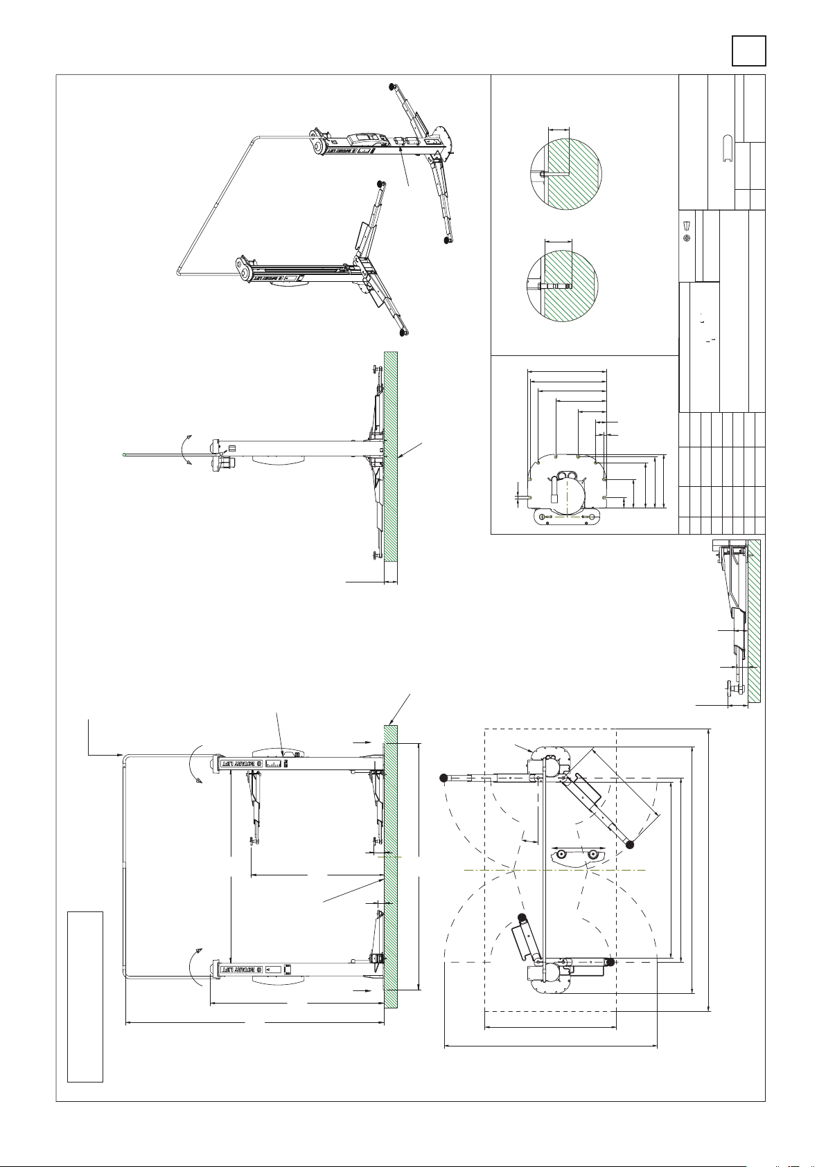
We point out the minimum requirement
of the foundation in our plans.
The condition of the local realities
for example: the ground under the
foundation) does not lie in our
responsibility. The execution of
the installation situation must be
individually specified by the planning
architect or by the engineer engaged in
statically calculations in the special case.
des Fundamentes hin, jedoch
Wir weisen in unseren Plänen
auf die Mindestanforderung
der Zustand der örtlichen
Gegebenheiten (z.B. Untergrund,
Ausführung etc.)
obliegt nicht unserer Verantwortung.
Die Ausbildung der Einbausituation
muss vom planenden Architekten
bzw. Statiker im speziellen Fall
individuell spezifiziert werden.
My
optional:
min.200*
Verlängerungen
extension kit
empfohlene Dübel / recommended anchors
HSL-3 M12/25 type
Betonqualität
quality of concrete
min.C25/30
normal bewehrt
normal armouring
Detail "H"
20
Grundplatte/base plate
105
REMOVE ALL BURRS
PROJECTION
0.8mm MIN. CORNER BREAK
THIRD ANGLE
DO NOT SCALE DRAWING
UNLESS OTHERWISE SPECIFIED:
1
Die Mindestverankerungstiefe des Dübels beachten.
Mit Estrich/Fliesen sind längere Dübel einzusetzen.
Observe the min. anchorage of the dowels. With floor
pavements use longer dowels.
Die Montagevorschrift des Dübelherstellers beachten.
600
580
Observe the regulation of the dowel manufacturer
518
385
215
82
20
410
390
345
220
80
1.6mm (>or= 305mm)
Tragfähigkeit: max.4000kg
UNLESS OTHERWISE NOTED:
capacity
ANGULAR DIMENSIONS:
OTHER DIMENSIONS: 0.8mm (<305mm)
duplicated or used except by permission and is subject to return upon request.
The design and detail illustrated in this drawing is the property of Rotary
Lift. It is being loaned with the expressed condition that it will not be
NOTES:
BY
CO NUMDATE
REV
116
96
*) Betonstärke min.200mm
ohne Belag (Fliesen/Estrich)
floor pavement/tiles
Concrete thickness
min.200mm without
Das Netzkabel wird
von oben in die
Bediensäule geführt.
Insert the power supply
cable from above
to the operating column
Bauseits an der Bediensäule bereitstellen:
Netzanschluss: 3PH,N+PE,400V,50Hz
Absicherung: 25 Ampere träge
Motorleistung: 2x 3,5 kW
Kabellänge: ca.2m, 5x4mm²
optional: Druckluft, lichte Weite 6mm, 6-10 bar
Prepared by customer at the operating column:
power supply: 3PH,N+PE,400V,50Hz
fuse: 25 Ampere, time lag
Motor power: 2x 3,5 kW
Bediensäule
optional air pressure: inner diameter 6mm, 6-10 bar
Operating column
Anschlussarmierung zum
vorhandenen Betonboden
herstellen
Produce a connection reinforcement
to the existing concrete floor
PP
"H"
cable: approx.2m, 5x 4m²
105-165
Mx
725-1430
°
5
1
2800
2680
3752
2944
2030
165max
3752
105min
OKFFB
Mx
Fundament min.4300
Mass- und Konstruktionsänderungen vorbehalten!
subject to alterations!
2643
3931
Fundament min.2000
3240
P: 24 KN / Mx: 24 K Nm / My: 21 K Nm
maximale statische Kräfte und Momente
maximum Forces and Moments
Alle Maße in Millimeter
all dimensions in millimeter
4
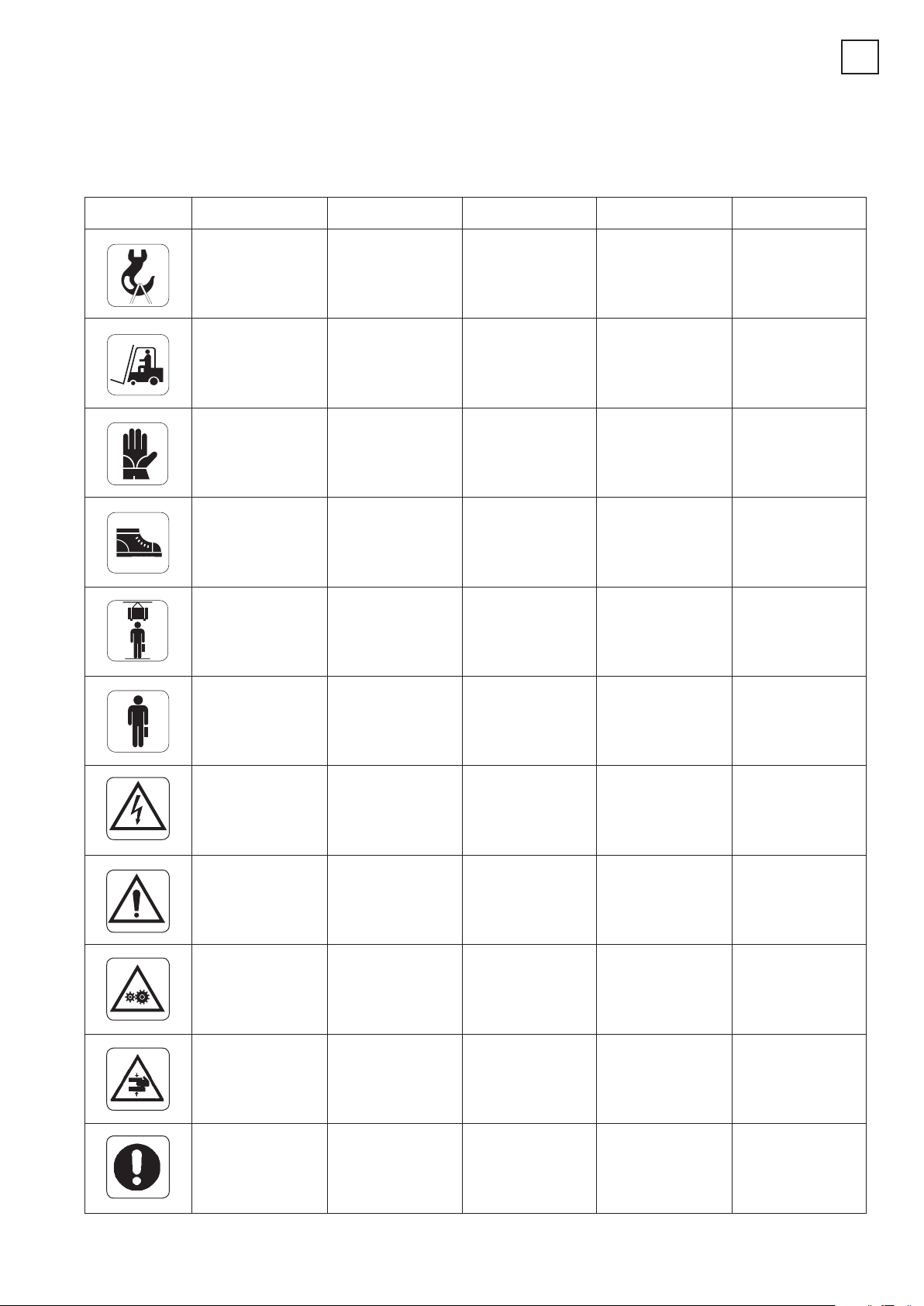
IN DER BEDIENUGSANLEITUNG VERWENDETE ZEICHEN
SYMBOLS USED IN THE MANUAL
SIMBOLOGIA UTILIZZATA NEL MANUALE
SYMBOLES UTILISÉS DANS LA NOTICE
SIMBOLOGíA UTILIZADA EN EL MANUAL
Transport mit
Gabelstapler oder
Handgabelhubwagen
Der Arbeit
angemessene
Handschuhe tragen
Der Arbeit
angemessene Schuhe
tragen
Sich nicht unter
aufgehobener Last
aufhalten oder
durchgehen
Moving with fork lift
truck or transpallets
Wear work gloves
Wear work shoes
Do not walk or stay
beneath suspended
loads
SIMBOLISYMBOLSZEICHEN
Sollevamento dall’altoLifting from aboveAnheben von oben Levage par le haut
Movimentazione con
carrello elevatore o
transpallets
Indossare guanti da
lavoro
Calzare scarpe da
lavoro
Non passare nè
sostare sotto carichi
sospesi
SYMBOLES SÍMBOLOS
Déplacement avec
chariot élévateur ou
transpalettes
Porter des gants de
travail
Mettre des
chaussures de travail
Ne pas passer et ne
pas s’arrêter
au-dessous des
charges suspendues
Elevación desde
arriba
Desplazamiento con
carretilla elevadora o
transpaletas
Llevar guantes de
trabajo
Usar zapatos de
trabajo
No pasar ni
permanecer por
debajo de cargas
suspendidas
Qualifiziertes
Fachpersonal
Gefahr: elektrische
Entladungen
Mechanische
Elemente in
Bewegung
Specialist staff
Shock hazard
Working mechanical
parts
Personale
specializzato
Pericolo di scariche
elettriche
Attenzione!Caution!Achtung! Attention! iAtención
Organi meccanici in
movimento.
SchiacciamentoCrushingQuetschgefahr Risques d’écrasement Aplastamiento
Personnel qualifié
Danger
d'électrocution
Organes mécaniques
en mouvement
Personal
especializado
Peligro de descargas
eléctricas
Órganos mecánicos
en movimiento
ObbligoObligationPflicht Obligation Obligación
5

0. ALLGEMEINE SICHERHEITSVORSCHRIFTEN
1. SICHERHEITSEINRICHTUNGEN
1.1 VERRIEGELBARER HAUPTSCHALTER
1.2 TOTMANN-SYSTEM
1.3 MECHANISCHE NOT-AUS-VORRICHTUNG
1.4 GLEICHLAUFREGELUNG DER HUBWAGEN
1.5 NOT-AUS
1.6 BEI NOT-AUS ZUGELASSENE MANÖVER
1.7 NOT-AUS-RESET
1.8 STOPP BEI TRAGMUTTERABNUTZUNG
1.9 HINWEISE ZU DEN RESTRISIKEN
1.10 AUF DER HEBEBÜHNE VORHANDENE
GEFAHRENZEICHEN
2. BESTIMMUNGSGEMÄSSE VERWENDUNG
3. TECHNISCHE DATEN
3.1 TRANSPORT UND VORINSTALLATION
4. BESCHREIBUNG DER HEBEBÜHNE
4.1 TECHNISCHE HAUPTEIGENSCHAFTEN
4.2 STEUERUNGEN DER HEBEBÜHNE
4.3 BETRIEBSTÜCHTIGKEIT
5. KONTROLLE DER
MINDESTERFORDERNISSEN FÜR DEN
AUFSTELLUNGSORT
6 AUFSTELLUNG
6.1 INSTALLATIONSANFORDERUNGEN
0. GENERAL SAFETY PRECAUTIONS
1. SAFETY DEVICES
1.1 PADLOCKABLE MAIN SWITCH
1.2 DEADMAN DEVICE SYSTEM
1.3 MECHANICAL EMERGENCY STOP
1.4 CARRIAGE HEIGHT SYNCHRONIZATION
1.5 EMERGENCY BLOCK
1.6 MANOEUVRES PERMITTED IN EMERGENCY
CONDITIONS
1.7 RESET AFTER THE EMERGENCY STOP
1.8 NUT WEAR STOP
1.9 INDICATION OF OUTSTANDING RISKS
1.10 PICTOGRAMS ON LIFT
2. INTENDED USE
3. TECHNICAL DETAILS
3.1 PRE-INSTALLATION AND MOVEMENT
4. DESCRIPTION OF LIFT
4.1 MAIN TECHNICAL SPECIFICATIONS
4.2 LIFT CONTROLS
4.3 SUITABILITY FOR USE
5. CHECKING THE MINIMUM REQUIREMENTS
FOR THE PLACE OF INSTALLATION
6 INSTALLATION
6.1 INSTALLATION REQUIREMENTS
INHALTSVERZEICHNIS
6.2 INSTALLATIONSANWEISUNGEN
6.3 KONTROLLE DER SPANNUNG
6.4 NETZANSCHLUSS
6.5 ANSCHLÜSSE
6.6 MONTAGE DES
AUSRICHTUNGSDRAHTSEILS
6.7 KOMPLETTIERUNG UND KONTROLLE
6.8 DEMONTAGE
7. ANWEISUNGEN FÜR DIE BEDIENUNG DER
HEBEBÜHNE
7.1 UNSACHGEMÄSSE BEDIENUNG DER
HEBEBÜHNE
7.2 GEBRAUCH VON ZUBEHÖRTEILEN
7.3 SCHULUNG DES BEDIENUNGSPERSONALS
7.4 VORSICHTSMASSNAHMEN
7.5 DIE STEUERUNGEN UND IHRE FUNKTIONEN
8. BETRIEBSSTÖRUNGEN
9. WARTUNG
9.1 GLEITBAHNEN
9.2 SCHMIERBEHÄLTER
9.3 TRAGMUTTER
9.4 LAGER
10. EINLAGERUNG
10.1 VERSCHROTTUNG
11. ELEKTROANLAGE
CONTENTS
6.2 INSTALLATION INSTRUCTIONS
6.3 VOLTAGE CHECK
6.4 CONNECTING UP TO THE MAINS
6.5 CONNECTIONS
6.6 FITTING THE REALIGNMENT CABLE
6.7 COMPLETION AND CHECK
6.8 DISMANTLING
7. INSTRUCTIONS FOR USING THE LIFT
7.1 IMPROPER USE OF THE LIFT
7.2 USE OF ACCESSORIES
7.3 STAFF TRAINING
7.4 IMPORTANT CHECKS TO BE MADE
7.5 DESCRIPTION AND FUNCTION OF
CONTROLS
8. TROUBLESHOOTING
9. MAINTENANCE
9.1 SLIDEWAYS
9.2 LUBRICATION TANKS
9.3 MAIN NUTS
9.4 BEARINGS
10. STORAGE
10.1 SCRAPPING
11. ELECTRICAL INSTALLATION
12. INSTALLATIONSBERICHT - PERIODISCHER
KUNDENBESUCH AUSSERORDENTLICHE WARTUNGEN UND
REPARATUREN
13. KENNZEICHNUNGSDATEN DER MASCHINE
14 ZERTIFIKAT
12. INSTALLATION REPORT - PERIODICAL VISIT
- UNSCHEDULED MAINTENANCE AND
REPAIRING
13. MACHINE IDENTIFICATION DATA
14 CERTIFICATE
0. NORME GENERALI DI SICUREZZA
1. DISPOSITIVI DI SICUREZZA
1.1 INTERRUTTORE GENERALE LUCCHETTATO
1.2 SISTEMA A UOMO PRESENTE
1.3 BLOCCO MECCANICO D'EMERGENZA
1.4 RIALLINAMENTO CARRELLI
1.5 BLOCCO DI EMERGENZA
1.6 MANOVRE PERMESSE IN CONDIZIONI DI
EMERGENZA
1.7 RESET EMERGENZA
1.8 ARRESTO USURA CHIOCCIOLE
1.9 RISCHI RESIDUI
1.10 PITTOGRAMMI PRESENTI SUL
SOLLEVATORE
2. DESTINAZIONE D’USO
3. DATI TECNICI
3.1 MOVIMENTAZIONE E PREINSTALLAZIONE
4. DESCRIZIONE DEL SOLLEVATORE
4.1 CARATTERISTICHE TECNICHE PRINCIPALI
4.2 COMANDI DEL SOLLEVATORE
4.3 ATTITUDINE ALL'IMPIEGO
5. VERIFICA DEI REQUISITI MINIMI RICHIESTI
PER LUOGO DI INSTALLAZIONE
6
INDICE
6 INSTALLAZIONE
6.1 REQUISITI PER L'INSTALLAZIONE
6.2 ISTRUZIONI PER L'INSTALLAZIONE
6.3 CONTROLLO TENSIONE
6.4 ALLACCIAMENTO RETE
6.5 COLLEGAMENTI
6.6 MONTAGGIO DEL CAVO DI RIALLINEO
6.7 COMPLETAMENTO E CONTROLLO
6.8 SMONTAGGIO
7. ISTRUZIONI PER L’USO DEL SOLLEVATORE
7.1 USO IMPROPRIO DEL SOLLEVATORE
7.2 USO DI ACCESSORI
7.3 ADDESTRAMENTO DEL PERSONALE
PREPOSTO
7.4 PRECAUZIONI D’USO
7.5 IDENTIFICAZIONE DEI COMANDI E LORO
FUNZIONE
8. INCONVENIENTI
9. MANUTENZIONE
9.1 GUIDE DI SCORRIMENTO
9.2 VASCHETTE DI LUBRIFICAZIONE
9.3 CHIOCCIOLE PORTANTI
9.4 CUSCINETTI
10. ACCANTONAMENTO
10.1 ROTTAMAZIONE
11. IMPIANTO ELETTRICO
12. RAPPORTO DI INSTALLAZIONE VISITA PERIODICA - MANUTENZIONI
STRAORDINARIE E RIPARAZIONI
13. DATI DI IDENTIFICAZIONE DELLA
MACCHINA
14 CERTIFICATO

0. NORMES GENERALES DE SECURITE
1. DISPOSITIFS DE SECURITE
1.1 INTERRUPTEUR PRINCIPAL VERROUILLABLE
1.2 SYSTÈME DE SÉCURITÉ “HOMME MORT”
1.3 ARRÊT MÉCANIQUE D’URGENCE
1.4 SYNCHRONISME DE LEVAGE
1.5 ARRÊT D’URGENCE
1.6 QUOI FAIRE EN CAS D’ARRÊT DE SECOURS
1.7 REMISE À ZÉRO DE LA SÉCURITÉ
ÉLECTRIQUE
1.8 ARRÊT USURE ECROUS
1.9 RISQUES RÉSIDUELS
1.10 PICTOGRAMMES PRÉSENTS SUR
L’ÉLÉVATEUR
2. DESTINATION D’USAGE
3. CARACTERISTIQUES TECHNIQUES
3.1 DÉPLACEMENT ET PRÉ-INSTALLATION
4. DESCRIPTION DU PONT ELEVATEUR
4.1 PRINCIPALES CARACTÉRISTIQUES
TECHNIQUES
4.2 COMMANDES DU PONT ÉLÉVATEUR
4.3 DISPOSITION POUR L'UTILISATION
5. VERIFICATION DES CARACTERISTIQUES
MINIMES REQUISES POUR LA ZONE
D’INSTALLATION
INDEX
6 INSTALLATION
6.1 CONDITIONS REQUISES POUR
L’INSTALLATION
6.2 INSTRUCTIONS POUR L’INSTALLATION
6.3 CONTRÔLE DE LA TENSION
6.4 CONNEXION AU RÉSEAU
6.5 CONNEXIONS
6.6 MONTAGE DU CÂBLE DE RÉALIGNEMENT
6.7 COMPLÈTEMENT DE L’INSTALLATION ET
CONTRÔLE
6.8 DÉMONTAGE
7. MODE D’EMPLOI DU PONT ELEVATEUR
7.1 UTILISATION INCORRECTE DU PONT
ÉLÉVATEUR
7.2 UTILISATION D’ACCESSOIRES
7.3 FORMATION DU PERSONNEL PRÉPOSÉ
7.4 PRÉCAUTIONS POUR L’EMPLOI
7.5 IDENTIFICATION ET FONCTION DES
COMMANDES
8. PANNES EVENTUELLES
9. ENTRETIEN
9.1 GLISSIÈRES
9.2 BACS DE GRAISSAGE
9.3 ECROUS PORTEURS
9.4 COUSSINETS
ÍNDICE
10. STOCKAGE
10.1 MISE À LA FERRAILLE
11. INSTALLATION ELECTRIQUE
12. RAPPORT D’INSTALLATION CONTROLE PERIODIQUE - INTERVENTIONS
D’ENTRETIEN SPECIAL ET REPARATIONS
13. DONNÉES D’IDENTIFICATION DE LA
MACHINE
14 CERTIFICAT
0. NORMAS DE SEGURIDAD
1. DISPOSITIVOS DE SEGURIDAD
1.1 INTERRUPTOR GENERAL BAJO CANDADO
1.2 SISTEMA “HOMBRE MUERTO”
1.3 BLOQUEO MECÁNICO DE EMERGENCIA
1.4 REAJUSTE DE LOS CARROS
1.5 BLOQUEO DE EMERGENCIA
1.6 MANIOBRAS PERMITIDAS EN
CONDICIONES DE EMERGENCIA
1.7 RESET DE EMERGENCIA
1.8 BLOQUEO DESGASTE TUERCAS PORTANTES
1.9 RIESGOS RESIDUOS.
1.10 PICTOGRAMAS EN EL ELEVADOR
2. DESTINACIÓN DE USO
2.1 DATOS DE IDENTIFICACION DE LA MAQUINA
3. DATOS TÉCNICOS
3.1 DESPLAZAMIENTO Y PREINSTALACIÓN
4. DESCRIPCIÓN DEL ELEVADOR
4.1 CARACTERISTICAS TÉCNICAS PRINCIPALES
4.2 MANDOS DEL ELEVADOR
4.3 APTITUD PARA EL EMPLEO
5. COMPROBACIÓN DE LA EXISTENCIA DE LOS
REQUISITOS MÍNIMOS REQUERIDOS PARA
EL SITIO DE LA INSTALACIÓN
6 INSTALACIÓN
6.1 REQUISITOS PARA LA INSTALACIÓN
6.2 INSTR3ACIÓN DEL SISTEMA ELÉCTRICO
6.3 CONTROL DE TENSIÓN
6.4 ENLACE A LA RED
6.5 CONEXIONES
6.6 MONTAJE DEL CABLE DE REALINEACIÓN
6.7 TERMINACIÓN DE LA INSTALACIÓN Y
CONTROL
6.8 DESMONTAJE
7. INSTRUCCIONES PARA EL USO DEL
ELEVADOR
7.1 USO IMPROPIO DEL ELEVADOR
7.2 USO DE ACCESORIOS
7.3 FORMACIÓN DEL PERSONAL AUTORIZADO
7.4 PRECAUCIONES DURANTE EL USO
7.5 IDENTIFICACIÓN DE LOS MANDOS Y SUS
FUNCIONES
8. INCONVENIENTES
9. MANTENIMIENTO
9.1 GUÍAS DESLIZANTES
9.2 TANQUES DE LUBRICACIÓN
9.3 TORNILLOS PATRÓN PORTANTES
9.4 COJINETES
10. DESUSO
10.1 REDUCCIÓN A RESIDUOS
11. INSTALACIÓN ELÉCTRICA
12. RELACIÓN DE INSTALACIÓN CONTROL PERIÓDICO - MANTENIMIENTO
EXTRAORDINARIO Y REPARACIONES
13. DATOS DE IDENTIFICACION DE LA
MAQUINA
14 CERTIFICADO
ZUSAMMENSETZUNG DER
ANLEITUNG
62 Seiten
(inkl. Deckblätter)
COMPOSITION OF MANUAL
62 pages
(including cover pages)
COMPOSIZIONE DEL
MANUALE
62 pagine
(comprese le copertine)
COMPOSITION DE LA
NOTICE
62 pages
(pages de la couverture
inclues
COMPOSICIÓN DEL
MANUALE
62 páginas
(incluidas las cubiertas)
7
0. ALLGEMEINE SICHERHEITSVORSCHRIFTEN
Die Hebebühne darf ausschliesslich von geschultem Fachpersonal
bedient werden und erst nachdem die Bedienungsanleitung aufmerksam
gelesen und verstanden worden ist. Der Bediener muss zur Bedienung
der Hebebühne von der Person autorisiert werden, die die Verantwortung
für die Anlage trägt.
Unbefugtes Betätigen und Änderungen an der Hebebühne sowie an den
Sicherheitseinrichtungen sind verboten. Bei Verstoss gegen diese Vorschriften lehnt der Hersteller jede Verantwortung für die daraus entstehenden Schäden ab.
Darüber hinaus sind folgende Verhaltensmassregeln einzuhalten:
- nur ROTARY Zubehöre und Ersatzteile verwenden;
- die Hebebühne ist durch autorisiertes Fachpersonal aufzustellen;
0. GENERAL SAFETY PRECAUTIONS
The lift should only be used by properly trained personnel and only after
reading and understanding this manual. The operator must be authorised
by the person in charge of the plant.
Tampering with or making changes to the lift and safety devices is forbidden. Failure to comply will result in the manufacturer being released from
all liability for any resulting damages.
Also follow these instructions:
- only use ROTARY accessories and spares;
- installation must be performed by authorised and professional personnel;
- make sure no hazardous situations occur during up or down movement
0
- sicherstellen, dass beim Hoch- und Herunterfahren der Hebebühne
keine gefährliche Situationen entstehen; ggf. die Hebebühne sofort
anhalten und die Gefährdungen beseitigen;
- die Arme sind auf die Punkte zu positionieren, die auf dem Fahrzeug
vorgesehen sind; vor dem Hublauf die Stabilität des Fahrzeugs kontrollieren; während des Hoch- und Herunterfahrens den Aufnahmepunkt des
Fahrzeugs kontrollieren;
- Es ist verboten, auf die Hubelemente zu steigen oder sich auf diesen
aufzuhalten.
- nach der Hochfahrt den Schalter auf “0” setzen;
- vor dem Anheben des Fahrzeugs durch Einsichtnahme des Klebeschildes “Lastschema” sicherstellen, dass die Last vorschriftsgemäss ist.
of the lift. If they do, stop the lift immediately and remedy the causes of the
emergency;
- the arms must be positioned at the vehicle points provided. Before
lifting, check vehicle stability. During up or down movement, check the
vehicle load bearing point;
- standing on the lifting mechanisms is forbidden;
- after lifting, position the switch on “0”;
- before lifting, check the load is correct by means of the “load diagram”
adhesive.
0. NORME GENERALI DI SICUREZZA
L’uso del sollevatore è consentito solo a personale appositamente addestrato e solo dopo aver letto e compreso il presente manuale; l’operatore
deve essere autorizzato da chi ricopre il ruolo di responsabile dell’impianto.
Sono vietate manomissioni o modifiche al sollevatore e ai dispositiovi di
sicurezza; nel caso in cui si verifichi quanto sopra scritto il costruttore si
ritiene sollevato dai danni derivati.
Seguire inoltre le seguenti indicazioni:
- usare solo accessori e ricambi ROTARY;
- l’installazione deve essere fatta da personale autorizzato e qualificato;
- controllare che durante la fase di salita e discesa non si verifichino con-
0. NORMES GENERALES DE SECURITÈ
Le pont élévateur ne peut être utilisé que par un personnel ayant suivi une
formation appropriée et ayant lu et compris le contenu de la présente
notice; l’opérateur doit être autorisé par la personne responsable de l’installation.
Il est strictement interdit de manipuler ou de modifier l’élévateur et les
dispositifs de sécurité; toute dérogation à ces instructions décline le fabricant de toute responsabilité.
Respecter entre autres les instructions suivantes:
- n’utiliser que des accessoires et des pièces de rechange ROTARY;
- l’installation doit être prise en charge par un personnel autorisé et qualifié;
- contrôler l’absence de toute condition de danger pendant les mano-
dizioni di pericolo; in tal caso arrestare immediatamente il sollevatore e
rimuovere le cause di emergenza;
- i bracci devono essere posizionati sui punti predisposti del veicolo;
prima della salita verificare la stabilità del veicolo; verificare durante la
fase di salita e discesa il punto di appoggio del veicolo;
- è vietato salire o sostare sugli organi di sollevamento;
- dopo il sollevamento posizionare l’interruttore sullo “0”;
- prima di sollevare verificare con l’adesivo “diagramma di carico” che il
carico sia corretto.
euvres de montée et de descente; en cas de danger, arrêter immédiatement l’élévateur et éliminer les causes à l’origine de la condition d’urgence;
- les bras doivent être positionnés aux points prévus par le fabricant du
véhicule: vérifier la stabilité du véhicule avant d’entreprendre la manoeuvre de levage; pendant les phases de montée et de descente, vérifier le
point d’appui du véhicule;
- Il est strictement interdit de monter ou de s’arrêter sur les organes de
levage;
- une fois le levage terminé, positionner l’interrupteur sur le “0”;
- avant d’effectuer le levage, contrôler à l'aide du “diagramme de chargement” que le chargement soit correct.
0. NORMAS GENERALES DE SEGURIDAD
El uso del elevador sólo está permitido a personal capacitado a propósito
y sólo después de haber leído y comprendido el presente manual; el operador tiene que estar autorizado por quien desempeña el cargo de responsable de la instalación.
Están prohibidas las alteraciones o modificaciones del elevador y de los
dispositivos de seguridad; en caso de que se verifique lo descrito anteriormente, se considera al constructor no responsable de los daños derivados.
Además, hay que seguir las siguientes indicaciones:
- usar únicamente accesorios y repuestos ROTARY;
- la instalación tiene que ser realizada única y exclusivamente por personal autorizado y cualificado.
8
- controlar que durante la fase de subida y bajada no se verifiquen condiciones de peligro: de ser así, detener la máquina y eliminar las causas de
emergencia;
- los brazos tienen que estar colocados en los puntos predispuestos en el
vehículo; antes de la subida, comprobar la estabilidad del vehículo, comprobar durante la fase de subida y bajada el punto de apoyo del vehículo;
- Está terminantemente prohibido subirse o pararse en los órganos de
elevación.
- después de la elevación colocar el interruptor en “O”
- antes de la elevación, comprobar con el adhesivo “diagrama de carga”
que la carga esté correcta.
1. SICHERHEITSEINRICHTUNGEN
1.1 Verriegelbarer Hauptschalter
1.2 Totmann-System
Die Hebebühne ist mit dem “Totmann”-Betriebssystem ausgerüstet. Wird die
Schalttaste losgelassen, werden die Hub- und Absenkbewegungen
unverzüglich unterbrochen.
Mechanische Not-Aus-Vorrichtung
1.3
Sollte ein Endschalter am Ende der Aufwärts- bzw. Abwärtsbewegung nicht
funktionieren, wird die Hebebühne über ein mechanisches Sperrsystem
abgestoppt.
Unter diesen Umständen die Hebebühne im umgekehrter Richtung ca. 5 - 10
cm stossweise zurückfahren.
Den Endschalter prüfen und ggf. auswechseln.
Hinweis: Ausser der mechanischen Sperre kann die obige Situation das
Abschalten des Motorwärmefühlers zur Folge haben. Es muss dann das
automatische Wiedereinschalten desselben (nach ca. 3 Minuten) abgewar
tet werden.
Gleichlaufregelung der Hubwagen
1.4
Die Entfernung oder der Umbau der Sicherheitseinrichtungen stellt eine Ver
letzung der Europäischen Sicherheitsnormen dar.
Erreicht der Höhenunterschied der Hubwagen 18 cm greift automatisch die
Überwachungsvorrichtung ein und stellt den Gleichlauf wieder her.
Alle eigenmächtigen Eingriffe oder Modifizierungen an Einrichtungen, die nicht zuvor vom Hersteller autorisiert wurden,
entheben diesen von der Haftungspflicht für dadurch verur
sachte Schäden.
1
-
-
-
1. SAFETY DEVICES
1.1 Padlockable main switch
1.2 Deadman device
The lift is equipped with a “deadman” type operative system so that up or
down movement is immediately stopped when the control reverserswitch is released.
1.3 Mechanical emergency stop
The lift is fitted with mechanical stops that trigger when the limit switch
sends warning signals, at the end of an up or down run. In these situations, jog operate the movement opposite to the previous movement for a
distance of 5-10 cm.
Check the relative limit switch and replace if necessary.
1. DISPOSITIVI DI SICUREZZA
1.1 Interruttore generale lucchettabile
1.2 Sistema a uomo presente
Il ponte è dotato di un sistema operativo del tipo "uomo presente": le operazioni di salita o di discesa, sono immediatamente interrotte al rilascio
dell'interruttore-invertitore di comando.
1.3 Blocco meccanico d'emergenza
Il ponte è dotato di arresti meccanici che agiscono in caso di anomalie del
finecorsa, al termine della corsa di salita o di discesa.
In tali situazioni comandare a scatti la manovra opposta all’operazione
precedente per una corsa di 5-10 cm.
Controllare il finecorsa interessato, ed eventualmente sostituirlo.
N.B. Oltre al blocco meccanico di cui sopra puó verificarsi il disinserimento
N.B. Besides the mechanical stop described above, the motor heat probe
might be disabled. This is automatically reset after about 3 minutes.
1.4 Carriage height synchronization
Any unauthorised modifications or tampering with the equipment
release the manufacturer from any liability for damages caused
by or related to the above mentioned acts.
Removal of or tampering with safety devices constitutes an
infringement of European Safety Regulations.
Should the difference in level of the two carriages exceed 18 mm, the
control device automatically resets the correct alignment.
della sonda termica del motore; il riarmo automatico di quest’ultima avverrà
dopo circa 3 minuti.
1.4 Riallineamento carrelli
Ogni manomissione o modifica dell'apparecchiatura non preventivamente autorizzate dal costruttore sollevano quest'ultimo da danni derivati o riferibili agli atti suddetti.
La rimozione o manomissione dei dispositivi di sicurezza
comporta una violazione delle Norme Europee sulla sicurezza.
Quando la differenza di altezza tra i due carrelli raggiunge i 18mm, il dispositivo di controllo interviene automaticamente per ripristinare il corretto
allineamento.
1. DISPOSITIFS DE SECURITE
1.1 Interrupteur principal verrouillable
1.2 Système (de sécurité "d'homme-mort")
Le pont élévateur est équipé d’un système (dit “d’homme mort”): les opérations de
montée ou de descente commandées sont immédiatement interrompues lors du
relâchement du poussoir.
1.3 Arrêt d'urgence (mécanique)
Le pont est équipé de butées mécaniques agissant à la fin de la course de levée
ou de descente, en cas de mauvais fonctionnement des fins de course. Dans ce
cas, commander par à-coups la manoeuvre opposée à l’opération précédente
pour une course de 5-10 cm. Contrôler le fin de course en question et le remplacer
au besoin.
1. DISPOSITIVOS DE SEGURIDAD
1.1 Interruptor general bajo candado
1.2 Sistema “hombre muerto”
El elevador tiene un sistema de tipo “hombre muerto”, las operaciones de
subida o descenso son interrumpidas de immediato al soltar el interruptor-invertidor de mando.
1.3 Bloqueo mecánico de emergencia
El elevador está dotado de topes mecánicos que actúan en caso de anomalías del fin de carrera, al final del recorrido de subida o de descenso.
En esos casos, mandar a intervalos la maniobra opuesta a la operación
anterior durante un recorrido de 5 - 10 cms.
Regular o sustituir el final de carrera correspondiente.
N.B. En sus du blocage mécanique ci-dessus il pourrait se produire le
déclenchement automatique de la sonde thermique du moteur. Le rétablissement de la sonde se fait automatiquement après trois minutes env.
1.4 Synchronisme de levage
La responsabilité du fabricant ne peut être mise en cause
pour les dommages dérivant de toute altération ou modification de l’équipement non autorisée préalablement par le fabricant.
La suppression ou l’altération des dispositifs de sécurité comporte une violation des Normes Européennes en matière de
sécurité.
Lorsque la différence de niveau entre les deux chariots atteint 18 mm, le
contrôleur rétablit l’alignement correct automatiquement.
NOTA: Además del tope mecánico, se puede también verificar la desactivación de la sonda térmica del motor; el rearme automático de la sonda se
verifica después de 3 minutos aproximadamente.
1.4 Reajuste de los carros
Cualquier uso indebido o modificación de la máquina que no
hayan sido autorizadas por el fabricante lo eximen de los
posibles daños que puedan derivar o estar relacionados con
los actos mencionados.
Quitar o usar indebidamente los dispositivos de seguridad
comporta una violación de las Normas Europeas de Seguridad.
Cada vez que se produce una diferencia en altura de los carros igual a 18
mm, el dispositivo de control se activa automáticamente, con el fin de
reestablecer la nivelación correcta.
9

1.5 Not-Aus
Not-Aus-Abschaltung bei:
- Höhenunterschied zwischen den beiden Hubwagen über 35 mm;
- Motorenstopp;
- Bruch des Ausrichtungsdrahtseils.
1.6 Bei Not-Aus zugelassene Manöver
- Bei Not-Aus der Hebebühne (siehe obiger Abschnitt) darf diese über die
Tasten weder hoch- noch heruntergefahren werden. Zur Wiederherstellung des Betriebs den Kundendienst zu Rate ziehen.
- Ist das Fahrzeug auf den Boden zu bringen, die Hubwagen manuell über
die Riemenscheiben herunterfahren.
1
1.7 Stopp bei Tragmutterabnutzung
Wird die Hebebühne über die in Abschitt 9.3 angegebene Grenze hinaus
benutzt, greift die Tragmutterabnutzungs-Vorrichtung ein.
Der Eingriff dieser Vorrichtung lässt die Last herunterfahren, begrenzt
aber das Hochfahren auf eine Höhe von 30 cm vom Fussboden.
1.5 Emergency block
This type of block occurs in the case of:
- the carriages more than 35 mm out of alignment;
- motor block
- breakage of alignment cable.
1.6 Manoeuvres permitted in emergency conditions
- When the lift is in the emergency state (see previous paragraph), no
operation is allowed by means of the “lowering” or “lifting” push buttons.
To reset the operation mode, apply to our After Sales Service.
- To remove the car from the lift, turn the pulleys by hand.
1.5 Blocco di emergenza
Questo tipo di blocco interviene in caso di:
- disallineamento dei carrelli superiore a 35 mm;
- blocco dei motori
- rottura del cavetto di allineamento.
1.6 Manovre permesse in condizioni di emergenza
- Quando il sollevatore si trova in condizione di emergenza (vedi paragrafo
precedente) non è consentita nessuna manovra di salita o discesa mediante
i comandi; per il ripristino del funzionamento contattare il Servizio Assistenza
- Se occorresse togliere il veicolo dal ponte è possibile far scendere i carrelli
azionando manualmente le pulegge.
1.7 Nut wear stop
If the lift is operated even when the limit marks are aligned (see par. 9.3),
the safety system becomes operative. This intervention allows to move
down the charge but, afterwards, the carriage lifting will be stopped 30
cm from the floor.
1.7 Arresto usura chiocciole
Utilizzando il sollevatore oltre il limite indicato al par. 9.3 si avrà l’intervento
dell’arresto usura chiocciola.
L’intervento del dispositivo consente la discesa del carico ma impedisce il
sollevamento oltre i 30 cm da terra.
1.5 Arrêt d’urgence
Ce type d’arrêt intervient lorsque:
- le désalignement des chariots est supérieur à 35 mm;
- les moteurs s’arrêtent;
- le câble d’alignement se casse.
1.6 Quoi faire en cas d’arrêt de secours
- Lorsque le pont-élévateur est dans l’arrêt de secours (voir par.
précédent), on ne peut pas commander par les boutons-poussoirs ni la
montée ni la descente. Pour rétablir le fonctionnement, il faut s’adresser
au Service Après-Vente.
- Pour descendre le véhicule du pont, baisser les chariots en actionnant
les poulies manuellement.
1.5 Bloqueo de emergencia
Este tipo de bloqueo se activa en caso de:
- desalineación de los carros superior a 35 mm;
- bloqueo de los motores;
- ruptura del cablecito de alineación.
1.6 Maniobras permitidas en condiciones de emergencia
- Cuando el elevador se encuentra en condiciones de emergencia (ver
párrafo anterior) ninguna maniobra de subida o bajada está permitida por
medio de los pulsadores. Para reestablecer el funcionamiento del elevador, consultar con el Servicio Post-Venta.
- Si fuera necesario remover el vehículo del elevador, se pueden bajar los
carros activando manualmente las poleas.
1.7 Arret usure ecrous
Si le pont élévateur continue à travailler au délà de la limite indiquée au
par. 9.3, on provoquera l’actionnement de l’arrêt de sécurité usure écrou.
L’actionnement du dispositif permet la descente de la charge mais après
le pont sera arrêté à 30 cm env. du sol.
1.7 Bloqueo desgaste tuercas portantes
Insistiendo en el uso del elevador más allá del límite indicado en el párrafo
9.3, se produce el desgaste total y la parada mecánica de la tuerca. La
activación de este dispositivo permite la bajada de la carga, pero impide
la elevación más allá de los 30 cm desde el suelo.
10

1
PAGINA LASCIATA INTENZIONALMENTE BIANCA
PAGE INTENTIONELLY LEFT BLANK
ABSICHTLICH LEER GELASSENE SEITE
PAGE INTENTIONELLEMENT VIDE
PAGINA VACÍA INTENCIONADAMENTE
11
1
Refer to full operating manual.
The lift may only be operated by authorized staff.
The lift must be used for its intended purpose only.
Do not exceed the load capacity specifi ed on the Serial plate.
The weight distribution at the front/back may not exceed the value
given in the full operating manual.
Comply with the statutory Health and Safety regulations.
Do not carry persons on the lift.
Apply the vehicle handbrake after driving onto the lift and before
lifting the vehicle.
The main switch is also an emergency stop switch .In case
of emergency, turn the switch to "O".
Secure the lift against unauthorized use by locking the main switch.
Obstacles must be kept out of range of moving load and lift.
1. BEFORE LOADING:
Check that the lift is in full working order. Refer to the
Operating and Service Manual.
The lift must be fully lowered, there must be no objects, grease and
oil on the arms and rubber pads and people in the work area.
Swing the arms with the adapters free of oil and grease all the way
to the drive -through position.
Main switch to "ON".
Swing the arms under the vehicle and position the adapters on the
pick-up points recommended by the vehicle manufacturer.
If necessary, use optional adapters.
2. LIFTING:
There must be No one on the lift or in the vehicle when lifting
and lowering.
Press the "UP" button. Before the adapters make contact with
the vehicle, stop the lift .Ensure that all the arm restraints are fully engaged.
If necessary, move the arm slightly until the restraint fully engages
in the restraint gear. Do Not hit the pins with a hammer, since doing so
could damage the restraint gear teeth!
Do not leave parts lying around on the lift and on the vehicle you want to lift.
When fi tting or disassembling heavy vehicle parts, make sure that the
centre of the vehicle does not shift! The vehicle must be secured beforehand.
The vehicle must always rest on 4 pick-up points or be secured
against movement.
Only continue the lifting process up to the desired height if the vehicle
is stable.
Do not leave the lift at its full rise for long periods.
Lower the lift onto the safety latches.
3. WHEN LIFTING:
Prevent the vehicle from rocking.
The vehicle doors must be closed when raising and lowering.
Monitor the load and the lift when raising and lowering.
Do not loiter within range of the moving load and lift when raising
and lowering.
Do not climb onto the raised vehicle or the lift.
4. BEFORE LOWERING THE LIFT:
Remove obstacles from under the car and lift.
Do not loiter within the work area of the lift.
5. LOWERING:
Press the "UP" button, if you want to raise the lift out of the
locking mechanism .
Press the "Lower" button and lower to the desired height .If the lift
is M-version , Operate the release lever down at the same time.
6. DRIVING OFF:
The lift must be fully lowered.
Swing the arms all the way to the drive-through position .Only then
move the vehicle.
7. SWITCHING OFF:
When the lift is not in use, turn the main switch to "OFF".
8. TROUBLESHOOTING AND MAINTENANCE:
Refer to the operating and Service Manual.
12071
4
5
6
4
1
2
3
12
1
2
3
4
5
6
7
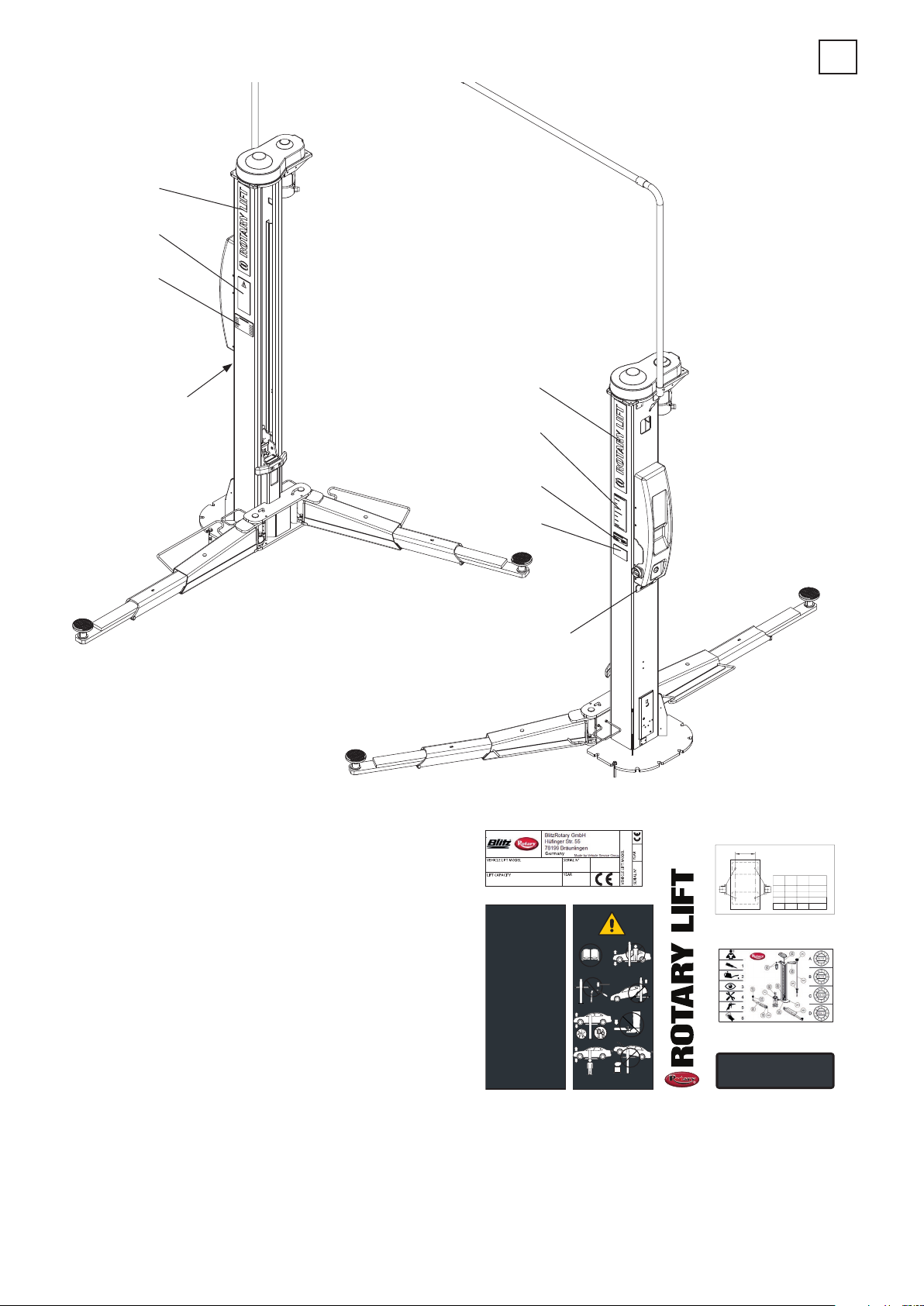
999921600
999909850
999921570
999921580
999921590
999921610
999912071
STICKER (Q=4000Kg)
STICKER (INSTRUCTIONS)
STICKER (SERIAL NUMBER)
STICKER (ROTARYLIFT)
STICKER (WARNING)
STICKER (MAINTENANCE)
STICKER (LOAD DISTRIBUTION)
7
1
3
Refer to full operating manual.
The lift may only be operated by authorized staff.
The lift must be used for its intended purpose only.
Do not exceed the load capacity specifi ed on the Serial plate.
The weight distribution at the front/back may not exceed the value
given in the full operating manual.
Comply with the statutory Health and Safety regulations.
Do not carry persons on the lift.
Apply the vehicle handbrake after driving onto the lift and before
lifting the vehicle.
The main switch is also an emergency stop switch .In case
of emergency, turn the switch to "O".
Secure the lift against unauthorized use by locking the main switch.
Obstacles must be kept out of range of moving load and lift.
1. BEFORE LOADING:
Check that the lift is in full working order. Refer to the
Operating and Service Manual.
The lift must be fully lowered, there must be no objects, grease and
oil on the arms and rubber pads and people in the work area.
Swing the arms with the adapters free of oil and grease all the way
to the drive -through position.
Main switch to "ON".
Swing the arms under the vehicle and position the adapters on the
pick-up points recommended by the vehicle manufacturer.
If necessary, use optional adapters.
2. LIFTING:
There must be No one on the lift or in the vehicle when lifting
and lowering.
Press the "UP" button. Before the adapters make contact with
the vehicle, stop the lift .Ensure that all the arm restraints are fully engaged.
If necessary, move the arm slightly until the restraint fully engages
in the restraint gear. Do Not hit the pins with a hammer, since doing so
could damage the restraint gear teeth!
Do not leave parts lying around on the lift and on the vehicle you want to lift.
When fi tting or disassembling heavy vehicle parts, make sure that the
centre of the vehicle does not shift! The vehicle must be secured beforehand.
The vehicle must always rest on 4 pick-up points or be secured
against movement.
Only continue the lifting process up to the desired height if the vehicle
is stable.
Do not leave the lift at its full rise for long periods.
Lower the lift onto the safety latches.
3. WHEN LIFTING:
Prevent the vehicle from rocking.
The vehicle doors must be closed when raising and lowering.
Monitor the load and the lift when raising and lowering.
Do not loiter within range of the moving load and lift when raising
and lowering.
Do not climb onto the raised vehicle or the lift.
4. BEFORE LOWERING THE LIFT:
Remove obstacles from under the car and lift.
Do not loiter within the work area of the lift.
5. LOWERING:
Press the "UP" button, if you want to raise the lift out of the
locking mechanism .
Press the "Lower" button and lower to the desired height .If the lift
is M-version , Operate the release lever down at the same time.
6. DRIVING OFF:
The lift must be fully lowered.
Swing the arms all the way to the drive-through position .Only then
move the vehicle.
7. SWITCHING OFF:
When the lift is not in use, turn the main switch to "OFF".
8. TROUBLESHOOTING AND MAINTENANCE:
Refer to the operating and Service Manual.
2 5 4 1
7
RIPARTIZIONE DEL CARICO
C
LOAD DISTRIBUTION
GEWICHT VERTEILUNG
REPARTITION DE CHARGE
REPARTICION DE LA CARGA
P1(P2)
C
P2kgP1
mm
kg
Q
2250
750
700
2435
815
800
P2(P1)
2700
900
900
100030001000
6
TOTAL LIFT CAPACITY
4000 KG
Q=P1+P2
3000
3250
3600
4000
kg
EN1493-2010
1
1.8 Hinweise zu den Restrisiken
BEI DER ENTWICKLUNG UNSERER HEBEBÜHNE WURDEN STRENGE NORMEN ZUR ÜBEREINSTIMMUNG MIT DEN IN DEN EINSCHLÄGIGEN RICHTLINIEN VORGESCHRIEBENEN ANFORDERUNGEN ANGEWANDT.
DIE ANALYSE DER RISIKEN WURDE MIT GRÖSSTER SORGFALT AUSGEFÜHRT UND DIE GEFÄHRDUNGEN WURDEN, SOWEIT MÖGLICH, BESEITIGT.
EVENTUELLE RESTRISIKEN WERDEN IN DIESER BEDIENUNGSANLEITUNG UND AUF DEN GEFAHRENZEICHEN AUF DER AUSRÜSTUNG ANGEZEIGT.
1.9 Auf der Hebebühne vorhandene Gefahrenzeichen
SIEHE ABB.
EVTL. BESCHÄDIGTE GEFAHRENZEICHEN SIND BEI DER ROTARY ANZUFORDERN UND ZU ERSETZEN.
1.8 Indication of outstanding risks
OUR LIFT HAS BEEN MANUFACTURED ACCORDING TO THE MOST STRINGENT STANDARDS REQUIRED BY APPLICABLE DIRECTIVES.
RISK ANALYSIS HAS BEEN CAREFULLY MADE AND ALL HAZARDS HAVE, AS FAR AS POSSIBLE, BEEN ELIMINATED. ANY OUTSTANDING RISKS ARE
EVIDENCED IN THIS MANUAL AND ON THE MACHINE BY PICTOGRAMS.
1.9 Pictograms on lift
SEE FIG.
IN THE EVENT OF THESE PICTOGRAMS BEING DAMAGED, THEY MUST BE REPLACED BY NEW ONES AVAILABLE FROM ROTARY.
1.8 Indicazioni dei rischi residui
IL NOSTRO SOLLEVATORE È STATO REALIZZATO APPLICANDO SEVERE NORME PER LA RISPONDENZA AI REQUISITI RICHIAMATI DALLE DIRETTIVE
PERTINENTI.
L'ANALISI DEI RISCHI È STATA EFFETTUATA ACCURATAMENTE ED I PERICOLI SONO STATI, PER QUANTO POSSIBILE, ELIMINATI.
EVENTUALI RISCHI RESIDUI SONO EVIDENZIATI NEL PRESENTE MANUALE E SULLA MACCHINA MEDIANTE PITTOGRAMMI DI ATTENZIONE.
1.9 Pittogrammi presenti sul sollevatore
VEDI FIGURA.
NEL CASO CHE QUESTI PITTOGRAMMI SI DANNEGGINO È NECESSARIO SOSTITUIRLI RICHIEDENDOLI ALLA ROTARY.
1.8 Informations sur les risques résiduels
L’ÉLÉVATEUR OBJET DE LA PRÉSENTE NOTICE A ÉTÉ FABRIQUÉ DANS LE RESPECT DE NORMES SÉVÈRES POUR RÉPONDRE AUX QUALITÉS REQUISES PAR LES DIRECTIVES RÉGISSANT CES APPAREILS.
UNE ANALYSE ATTENTIVE DES RISQUES A ÉTÉ RÉALISÉE ET LES DANGERS ONT ÉTÉ ÉLIMINÉS DANS LA MESURE DU POSSIBLE.
LES RISQUES RÉSIDUELS ÉVENTUELS ONT ÉTÉ SIGNALÉS DANS LA PRÉSENTE NOTICE ET SUR LA MACHINE AU MOYEN DE PICTOGRAMMES.
1.9 Pictogrammes présents sur l’élévateur
VOIR FIGURE
LES PICTOGRAMMES ENDOMMAGÉS DOIVENT ÊTRE REMPLACÉS. S’ADRESSER DIRECTEMENT À LA SOCIÉTÉ ROTARY.
1.8 Indicaciones de los riesgos residuos
NUESTRO ELEVADOR SE HA CONSTRUIDO APLICANDO NORMAS SEVERAS PARA RESPONDER A LOS REQUISITOS EXIGIDOS POR LAS NORMATIVAS
PERTINENTES.
EL ANÁLISIS DE LOS RIESGOS SE EFECTÚO CON EL MÁXIMO CUIDADO Y LOS PELIGROS FUERON, EN LO QUE FUE POSIBLE, ELIMINADOS.
EVENTUALES RIESGOS RESIDUOS SE EVIDENCIAN EN EL PRESENTE MANUAL Y EN LA MÁQUINA MEDIANTE PICTOGRAMAS DE CUIDADO.
1.9 Pictogramas en el elevador
VER FIG.
EN EL CASO DE QUE ESTOS PICTOGRAMAS SE ESTROPEEN, ES NECESARIO SUSTITUIRLOS, SOLICITÁNDOLOS A LA EMPRESA ROTARY
13
2152
P1P2
4000 Kg
P1 P2
14

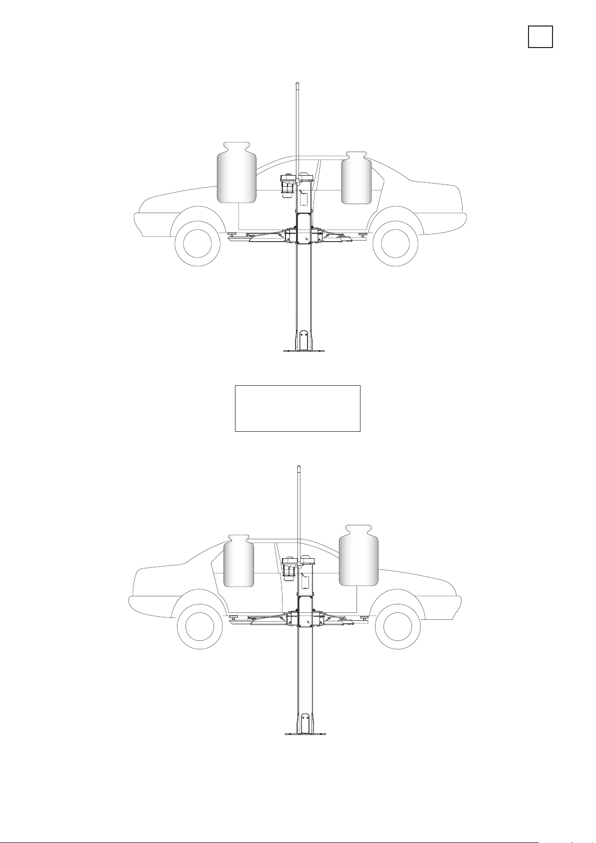
2. BESTIMMUNGSGEMÄSSE VERWENDUNG
Das Produkt ist zum Heben von Fahrzeugen vorgesehen. Die entsprechende Tragfähigkeit ist auf dem Seriennummernschild angegeben.
Gestattet wird das Heben von Fahrzeugen, die den folgenden Anforderungen entsprechen:
- Gewicht, das die Tragfähigkeit der Hebebühne nicht überschreitet.
- Lastverteilung auf den Abstützpunkten
• 4000Kg= 1—4 : 3—4 (umkehrbar)
- Mindestabstand der Hebepunkte (Spurweite): 1000 mm
2. INTENDED USE
The product is designed for lifting vehicles. The capacity is indicated on
the serial number plate.
Vehicles having the following characteristics may be lifted:
- weight not exceeding lift capacity
- load distribution on supporting points
• 4000Kg= 1—4 : 3—4 (reversible)
- minimum distance of pickup points (track): 1000 mm
2. DESTINAZIONE D’USO
Bei geringerem Abstand wird die Tragfähigkeit der Hebebühne reduziert.
In solchen und anderen, nicht von dieser Anleitung vorgesehenen Fällen
den Hersteller zu Rate ziehen.
- Die Hebebühne darf ausschliesslich in geschlossenen Räumen, wo
weder Explosions- noch Brandgefahr besteht, gefahren werden.
- Die Hebebühne ist nicht zum Waschen von Fahrzeugen geeignet.
For lower distance values, the lift capacity will be reduced. In this case or
in other cases not covered by this manual, the manufacturer should be
contacted.
- The lift may only be used in enclosed areas where there is no danger of
explosion or fire.
- The lift is not suitable for use where vehicle washing is contemplated.
Il prodotto è destinato al sollevamento di autoveicoli; la portata è quella
indicata nella targhetta matricola.
E’ consentito il sollevamento di autoveicoli rispondenti ai seguenti requisiti:
- peso non superiore alla portata del sollevatore
- ripartizione del carico sui punti di appoggio
• 4000Kg= 1—4 : 3—4 (reversibile)
distanza minima dei punti di sollevamento (carreggiata): mm.1000
2. DESTINATION D’USAGE
Le pont élévateur est destiné au levage de véhicules; la portée est celle
indiquée sur la plaque matricule.
Il ne peut être utilisé que pour le levage de véhicules répondant aux
caractéristiques suivantes:
- le poids ne doit pas dépasser la portée du pont élévateur,
- distribution de la charge sur les points d’appui
• 4000Kg= 1—4 : 3—4 (réversible) VOIR TABLEAU page 12
- distance minimale entre les points de levage (voie): 1000 mm.
2. DESTINACIÓN DE USO
Per valori di distanza inferiori, la portata del sollevatore viene ridotta. Pertanto in questi casi o per altri non contemplati nel presente manuale, sarà
opportuno contattare il costruttore.
- l’uso del sollevatore è consentito esclusivamente all’interno di locali
chiusi, ove non sussistano pericoli di esplosione o incendio.
- il sollevatore non è idoneo ad un utilizzo che preveda il lavaggio dei veicoli.
Pour des valeurs de distance inférieures, la portée du pont élévateur est
réduite. Dans ce cas ou d’autres qui ne sont pas prévus dans la présente
notice, il sera opportun de prendre contact avec le fabricant.
- le pont élévateur ne peut être utilisé qu’à l’intérieur de locaux fermés, à
l’abri de tout risque d’explosion ou d’incendie.
- le pont élévateur ne peut être utilisé pour laver les véhicules.
El producto está destinado a la elevación de autovehículos; la capacidad
está indicada en la placa de matrícula.
Está permitida la elevación de autovehículos que respondan a las siguientes características:
- peso no superior a la capacidad del elevador
- distribución de la carga en los puntos de apoyo
• 4000Kg= 1—4 : 3—4 (reversible) VEASE LA TABLA en la pág. 12
- distancia mínima de los puntos de elevación (carril): 1000 mm.
Para valores de distancia inferiores, la capacidad del elevador se reduce.
Por tanto, en esos casos y para otros no contemplados en el presente
manual, será conveniente ponerse en contacto con el fabricante.
- El uso del elevador está permitido exclusivamente en el interior de locales cerrados, en los que no exista peligro de explosión o incendio.
- El elevador no es adecuado para usos que prevean el lavado de vehículos.
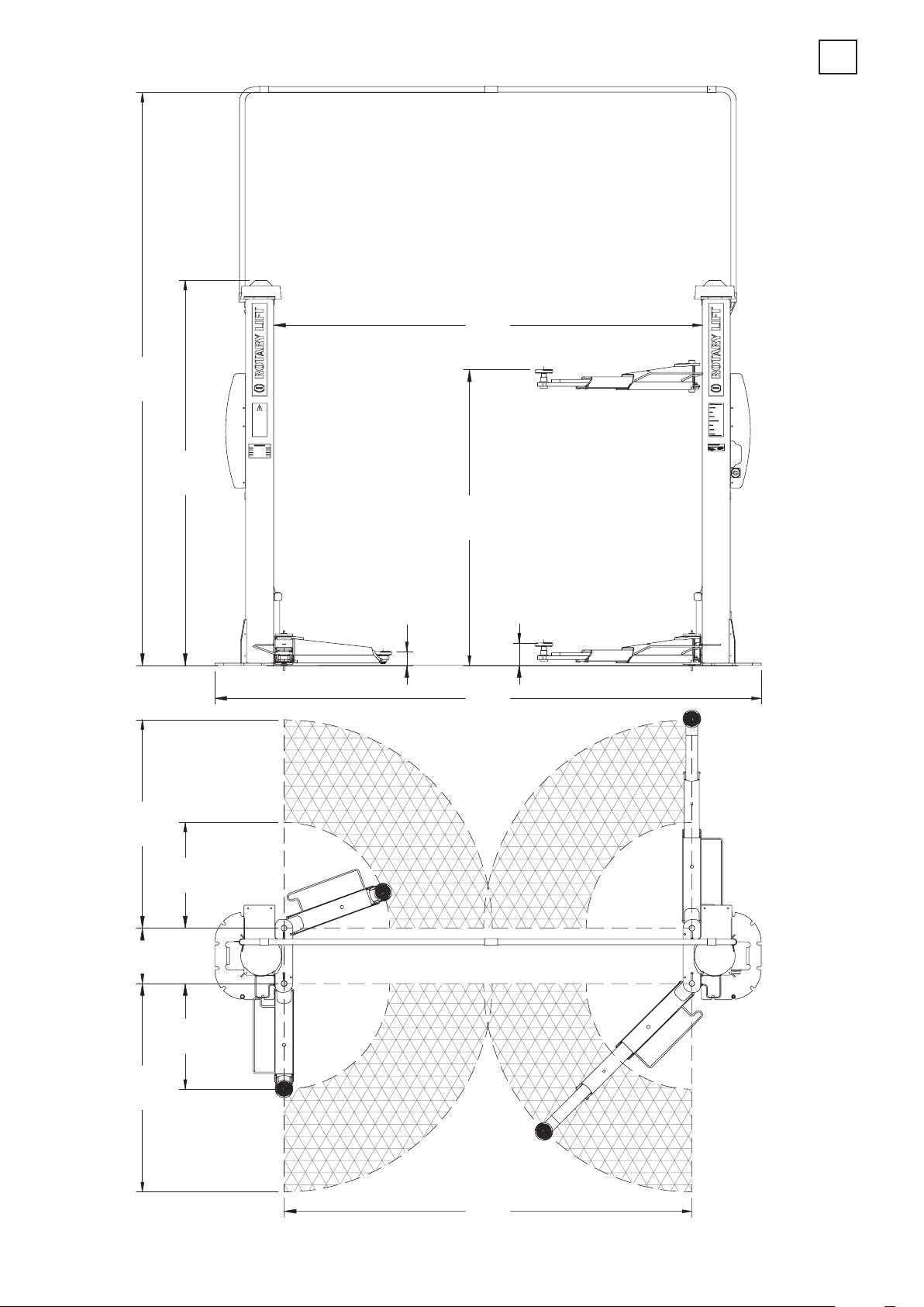
2944
1430
2800
1430
3931
380
3
2643
725
2030
95 min
3752
155 max
16
725

3. TECHNISCHE DATEN
Tragkraft 4000 kg
Motorstärke 2 x Dreiphasenmotor
230-400V - 50HZ - 3,5kW
Gewicht 740 kg
Geräuschpegel ≤70 dB (A)
3. TECHNICAL DATAILS
Capacity 4000 kg
Motors 2 x 3-phase motor
230-400V - 50HZ - 3,5kW
Weight 740 kg
Noise level ≤70 dB (A)
3
3. DATI TECNICI
Portata 4000 kg
Motorizzazione 2 motori trifase
230-400V - 50Hz - 3,5kW
Peso 740 kg
Rumorosità ≤70 dB (A)
3. CARACTERISTIQUES TECHNIQUES
Capacité 4000 kg
Puissance moteur 2 x moteur triphasé
230-400V - 50HZ - 3,5kW
Poids 740 kg
Niveau de bruit ≤70 dB (A)
3. DATOS TECNICOS
Capacidad 4000 kg
Potencia motor 2 x motor trifásico
230-400V - 50HZ - 3,5kW
Peso 740 kg
Nivel de ruido ≤70 dB (A)
17
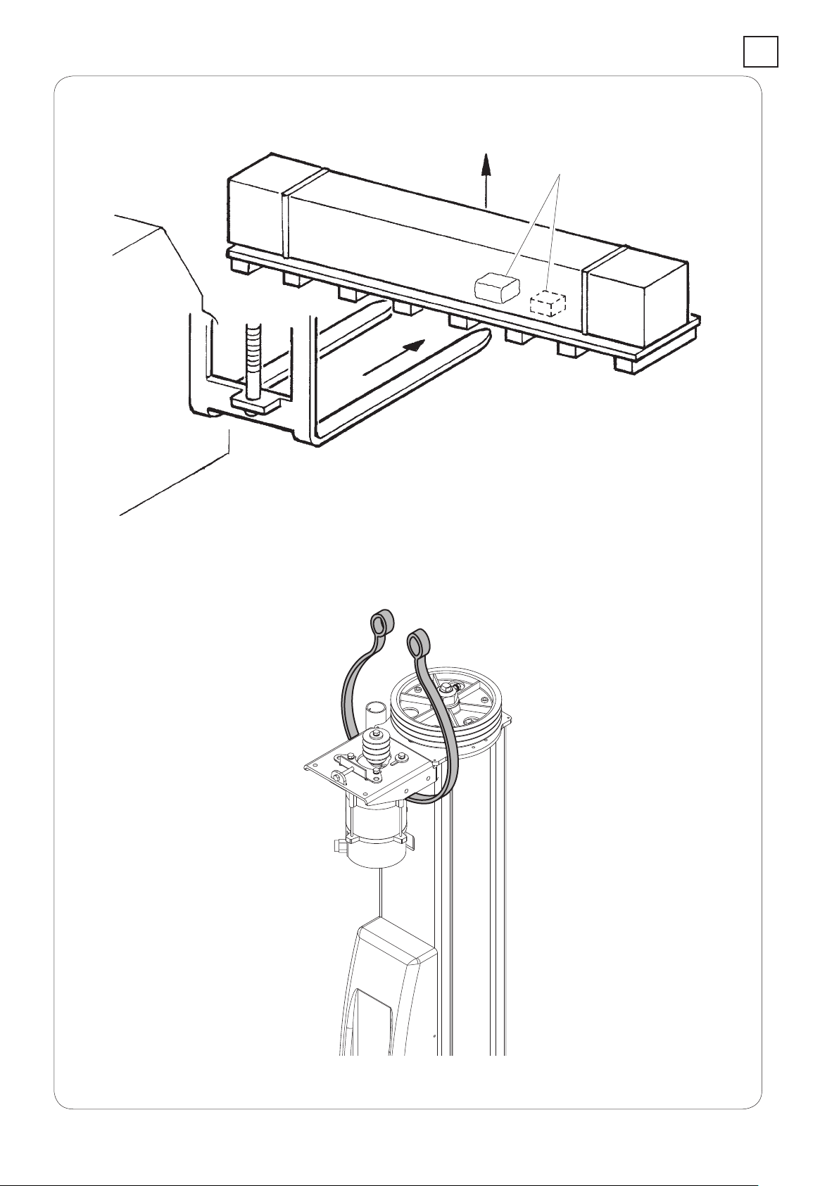
A
3
kg 400
18

3
3.1. Transport und vorinstallation
- Die Hebebühne wird gemäss Abbildung geliefert.
- Die Verpackung (A) enthält Zubehörteile und Kleinteile zur Komplettierung des Zusammenbaus.
- Beim Anheben gemäss Abbildung vorgehen.
- Vorsichtig die verschiedenen Elemente zum Ort, wo die Verpackung
entfernt wird, transportieren.
- Für die Transportmanöver der Einrichtung zum ausgesuchten Aufstellungsort (oder bei weiteren Transportmanövern) folgende Punkte
beachten:
- Vorsichtig anheben, die Last ordnungsgemäss mit geeigneten, sich in
einwandfreiem Zustand befindenden Hilfsmitteln stützen. Dabei die auf der
Abbildung angegebenen Einhakungspunkte berücksichtigen.
3.1 Pre-installation and movement
- The lift is dispatched as shown in the illustration.
- Package (A) contains the accessories and the small parts for assembly
completion.
- Lifting must be done as shown in the illustration.
- Raise with care and move the various units to the unpacking site.
- Proceed as follows when moving the machine to the chosen installation
point (or for subsequent re-positioning):
- lift with care, using suitable means of load support which are in perfect
working order and using the special hooking points as shown in the illustration.
- avoid sudden jolts and pulling, watch out for uneven surfaces, bumps
etc..
- Unerwartete Erhöhungen und Ruckbewegungen meiden. Vorsicht bei
Unebenheiten, Querrinnen usw.
- Besondere Vorsicht bei herausstehenden Teilen: Hindernisse, schwierige Durchgänge usw.
- Der auszuführenden Arbeit angemessene Kleidung und individuelle
Schutzvorrichtungen tragen.
- Die entfernten Verpackungsteile an einem für Kinder und Tiere unzugänglichen Sammelplatz bis zum Entsorgen aufbewahren.
- Bei Anlieferung die Verpackung auf ihre Vollständigkeit überprüfen.
Nach dem Auspacken kontrollieren, ob die Ware evtl. Beschädigungen
aufweist.
- take special care with outjutting parts: obstacles, difficult throughways,
etc..
- wear suitable clothing and protective gear.
- after removing the various packaging materials, check that these are
taken to special waste collecting areas inaccessible to children and animals where they will subsequently be disposed of.
- on receiving the goods, check that the packaging has not been opened.
Once unpacked, check that nothing has been damaged.
3.1 Movimentazione e preinstallazione
- il sollevatore viene spedito solitamente come illustrato in figura.
- La confezione (A) contiene gli accessori e le minuterie per il completamento dell’assemblaggio.
- Le operazioni di sollevamento devono essere eseguite come da figura.
- Sollevare con cautela e trasportare i vari gruppi nel luogo ove avverrà il
disimballo.
- Per lo spostamento della macchina nel punto prescelto per l’installazione
(o per una successiva ridisposizione) assicurarsi di:
- sollevare con cautela, adoperando adeguati mezzi di sostegno del carico, in perfetta efficienza, utilizzando gli appositi punti di aggancio come
indicato in figura.
3.1 Déplacement et pré-installation
- Le pont élévateur est livré comme illustré à la figure.
- L’emballage (A) contient les accessoires et les petites pièces pour compléter l’assemblage.
- Les opérations de levage doivent être réalisées comme indiqué à la figure.
- Soulever avec attention et transporter les différents groupes à l’endroit
choisi pour le déballage.
- Pour le déplacement de la machine à l’endroit choisi pour l’installation
(ou dans le cas d’une réinstallation successive) s’assurer de:
- soulever avec attention, en utilisant des moyens de soutien de la charge
appropriés, parfaitement efficaces et en utilisant les points d’attelage
comme indiqué à la figure.
- evitare sobbalzi e strattoni improvvisi, prestare attenzione a dislivelli,
cunette, ecc. ...;
- prestare la massima attenzione alle parti sporgenti: ostacoli, passaggi
difficoltosi, ecc. ...;
- indossare adeguati indumenti e protezioni individuali;
- dopo aver rimosso le varie parti dell’imballo, riporle in appositi luoghi di
raccolta inaccessibili a bambini e animali per poi essere smaltite;
- verificare al momento dell’arrivo l’integrità dell’imballo e a disimballo
avvenuto che non vi siano danneggiamenti.
- éviter les secousses et les à-coups imprévus, faire attention aux différences de niveau, aux défoncements, etc...;
- prêter un maximum d’attention aux parties saillantes: obstacles, passages difficiles, etc...;
- porter des vêtements appropriés et des protections individuelles;
- après avoir retiré les différentes parties de l’emballage, les déposer
dans des endroits de ramassage spéciaux, inaccessibles aux enfants et
aux animaux, et les éliminer.
- au moment de la livraison, vérifier l’intégrité de l’emballage et, au moment
du déballage, vérifier que le matériel ne soit pas endommagé.
3.1 Desplazamiento y preinstalación
- El elevador se envía como se indica en la figura.
- El paquete (A) contiene los accesorios necesarios para completar el
ensamblaje.
- Las maniobras de elevación tienen que realizarse como aparece en la
figura.
- Elevar con cuidado y transportar los distintos grupos al sitio donde tendrá lugar el desembalaje.
- Para mover la máquina en el punto elegido para su instalación (o para
una nueva colocación), hay que asegurarse de:
- elevar con cuidado, utilizando medios de soporte de la carga adecuados,
en perfecto estado, y los correspondientes puntos de enganche como
indica la figura;
- evitar movimientos bruscos y repentinos, prestar atención en los desniveles, cunetas, etc...;
- prestar la máxima atención en las partes que sobresalen: obstáculos,
pasos dificultosos, etc...;
- llevar prendas y protecciones individuales adecuadas;
- una vez que se han quitado las distintas partes del embalaje, hay que
ponerlo en los correspondientes sitios de recogida, que no estarán al
alcance de niños o de animales, para ser eliminados después;
- asegurarse cuando llega el elevador de que el embalaje esté íntegro y
cuando se ha desembalado comprobar que no haya sufrido daños.
19
 Loading...