

Rotary AR43-5MB, SM40LT, SM40-47BMW, SM40, SM55-M51VAS Operating And Maintenance Manual
...
O
P
E
R
A
T
I
N
G
A
N
D
M
A
I
N
T
E
N
A
N
C
E
M
A
N
U
A
L
© Rotary Lift, 03/2013 CO6941.3 LP20100 OM20121 Rev.D 03/2013
4-Post Lift
AR43-5MB,
SM40, SM40-47BMW,SM40LT,
SM55-M51VAS, SM60


EC Declaration of Conformity
Pursuant to EC Directive 2006/42/EC on Machinery (Annex II A)
Name and address of manufacturer BlitzRotary GmbH
Hüfinger Str.55
78199 Bräunlingen,
Deutschland
This declaration relates solely to the machine as configured when launched onto the commercial market;
parts which have been added by the end user and/or modifications made following purchase remain unaffected. Unauthorised modifications or changes to this machine invalidate this Declaration.
We hereby declare that the machine described below,
Product designation: 4-post lift
Series/type designation:
Load capacity 4000 kg SM40-47, SM40-51, SM40AT-47, SM40AT-51, AR43-5MB,
SM40-47BMW
Load capacity 5500 kg SM55-M51 VAS
Load capacity 6000 kg SM60-51, SM60-55, SM60AT-51, SM60AT-55
Load capacity 4000/3000 kg SM40LT-47, SM40LT-51
SM40LT-AT-47, SM40LT-AT-51
Machine/serial number: ...................................................
Year of manufacture: 20…
complies with all key provisions of Machinery Directive 2006/42/EC.
Furthermore, the machine complies with the provisions of the Electromagnetic Compatibility Directive
2004/108/EC and the Low Voltage Directive 2006/95/EC
(safety standards have been met pursuant to Annex I, No. 1.5.1 of the Machinery Directive 2006/42/EC).
Related harmonised standards:
EN 1493: 2010 Vehicle lifts
EN ISO 12100-1: 2003 Safety of machinery – basic concepts
EN ISO 12100-2: 2003 Safety of machinery – basic concepts
EN 60204-1:2006+7/2007 Electrical equipment of machines
EN 349:1993+A1:2008 Safety of machinery –Minimum distances
EN ISO 13850:2008 Safety of machinery – emergency stops
EN ISO 14121-1:2007 Safety of machinery – risk assessment
Related miscellaneous technical standards and specifications:
BGG 945 Inspection of lifts
BGR 500 Use of work equipment
BGV A3 Accident Prevention Regulation relating to Electrical installations
and Equipment
Name of person authorized to compile the technical documentation:
Mr. Pohl, Hüfinger Str. 55, 78199 Bräunlingen
Place, date:
Bräunlingen, 19.03.2013 ___________________________
Frank Scherer / Managing Director


Rev.D 2013_03_en
Table of Contents
1.
1. Introduction .................................................. 1
1.1 About this operating manual ................. 1
1.2 Warning and information symbols ......... 1
1.3 Intended use .......................................... 2
1.4 Incorrect use, incorrect behavior ........... 2
1.5 Internal accident, health and safety, and
environmental information ..................... 2
2. Safety ............................................................ 3
2.1 Operators .............................................. 3
2.2 Basic safety requirements ..................... 3
2.3 Permitted axle loads and weight
distribution ............................................. 4
2.4 Ban on unauthorized modifications or
alterations .............................................. 5
2.5 Experts, competent persons ................. 5
2.6 Maintenance contractors,
installation staff ...................................... 5
2.7 Safety inspections by
competent persons ................................ 6
6.2 Leveling the rolling jacks ...................... 22
6.3 Emergency manual function ................ 22
7. Technical data ............................................ 24
8. Cleaning ...................................................... 25
9. Maintenance and repair ............................. 26
9.1 Qualification of maintenance and repair
staff ...................................................... 26
9.2 Maintenance and repair
safety regulations ................................. 26
9.3 Maintenance work ................................ 27
9.4 Approved hydraulic oils ........................ 30
9.5 Check, refill, change the hydraulic oil .. 31
9.6 Repair work (Repairs) ......................... 32
10. Transport, Storage ..................................... 35
10.1 Transport .............................................. 35
10.2 Offloading ............................................. 36
10.3 Storage ................................................ 36
3. The 4-Post Lift .............................................. 7
3.1 Overview of parts .................................. 7
3.2 General workflow ................................... 7
3.3 Work area, danger zones ...................... 8
3.4 Safety mechanisms ............................... 8
3.5 Control unit .......................................... 12
4. Operation .................................................... 13
4.1 Emergency stop .................................. 13
4.2 Switch the machine on ........................ 13
4.3 Determine the vehicle data ................. 13
4.4 Driving on ............................................ 14
4.5 Lifting/lowering .................................... 14
4.6 Drive off ............................................... 15
4.7 Switch the machine off ........................ 15
5. Problems, causes, actions ....................... 16
5.1 Troubleshooting by the operator ......... 16
5.2 Troubleshooting by authorized
maintenance contractors ..................... 18
6. Authorized lowering .................................. 21
6.1 Manually lowering the lift when there is a
height difference of > 50 mm ............... 21
11. Assembly .................................................... 37
11.1 Assembly safety instructions ............... 37
11.2 Quick assembly instructions ................ 37
11.3 Site specifications ................................ 38
11.4 Installation preparations ....................... 38
11.5 Prepare the runways ............................ 39
11.6 Prepare the cross beams ..................... 39
11.7 Set up the cables ................................. 41
11.8 Fasten the runways to the cross beams41
11.9 Insert the latch bars ............................. 42
11.10 Assemble the lift column .............. 42
11.11 Attach the latch bars and cables .. 44
11.12 Attach the flexible hose ................ 45
11.13 Assemble the hydraulics module.. 45
12. Electrical connections ............................... 47
12.1 Safety instructions for connecting power
cables ................................................... 47
12.2 Connect the lift power supply ............... 47
13. Commissioning .......................................... 49
13.1 Test the pneumatic and hydraulic system
..........................................................49
i

Rev. D 2013_03_en
13.2 Test the safety mechanism ................. 49
13.3 Align the rolling jacks........................... 50
13.4 Leveling the main lift............................ 50
14. Wheel alignment kit AK... (optional) ........ 52
14.1 Supplied parts ..................................... 52
14.2 Assembly ............................................. 52
14.3 Adjustment work .................................. 53
15. Disassembly ............................................... 55
16. Disposal ...................................................... 55
16.1 Environmental procedures for disposal55
16.2 Packaging ............................................ 55
16.3 Oils, grease, and other chemical
substances .......................................... 55
16.4 Metals / Electronic waste .................... 55
ANNEX
SM40-47, SM40-47BMW und SM40-51:
Pneumatic circuit diagram, wiring diagrams,
hydraulic circuit diagram, spare parts lists
SM55-M51 VAS, AR43-5MB, SM60-51 and
SM60-55:
Pneumatic circuit diagram, wiring diagrams,
hydraulic circuit diagram, spare parts lists
SM40LT-47and SM40LT-51:
Pneumatic circuit diagram, wiring diagrams,
hydraulic circuit diagram, spare parts lists
Maintenance schedule: Instructions for conduct-
ing visual inspections and function testing
Inspection log
Introduction
ii
1. Introduction
Rev.D 2013_03_en
DANGER
CAUTION
ATTENTION
i
WARNING
Disclaimer:
We assume no responsibility for printing errors,
mistakes and technical changes.
The brands and trademarks mentioned in this
document refer to their owners or the products
thereof.
1. Introduction
1.1 About this operating manual
The post lift conforms to state of the art technology
and complies with the applicable occupational
health & safety and accident prevention regulations.
Notwithstanding, improper use or use other than
that which is intended may result in a risk of fatal or
physical injury to the user or third parties and may
also result in damage to property.
It is therefore imperative that the relevant people
carefully read and understand this operating manual. Read the instructions carefully to prevent incorrect use, potential hazards and damage. The post
lift should always be operated according to regulations.
Please note the following:
The operating manual must be kept near the lift
and be easily accessible for all users.
This operating manual provides information on
the post lifts SM40, SM55M51 VAS, SM60,
AR43-5MB and the SM40LT variant with rolling
jacks.
Make sure that you have read and under-
stood Chapter 2, Safety and also the operating instructions supplied with the machine.
We assume no liability for damage and opera-
tional breakdowns which may occur as a result of
non-compliance with the instructions contained
within this operating manual.
Installation and commissioning of the lifts is de-
scribed in detail in Chapters 11 to 13. Installation
may only be carried out by authorized installation
specialists and qualified electricians.
If you should run into difficulties please contact a
specialist, our customer service or spare parts
department or one of our representatives.
Illustrations may differ from the supplied version
of the machine. Functions or processes to be carried out remain the same.
1.2 Warning and information symbols
Warnings are identified by the following symbols,
depending on the hazard classification.
Be especially aware of safety and hazards when
working in situations identified by warning symbols.
Comply with the occupational health & safety and
accident prevention regulations which are applicable
in your country.
Risk of death or injury
Direct threat to life and health of
people. Non-compliance may lead to
death or serious injury.
Risk of death or injury
Potential risk to life and health of
people. Non-compliance may lead to
serious or critical injury.
Risk of injury
Potentially hazardous situation.
Non-compliance may lead to minor
or moderate injury.
Damage to property
Potentially hazardous situation.
Non-compliance may lead to damage to property.
Other Symbols
INFO symbol
Useful information and Tips.
For lists with key information on the respective subject.
1. Handling instructions:
Carry out the detailed steps in sequence.
Handling instructions, warning
Carry out the detailed steps in sequence.
Bullet point:
1

1. Introduction
Rev. D 2013_03_en
1.3 Intended use
The post lift may only be used:
In indoor areas for lifting unoccupied motor vehi-
cles.
For lifting vehicles with a max. load capacity of
4000 kg, 5500 kg or 6000 kg, according to the lift
variant. The permitted load capacity of the rolling
jack is max. 3000 kg.
If the weight is distributed correctly. By default,
the load should be centered in the direction of
motion. If the main load (e.g. engine) is however
at the front or the back, the following applies:
● main lift: at front max. 2/3,
at back 1/3 of load or vice versa.
● for rolling jacks: at front max. 3/5,
at back 2/5 of load or vice versa.
With correctly aligned, adjustable runways. The
vehicle must be approximately centered on the
two runways.
In accordance with the technical data in Chap-
ter 7, in technically sound condition.
Lifting loads not listed in Chapter 1.3.
Lifting vehicles containing hazardous goods.
Operating outdoors or in workshops at risk from
fire or explosion.
Washing cars on the post lift.
Modifications of any kind.
1.5 Internal accident, health and safety,
and environmental information
This operating manual does not include the operating instructions which need to be drafted by the user
of the post lift.
The internal operating instructions regulate actions
within the company for the prevention of accidents,
and risks to health & safety and the environment.
These also include actions in the case of an emergency, first aid measures etc.
1.4 Incorrect use, incorrect behavior
Incorrect behavior presents a residual risk to the life
and health of the people working in the lift area.
The manufacturer assumes no liability for damage
resulting from use other than the intended purpose
and from incorrect behavior.
The following is prohibited:
Climbing onto or riding on the post lift or the load.
Lifting when there are people in the vehicle.
Lifting/lowering when people or animals are in
the danger zone, in particular below the lift.
Jerky lifting or lowering. Do not cause the lift to
vibrate.
Throwing objects onto or under the lift.
Lifting a vehicle at the incorrect pick-up points
when using a rolling jack.
Lifting a load on only one runway of the main lift
or the rolling jack.
Loitering or working in the danger zone when it is
not lowered into the lock position (latch bars).
Activating the machine when safety equipment or
mechanisms are not in place (Example: locking
latches are not fitted).
Driving onto the lift when the adjustable runways
are incorrectly aligned.
2

Rev.D 2013_03_en
2. Safety
2.1 Operators
The post lift may only be operated without supervision by persons who:
Are 18 years old and above.
Are familiar with the basic regulations on health
& safety and accident prevention.
Have been trained to handle and operate the
post lift.
Have proven their ability to do so to the compa-
ny.
Have been expressly appointed in writing to op-
erate the lift.
Have read and understood the operating manual.
2.2 Basic safety requirements
Only operate the post lift after a specialist has
certified in the inspection log that it has been correctly set up.
Always follow the operating instructions (labels
on the post lift).
If several people work on the post lift, a supervi-
sor must be appointed by the company.
The post lift may only be operated in technically
sound condition with regard to safety and with all
safety mechanisms in place.
The control box or control unit may only be
opened by a qualified electrician.
Safety inspections must be conducted regularly,
at least once annually.
If signs of a defect appear, immediately shut
down the post lift, inform a supervisor and contact
the customer service if necessary.
Keep the work area clean and free of oil, grease,
and contamination.
Before lifting/lowering, check that the acoustic
alarm (buzzer) works.
Before standing or working in the danger zone
underneath the main lift/rolling jack, lower it into
the lock position (latch bars) using the "Down“
button.
There must be no obstacles in the path of the
main lift or the rolling jack.
Always monitor the load carefully when lifting
and lowering.
Always stop the vehicles safely, centered on the
runways. Secure the vehicle against rolling with
wheel chocks.
2. Safety
For lifts with rolling jacks:
Always lift the vehicle with the rolling jack on the
pick-up points approved by the vehicle manufacturer. Lift it for a short distance and check that the
pick-up points are secure. Only then can the vehicle be moved to the required height.
Take steps against traffic in the area of the post
lift. Do not park other vehicles in the danger zone.
Do not load main lifts and rolling jacks beyond
the permitted capacity, comply with the permitted
axle loads and load distribution in accordance
with Chapter 2.3.
When disassembling or fitting heavy vehicle
parts, watch out for dangerous shifts in the weight
balance, in particular when the vehicle is supported by rolling jacks. Secure the vehicle beforehand.
Always fully lower, switch off and secure main
lifts and rolling jacks to prevent unauthorized use
after completion of work (turn main switch to
"OFF“ and lock).
Follow the maintenance and service schedule,
record performance of maintenance and servicing
(Chapter 9).
Installation, maintenance and servicing may only
be carried out by authorized specialists (maintenance contractors) (Chapter 9).
Only qualified electricians may work on the elec-
trics.
Only trained people with knowledge of hydrau-
lics/pneumatics may work on hydraulic or pneumatic equipment.
Appropriate personal protective equipment must
be worn when working in the area of the lift in accordance with the applicable health & safety and
accident prevention regulations. For example,
protective gloves, protective goggles, safety
shoes.
Only original spare parts from the manufacturer
may be used.
The lift must be inspected by a specialist after
repairing any supporting parts.
3
2. Safety
Rev. D 2013_03_en
WARNING
Risk of injury through toppling of
the vehicle when incorrectly loaded.
Comply with the permitted load capacity as in
Fig. 1 and 2.
Comply with the permitted weight distribution
as in Fig. 1 and 2.
Comply with the approved distances between
pick-up points as in Fig. 3.
1
2
3
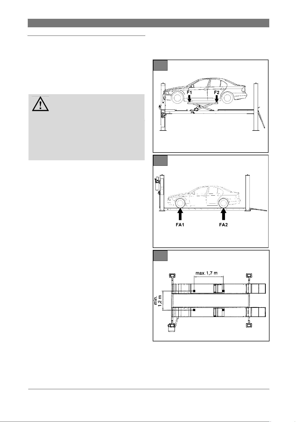
2.3 Permitted axle loads and weight
distribution
Before lifting the vehicle, you must ensure that the
weight distribution is correct.
When the weight distribution is correct (default position in direction of motion) the main load is located
at the front (e. g. engine).
Figure 1: SM40LT (with rolling jack)
Load capacity
● Main lift 4000 kg
● Rolling jack 3000 kg
● Length max. 1.7 m
● Width min. 1.2 m
Permitted weight distribution
● Main lift front max. 2/3:
F1 = max. 2670 kg
back max.1/3:
F2 = max. 1330 kg
● Rolling jack front max. 3/5:
F1: 1800 kg
back max.2/5:
F2: 1200 kg
Figure 2: SM40, AR43-5MB, SM55M51 VAS or
SM60
Load capacity
● AR43-5MB 4000 kg
● SM40, SM40-47 BMW 4000 kg
● SM55M51 VAS 5500 kg
● SM60 6000 kg
Permitted weight distribution
● SM40 front max. 2/3:
FA1 = max. 2670 kg
back max.1/3:
FA2 = max. 1330 kg
● SM60 front max. 2/3:
FA1 = max. 4000 kg
back max.1/3:
FA2 = max. 2000 kg
Figure 3: Approved distance between pick-up
points on rolling jacks
● SM60 front max. 2/3:
FA1 = max. 3667 kg
back max.1/3:
FA2 = max. 1833 kg
4

2. Safety
Rev.D 2013_03_en
2.4 Ban on unauthorized modifications
or alterations
Unauthorized modifications and alterations to the
post lift are not permitted for safety reasons.
The operating permit shall also be deemed null
and void.
The Declaration of Conformity also becomes null
and void.
2.5 Experts, competent persons
The post lift must be inspected after commissioning
and at regular intervals (after max. one year), as
well as after design modifications or repair of supporting parts. Inspections may be carried out by
the following people:
Certified expert
These are people who have specialist knowledge
in the field of lifts based on their professional training and experience.
Experts should be able to inspect lifts and make an
expert assessment thereof.
TÜV experts, specialist engineers from the manufacturer or self-employed specialist engineers can
be used for inspections.
Competent persons
These are people who have adequate knowledge
in the field of lifts based on their professional training and experience.
They are sufficiently familiar with health & safety
and accident prevention regulations as well as with
lift technology in order to be able to assess the occupational health & safety compliance of lifts.
2.6 Maintenance contractors, installation staff
Maintenance, servicing and installation work may
only be done by companies or specialists authorized
by the manufacturer.
These people trained in the field of lifts are competent persons, who are trained for maintenance as
well as repair work.
A competent person is a person who has adequate
knowledge based on his professional training and
experience and is also familiar with key regulations
so that he:
Can assess the work assigned to him,
Can recognize potential risks,
Can take actions required to eliminate the risk,
And has the required knowledge of repair and
fitment.
The specialist knowledge of a competent person
must enable him to be in a position to
Read and fully understand circuit diagrams,
Fully understand the context with particular re-
gard to any installed safety equipment.
Possess knowledge of the function and design of
system components.
Simple faults on the post lift may be rectified by
operating staff.
In the event of a more serious fault, contact an authorized maintenance contractor.
5

2. Safety
Rev. D 2013_03_en
i i i
2.7 Safety inspections by competent
persons
Safety inspections must be carried out to guarantee
the safety of lifts.
Safety inspections should be carried out in the following cases:
Before initial operation, after initial installation.
Use the form "Initial safety inspection before installation“.
After initial operation at regular intervals, but at
least once a year. Use the form "Regular Safety
Inspection“.
After any design modification to parts of the lift.
Use the form "Unscheduled Safety Inspection“.
The initial safety inspection as well as the
safety inspections must be carried out by a
competent person. We recommend that you
also perform maintenance in the course of the
inspection.
Unscheduled safety inspections and special
maintenance work are required in the event of
design modifications to the lift (fitting additional parts). The safety inspection must be
carried out by a competent person.
Use the form supplied in the Annex
containing lists for carrying out safety
inspections. Please use the relevant form and
staple it to the manual after completion.
6

3. The 4-Post Lift
Rev.D 2013_03_en
4
3. The 4-Post Lift
3.1 Overview of parts
Figure 4: Example of a 4-post lift
with rolling jack
1 Standard lift column
2 Lift column with control unit
3 Automatic ramp chock
4 Cross beams
5 Control unit
6 Compressed air unit with lubricator (Option)
7 Hydraulic unit with engine and tank (11 liters)
8 Base plate
9 Fixed runway
10 Drive-on ramp
11 Latch bar locking latch
12 Latch bar
13 Slip plate
14 Rolling jacks (SM40LT only)
15 Filler plate
16 Adjustable runway
17 Adjustable filler plate
T Nameplate
3.2 General workflow
After determining the vehicle data and aligning
the runways, the vehicle is driven onto the main
lift and secured against rolling.
The vehicle is raised to the desired height with
the main lift.
With optional rolling jack:
If a rolling jack is used, the manufacturerapproved pick-up points on the vehicle are selected and the matching supports are placed underneath. After adjusting the selector on the control unit and checking that the weight distribution
is correct, the vehicle is lifted by the rolling jack,
and the locking latch then locks. Only then can
work continue in the danger zone.
Main lifts and rolling jacks are fitted with a pneu-
matic locking mechanism.
If the lift lowers even slightly, for safety reasons it
automatically moves into the latch bar (locking
latch).
After completion of the work, the vehicle is low-
ered again to the ground and driven off.
7
3. The 4-Post Lift
Rev. D 2013_03_en
WARNING
Risk of injury in the danger zone of
the post lift in the event of incorrect
behavior.
Only remain in the danger area if you have
been trained and briefed and assigned to the
area.
Keep the work area clean.
Keep escape routes clear so that you can
leave the danger zone quickly and safely in
the event of an emergency.
WARNING
Safety mechanisms protect both
people and lift. They must not be
disabled!
Post lift danger zones are protected by safety
mechanisms.
Function and condition of the safety mecha-
nisms must be checked daily!
If safety mechanisms are triggered, the post
lift stops immediately.
If safety mechanisms are defective, the post
lift must be taken out of use immediately and
the main switch locked with a padlock. Any
further use must be prevented until the machine is fully repaired!
If the post lift is moved or taken out of use for
long periods, check the safety mechanisms
before re-commissioning and repair if necessary.
5
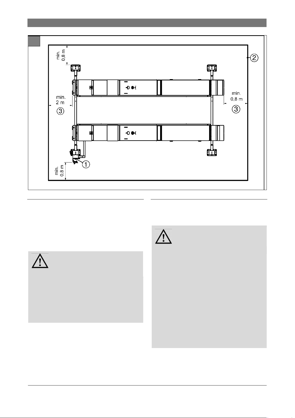
3.3 Work area, danger zones
Figure 5: Work area, danger zones
1 Control area
2 Work area and danger zone
3 Vehicle overhang
8
3.4 Safety mechanisms
See figures 6 ... 15
Rev.D 2013_03_en
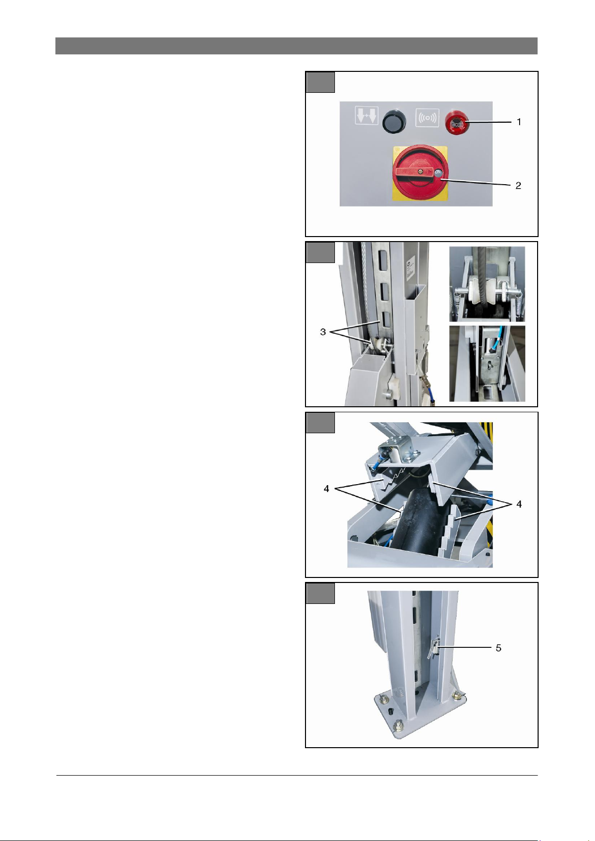
1 Buzzer
6
7
8
9
Acoustic alarm. Sounds:
● When lowering the main lift < 120 mm
(foot protection).
● When lowering the rolling jacks (hand and
finger protection).
● When troubleshooting (lifting/lowering using
the override switch, for height equalizing or
during emergency manual lowering).
2 Lockable main switch
"ON“ setting: Post lift ready for use.
"OFF“ setting: Post lift out of use. The mains
voltage is still present inside the control box.
Switching off (OFF) immediately stops any
movement of the post lift (= emergency stop).
3 Locking latch on each lift column
The locking mechanism consists of a latch bar
and roller with cam shaft. Latch bar with 100
mm locking latch notches.
If a fault occurs in the hydraulic system or if the
cable breaks or becomes slack, the brake
mechanism is activated. The cam is pressed
against the latch bar through a powerful spring
action. In addition a lock cam latches (via an
air piston) into the latch bar. All up or down
movements stop immediately. Any further lowering is prevented.
4 Locking latch on both rolling jacks
The locking mechanism consists of toothed
lock bars. On releasing the lift or lower button,
the upper bracket swings down. The lock bars
engage (ratchets).
5 Foot protection switch on the lift column
with control unit
Deactivates the lowering process at a lift height
of 120 mm (foot protection,
otherwise a crushing or shearing hazard exists).
You can only lower from this height by pressing
the "Down“ button and the
"Lower in danger zone“ button
(2-button safety switch).
3. The 4-Post Lift
Buzzer
9
3. The 4-Post Lift
Rev. D 2013_03_en
10
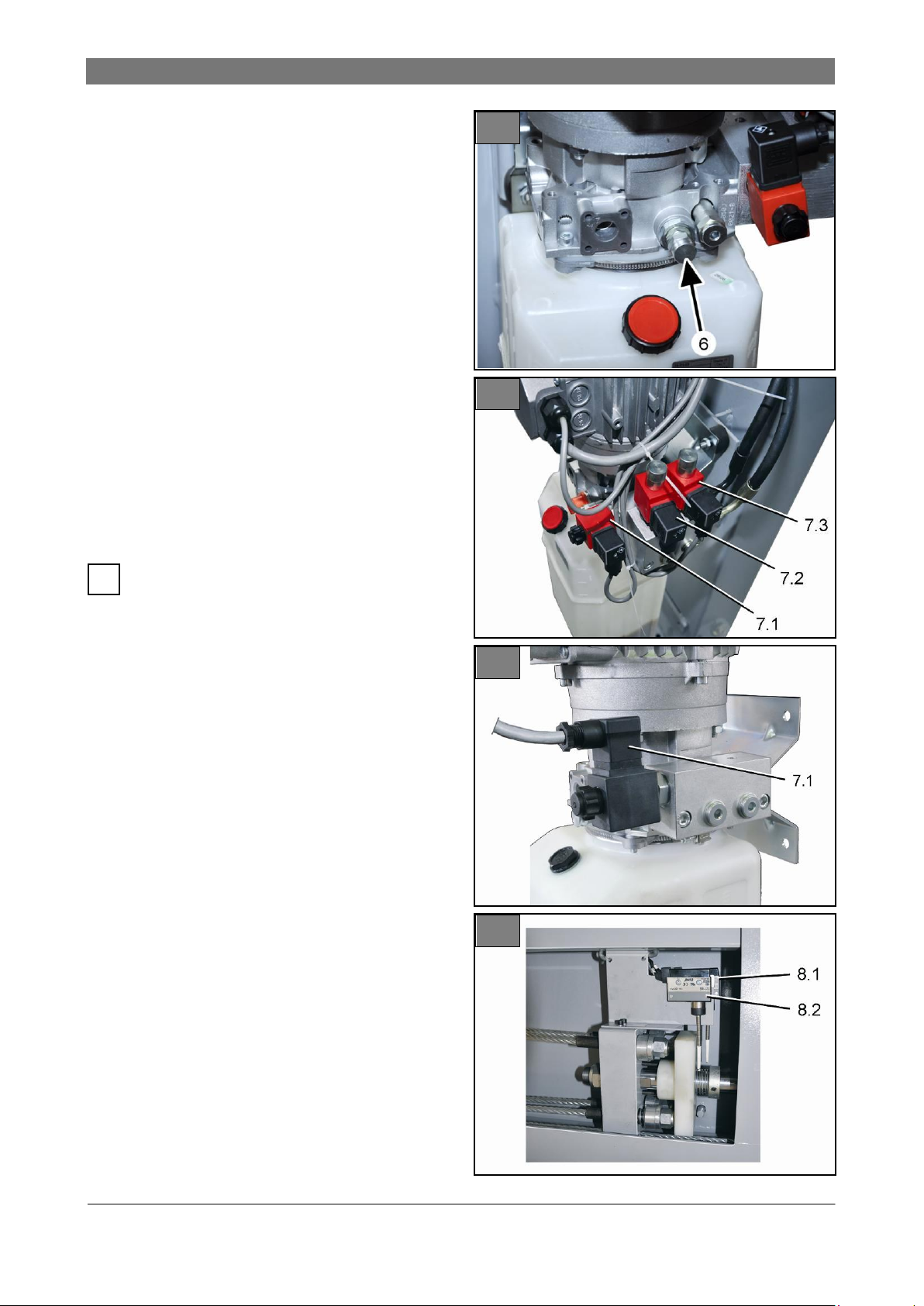
11
12
13
i
6 Pressure control valve
The pressure control valve (arrow) is factory
set to ca. 210 bar.
Prevents a sudden lowering of the lift in the
event of a leak in the hydraulic hose (lowering
speed = max. 1.5 x default speed).
7 Lowering valve (emergency release) and
emergency manual valves
● Pos. 7.1 Lowering valve for emergency re-
lease of the main lift or the rolling jack
(Fig. 12 = default configuration).
● Pos. 7.2 and 7.3: Emergency manual valve
for main lift and rolling jack. Fitted differently according to variant. Before use check assignment
to main lift and rolling jack.
During a power failure the valves close and
stop any movement.
8 Broken cable and slack cable switch
10
● Pos. 8.1: Broken cable switch:
This switch is activated if the cable is broken. All
movement of the post lift stops immediately. The
control buttons will not function. Consult a competent person for repair.
● Pos. 8.2: Slack cable switch:
This switch is activated when the cable is too
slack. All movement of the post lift stops immediately. The Down button will not function. The
Up button will however function in order that the
cable can be pulled tight again by raising the lift
slightly.

3. The 4-Post Lift
Rev.D 2013_03_en
14
15
9 Photo sensor for rolling jack runways:
Guards against height differences of >
50 mm between the runways
Stops the lowering or lifting process if the difference in height between the two runways is
greater than 50 mm.
10 Rolling jack warning stripes (yellow-black)
Warning stripes on the rolling jack scissors.
Hand and finger protection warning, otherwise
a crushing and shearing hazard may exist during the lifting or lowering process.
11
3. The 4-Post Lift
Rev. D 2013_03_en
16
i
i
3.5 Control unit
All movement of the lift stops immediately
when you release a pressed button.
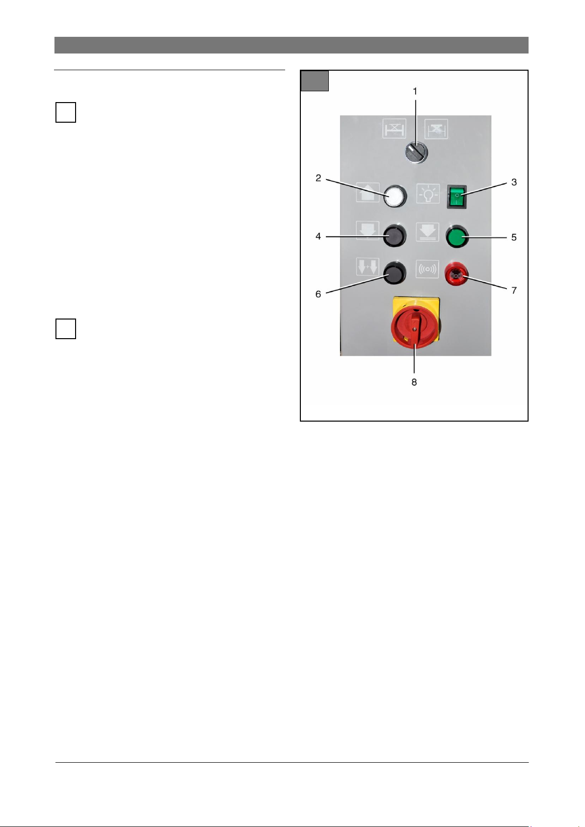
Figure 16: Control unit in the lift column
1 Selector, only for SM40LT variant with rolling
jack:
● Left setting: Main lift active
● Right setting: Rolling jack active
2 UP button
For main lifts or rolling jacks.
Functions only if the button is pressed.
Post lift /rolling jack runways move up.
3 On/off switch for optional lighting.
4 DOWN button
●For main lifts or rolling jacks.
Functions only if the button is pressed.
The main lift or rolling jack runways move up
for around 2 seconds to release themselves
from the locking latches.
Runways move down until the automatic shut-off
is activated 120 mm above the ground
(foot protection, otherwise this may present a
crushing and shearing hazard). The lowering
process stops.
5 LOCK button
●For main lifts or rolling jacks.
Functions only if the button is pressed.
● Main lift: Locks the cross beams in the latch
bars of the four lift columns. Keep button
pressed until all cross beams lock securely into
the latch bars.
● Rolling jack: Lowers both runways onto the
toothed lock bars (ratchets).
Keep button pressed until both runways lock
securely into the latch bars.
6 DOWN button in the danger zone below 120
mm
● For main lifts or rolling jacks.
Only functions after the 120 mm automatic
shut-off has reacted to DOWN (4). The runways can then be lowered completely if both
buttons (5) and (6) are pressed at the same
time. A buzzer sounds throughout the entire
lowering process.
7 Buzzer
Acoustic alarm. Sounds:
● When the main lift is being lowered < 120
mm (Foot protection)
● When the rolling jack is being lowered (hand
and finger protection).
● When troubleshooting (lifting/lowering using
the override switch, for height equalizing or
during emergency manual lowering).
8 Lockable main switch
"ON“ setting: Post lift ready for use.
"OFF“ setting: Post lift out of use. The mains
voltage is still present inside the control box.
Switching off (OFF) immediately stops any
movement of the post lift (= emergency stop)..
12
4. Operation
Rev.D 2013_03_en
DANGER
Risk of injury when lowering the
load onto objects below the lift or
the vehicle. Vehicle may topple
over.
Before lowering, you must remove all objects
from underneath the lift. This applies in particular to chassis stands and auxiliary jacks.
Always monitor the lift and vehicle carefully
when lifting or lowering.
DANGER
Risk of fatal injury if load is incorrectly distributed on both rolling
jacks. Vehicle may topple over.
Check that axle loads and weight distribution
are correct in accordance with Chapter 1.3.
Secure the load with adequately sized chassis
stands.
DANGER
Risk of fatal injury in the event of
malfunction or damaged parts.
Shut down post lift. To do so, set the main
switch to "OFF“and lock it with a padlock.
Consult a competent person.
i
i
4. Operation
4.1 Emergency stop
1. To perform an emergency stop, set the main
switch to OFF ("OFF“setting). The main lift or
the rolling jack stops immediately.
4.2 Switch the machine on
1. Switch on the power supply with the main switch
("ON“setting).
2. Check the operational status of the main lift and
the rolling jack.
3. Check the functionality of the control buttons.
4. Check the functionality of the buzzer. To do so
raise the runways slightly from the bottom position and lower again. A buzzer must sound
when lowering.
5. Lower the main lift (including drive-on ramps)
rolling jack completely.
6. Keep work area and runways clean (no objects
lying around, no grease, no oil).
When working with the post lift, make sure
you follow the instructions listed in Chapter 2. Safety.
4.3 Determine the vehicle data
1. Determine the weight details and the vehicle
height (see vehicle license).
Check the vehicle center of gravity, check the
load and body. Check the permitted weight
distribution on the lift.
2. Compare details with the nominal data of the lift.
3. Determine the approved pick-up points accord-
ing to the manufacturers specifications.
4. If the vehicle data is not available, ask the su-
pervisor.
13
4. Operation
Rev. D 2013_03_en
17
DANGER
Risk of injury in the post lift zone.
Do not put people at risk when the lift or rolling
jack moves.
Always monitor the danger zones when lifting
or lowering.
No-one must stand in the traffic zone of the lift.
WARNING
Danger of crushing and shearing of
limbs (foot, toe, finger etc.). Possible uncontrolled movement when
lowering in the danger zone (below
the runways, cross beams) or when
moving the rolling jack scissors.
No parts of the body below the runways,cross
beams, or in the rolling jack scissors zone.
A buzzer sounds during the lowering process
in the danger zone < 120 mm.
Do not place objects below the lift or the rolling
jack.
ATTENTION
Damage to high vehicles when
LIFTING and LOWERING. Vehicles
which are too high may collide with
the ceiling.
Even when LOWERING, the main lift or rolling
jack briefly moves up (out of the latches).
Monitor the process constantly.
Make sure that the vehicle does not collide
with the ceiling.
i
i
4.4 Driving on
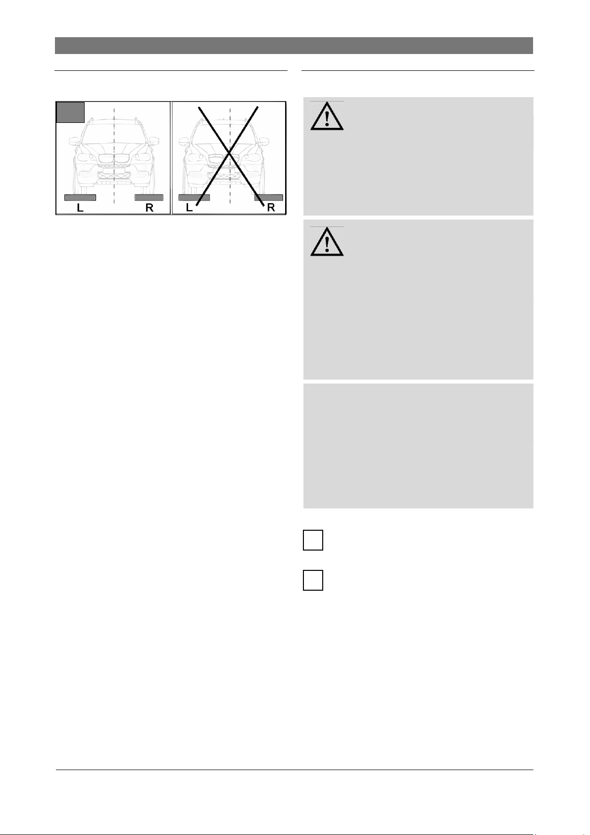
1. If required, set the adjustable runways (Fig. 17,
Pos R) according to the width of the vehicle. To
move them, loosen 2 runway bolts on each of
the two cross beams, move the runways in parallel, then tighten the bolts again.
2. Drive the vehicle onto the runways centered on
both sides (have someone guide you on). Make
sure that the wheels do not hang over the edges
of the runways.
3. Apply the vehicle handbrake, get out, and close
all vehicle doors.
4. Secure the vehicle with chocks against rolling.
4.5 Lifting/lowering
5. Place supports or pads at the 4 approved pick-
up points. Only use supports or pads approved
by the manufacturer. These must be correctly
and stably positioned.
6. Take safety measures to ensure that neither
people nor loads can collapse or fall and loads
cannot slip. Make sure the weight distribution is
correct.
The lifting or lowering process must be
carried out uniformly so that the load does not
change position.
If the vehicle does not remain stable, end all
movement immediately.
Then turn the main switch to "OFF“ and lock
it. The vehicle must now be lowered by an authorized competent person.
14
 Loading...