

SM30/RFL25
SM30 Capacity 30,000 lbs. (15,000 lbs. per axle)
140” Minimum Wheelbase
I
N
N
S
S
T
T
A
A
L
L
I
RFL25 Capacity 25,000 lbs. (12,500 lbs. per axle)
L
L
A
A
T
T
I
O
O
N
N
I
N
N
S
S
I
I
© July 2018 by Vehicle Service Group. CO10598.0 IN20490
Rev. J 7/24/2018
LP20460
T
T
R
R
U
U
C
C
T
T
I
O
O
N
N
S
S
I
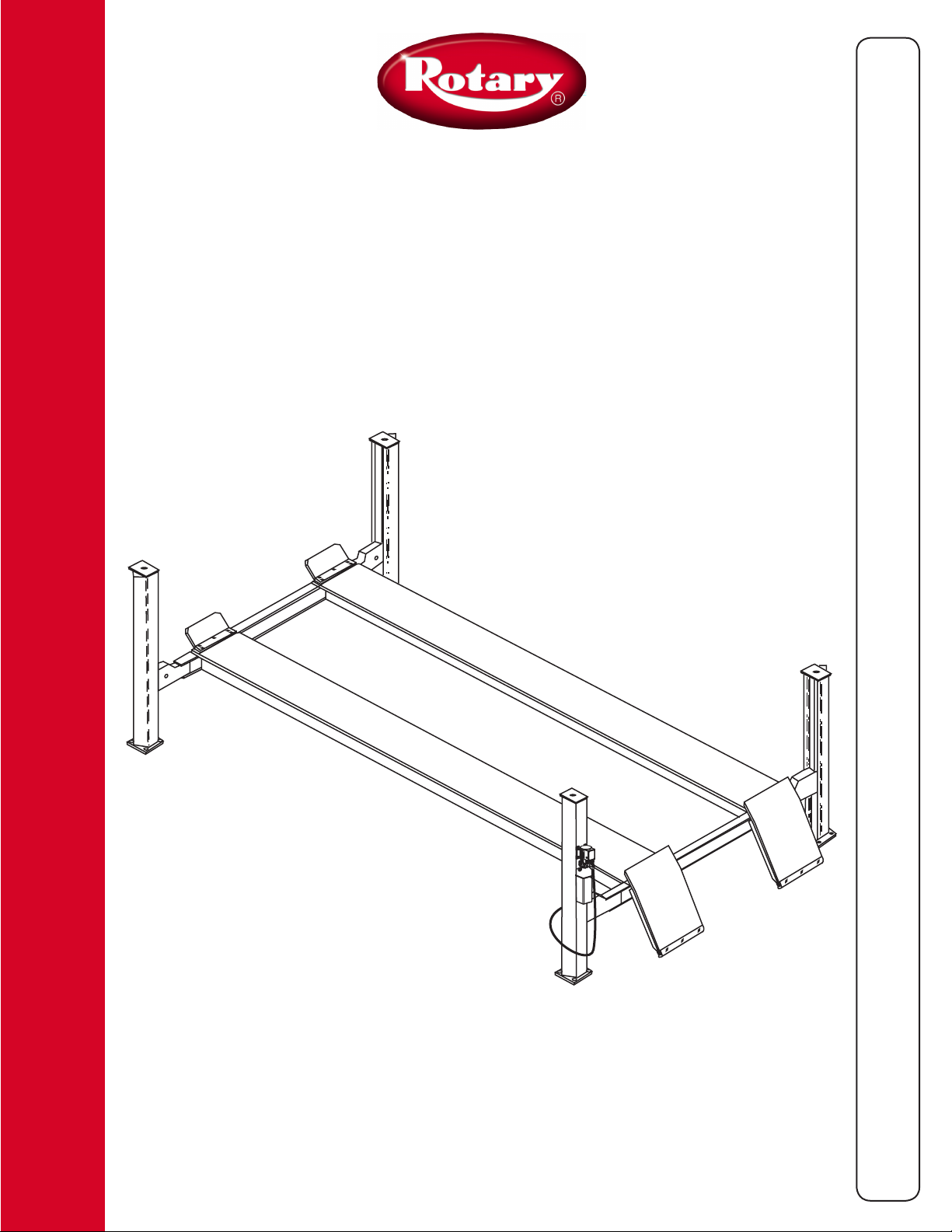
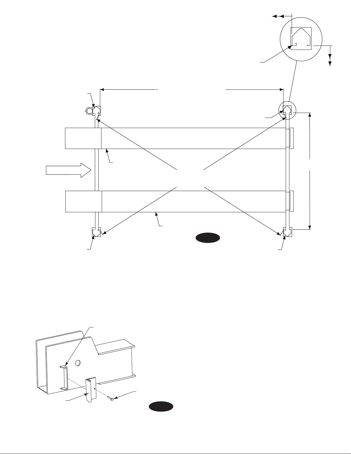
Required Clearances
WARNING
Estimation Shim Requirements
Dimension at highest position minus other
APPROACH
Rear Clearance
Rear Clearance (Min. 5'-6" for SM30's, 8'-6" for
RFL25's) = rear overhang of longest vehicle + required
work space
Fig. 1
Read and understand Installation Instructions completely
before starting with lift installation.
1. Lift Location: Use architects plan when available to locate lift.
Fig. 1 shows dimensions of a typical bay layout. For power
unit at right front, rotate lift 180°, leaving ramp/chocks and
wheel stops in original position. Lift floor area should be
level.
DO NOT install on asphalt or other similar
unstable surfaces. Columns are supported only by anchors in
floor.
Note: If runway extensions are used, an additional 3’–0” of
clearance must be added to end with extensions.
Left
Runway
Right
Runway
C
L
8'–0" Min. To
Nearest
Obstruction
8'–0" Min. To
Nearest
Obstruction
Front Clearance
Front Clearance = front overhang of
longest vehicle + required work space
2. Ceiling or overhead clearance must be 80” plus height
of tallest vehicle.
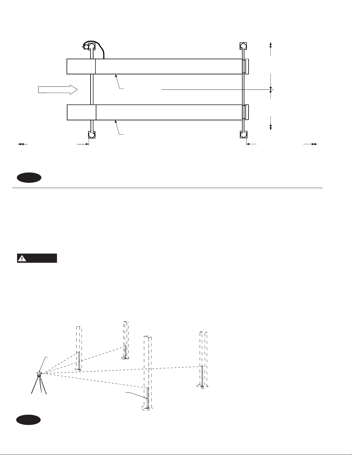
3. Estimating Column Shim requirements:
In the following section, the terms “highest” and
“lowest” refer to elevation of floor.
A. Mark locations where lift columns will be
positioned in bay.
B. Place target at column positions and record
readings, Fig. 2.
C. Find the highest of the four (4) locations. Find the
difference between the reading at each of the
remaining three (3) columns and the highest
reading.
D. The difference is the estimated amount of shim
thickness needed at each column.
FRONTREAR
Fig. 2
Transit
Target
position = shim thickness required
2
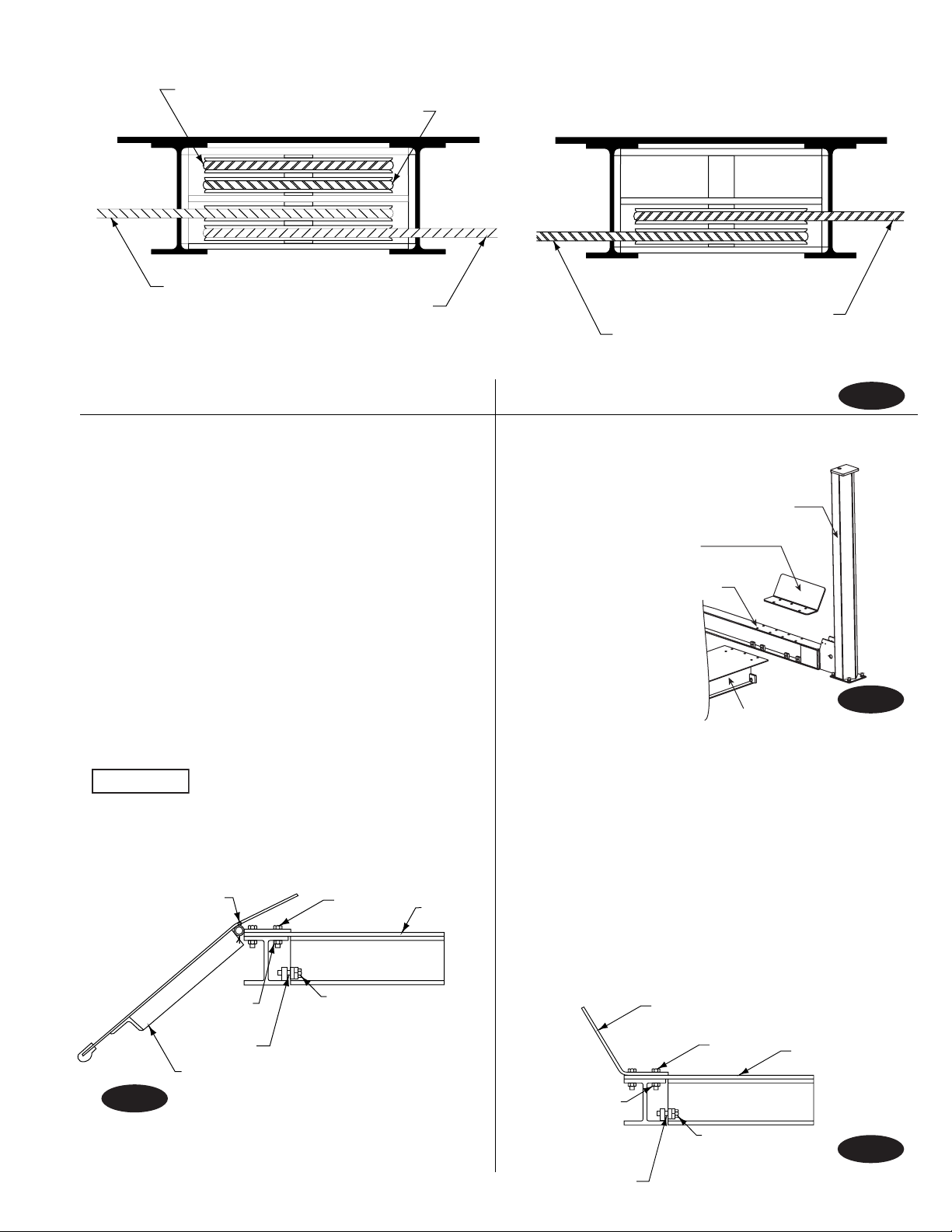
Cable Seating in Sheave Grooves
Fron
(V
Right Rear
IMPORTAN T
Feed Cable Ends Through Yoke End
Ramp/Chock
Ramp/chock
Wheel Stop
Flange
Nuts
Cable (#4)
Left Rear
Cable (#3)
Right Front
Cable (#2)
Left Front
Cable (#1)
t
iewed from front)
E. Maximum shim thickness of 2” is possible by using shims
and anchors provided with lift. If more shimming is required,
consult factory for different shim package including longer
anchor bolts.
4. Runway and Yoke Assembly:
A. Determine direction of approach in bay.
B. Position left runway in bay with hydraulic cylinder hose
connection to rear of bay. Cables and sheaves are preassembled in runway. Runway needs to be up off floor so
shipping restraints can be removed from cable ends, air
and hydraulic lines, and cylinder rod. Pull cables, air and
fluid lines out for assembly. Make sure cables are in proper
sheave grooves, Fig. 3.
C. Position front and rear yokes at respective ends of
runway, Fig. 1. Feed cable ends through yoke end, Fig. 4. Do
not assemble sheaves in yoke ends at this time.
Be sure cables are not crossed inside yoke.
Cotter Pin Should Be
On Outside Of
Runway
Bolts
Runway
Right Rear
Left Rear
Cable (#4)
Cable
Rear
(Viewed from rear)
(#3)
Fig. 3
Right Front Column
Permanent
Wheel Stop
Alignment Holes
For Runway Adjustment
Right Runway
Fig. 4
D. Lay right runway in place on yoke. Slide right runway toward
outside of lift until holes in yoke and runway line up, Fig. 4.
Hold runway in place and bolt on ramp/chock and wheel
stops to runway using ten 5/8” x 2 1/2” bolts and flange nuts.
Square up yokes with runways using four 3/4”-10NC x 2” lg.
bolts, 3/4” flat washers, 3/4” lock washers, and shims. Ramp/
chocks go on rear, Fig. 5. and Fig. 6. Repeat for left runway.
E. Insert each end of the left runway’s 1/4” air line into the Tee’s
connecting the locking latch air cylinders in each yoke, Fig. 7.
Fig. 5
Flange
Nuts
Shim
3/4" x 2" lg. Bolts
3/4" Lock Washers
3/4" Flat Washers
Permanent
Wheel Stop
Bolts
3/4" x 2" lg. Bolts
3/4" Lock Washers
3
Shim
3/4" Flat Washers
Runway
Fig. 6
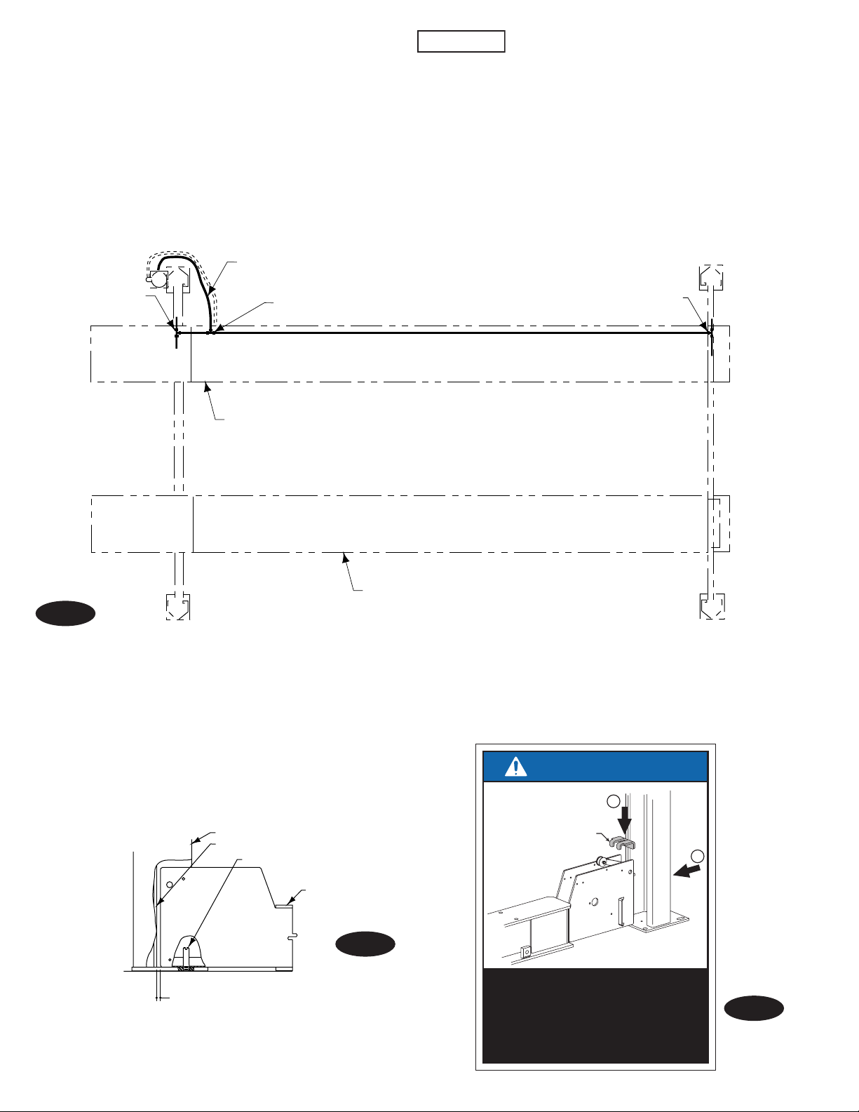
5. Columns:
IMPORTAN T
Note: Columns are not interchangeable. They must be set at their
respective corner of the lift. Column double return bend is always
to inside of lift, Fig. 9. Place the power unit column at the left
rear corner of the lift. The point where the hydraulic hose passes
through side of left runway should be visible from this corner.
Insert alignment stud through hole in yoke end and thread into
base plate of column, Fig. 8. Repeat for other columns.
The yoke/column alignment studs MUST be used
for proper centering of columns to yokes, Fig. 8. A gap of
5/16” must be maintained between column and yoke.
See step 6 B. Note: It may be necessary to remove Plastic Slider
from Column Stop on yoke end, Fig. 10, before aligning yoke
in column. After yoke is in column, reinstall Plastic Slider and
secure with 5/16” button head screw.
Fig. 7
Tee
Air Line To
Lift
Tee
Left Runway
Air Line in Runway
Tee
Right
Runway
Alignment Stud
Column
Latch Bar
Alignment Stud
Yoke Assembly
Fig. 8
5
/
" REF. Between Yoke End and Latch Bar
16
IMPORTANT
1
Ears Of
Spacer
2
Use Yoke Spacer As Shown To
Maintain 5/16" Of Gap From End
Of Yoke To Front Of Latch Bar.
Be Sure To Remove Spacer
After Installation.
4
Fig. 8a
Power Unit Column
Tapping
Plastic Slider
Plastic Slider
Check Lift Dimensions
Double Return Bend always
to the Inside of Lift.
RFL25 ....... 177 1/8" Ref.
SM30S ........ 249 1/8" Ref.
SM30L ........ 285 1/8" Ref.
SM30EL......321 1/8" Ref.
Between Columns
Width and length measurements are made from column
sides, NOT column base plate. Diagonals are measured from
inside corner of column.
Left Front
Column
APPROACH
Right Rear Column
Left Runway
Column Stop
Diagonals
Within
Right Runway
1
133 1/4" Ref.
/ 4 "
Fig. 9
Right Front Column
1
/4"
Screw
Fig. 10
5
 Loading...