

Rotary SL235MP, SL235BR, SL230RA-PE, SL235S3, SL235BR-RA Installation Instructions Manual
...
Installation Instructions ROTARY inground lifts SL230/SL235/SL250 • Release: 11/2013 • Page 1
SL230 / SL235 / SL250
Capacity: 3000, 3500 resp. 5000 kg
Models
SL235MP
SL235S3
SL235RA
SL235BR
SL230RA-PE
SL235BR-RA
SL250RA
SL250BR-RA
SL235DOP
These instructions contain general data. Any deviation from customers prints or specifications should be clarified before
proceeding with lift installation.
Important: Check the steel cassette for damage before installation. Do not install a damaged cassette.
Contact Rotary Lift customer service. If the lift has a chance to be exposed to the elements, protect the lift.
© November 2013 by BlitzRotary GmbH. InstInstr N1.8
Rev. 28.11.2013
I
N
S
T
A
L
L
A
T
I
O
N
I
N
S
T
R
U
C
T
I
O
N
S
Installation Instructions ROTARY inground lifts SL230/SL235/SL250 • Release: 11/2013 • Page 2
IMPORTANT
Failure to comply will void warranty!
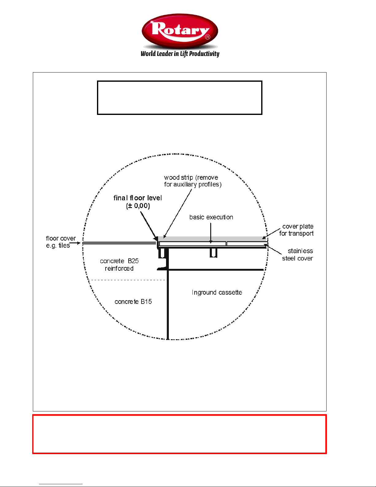
Owner: Your installer is responsible for the correct installation
level. The round-running level for the final floor level is the
vertical tile frame of the cassette and NOT the temporary wood
cover. This wood cover is only for protection during transport
and installation.
ATTENTION!
The protection covering (wooden cover) must not be removed until the commissioning by a Rotary-
certified expert takes place!

Installation Instructions ROTARY inground lifts SL230/SL235/SL250 • Release: 11/2013 • Page 3
Content
1 General remarks ............................................................................ 3
2 Installation of the inground cassette .............................................. 5
3 Installation of the lifting cylinders ................................................... 7
4 Installation of the power unit .......................................................... 9
5 Installation of the control .............................................................. 10
6 Bleeding and adjustment of the cylinders .................................... 14
7 Installation of the supports ........................................................... 16
8 Test run and handing over ........................................................... 20
9 Appendix: Error codes of control .................................................. 22
10 Appendix: DIP-Switches .............................................................. 24
1. General remarks
1.1 Introduction
The lifting device delivered together with this assembly instructions is according to the tested model. Therefore it
would not be necessary for an approval before first use. However, there is no way to deliver the lifting platform
´ready to use´. Therefore before the first putting in operation must be an examination by an expert. The correct
working conditions include the faultless function of all security equipment. This installation instruction is for experts
in the sense of the European Community (EG guideline 89/392/EWG, Appendix 1, including the changes of
20.06.1991, 91/368/EWG). Experts are persons, who have expierience, formation and know-how on the field of
lifting platforms and with the working security guidelines of the specific country. They have to know the accident
avoiding guidelines and common technics to insure the safe working condition of lifting platforms.
1.2 Safety guidelines
During the use of the lifting platform, the regulations and rules of accident prevention are to be considered
fundamentally.
Only properly trained and authorized operators shall be allowed to operate the lift.
Unauthorized changes and modifications to the lifting platform relieve ROTARY from any liability for any damages
and injuries that might result therefrom.
Especially making inoperative or removal of the safety devices means a grave violation of the health and safety at
work regulations.
Burdens may only be included in accordance with the agreed use.
The maximum capacity must not be exceeded (pay attention to any additional load).
Installation Instructions ROTARY inground lifts SL230/SL235/SL250 • Release: 11/2013 • Page 4
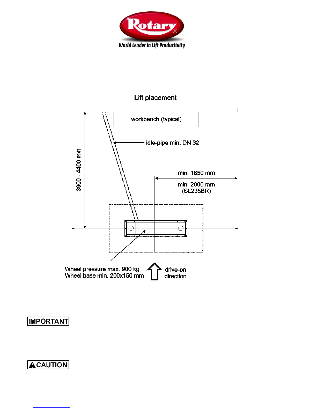
1.3 Installation site
The production-line lift is not equipped for the assembly in blast endangered rooms. The final placement has to be
taken from the architect´s plan. We recommend the workplace dimensions described in fig. 1.
Fig. 1
1.3 Electrical connection
Electrical connection and wiring is only allowed to be performed by an electro-technician with
consideration of the VDE guidelines and the guidelines of the local energy supplier. For the electrical connection
must be power supply with 3~/N+PE 400 volts, 50 Hz at installation site. The electrical fuse must be of quality T16
Amperes according to the German guideline VDE 0100. Feeding the supply occurs into the control box.
If there are only 3~/N+PE 230 volts available, the lift must be especially adapted at circuit board and motor
clamping. These adaptations are NOT included in this manual. You have to ask separately for these requirements!
The power supply connection may only be supplied by an electro-technician. In this case a
check of the protective earth with 10 Ampere and a high voltage check with 1000 Volt has to be carried out. This
check has to be remarked in the testing book owners manual.
Installation Instructions ROTARY inground lifts SL230/SL235/SL250 • Release: 11/2013 • Page 5
2. Installation of the inground cassette
2.1 Foundation plan
Installation, adjustment and concrete of the in-ground cassette is described in detail in the
respective foundation plan. Ensure before installation that you have the valid foundation plan.
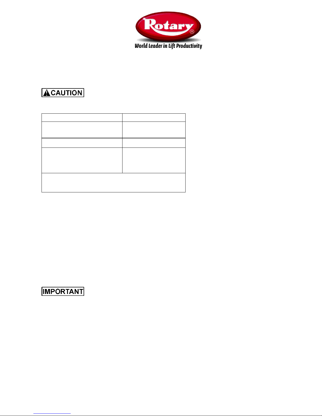
Model
Foundation plan
SL235MP, SL235RA,
SL250RA, SL235S3,
FP1335
SL235DOP
FP1335*
SL230RA-PE
SL235BR, SL235BR-RA
SL250BR-RA
FP2285
* If the platform lifts have to be installed inground or inground
together with floor level compensation you have to use different
foundation plans!
Table 1: Foundation plans
2.2 Lifting into the cavity
To move the inground cassette into the cavity use either 2 eye screws or the auxiliary profiles together with a belt.
The eye screws have to be fixed diagonally through wood cover and basic executions into the screw threads of the
cassette. Use the inner threads of the basic executions (fig. 2, ´X´). In this case you can fix the auxiliary profiles at
the outside later on. Now lift the inground cassette into the cavity using a suitable lifting device.
2.3 Inground installation options
In general there are two main possibilities for inground installation (fig. 1 and 2). In principle it makes no difference
if the cassette is ´empty´ or ´pre-assembled´ inclusice the complete hydraulic system inside (standard delivery).
Do not forget the vacant pipe from the inground cassette towards the site of the control (see
foundation plan). The connection between vacant pipe and the cassette must be water-tight! Don´t cut the vacant
pipe at the wall not at floor level to avoid penetration of water!

Installation Instructions ROTARY inground lifts SL230/SL235/SL250 • Release: 11/2013 • Page 6
Fig. 2 Installation in existing floor
Fig. 3 Installation without existing floor
Installation Instructions ROTARY inground lifts SL230/SL235/SL250 • Release: 11/2013 • Page 7
3. Installation of the lifting cylinders
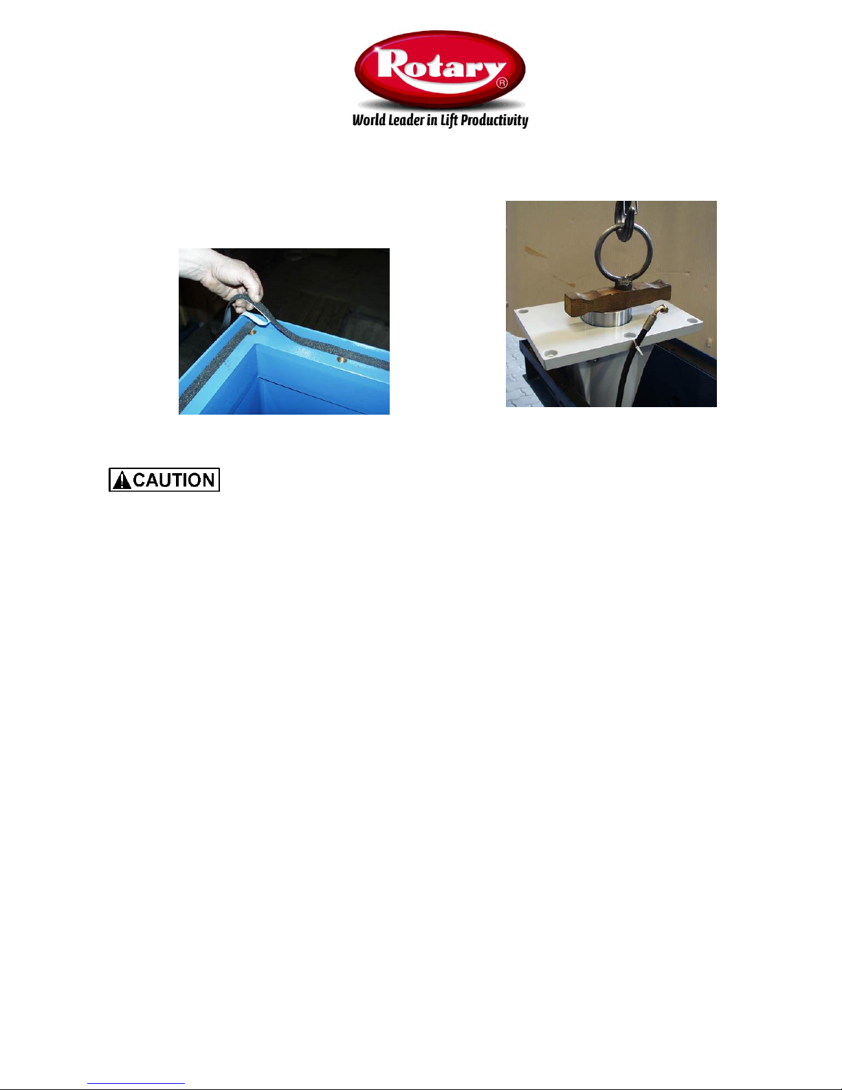
Fig. 4 Fixation of cellular polyethylene Fig. 5 Lifting with an eye screw
If the in-ground cassette is not delivered "empty" for pre-installation, but "pre-assembled"
inclusive cylinders, cross bar, hydraulic pump and potentiometer mechanism (standard), you don’t have to perform
the work in chapter 3 and 4. In this case please continue directly with chapter 5!
3.1 Check before start
Please check before installation the correct and level building in of the lift box (+/-0 up to +3 mm to final floor level).
The position of the control box must be out of the dangerous area and the lift must be observable at least at two
sides.
3.2 Preparation of the empty cassette
Take off the wooden cover from the installation cassette and remove the cross connection using an angle grinder.
Check the room inside for cleanness, if necessary remove dirt and water. The frame of the installation cassette has
to be clean so that the basic guides and the cover lies plane.
First fix the self-adhesive cellular polyethylen on the cassettes´ frame (only necessary if the cassette was delivered
´empty´).
Before putting in the cylinder units into the installation cassette the hydraulic hoses at the cylinders have to be retightened. The free end for the connection at the motor pump has to be fastened at the basic guides using cable
ties.

Installation Instructions ROTARY inground lifts SL230/SL235/SL250 • Release: 11/2013 • Page 8
3.3 Installation of the hydraulic cylinders
Tighten the hydraulic hoses at the cylinder before mounting the hydraulic cylinders and fix the free end for the
connection to the hydraulic unit temporarily on the basic executions with a cable tie as far as this hasn’t been done
already ex-works. Now install the hydraulic cylinders on the right and left side with the welded synchronization lever
into the installation cassette. For best results use an eye screw M20 (models up to 3500 kg capacity) or M24
(models with capacity 5000 kg), which will be screwed into the cylinder (fig. 5). These screws are not contained in
the scope of delivery.
The piston rod has not to be fixed against falling out during handling because of the depression. It may go out only
about 15 cm.
Fix the eye screw not on the basic execution!.
The hydraulic cylinder with the screwed on proximity switches prepared ex-works is to be
installed at the right side in driving direction. After the lifting in screw in the socket head screw for fixation of the
basic executions and tighten it lightly for the moment.
Installation Instructions ROTARY inground lifts SL230/SL235/SL250 • Release: 11/2013 • Page 9
4. Installation of the power unit
4.1 Delivery situation
If the inground cassette was not delivered ´empty´, the hydraulic pump is completely pre-assembled inside the
cassette inclusive fixation support, cables and tubes and hydraulic oil. The connectors for the hydraulic hoses are
covered with a screw cap during transport. Furthermore, the pre-filled hydraulic pump is covered with a srew cap
during transport to protect from running out the oil.
4.2 Fixation of the hydraulic pump
Hang up the hydraulic unit into the side thread mounts of the in-ground cassette and attach with the screws (M10
with fixation teeth) contained in scope of delivery. Connect hydraulics hoses to the connections A and B of the
hydraulic pump according hydraulic plan HP20410(standard power unit 20410 for all models (fig. 6).
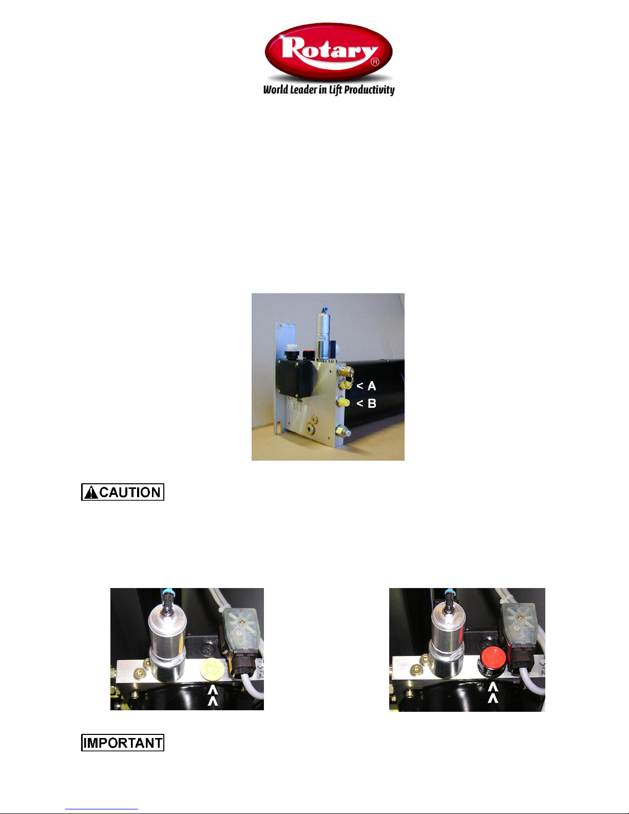
Fig. 6 Connections at power unit 20410
In principal it doesn´t matter which hose is connected to which connection. But the hydraulic
hoses have to hang free between synchronizing mechanism and outer wall of the installation cassette.
4.3 Remove transportation locking
Remove screw cap (fig. 7; transportation locking) at the pump at the oil filler pipe and screw in enclosed ventilation
screw (fig. 8). The ventilation screw is contained in scope of delivery inside the control box.
Fig. 7: Screw cap (yellow) only for transport Fig. 8: Bleeder screw (red) for use
It is not allowed to use the lift with transportation locking of the pump, because this can destroy
the pump!
 Loading...