

Rotary SL212i 400 Series, SL29i 400 Series Operation & Maintenance Manual

SL29i/SL212i
(400 Series)
SL29i Capacity 9,000 lbs.
SL212i Capacity 12,000 lbs.
O
O
P
P
E
E
R
R
A
A
T
T
I
I
O
O
N
N
&
&
M
M
Table Of Contents
Introduction ........................................................................ 2
Owner/Employer Responsibilities .................................... 3
Safety Instructions ............................................................. 4
Operating Instructions ...................................................... 6
Maintenance Instructions.................................................. 10
Trouble Shooting ................................................................ 11
Manual Lowering of Lift..................................................... 14
Date and Time Setting ....................................................... 16
Timer and Alarm Setting .................................................... 17
Rotary Contact Information ............................................... 18
Change Language .............................................................. 19
A
A
I
I
N
N
T
T
E
E
N
N
A
A
N
N
C
C
E
E
M
M
A
A
N
N
U
U
Installer: Please return this booklet to literature package and give to lift owner/operator.
© January 2003 by Rotary Lift.
LP20089
OM20120
Rev. B 01/28/03
A
A
L
L
INTRODUCTION
The Rotary inbay technology lift represents a
technological advancement that brings the power of
information right into the service bay.
• Bay management tools include owner and operator
instructions, maintenance reminders, troubleshooting
tips, date and time display and illustrated pickup
points.
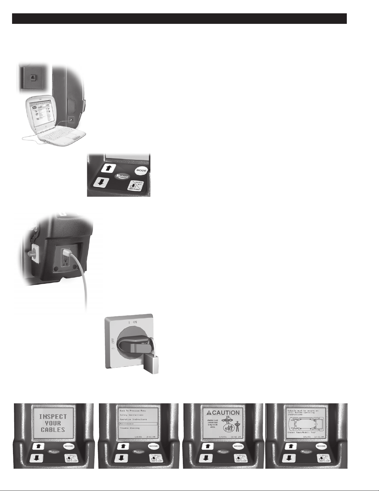
• Convenience features include integrated air and
GFCI-protected electric connections at the control
panel, as well as a telephone/data port on the console.
• Ergonomics are improved by the use of soft touch
membrane controls for single-hand lift operation.
• On-board training is accessible at any time with the
touch of a button.
• Advanced safety include an OSHA compliant
lockable disconnect switch.
• Audible alarm, with an on/off option, signals when
the lowering button has been activated.
• Low voltage operation (24v) in the event of a shorted
or grounded circuit reduces the risk of shock.
• Liquid Detection System in the containment housing
and on-screen alerts help prevent accumulation of
water.
2
C
A
U
T
IO
?
?
Lift to be used
by trained operator
only.
SAFETY
INSTRUCTIONS
OWNER/EMPLOYER RESPONSIBILITIES
The Owner/Employer:
• Shall ensure that lift operators are qualified and that they are trained in the safe
use and operation of the lift using the manufacturer’s operating instructions;
ALI/SM 93-1, ALI Lifting it Right safety manual; ALI/ST-90 ALI Safety Tips
N
?
©
card; ANSI/ALI ALOIM-2000, American National Standard for Automotive
Lifts-Safety Requirements for Operation, Inspection and Maintenance; ALI/WL
Series, ALI Uniform Warning Label Decals/Placards; and in the case of frame
engaging lifts, ALI/LP-GUIDE, Vehicle Lifting Points/Quick Reference Guide
for Frame Engaging Lifts.
• Shall establish procedures to periodically inspect the lift in accordance with the
lift manufacturer’s instructions or ANSI/ALI ALOIM-2000, American National
Standard for Automotive Lifts-Safety Requirements for Operation, Inspection
and Maintenance; and The Employer Shall ensure that lift inspectors are quali-
fied and that they are adequately trained in the inspection of the lift.
Proper maintenance
and inspection
is necessary
for safe operation.
• Shall establish procedures to periodically maintain the lift in accordance with
the lift manufacturer’s instructions or ANSI/ALI ALOIM-1994, American
National Standard for Automotive Lifts-Safety Requirements for Operation,
Inspection and Maintenance; and The Employer Shall ensure that lift mainte-
©
nance personnel are qualified and that they are adequately trained in the maintenance of the lift.
• Shall maintain the periodic inspection and maintenance records recommended
by the manufacturer or ANSI/ALI ALOIM-2000, American National Standard
for Automotive Lifts-Safety Requirements for Operation, Inspection and Maintenance.
• Shall display the lift manufacturer’s operating instructions; ALI/SM 93-1, ALI
Lifting it Right safety manual; ALI/ST-90 ALI Safety Tips card; ANSI/ALI
ALOIM-1994, American National Standard for Automotive Lifts-Safety Requirements for Operation, Inspection and Maintenance; and in the case of
frame engaging lifts, ALI/LP-GUIDE, Vehicle Lifting Points/Quick Reference
Guide for Frame Engaging Lifts; in a conspicuous location in the lift area
convenient to the operator.
• Shall provide necessary lockout/tagout means for energy sources per ANSI
Z244.1-1982 (R1993), Safety Requirements for the Lockout/Tagout of Energy
Sources, before beginning any lift repairs.
• Shall not modify the lift in any manner without the prior written consent of the
manufacturer.
3
TAB CAN BE PULLED
OUT AND LOCKED
IN THE OFF POSITION
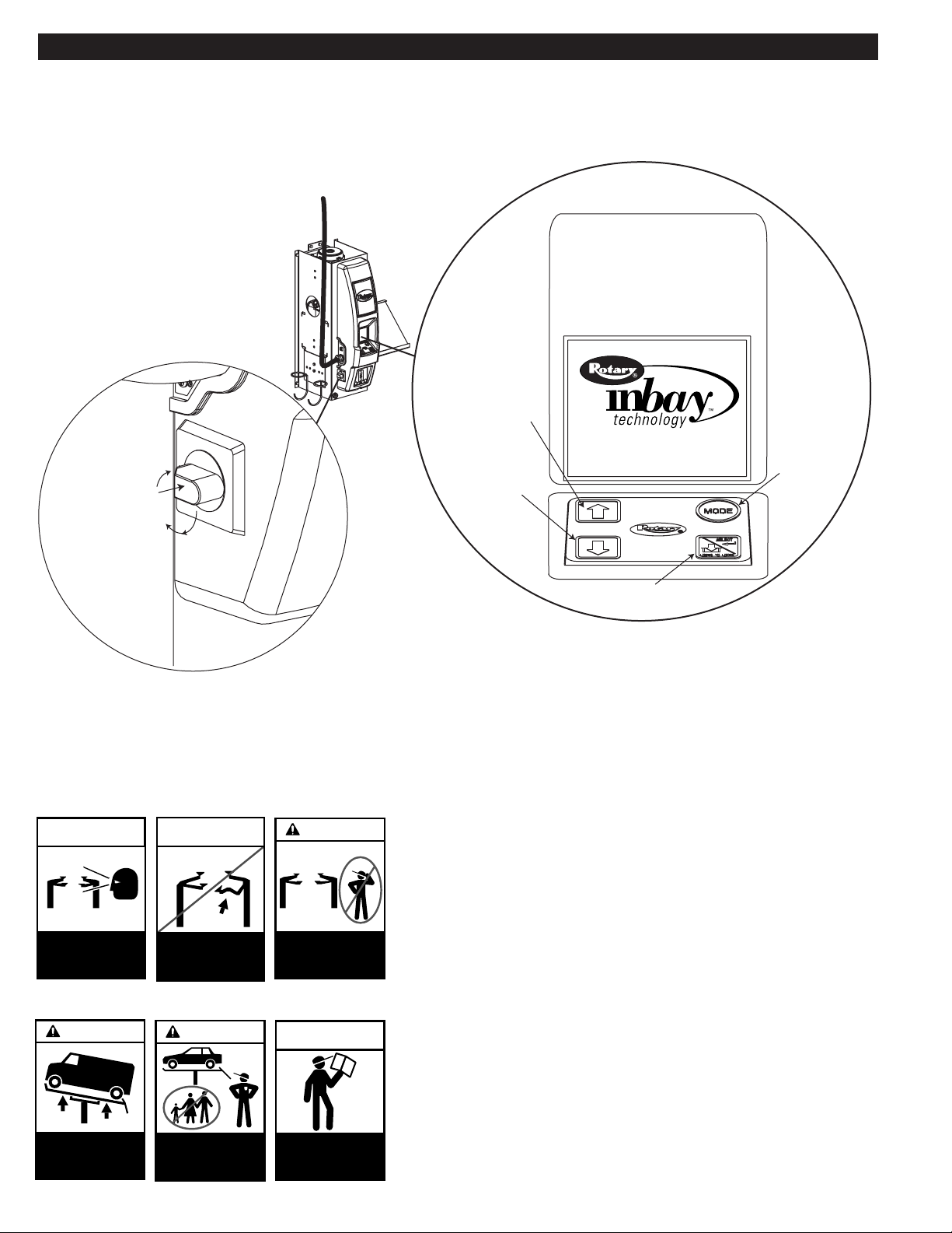
SAFETY INSTRUCTIONS
inbay Master Control Panel
Raise Lift / Scroll Up
1 O
N
FF
Lower Lift / Scroll Down
00/00/00 00:00
Mode Button
SAFETY
INSTRUCTIONS
Proper maintenance
and inspection
is necessary
for safe operation.
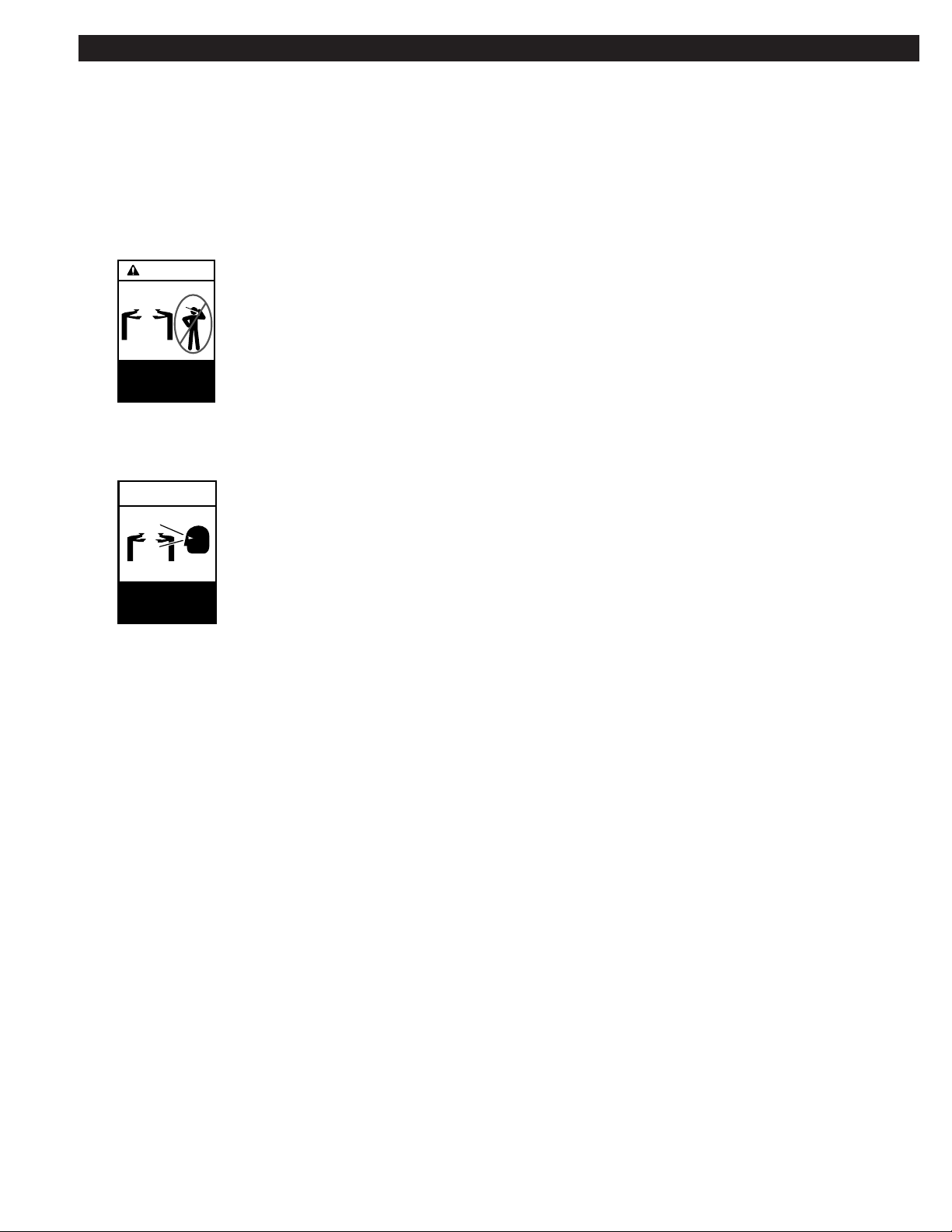
CAUTION
SAFETY
INSTRUCTIONS
Do not operate
a damaged lift.
©
CAUTION
CAUTION
Lift to be used
by trained operator
only.
©
SAFETY
INSTRUCTIONS
Menu Selection / Lower To Locks
• Daily inspect your lift. Never operate if it malfunctions or if it
has broken or damaged parts. Use only qualified lift service
personnel and genuine Rotary parts to make repairs.
?
?
?
• Thoroughly train all employees in use and care of lift, using
manufacturer’s instructions and Lifting It Right and Safety
Instructions supplied with the lift.
©
• Never allow unauthorized or untrained persons to position
vehicle or operate lift.
• Prohibit unauthorized persons from being in shop area while
lift is in use.
Auxiliary adapters
may reduce
load capacity.
Authorized personnel
only in lift area.
©
Read operating
and safety manuals
before using lift.
©
• Do Not permit anyone on lift or inside vehicle when it is
either being raised or lowered.
• Always keep area around lift free of tools, debris, grease and
©
oil.
4
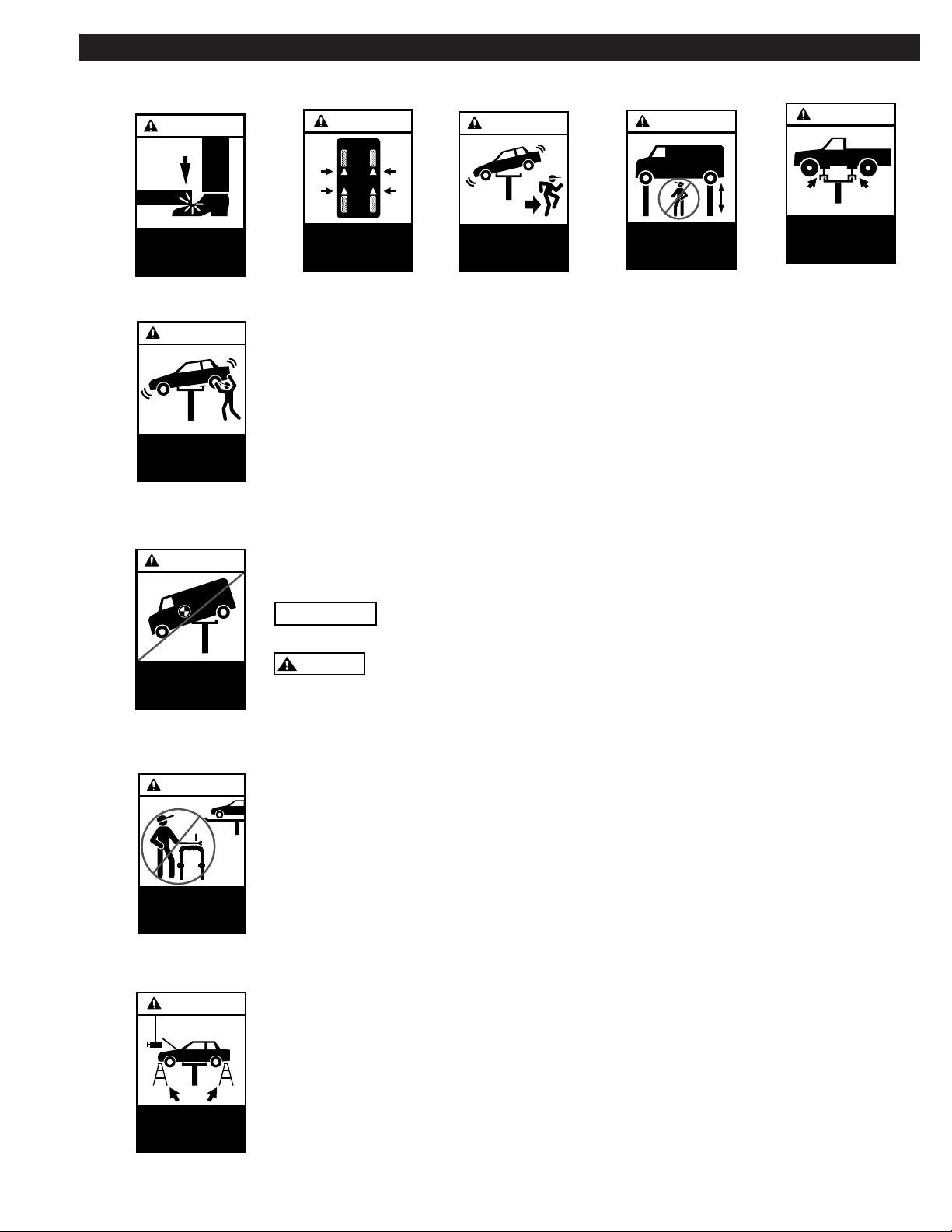
SAFETY INSTRUCTIONS
WARNING
Keep feet
clear of lift
while lowering.
WARNING
Avoid excessive
rocking of vehicle
while on lift.
WARNING
CAUTION
Use vehicle
manufacturer’s
©
lift points.
©
WARNING
Clear area if vehicle
is in danger of falling.
©
WARNING
Remain clear of lift
when raising or
lowering vehicle.
Use height extenders
when necessary
to ensure
©
good contact.
• Never overload lift. Capacity of lift is shown on nameplate affixed to the lift.
• Do Not stand in front of the lift or vehicle while it is being positioned in the lift bay.
• Do Not hit or run over lift arms or adapters. This could damage lift or vehicle. Before
driving vehicle into bay, position arms and adapters to provide unobstructed entrance
onto lift.
©
• Always use all four adapters when raising vehicle. Never use just two adapters to raise
just one side or one end of the vehicle.
• Load vehicle on lift carefully. Position lift adapters to contact the vehicle at vehicle
manufacturer’s recommended lift points.
CAUTION
©
Position vehicle
center of gravity
over lift.
WARNING
Do not override
self-closing
lift controls.
CAUTION
IMPORTANT
CAUTION
©
• Remain clear of lift and vehicle when lowering.
The center cover is designed for foot traffic only.
DO NOT go under vehicle if locking latches are not engaged.
• Always use safety stands when removing or installing heavy components.
• Avoid excessive rocking of vehicle while on lift.
• Clear area if vehicle is in danger of falling.
• Remove tool trays, stands, etc. before lowering lift. Release locking latch before
attempting to lower lift.
©
• Position lift arms and adapters to provide an unobstructed exit before removing vehicle
from lift area.
• Do Not perform any maintenance on the power unit, control valves, air or fluid lines,
hydraulic cylinders, or check fluid level until lift has been fully lowered and all pressure
has been released from system. Follow OSHA Lockout/Tagout procedures as they apply;
reference ANSI Z244.1.
Always use
safety stands when
removing or installing
heavy components.
©
5
OPERATING INSTRUCTIONS
C
A
U
T
IO
N
Lift to be used
by trained operator
only.
©
?
?
?
C
A
U
T
IO
N
Authorized personnel
only in lift area.
©
WARNING
To avoid personal injury and/or property damage, permit only trained personnel to
operate lift. After reviewing these instructions, get familiar with lift controls by running
the lift through a few cycles before loading vehicle on lift.
IMPORTANT
Always lift the vehicle using all four adapters. NEVER raise just one end, one corner, or
one side of vehicle.
WARNING
If Lift is not operating properly, DO NOT use until adjustments or repairs are made by a
qualified lift service personnel.
Observe and heed SAFETY, CAUTION, and
WARNING labels on the lift.
1. Lift must be fully lowered and service bay clear of all
personnel before the vehicle is brought on lift. Do not
stand in the front of a moving vehicle.
2. Position lift arms and adapters to provide unobstructed
entrance of vehicle onto lift.
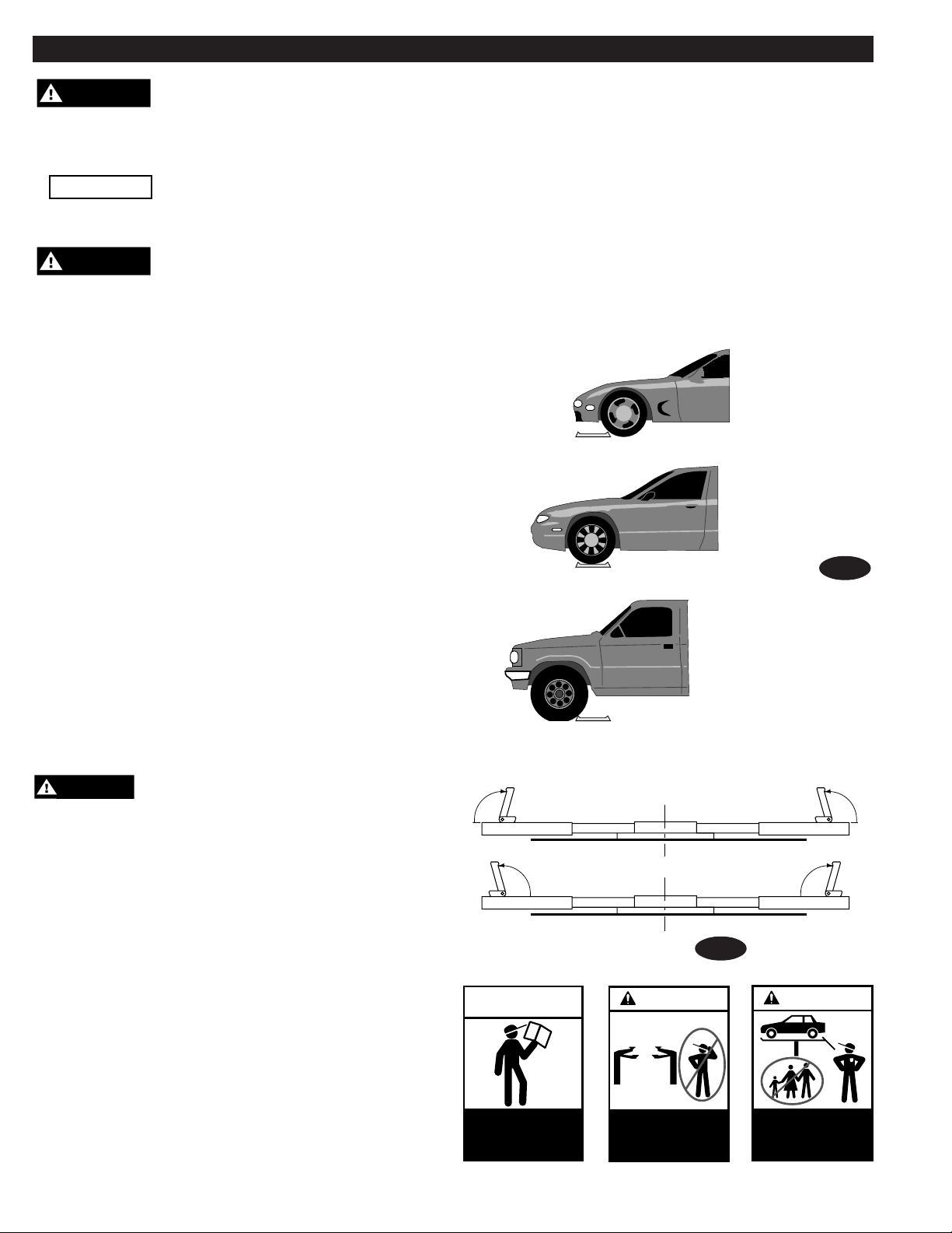
3. Spotting: Spot vehicle on lift with left front wheel in
proper spotting dish position, Fig. 1.
Typical Wheel Spotting Positions
Less than 105"
wheelbase:
position left front
wheel on approach
side of wheel dish.
105"-127"
wheelbase:
position left front
wheel in wheel
dish.
Fig. 1
4. Lift Controls: The lift controls are on the touch pad,
Fig. 5. The lift will cease to run when you stop
pressing the buttons on the touch pad.
5. Loading: Position arms and adapters at the vehicle
manufacturer’s recommended lift points. Use
intermediate, high step or optional adapters/extensions
for under-body clearance when required, Fig. 3 and Fig. 4.
WARNING
Before attempting to lift pick-up trucks or
other truck frame vehicles, be sure that:
A. Vehicle individual axle weight does not exceed one-half
lift capacity.
B. Adapters are in secure contact with frame at vehicle
manufacturer’s recommended lift points, Fig. 3 and Fig. 4.
C. Vehicle is stable on lift and neither “front” nor “tail”
end heavy.
D. Adequate overhead clearance is provided to raise
vehicle to desired height.
E. Rotate front and rear adapter to oppose each other when
using the high step adapter and/or any auxiliary height
extending adapter, Fig. 2.
Larger than 127"
wheelbase:
position left front
wheel just forward
of wheel dish.
Center of Lift
Fig. 2
SAFETY
INSTRUCTIONS
Note: Allow 2 seconds between motor starts. Failure to
comply may cause motor burnout.
Read operating
and safety manuals
before using lift.
6
©
 Loading...