

sss1. Introduction
2-Post Vehicle Lift
SGL35
O
O
PP
EE
RR
AA
TT
II
N
N
GG
aa
n
n
dd
M
M
AA
II
NN
TT
EE
NN
AA
© Rotary Lift, 03/2013 ● 117592 ● Rev. C
NN
CC
EE
M
M
AA
N
N
U
U
AA
LL


EC Declaration of Conformity
according to EC directive 2006/42/EC on machinery (Annex II A)
Name and address of the manufacturer:
BlitzRotary GmbH
Hüfinger Str.55
78199 Bräunlingen, Germany
This declaration relates exclusively to the machinery in the state in which it was placed on the market, and excludes
components which are added and/or operations carried out subsequently by the final user. The declaration is no more
valid, if the product is modified without agreement.
Herewith we declare, that the machinery described below
Product denomination: 2-post vehicle lift
model / type: SGL35
Capacity 3500 kg
machinery / serial number: ………………..
Year of manufacture: 20…
Complies with all essential requirements of the Machinery Directive2006/42/EC
In addition the partly completed machinery is in conformity with the EC Directives 2004/108/EC relating to
electromagnetic compatibility and 2006/95/EC relating to electrical equipment
met in accordance with Annex I No. 1.5.1 of the Machinery Directive 2006/42/EC).
(Protection objectives have been
Harmonised Standards used:
EN 1493: 2010 Vehicle lifts
EN ISO 12100-1 : 2003 Safety of Machinery- Basic concepts
EN ISO 12100-2 : 2003 Safety of Machinery- Basic concepts
EN 60204-1:2006+7/2007 Electrical equipment of machines
EN 349:1993+A1:2008 Safety of machinery - Minimum gaps
EN ISO 13850:2008 Safety of machinery – Emergency stop
EN ISO 14121-1:2007 Safety of machinery - Risk assessment
Other technical standards and specifications used:
BGG 945 inspection of vehicle lifts
BGR 500 management of working appliances
BGV A3 Accident prevention regulation of electric facilities and equipment
The person authorised to compile the relevant technical documentation:
Herr Pohl; Hüfinger Str. 55; 78199 Bräunlingen
Place : Bräunlingen
Date : 19.03.2013
______________________
Frank Scherer
Managing Director
Reg-Nr. 042_2006/42/EG


Contents
1. Introduction
6.4 Recommissioning the lift after incorrect
alignment of the slider blocks .............. 18
1. Introduction .................................................. 2
1.1 About this operating manual ................. 2
1.2 Important information for the machine
operator ................................................. 2
1.3 Specialist for safety related work .......... 3
1.4 In-house accident, health & safety and
environmental information ..................... 3
1.5 Warning and information symbols ......... 3
2. Intended use ................................................ 4
2.1 General .................................................. 4
2.2 Incorrect use .......................................... 4
3. The lift ........................................................... 4
3.1 Functionality .......................................... 4
3.2 System overview ................................... 5
3.3 Technical data ....................................... 6
3.4 Identification of lift.................................. 6
3.5 Permitted weight distribution ................. 7
3.6 Safety mechanisms ............................... 8
3.7 Control box ............................................ 9
4. Safety regulations ..................................... 10
4.1 General operation................................ 10
4.2 Operational safety, breakdowns .......... 10
4.3 Picking up loads .................................. 10
4.4 Up /down ............................................. 10
4.5 Installation, maintenance, servicing .... 10
5. Operation .................................................... 11
5.1 Emergency stop .................................. 11
5.2 Before use ........................................... 11
5.3 Switching on the equipment ................ 11
5.4 Driving the vehicle onto the lift ............ 11
5.5 Up / down ............................................ 11
5.6 Using the lift ......................................... 12
5.7 Before lowering the lift ......................... 12
5.8 Driving the vehicle from the lift ............ 12
5.9 Switch off the system .......................... 13
6. Action in the event of a fault .................... 14
6.1 Operator troubleshooting .................... 14
6.2 Troubleshooting for competent persons15
6.3 Emergency lowering ............................ 17
7. Maintenance ............................................... 19
7.1 Maintenance staff qualification ............ 19
7.2 Safety regulations ................................ 19
7.3 Maintenance schedule ......................... 19
7.4 Cleaning ............................................... 20
7.5 Check the hydraulic oil level ................ 20
7.6 Approved hydraulic oils ........................ 20
7.7 Check the hydraulic component seals . 20
7.8 Inspect and adjust the synchronisation
cables ................................................... 20
7.9 Carry out a function test ....................... 21
8. Repairs ........................................................ 21
9. Safety inspections ..................................... 21
10. Transport, storage ..................................... 21
10.1 Storage ................................................ 21
10.2 Trans port .............................................. 21
10.3 Unpacking ............................................ 22
11. Installation .................................................. 23
11.1 Installation guidelines .......................... 23
11.2 Mechanical installation ......................... 24
11.3 Hydraulic installation ............................ 26
11.4 Electrical connection ............................ 26
11.5 Final assembly of the mechanical unit . 27
12. Commissioning .......................................... 30
13. Disassembly ............................................... 32
14. Disposal ...................................................... 32
14.1 Packaging ............................................ 32
14.2 Environmental procedures for disposal32
14.3 Metals / Electronic waste ..................... 32
ANNEX ................................................................. 33
Diagrams, Spare parts lists, supplementary
instructions
Electrical Circuit diagram
Hydraulic diagram
Spare parts lists
Hydraulic power unit
117592 ● 03/2013
1

1. Introduction
g
1. Introduction
1.1 About this operating manual
The post lift conforms to state of the art technology
and complies with the applicable occupational
health & safety and accident prevention regulations.
Notwithstanding, improper use or use other than
that which is intended may result in a risk of fatal or
physical injury to the user or third parties and may
also result in damage to property.
It is therefore imperative that the relevant people
carefully read and understand this operating
manual.
Read the instructions carefully to prevent incorrect
use, potential hazards and damage. The post lift
should always be operated according to regulations.
Please note the following:
The operating manual must be kept close to the
lift and be easily accessible for all users.
Make sure that you have read and
understood Chapter 4, Safety Instructions
and also the operating instructions on the
machine.
We assume no liability for damage and
operational breakdowns which may occur as a
result of non-compliance with the instructions
contained within this operating manual.
Installation and commissioning of the lifts is
described in detail in Chapters 11 to 13.
Installation may only be carried out by
authorised installation specialists (trained by the
manufacturer) and qualified electricians.
If you should run into difficulties please contact a
specialist, our customer service.
Illustrations may differ from the supplied version
of the machine. Functions or processes to be
carried out remain the same.
Disclaimer:
We assume no responsibility for printing errors,
mistakes and technical changes.
The brands and trade marks mentioned in this
document refer to their owners or the products
thereof.
This is the ori
inal manual in German.
1.2 Important information for the
machine operator
The operating manual contains important
information for safe operation and for the functional
reliability of the lift.
The signed form “Installation record“ must be
sent to the manufacturer to verify the installation
of the lift.
The “Inspection logbook“ contains forms for
verifying the initial, regular, and unscheduled
safety inspections. Use the forms to record the
inspections and add the completed forms to the
inspection logbook.
Design modifications must be entered in the
“Machine master data sheet“.
The machine operator is responsible for ensuring
that the lift is always operated in a safe manner and
the following requirements are met or regularly
carried out.
The operators must be qualified through specialist
training and experience.
The operator must be familiar with the
applicable occupational health & safety and
accident prevention regulations and be
instructed and trained to operate the lift.
The operator must have read and understood
the safety regulations chapter and verified this
with his signature.
If several people work on the post lift, a foreman
must be appointed.
The post lift may only be operated in technically
sound condition with regard to safety.
Maintenance and servicing must be performed
regularly according to the defined schedule.
Safety inspections must be conducted regularly,
and at least once annually in accordance with
chapter 9.
The inspection logbook must be kept up-to-date.
This operating manual as well as the annexed
instructions must always be kept with the lift.
This also applies if the lift is sold or re-installed
at a new location.
For safety reasons, unauthorised modifications
or alterations to the lift are not permitted. In case
of an unauthorised modification, the operating
permit is cancelled, and the Declaration of
Conformity becomes null and void.
2
117592 ● 03/2013

1. Introduction
1.3 Specialist for safety related
work
The post lift must be inspected after commissioning
and at regular intervals but at least annually.
as well as after the replacement of safety-related
parts during maintenance work.
Safety-related work and safety inspections on the lift
may only be carried out by people trained to do so.
These people are generally known as certified
experts and competent persons.
Certified experts are persons who may inspect
and assess lifts (freelance specialist engineers,
TÜV certified experts), based on their training
and experience.
They are familiar with the relevant occupational
health & safety and accident prevention
regulations.
Competent persons (skilled people) are
persons who have sufficient knowledge and
experience of lift systems. They have attended
a special training course at the lift manufacturer.
Competent persons are customer service fitters
for the manufacturer or authorised dealer.
people. Non-compliance may lead to
death or serious injury.
Risk of death or injury
Potential risk to life and health of
WARNING
CAUTION
ATTENTION
people. Non-compliance may lead to
serious or critical injury.
Risk of injury
Potentially hazardous situation.
Non-compliance may lead to minor
or moderate injury.
Damage to property
Potentially hazardous situation. Noncompliance may lead to damage to
property.
Other Symbols
INFO-Symbol Useful information and tips.
i
Bullet point:
For lists with key information on the
respective subject.
1. Action:
Carry out the detailed steps in order.
1.4 In-house accident, health &
safety and environmental
information
This operating manual does not contain information
and instructions with actions in the event of
accidents and health risks.
The in-house operating instruction must be supplied
by the operator of the lift.
1.5 Warning and information
symbols
Warnings are identified by the following symbols,
depending on the hazard classification.
Be especially aware of safety and hazards when
working in situations identified by warning symbols.
Comply with the occupational health & safety and
accident prevention regulations which are applicable
in your country.
Risk of death or injury
Direct threat to life and health of
Action symbol
Carry out the detailed steps in order.
DANGER
117592 ● 03/2013
3

2. Intended use
2. Intended use
2.1 General
Risk of injury!
WARNING
To prevent injury to persons or property, the
lift should only be operated by trained
operators.
After reading this manual, become familiar
with operating the lift by conducting several
trial runs before loading a vehicle onto the lift.
The lift is designed to raise and lower cars and
delivery vehicles for repair, maintenance, and
cleaning in a normal workshop environment.
The lift may only be used according to regulations,
in a fully functional condition according to the
technical data in chapter 3.3.
The manufacturer assumes no liability for
damage of any kind which arises through
incorrect, erroneous, or unreasonable use.
3. The lift
3.1 Functionality
The lift is designed to raise vehicles to the
optimum height for maintenance, cleaning, or
repair work.
The lift is operated by pressing buttons on the
control unit which is attached to one of the
posts.
The vehicle is raised and lowered in jog mode.
Steel cables ensure that the vehicle is raised
horizontally.
The max load capacity of the whole lift is 3500 kg
and may not be exceeded.
Operators may stand under the raised load.
Risk of injury if used incorrectly.
DANGER
ALWAYS raise the vehicle with all four (4)
adapters! Never lift only one end, one corner
or one side of the vehicle.
2.2 Incorrect use
Incorrect use presents a residual risk to the life and
health of the people working in the lift zone.
The manufacturer assumes no liability for damage
resulting from use other than the intended purpose
and misconduct.
The following is prohibited:
Climbing onto or riding on the load or pick-up
equipment.
Loitering under the load when raising or
lowering.
Raising vehicles loaded with hazardous
substances.
Installing the lift in areas at risk from explosion.
Using the lift for washing vehicles and under any
other conditions not expressly specified in the
operating manual,
4
117592 ● 03/2013
1
3. The lift
3.2 System overview
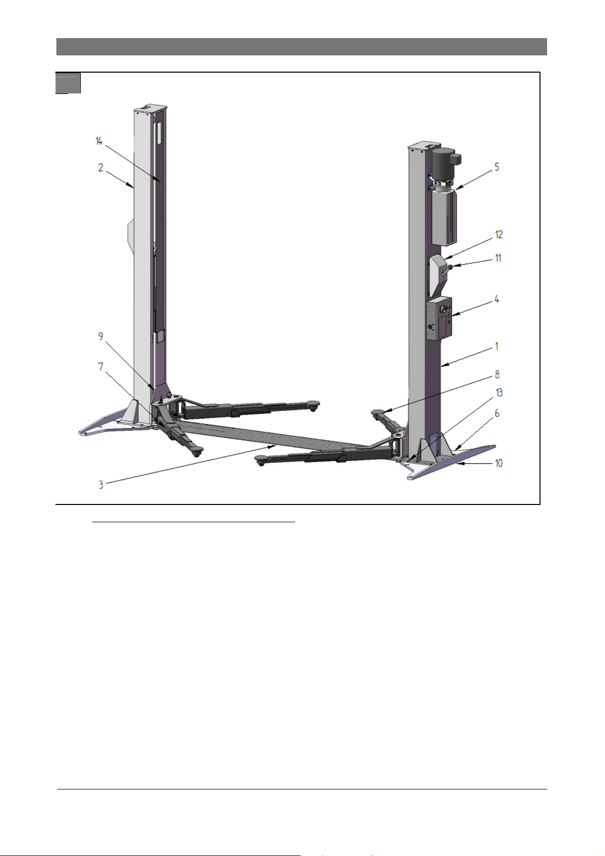
Figure 1: Example of a post lift
1 Primary column
2 Secondary column
3 Drive-through ramp
4 Control unit
5 Hydraulic unit
6 Column base plate
7 Arm
8 Adapter
9 Slide
10 Base plate support (optional extra)
11 Lever for latch mechanism
12 Latch mechanism cover
13 Hole for anchor bolts
14 Cover plate
117592 ● 03/2013
5
3. The lift
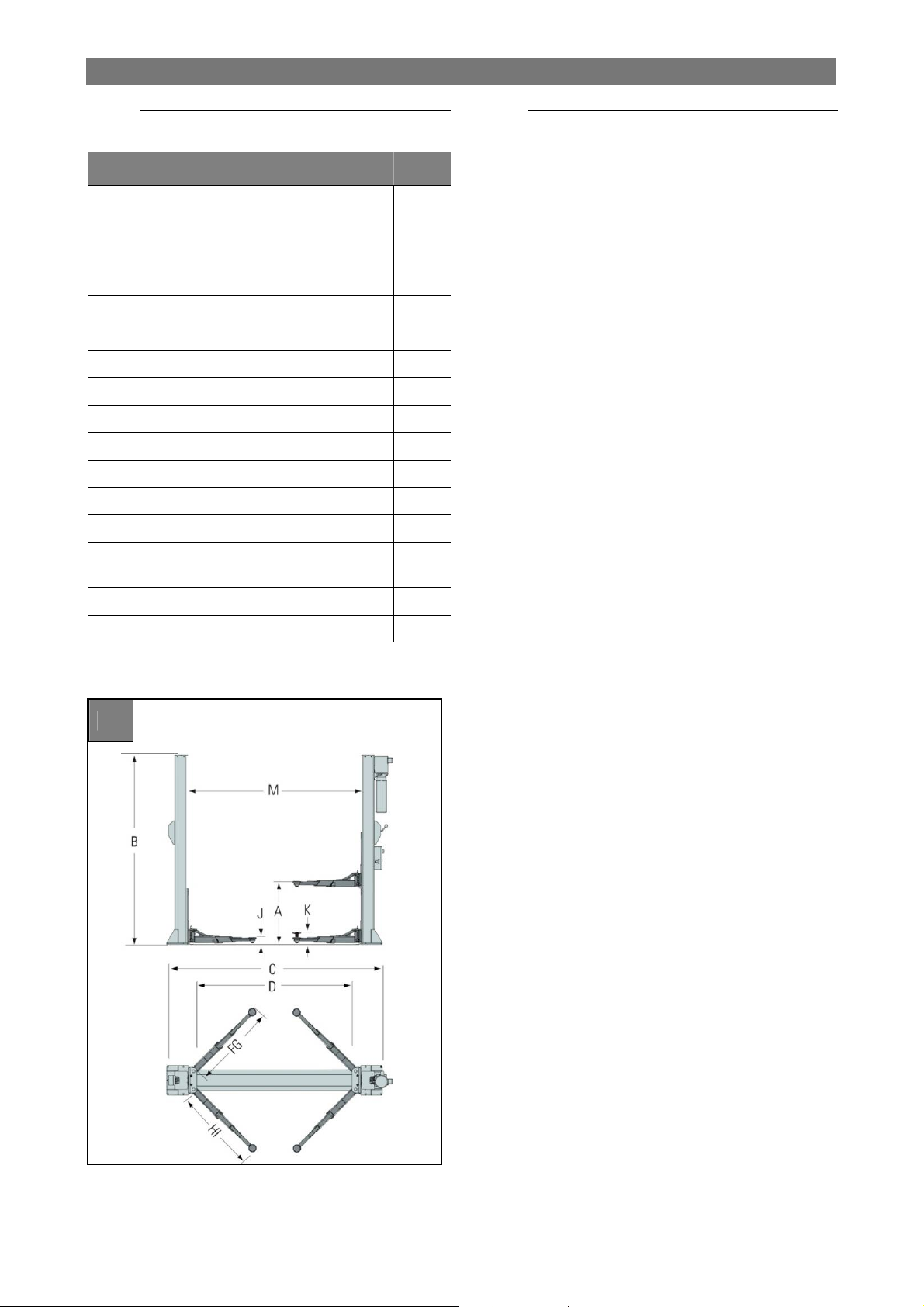
3.3 Technical data
SGL35
Load capacity / Lift cylinder [kg] 3500
A Rise [mm] 1828
B Overall height [mm] 3160
C Overall width [mm] 3320
D Drive-through clearance [mm] 2388
F Reach front arm min. [mm] 600
G Reach front arm max. [mm] 1280
H Reach rear arm min [mm] 600
I Reach rear arm max. [mm] 1280
J Adapter height min. [mm] 110
K Adapter height max. [mm] 166
L Inside columns [mm] 2688
M Motor [kW] 2.2
Electrical connection
(3 phases)
Rise time [sec] 40
Required ceiling height [mm] 3170
400 V
50 Hz
3.4 Identification of lift
The customer service department of your authorised
dealer can react quicker to your maintenance
queries if you specify the lift, serial number, and any
possible accessories.
The information below is given on the information
plates:
BlitzRotary GmbH
Hüfinger Str.55
78199 Bräunlingen
Deutschland
Telephone: +49 771 9233 0
Fax: +49 771 9233 10
Model SGL 35
Model year 20__
Serial number _____________
Load capacity (kg) 3500
Power supply (V) 230 / 400
Power consumption (kW) 2.3
Actuating power (kW) 2.2
Phases 3 + PE
Frequency (Hz) 50 / 60
Specified hydraulic pressure (bar) 205
2
6
117592 ● 03/2013
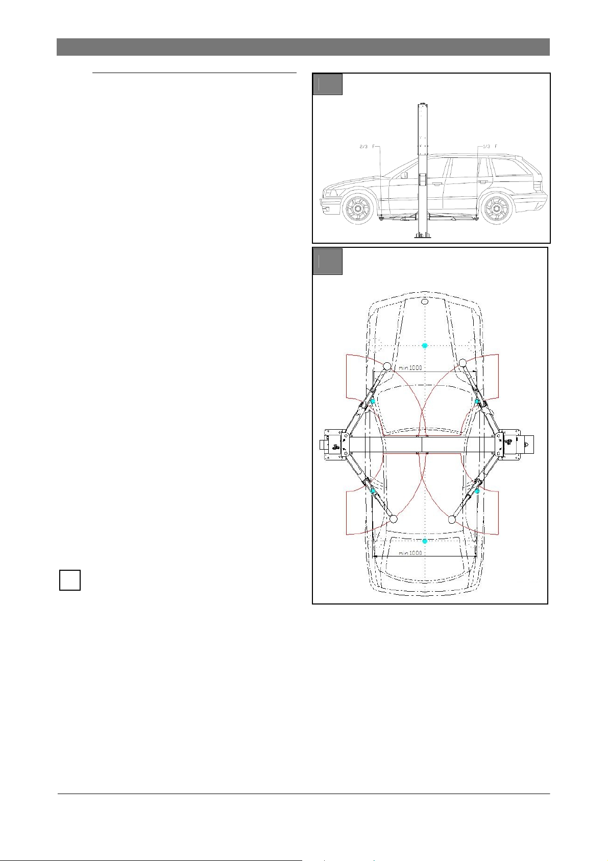
3.5 Permitted weight distribution
Figure 3: Vehicle centre of gravity
The weight distribution on the adapters is
reversible for this post lift: The heavy load can
either be placed on the long or the short arms
P1 (1/3) - P2 (2/3) of the maximum load.
3
3. The lift
Figure 3: Minimum distance between two
adapters
Not less than 1000 mm
If the distance is less, the load capacity of the lift
will be reduced
4
The weight distribution must match the
i
guidelines specified in this chapter. We
therefore recommend distributing the weight
as centrally as possible in relation to the axis
of the posts.
117592 ● 03/2013
7
3. The lift
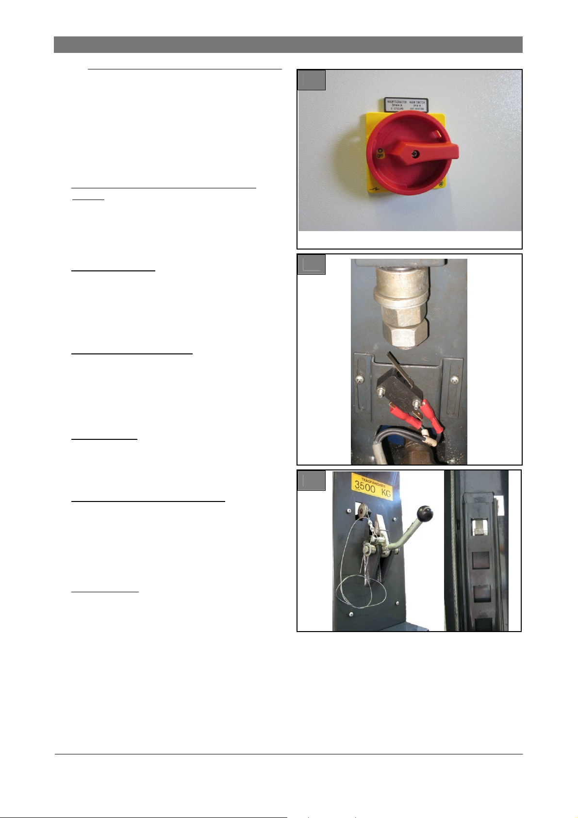
3.6 Safety mechanisms
Figures 5 ... 9: Safety mechanisms
Electrical
Emergency stop button on the control unit
(Figure 5)
Broken chain and slack chain switch (lifting
chain): consists of a micro switch, which is fitted
in each column at the bottom. This module
permits any movement of the lift to be halted if a
chain is broken or unusually slack. (Figure 6)
Hydraulic
Broken line switch: consists of a valve in a
hydraulic cylinder. This valve is designed to limit
the lowering rate if the hydraulic line fails
(breaks). It is set so that the lowering rate does
not exceed the nominal rate by more than 1.5 x.
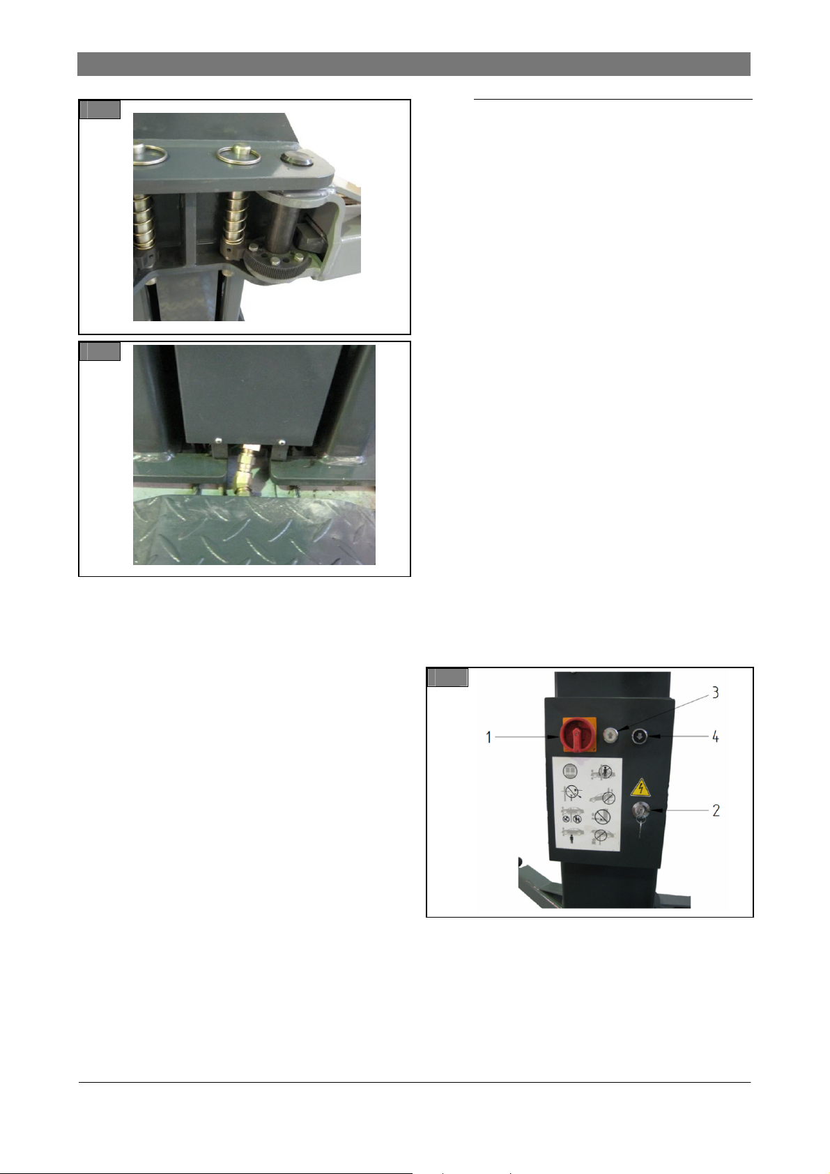
Mechanical
Mechanical latching system: consists essentially
of a spring-loaded latch which is fitted on each
column, as well as a bar with notches on each
slider block. This latch and bar assembly stops
the lift from accidentally dropping in the event of
a leak in the hydraulic system or breaks in the
system components (Figure 7)
Arm restraints: consist of a ring gear on the end
of the arm which engages the pinion of the lift
slide. This assembly is activated as soon as the
slide leaves its lowest point to prevent the arms
from slewing. (Figure 8)
Mechanical synchronisation control: consists of
two synchronisation cables which connect the
slider blocks to each other. The cables prevent
incorrect alignment of one slider in relation to
the other slider if the weight is unevenly
balanced crosswise. (Figure 9)
Ergonomics
5
6
7
Foot protection: metal plates on both sides of
the base plate of both columns and a metal
baffle plate in the outside of the arms which
prevent a foot becoming trapped under the
slider block or arm(s).
8
117592 ● 03/2013
3. The lift
8
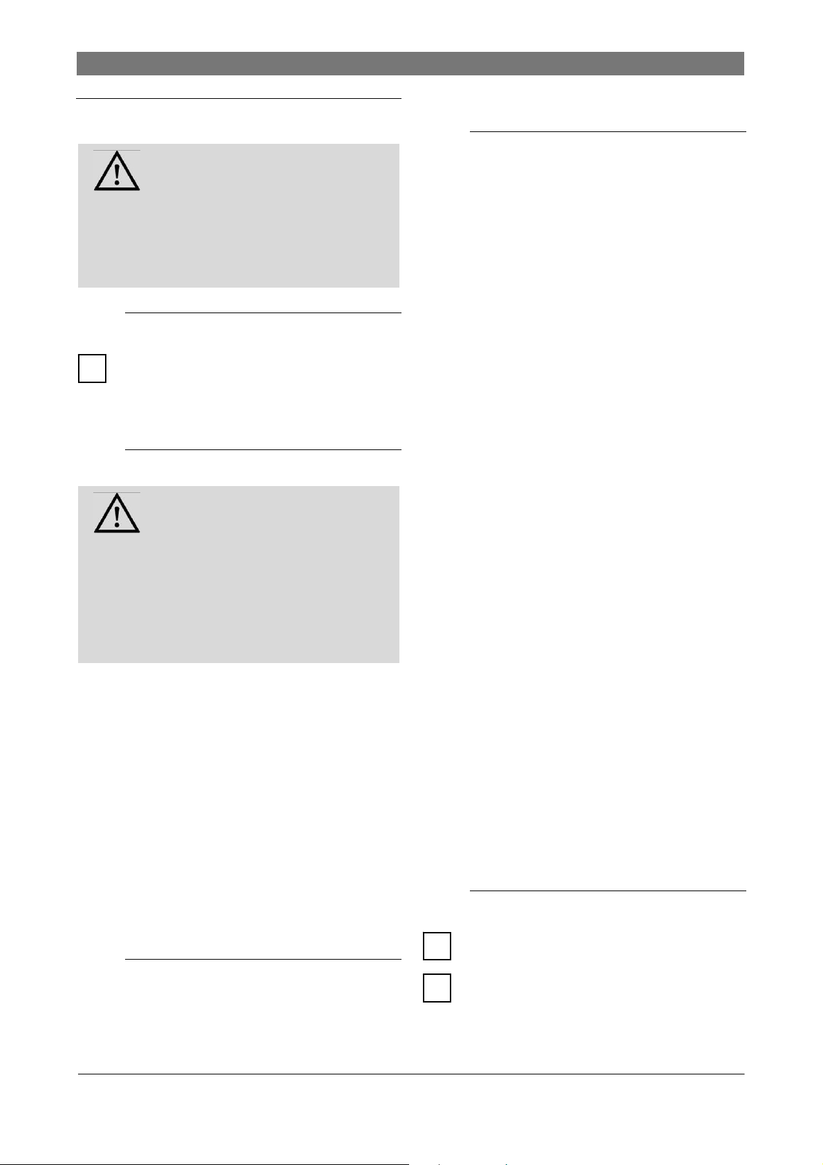
3.7 Control box
(see figure 11)
1 Main switch, emergency stop
To connect the lift to the mains supply, turn the
switch to ”1", to disconnect from the power
supply turn it to ”0".
2 Control box key
Opens the control box for maintenance
purposes.
3 Up button
9
Press this button to actuate the hydraulic power
unit and raise the slider block. This works on the
dead man’s switch principle, meaning that when
the button is released, raising of the lift is halted
immediately.
4 Down button
When this button is pressed and the latching
system lever is activated at the same time (s.
Figure 7), the slider block is lowered. This
works on the dead man’s switch principle,
meaning that when the button is released,
lowering of the lift is halted immediately. The
system is also locked by the latching
mechanism. Before lowering, the latching
mechanism must first be released. If the lever
cannot be released, the latch has engaged.
The lift must first be raised a little to finally
release the system. Only then can you lower
the lift.
11
117592 ● 03/2013
9

4. Safety regulations
4. Safety regulations
Comply with the following regulations!
4.1 General operation
Only operate the lift if you have read and
understood this operating manual. Also refer to
the brief operating instructions on the lift.
The total permitted weight is 3,500 kg .
Only persons who are 18 years old, are trained
in operating the lift, and have signed the
handover sheet are permitted to operate the lift.
Vehicles with low ground clearance or with
optional extras should be checked beforehand.
They can only be lifted if no damage can be
caused.
Work on the lift may only be carried out if the
main switch is turned off and locked.
Do not:
● Carry people on the lift.
● Climb onto the lift or the load.
● Ride on the lift with equipment.
Emergency lowering of a vehicle may be done
only by competent persons.
Switch off equipment when not in use.
Do not use the lift in proximity to a potentially
combustible or flammable atmosphere.
4.2 Operational safety,
breakdowns
The operational safety of the lift must be
inspected regularly.
If breakdowns occur or if there are missing
safety components, shut down the lift
immediately. Inform the supervisor or customer
service.
During the raising and lowering process, no-one
should loiter within range of the moving load
and the pick-up points.
Briefly raise the lift to check that the vehicle
pick-up points are secure. The latches must be
properly engaged. Only then lift the vehicle to
the desired height. The lift and the vehicle may
otherwise become dangerously unstable.
The area within range of moving loads and pick-
up points must be free of obstacles.
4.5 Installation, maintenance,
servicing
Installation, maintenance, and servicing work
may only be carried out by trained and
authorised specialists, with the system switched
off and made safe.
Electrical work may only be carried out by
qualified electricians.
Only specialist staff with specialist knowledge
and experience may work on hydraulic
equipment.
Repairs on the safety equipment of the lift may
only be carried out by competent persons.
Follow the maintenance schedule, document
maintenance work.
Only use OEM parts.
Following design modifications or repair work on
safety relevant parts, the lift must be inspected by
a certified expert.
4.3 Picking up loads
Before lifting with the arms, check the pick-up
points on the vehicle for load capacity,
corrosion, damage, and modifications.
Only lift vehicles at the points approved by the
manufacturer.
Do not carry out any work on a raised vehicle
which may affect the stability of the pick-up
points.
4.4 Up /down
Only operate the lift if it poses no danger to
people.
10
117592 ● 03/2013
5. Operation
Risk of injury if an incorrect
procedure is followed during
DANGER
If there are indications of faults such as
unusual noise or leaks, shut down the lift
immediately, secure it, and inform the
supervisor.
To prevent any movement of the lift in an
i
emergency (malfunction or defect), set the
main switch to ”0" and lock it with the key
switch.
DANGER
No one may loiter under the vehicle when the
lift is moving, clamber onto the lift, or climb
into the car. The movement of the slider block
and the arms must not be hampered by
objects (e.g. tools), before they have reached
their end position.
Inspect the lift - see ”Inspection and
maintenance instructions for operators". Never
activate the lift if it is showing a malfunction or
damaged parts.
Before the vehicle is placed on the lift, it must be
fully lowered and everyone must move away
from the work area.
If problems occur, set the main switch to ”0“.
The lift may only be inspected by authorised
and qualified staff. Before all maintenance or
repair work, lock the main switch with the key
switch and if necessary, disconnect the lift from
the power supply.
Do NOT use the lift as a crane or jack for other
lifting mechanisms!
breakdowns.
5.1 Emergency stop
5.2 Before use
Risk of injury if an incorrect
procedure is followed before use
5. Operation
5.4 Driving the vehicle onto the
lift
Unauthorised or untrained persons may NOT
operate the lift and may NOT lift the vehicle.
Do NOT drive against or over the arms
Do NOT overload the lift: Refer to the load
capacity plate on the lift
Refer to the weight distribution details in
the ”Area of use" chapter. Never exceed the
figures in this chapter in order not to expose
the operator to danger.
Make sure that the vehicle is centred
according to the longitudinal axis of the lift
and that the pick-up points of the vehicle
chassis are correctly positioned in relation to
the adapters.
Make sure that the arms do not directly touch
the vehicle chassis. Before lifting, check again
that all adapters are correctly positioned
below the pick-up points.
Check that the arm restraints are properly
engaged before lifting the vehicle.
Make sure that no danger arises from lifting
the load, and after lifting the load for a few
centimetres, check that the vehicle is correctly
positioned and secure.
It is essential that the vehicle is lifted at the
points indicated by the manufacturer for this
purpose and only accessories supplied by the
manufacturer of the lift.
When raising and lowering, ensure that the
motion of the lift is smooth and does not
chatter and that the load is always stable. If a
vehicle is unstable or the operation of the lift
does not appear normal, halt operation of the
lift immediately. If possible, lower the lift again
with extreme care. If necessary, check and
correct the vehicle position. If the vehicle
continues to be unstable, set the main switch
to ”0“ and contact the maintenance technician
at your authorised dealer.
5.5 Up / down
The lift must be lowered and raised steadily,
i
so that the load does not shift.
5.3 Switching on the equipment
To connect the control unit to the power supply,
set the main switch to ”1".
117592 ● 03/2013
If the vehicle does not remain stable, halt all
i
lift movement immediately.
Then turn the main switch to ”0“ and lock it.
11

5. Operation
The vehicle must now be lowered by an
i
authorised competent person.
ONLY use adapter extensions from the lift
manufacturer. DO NOT use wood or concrete
i
blocks or other improvised extensions.
Check the condition of the pick-up points on the
i
vehicle. These should be free of grease, oil and
dirt. Arms swing under the vehicle and position the
adapter on the pick-up points recommended by the
vehicle manufacturer (Fig. 4). Bring the adapter to
the corresponding height to stop the car straight
and properly balanced.
When raising and lowering, monitor the lifted
i
vehicle constantly. If the lift is not synchronised,
pause the movement and determine the cause.
Monitor the tension of the synchronisation cables
i
through the inspection window in the plate frame,
and if there are irregularities, shut down the lift
and contact the service department.
Raising
1. Press the Up button. Raise the vehicle
slightly.
2. Check that the vehicle pick-up points are
secure.
3. Press the Up button. Raise the vehicle to the
desired height.
4. Make sure that each pinion engages the ring
gear as soon as the slider block loses contact
with the floor.
lever and push the DOWN button to lower the
lift to the required level.
2. If you cannot pull the lever down, the latching
mechanism has engaged. Press the UP and
DOWN buttons at the same time so that the
slider block rises and the lever is released. Then
lower the vehicle.
The latch mechanism, the lever, and the "Up"
and "Down" switches are dead man’s
i
switches. The lift is raised and lowered as
long as the buttons and the lever are
engaged.
3. Set the main switch to “0“.
5.6 Using the lift
Prevent extreme vibrations from the vehicle
whilst it is positioned on the lift
If required, always use safety stands as
stabilisers when removing or fitting heavy
components (i.e. engines, gearboxes etc). Use
4 safety stands
When lowering, stay outside the range of the lift.
Do not stand in the lowering zone.
Wear protective goggles when working
underneath the vehicle
If necessary, also use support straps to stabilise
the vehicle on the arm when disassembling
parts.
5. If one of the pinions does not engage the ring
gear, the bolt with the pull ring at the top can be
seen to protrude further than normal at the top
on the guide shaft of the pinion (Fig. 8, in
normal position). In this case, lower the slider
block and re-position the problematic arm.
6. Release the SAFETY lever and the Up button
as soon as the working height has been
reached.
7. When the required height has been reached,
the lift can engage the safety latch.
8. Set the main switch to ”0", as soon as the
necessary working height has been reached.
Down
1. Connect the control unit to the power supply
and set the main switch to “1“, pull the SAFETY
12
5.7 Before lowering the lift
Remove all tools and other objects from the lift
zone.
Ensure that no-one is in the lift zone.
Ensure that there are no people or objects in the
drive-off zone before driving the vehicle from the
lift.
5.8 Driving the vehicle from the
lift
1. Secure the vehicle against rolling.
2. Ensure that the arms are in their outermost
position on full drive-thru position before driving
the vehicle from the lift.
117592 ● 03/2013
 Loading...