

Rotary MCH418, MCH618 Installation-safety-operation-maintenance
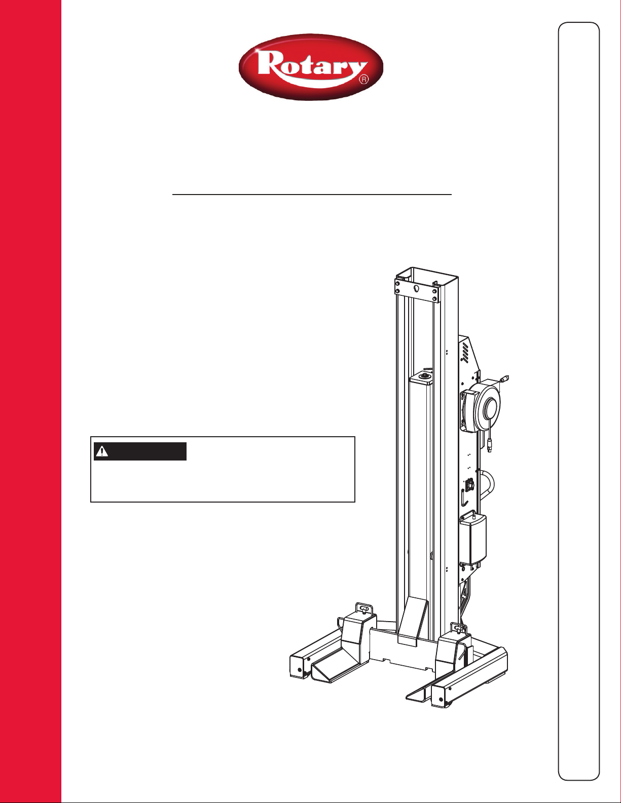
MCH418/MCH618
Four Post/Six Post Mobile Column Lift
24V DC Powered
MCH418 Capacity 72,000 lbs.
MCH618 Capacity 108,000 lbs.
18,000 lbs. per column
N
N
S
S
T
T
A
A
L
L
L
L
A
A
T
T
O
O
N
N
S
S
A
A
F
F
E
E
I
I
I
I
-
-
IMPORTANT
Installation and Service of Automotive Lifts
before installing lift.
Reference ANSI/ALI ALIS,
Safety Requirements for
T
T
Y
Y
-
O
O
P
P
E
E
R
R
A
A
T
T
I
O
O
N
N
-
M
M
A
A
I
N
N
-
I
-
I
© June 2015 by Vehicle Service Group. All rights reserved. CO9304.4 IN20540
Rev. G 6/12/2015
T
T
E
E
N
N
A
A
N
N
C
C
E
E

Index
WARNING
WARNING
Set-Up Instructions .................................................. 2
Safety Instructions ................................................... 4
Owner/Employer Responsibilities .......................... 4
Quick Start Operating Instructions ........................ 5
Emergency Lowering ................................................ 7
Detailed Operating Instructions .............................. 8
Set-Up Instructions
Follow these instructions to ensure a satisfactory set-up
and operation of the lift.
• After set-up and inspection of the lift, please return this
booklet to the literature package and give to lift owner/
operator. Literature package should be kept attached to
controls for easy access.
1. Unloading: Rotary’s Mobile Lift System units are shipped
in the vertical position.
2. After unloading, remove and discard protective
wrapping.
Battery Charging ........................................................ 9
Maintenance Instructions ..................................... 10
Trouble Shooting ...................................................... 11
Lift Lockout/Tagout Procedure .............................. 12
Wiring Diagram ........................................................ 13
Battery wires are clearly marked/labeled inside the unit
itself.
Install tie-down straps on batteries as shown.
Close lift and re-install M8 BHCS removed earlier.
After the batteries and fluid have been added, screw M20
bolt and M10 socket head bolts clockwise on wheel jack
and front of superstructure to adjust unloaded column
ground clearance, Fig. 1. Ground clearance is determined
by how far the bolts are turned. When the column is
loaded, it will automatically lower to the floor.
NOTE: Unit is shipped without batteries and
without power unit fluid. Installation of both
batteries and fluid MUST be completed prior
to lift operation. Failure to do so will result in air
entering the system. The unit will then have to be
bled.
3. To move the column, remove protective banding and
wheel clamps from wheel jack. The forklift brackets can be
removed from the side of the column if desired.
4. Open power unit cover by removing the 3 M8 BHCS
(Button Head Cap Screw). Fill power unit tank with
ISOVG32 hydraulic oil. Tank capacity is approximately 111/2 quarts (11 liters). Fill until fluid is just barely visible on
dipstick.
5. Install two batteries in location shown, Fig. 1. Through
our research Rotary recommends Exide® brand battery
part number NG-27 or DEKA® brand battery part
number DC31DT. Different batteries meeting the below
specifications may be used but performance can vary.
Recommended Battery Specifications:
12V DC Sealed Deep Cycle Battery
Size 31 Frame Group
105 AH Capacity (At 20 AH Rate)
Stud Terminals with Stainless Steel Wing nuts
Permit only trained personnel to
operate lift. After reviewing these instructions,
become familiar with the lift controls by running the lift
through a few cycles before loading a vehicle on lift.
Observe and heed SAFETY and WARNING labels on
the lift.
This motor has internal arcing or
sparking parts. To minimize the Risk of Explosion, DO
NOT expose to flammable vapors.
OPERATING CONDITIONS: Lift is not intended for
outdoor use or storage and has an operating ambient
temperature range of 41º-104ºF (5º-40ºC).
DO NOT use lift in a manner other than intended.
Included (but not limited to) examples of unapproved
uses of the lift are: lifting vehicle by only one side,
lifting different axles with a column pair (lifting on the
diagonal), and lifting non-approved items.
6. Bleed mobile columns:
a.) Raise forks 150-200mm do not lift forks high enough to
engage locks.
b.) Loosen bleed screw to release air from system.
c.) Close screw and repeat steps a and b until there is no
air in the system and fluid runs clear.
2
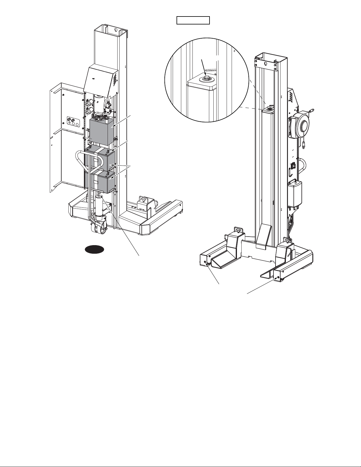
IMPORTANT
Power Unit Tank
IMPORTANT! Negative
Post Must Be Located
On This Side
Battery Locations
Do Not Exceed Torque Values
On Bleeder Screw
Torque Values: 177-230 In/Lbs (20Nm-26Nm)
Bleed Screw
Fig. 1
M20 Bolt
Adjust For
Ground
Clearance
DO NOT use on asphalt. Lift must be on concrete
with a minimum strength of 3000PSI and a minimum
thickness of 4.5”. Maximum allowed floor slope is 1/8”
per foot side to side of vehicle and 1/4" per foot front
to rear of vehicle. DO NOT use on a suspended floor
structure without specific approval from structural
engineer.
Upon completion of the assembly of the lift, the lift is
to be operated to assure proper function. Observe for
locks operating in all locking positions, each side lifts
equally, hydraulics do not leak, all electrical controls
function as labeled, all pneumatics are functional
and leak free, ramps rotate freely (if applicable), and
proper clearances with all items in bay have been
maintained.
M10
Socket Head
Adjust For
Ground
Clearance
Ensure tires are properly inflated before lifting. DO
NOT exceed tire load rating when raising vehicle.
DO NOT raise/lower only one side of a vehicle.
Lift only on same axle. DO NOT stagger between
axles.
DO NOT drive over or pinch electrical cables.
Operate the lift with a typical vehicle and observe to
assure the same items for proper functioning.
3

SAFETY INSTRUCTIONS
• Inspect your lift daily. Never operate if it
malfunctions or if it has broken or damaged parts.
Use only qualified lift service personnel and genuine
Rotary parts to make repairs.
• Thoroughly train all employees in use and care of lift,
using manufacturer’s instructions and “Lifting It Right”
and “Safety Instructions” supplied with the lift.
• Never allow unauthorized or untrained persons to
position vehicle/lift or operate lift.
• Prohibit unauthorized persons from being in shop
area while lift is in use.
• Do Not permit anyone on lift or inside vehicle when
it is either being raised or lowered.
• Do Not operate lift while batteries are charging.
• Always keep area around lift free of tools, debris,
grease and oil.
• Never Overload lift. Capacity of lift is shown on
nameplate affixed to the lift.
• Do Not hit or run over lift forks or base. This could
damage lift or vehicle. Before driving vehicle into
area, position lift units to provide unobstructed
entrance onto lift area.
• Load vehicle on lift carefully. Position lift forks to
fully contact the vehicle tires. Release parking
break on vehicle. Raise lift until tires clear the floor.
Check lift forks for secure contact with vehicle tires.
Raise lift to desired working height.
• Do Not block open or override self-closing lift
controls, they are designed to return to the Off or
Neutral position when released.
• Remain clear of lift and vehicle when lowering.
• Avoid excessive rocking of vehicle while on lift.
• Clear area if vehicle is in danger of falling.
• Remove tool trays, stands, etc. before lowering lift.
• Position lift units to provide an unobstructed exit
before removing vehicle from lift area.
• Do Not perform any maintenance on the control
panels until the power has been shut off to the lift.
• Do Not operate equipment with a damaged cord or
if the equipment has been dropped or damaged.
The Owner/Employer:
• Shall ensure that lift operators are qualified and that they are trained in the safe use and operation of the lift using the
manufacturer’s operating instructions; ALI/SM 93-1, ALI Lifting it Right safety manual; ALI/ST-90 ALI Safety Tips card;
ANSI/ALI ALOIM-2000, American National Standard for Automotive Lifts-Safety Requirements for Operation, Inspection
and Maintenance; ALI/WL Series, ALI Uniform Warning Label Decals/Placards; and in the case of frame engaging lifts,
ALI/LP-GUIDE, Vehicle Lifting Points/Quick Reference Guide for Frame Engaging Lifts.
• Shall establish procedures to periodically inspect the lift in accordance with the lift manufacturer’s instructions or ANSI/
ALI ALOIM-2000, American National Standard for Automotive Lifts-Safety Requirements for Operation, Inspection and
Maintenance; and The Employer Shall ensure that lift inspectors are qualified and that they are adequately trained in the
inspection of the lift.
• Shall establish procedures to periodically maintain the lift in accordance with the lift manufacturer’s instructions or
ANSI/ALI ALOIM-2000, American National Standard for Automotive Lifts-Safety Requirements for Operation, Inspection
and Maintenance; and The Employer Shall ensure that lift maintenance personnel are qualified and that they are adequately trained in the maintenance of the lift.
• Shall maintain the periodic inspection and maintenance records recommended by the manufacturer or ANSI/ALI
ALOIM-2000, American National Standard for Automotive Lifts-Safety Requirements for Operation, Inspection and Maintenance.
• Shall display the lift manufacturer’s operating instructions; ALI/SM 93-1, ALI Lifting it Right safety manual; ALI/ST-90 ALI
Safety Tips card; ANSI/ALI ALOIM-2000, American National Standard for Automotive Lifts-Safety Requirements for Operation, Inspection and Maintenance; and in the case of frame engaging lifts, ALI/LP-GUIDE, Vehicle Lifting Points/Quick
Reference Guide for Frame Engaging Lifts; in a conspicuous location in the lift area convenient to the operator.
• Shall provide necessary lockout/tagout means for energy sources per ANSI Z244.1-1982 (R1993), Safety Requirements for
the Lockout/Tagout of Energy Sources, before beginning any lift repairs.
• Shall not modify the lift in any manner without the prior written consent of the manufacturer.
4
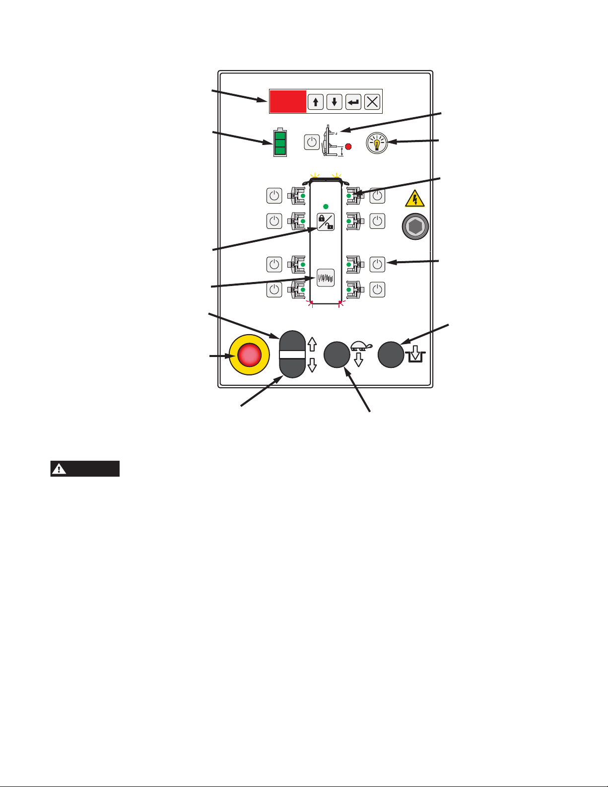
Battery Charge Indicator
Slow Lower
Quick Start Operating Instructions
WARNING
Control Panel Diagram
Data Information
Display and Buttons
System Configuration
Lock/Unlock
Single/Pair/All Mode
Raise
Height Limit Setting
Lights on/off
(Optional Accessory)
Yellow, Green, Red
Activation LED’s
(8 Total)
Activate Column Buttons
(8 Total)
Lower To Locks
1. The service area must be clear of all personnel before
the vehicle is positioned.
minimum strength of 3000 psi.
2. Spotting: Position the vehicle in the location where it is
to be lifted.
Note: See Fig. 2 for the general arrangement of each lift
column.
3. Loading:
Position one column at a lifting wheel location. Position
so that the forks are under the tire and the unit is pushed
in as far as possible, Fig. 3. Ensure fork width is adjusted
to properly accommodate the tire/wheel size. Turn on the
Power Up Switch, Fig. 4.
4. Using the Control Panel and the bus diagram as a
reference (see graphic above), press the Activate Column
Button relative to the location where the column was just
placed. The column will show Green when activated.
E-Stop
Lower
Locate lift on level concrete surface with a
5. Plug the fixed length communication cable from the cord
reel into the bottom of the control panel.
6. Position next column at second wheel using loading
instructions from step 3.
7. Run the reel-end of the communication cable from the
first column and plug into the side of the control panel on
the second column. Turn on second column. Again, using
the Control Panel and the bus diagram as a reference, press
the Activate Lift Button relative to the location of the second
column. The lift will show Green when activated. The first
lift you activated should now be flashing yellow on your
control panel.
8. Repeat step 5 thru 7 for remaining columns. When
the entire system of columns is complete, press the
System Configuration Lock/Unlock button to lock the lift
configuration for operation.
NOTE: The electrical communication cables do not
have to make a complete loop. You do not have to plug
the last lift back into the first lift.
5
 Loading...