

Page 1

Issue 5 Original version Nov 2014
1
PUMA MAGNETIC DRILLING MACHINE
Model No. SMARTPUMA1 & SMARTPUMA3
This machine (Serial No ) is CE approved.
Rotabroach Ltd
Imperial Works, Sheffield Road
Sheffield, South Yorkshire
United Kingdom
S9 2YL
Tel: +44 (0) 114 2212 510 Fax: +44 (0) 114 2212 563
Email: [email protected] Web site: www.rotabroach.co.uk
Page 2
Issue 5 Original version Nov 2014
2
Thank you for purchasing our Smart Puma magnetic drill.
We would really like your feedback on the machine.
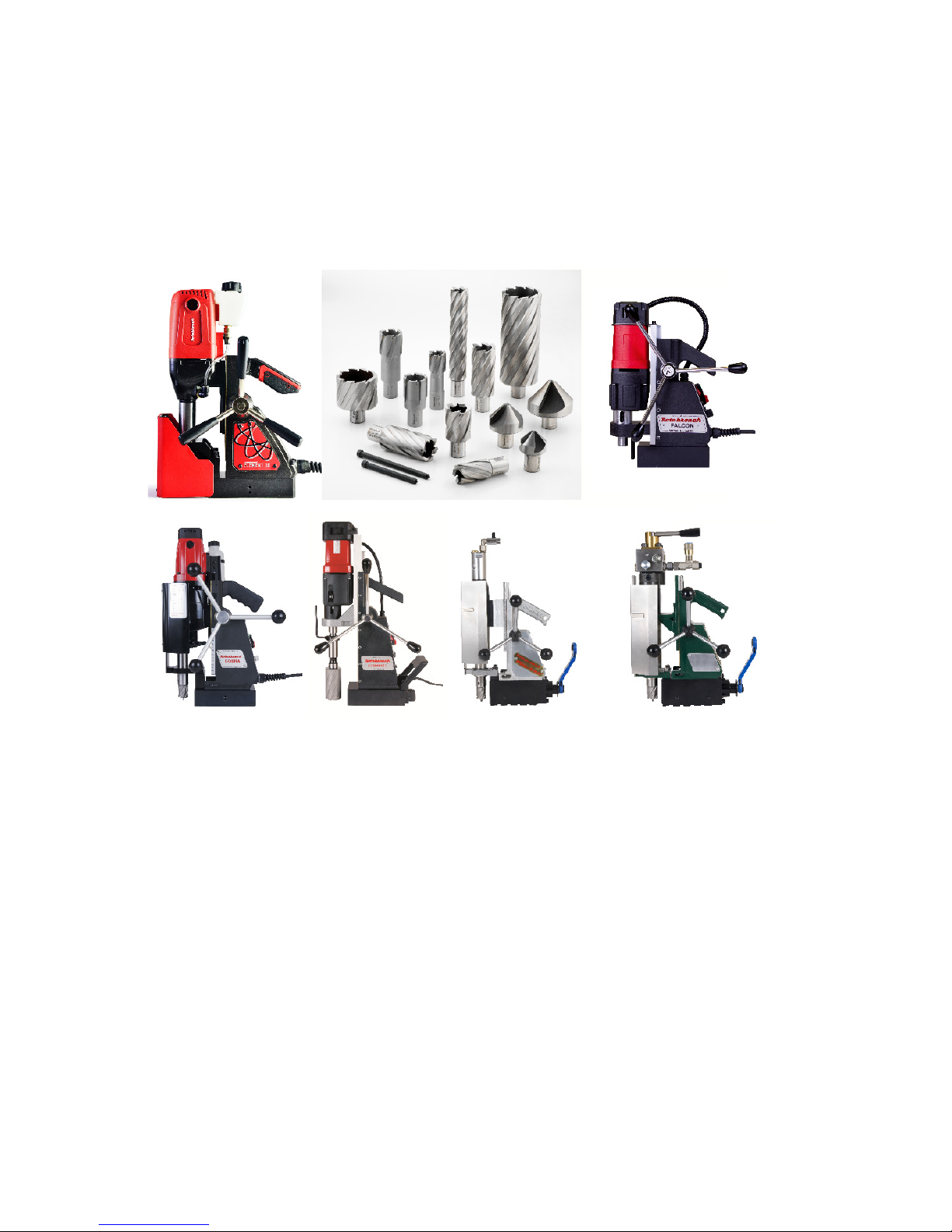
Other Products by Rotabroach™:
Thank you for your purchase of our product.
For more information please visit our website at www.rotabroach.co.uk
Or contact our sales department on +44 (0) 114 2212 510
Page 3

Issue 5 Original version Nov 2014
3
CONTENTS
Page
1) Intended Use 4
2) General Safety 4
3) Machine Specification 6
4) Operating Instructions 7
5) Cutsmart Feature 8
6) Mounting of cutters 9
7) Remedies for hole making problems 9
8) Wiring Diagram 10
9) Exploded diagram of machine 11
10) Exploded diagram of motor and gearbox 13
11) Pipe adaptor Kit 15
12) Chuck conversion 16
13) Maintenance 16
14) Trouble shooting 18
15) Cutter Selection, Speeds and Feeds 19
16) Warranty 20
Page 4

Issue 5 Original version Nov 2014
4
1) INTENDED USE
The intended use of this magnetic drill, is to drill holes in ferrous metals. The magnet is used to hold the drill in
place whilst the drill is functioning. It is designed for use in fabrication, construction, railways, petrochemical
and any other applications when drilling ferrous metal.
Any deviation from its intended use will not be covered by warranty.
2) GENERAL SAFETY RULES
WARNING! When using electric tools basic safety precautions should always be followed to reduce the risk of fire, electric
shock and personal injury, including the following.
Read all these instructions before attempting to operate the machine.
Remove the power supply before carrying out any adjustment, servicing or maintenance.
1. Keep work area clear - cluttered areas and benches invite injuries.
2. Consider work area environment;
• Do not expose tools to rain.
• Do not use tools in damp or wet locations.
• Keep work area well lit (500 Lux recommended).
• Do not use tools in the presence of flammable liquid or gases.
• Ensure there is adequate space to gain access to the plug, mains and motor on/off switches.
3. Guard against electric shock:
Avoid body contact with earthed or ground surfaces (e.g. pipes, radiators, cookers and refrigerators). Electric safety
can be further improved by using a high-sensitivity (30 m A/0.1s) residual current device (RCD).
4. Keep other persons away! DO NOT let untrained persons, especially children, touch the tool or the extension cord and
keep them away from the work area.
5. Store idle tools when not in use. All tools should be stored in a dry locked-up place, out of reach of children.
6. Do not force the machine. It will do the job better and safer at the rate for which it was intended.
7. Use the right tool;
• Do not force small tools to do the job of a heavy duty tool.
• Do not use this tool for purposes not intended: e.g. do not use the magnetic drill to cut tree logs.
8. Dress properly;
• Do not wear loose clothing or jewellery; they can be caught in moving parts.
• Non-skid footwear is recommended when working outdoors.
• Wear a protective hair covering to contain long hair. This will reduce the risk of entanglement.
9. Use protective equipment when using this machine;
• Use safety glasses to prevent debris from damaging eyes.
• Use ear defenders or ear plugs for hearing protection.
• Use face or dust masks if cutting operations create dust.
• Use protective gloves to prevent swarf or debris cutting the skin.
10. When using the drill, always ensure a safe operating distance from any swarf and do not reach into the cutting area,
or near the cutter, when the machine is running.
11. Connect dust extraction and collecting equipment, if devices are provided, ensuring these are properly connected and
used.
12. Do not abuse the cord; never pull the cord to disconnect it from the socket. Keep the cord away from heat, oil and
sharp edges.
12. Secure work where possible, use clamps or a vice to hold the work. It is safer than using your hand.
13. Do not overreach! Keep proper footing and balance at all times.
14. Maintain tools with care;
• Keep cutting tools sharp and clean for better and safer performance.
• Regularly check the machine for any wear or damage.
Page 5

Issue 5 Original version Nov 2014
5
• Ensure the machine is clean and free from debris prior to use.
• Remove from the mains prior to any maintenance.
• Follow instructions for lubricating and changing accessories.
• Inspect tool cords periodically and if damaged have them repaired by an authorized Rotabroach service facility.
• Inspect extension cords periodically and replace if damaged.
• Keep handles dry, clean and free from oil and grease.
15. Disconnect tools when not in use, before servicing and when changing accessories such as cutters, disconnect tools
from the power supply.
16. Form the habit of checking to see that keys and adjusting wrenches are removed from the tool before turning it on.
17. Avoid unintentional starting. Ensure the magnet is OFF before plugging the machine in.
18. Use extension leads only intended for outdoor use when the tool is used outdoors.
19. WARNING! The vibration emissions during actual use can differ from the declared total value depending on the ways
in which the tool is being used.
20. Stay alert! Watch what you are doing, use common sense and do not operate the tool when you are tired. DO NOT
operate the machine when under the influence of alcohol or ANY illegal substances.
21. Check for damaged or missing parts before use of the tool; it should be carefully checked to determine that it will
operate properly for its intended function.
22. Warning! The use of any accessory or attachment, other than ones recommended in this instruction manual, may
present a risk of personal injury.
23. Have your machine repaired by a qualified Rotabroach technician.
This electric tool complies with the relevant safety rules. Qualified persons using original spare parts should only carry
out repairs, otherwise this may result in considerable danger to the user.
24. Never operate the machine if parts are missing or damaged.
25. Never direct jets of water or flammable liquids over the drill.
26. Operator must be physically able to handle the weight of the machine.
27. Operator should be trained in the use of the machine.
Foreseeable Misuse
During operation, failure to keep the cable away from the machine body, will result in the cable damaged by drill bit, causing
electric conduction and other accidental injury.
Before operation, when plugging the power source, failure to turn all the switches to position <off>, may result in accidental start-
up from the machine, causing accidental injury.
During suspended operation, failure to tie the safety belt to fasten the magnetic drill, when power failure or power down suddenly,
causing magnetic drill to get out of the work surface and resulting in the accident.
Other risks
During operation, wear loose clothing or jewellery, failure to wear protective hair covering to containing long hair, they can be
caught in moving parts, may present an accidental injury.
During operation,put in effort to push and press the machine, will result the magnet getting out of the work surface suddenly,
causing accidental injury.
Before mounting or removing the drill bit, failure to disconnect the supply, will result the accidental start-up, causing personal
injury.
Page 6
Issue 5 Original version Nov 2014
6
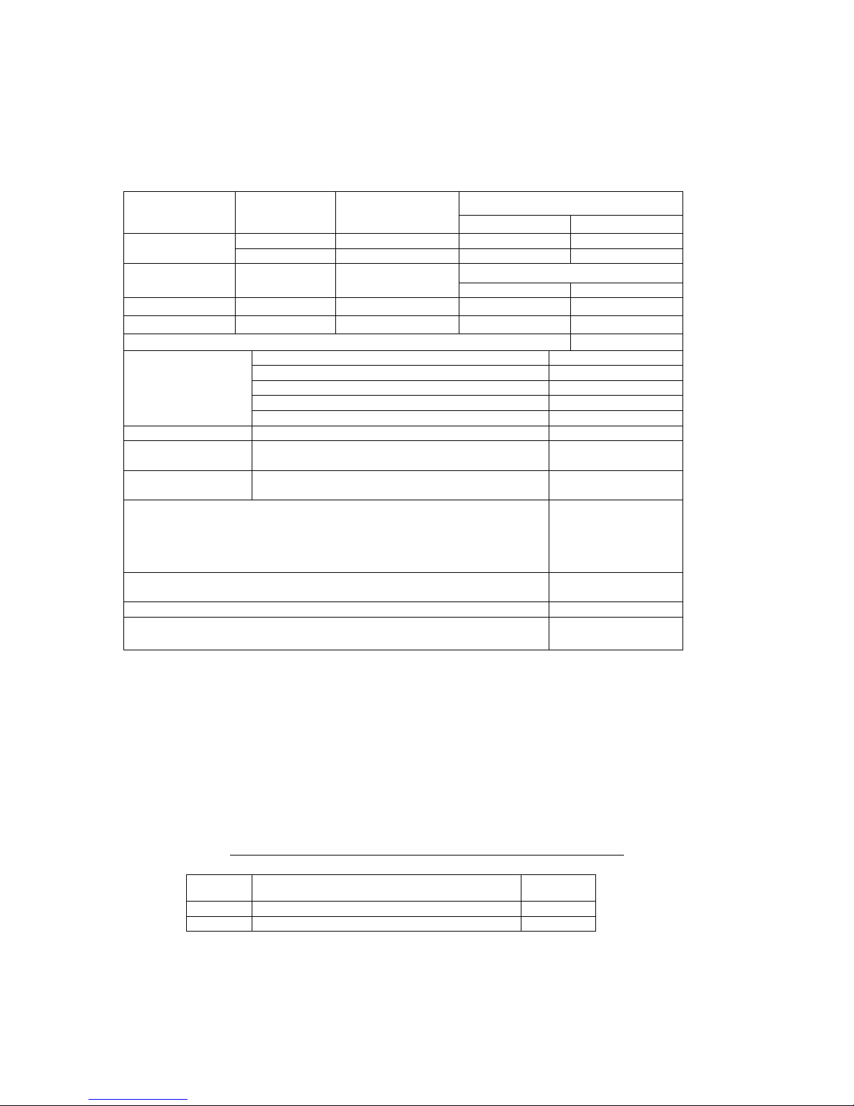
3) SPECIFICATION
Maximum hole cutting capacity in .2/.3C steel = 30mm dia. x 25mm deep
Arbor bore = 19.05mm (3/4”) dia.
Model Voltage (V)(AC) Normal Full Load
Watts (W)
SMARTPUMA1 110V 50-60Hz 800
SMARTPUMA3 230V 50-60Hz 800
Electro Magnet
Model Voltage (V)(DC) Normal Full Load
Amps (A) Watts (W)
SMARTPUMA1 110 0.45 45
SMARTPUMA3 230 0.225 45
Total Normal Full Load (magnet + motor) 845
Overall
Dimensions
Height (maximum extended) 410mm
Height (minimum) 360mm
Width (including Hand wheel) 170mm
Length Overall (including Guard) 250mm
Magnet Footprint 165mm x 80mm
Net Weight 11.20kgs
Stroke With Arbor
With Drill chuck
30mm max
65mm
No Load
Speed
All voltages 600rpm
Tractive Force of Magnet at 20º C (25mm min. plate thickness)
The use on any material less than 25mm thick will progressively reduce the
magnetic performance. If possible substitute material should be positioned under
the magnet and work piece to equate to a suitable material thickness. If this is not
possible an alternative secure method of restraining the machine MUST be used.
8000N
Maximum hand/arm vibration magnitude (measured at handle during operation in
accordance with ISO5349 using a 22mm dia. cutter through 13mm mild steel plate.
2.95 m/s²
Estimate of vibration exposure. Operation 30 holes @ 1 minute/hole. 0.39 m/s² A(8)
Average noise level during cutting at operators ear position.
L
PA
Max. 88.3 dB(A)
LWA Max. 101.3dB(A)
Suitable only for a single phase 50-60 Hz A.C. power supply
DO NOT USE ON D.C. SUPPLY
Do not use your magnetic drill on the same structure when arc welding is in progress.
D.C. current will earth back through the magnet and cause irreparable damage.
WARNING: THIS APPLIANCE MUST BE EARTHED!
NB: ANY MODIFICATIONS TO THIS MACHINE WILL INVALIDATE THE GUARANTEE
List of Contents with Magnetic Dill Unit
Check
List
RD4329 Safety Strap YES/NO
RD4088 4mm A/F Tee Handled Hexagon Key YES/NO
Page 7

Issue 5 Original version Nov 2014
7
4) OPERATING INSTRUCTIONS
READ BEFORE USING THE MACHINE
• When using electrical tools, basic safety precautions should always be followed to reduce the risk of electric shock, fire, and personal
injury.
• Ensure the magnet is OFF before plugging in the machine.
• Do NOT use in wet or damp conditions. Failure to do so may result in personal injury.
• Do NOT use in the presence of flammable liquids, gases or in high risk environments. Failure to do so may result in personal injury.
• BEFORE activating the machine, inspect all electrical supply cables (including extension leads), and replace if damaged. DO NOT use if
there are any signs of damage.
• Only use extension cables approved for site conditions.
• BEFORE activating the machine, ALWAYS check the correct function of all operational systems, switches, magnet etc.
• BEFORE operating, the machine MUST be securely restrained to a fixed independent feature (by using safety strap RD4329, or other
means) to reduce the potential free movement, should the magnet become detached from the work piece. Failure to do so may
result in personal injury.
• ALWAYS wear approved eye protectors, ear defenders and recommended PPE at ALL times when operating the machine.
• Disconnect from power source when changing cutters or working on the machine.
• Cutters and swarf are sharp, ALWAYS ensure that hands are adequately protected when changing cutters or removing swarf. Use a
tool or brush where necessary to remove any swarf or the cutter from the arbor.
• Before operating the machine, ALWAYS ensure cutter-retaining screws are secured tightly.
• Regularly clear the work area and machine of swarf and dirt, paying particular attention to the underside of the magnet base.
• ALWAYS remove tie, rings, watches and any loose adornments that might entangle with the rotating machinery before operating.
• ALWAYS ensure that long hair is securely enclosed by an approved restraint before operating the machine.
• Should the cutter become stuck in the work piece, stop the motor immediately to prevent personal injury. Disconnect from power
source and turn arbor to and fro. DO NOT ATTEMPT TO FREE THE CUTTER BY SWITCHING THE MOTOR ON AND OFF. Wear safety
gloves to remove the cutter from the arbor.
• If the machine is accidentally dropped, ALWAYS thoroughly examine the machine for signs of damage and check that it functions
correctly BEFORE resuming drilling.
• Regularly inspect the machine and check for any damaged or loose parts.
• ALWAYS ensure when using the machine in an inverted position that only the minimum amount of coolant is used and that care is
taken to ensure that coolant does not enter the motor unit.
• Cutting tools may shatter, ALWAYS position the guard over the cutter before activating the machine. Failure to do so may result in
personal injury.
• On completion of the cut, a slug will be ejected. DO NOT operate the machine as the ejected slug may cause injury.
• When not in use ALWAYS store the machine in a safe and secure location.
• ALWAYS ensure that approved ROTABROACH™ agents conduct repairs.
OPERATION
• Keep the inside of the cutter clear of swarf. It restricts the operating depth of the cutter.
• Ensure that the coolant bottle contains sufficient cutting oil to complete the required operating duration. Refill as required.
• Occasionally depress the pilot to ensure cutting fluid is being correctly metered.
• To start the machine follow the control panel operation instructions.
• ALWAYS switch off the motor by depressing the RED stop button. DO NOT switch off the motor by turning the magnet switch to
zero.
• Apply light pressure when commencing the cut of a hole until the cutter is introduced into the work surface. Pressure can then be
increased sufficiently to load the motor. Excessive pressure is undesirable, it does not increase the speed of penetration and will
cause the safety overload protection device to stop the motor, (the motor can be restarted by operating the motor start button), and
may cause excessive heat which may result in inconsistent slug ejection
• Always ensure that the slug has been ejected from the previous hole before commencing to cut the next.
• If the slug sticks in the cutter, move the machine to a flat surface, switch on the magnet and gently bring the cutter down to make
contact with the surface. This will usually straighten a cocked slug and allow it to eject normally.
• Apply a small amount of light oil lubricant regularly to the slide and arbor support bearing.
• Cutter breakage is usually caused by insecure anchorage, a loosely fitting slide or a worn bearing in the arbor support. (Refer to
routine maintenance instructions).
• Only use approved cutting fluid. Rotabroach cutting fluid has been specially formulated to maximise the cutters performance. It is
available in 1 litre (RD208) and 5 litre (RD229).
EXTENSION CABLE SELECTION
The machines are factory fitted with a 3 metre length of cable having three, 1.5mm² conductors, LIVE, NEUTRAL and EARTH. If it becomes
necessary to fit an extension cable from the power source, care must be taken in using a cable of adequate capacity. Failure to do so will
result in a loss of traction by the magnet and a reduction of power from the motor.
Assuming a normal AC supply of the correct voltage, it is recommended that the following extension lengths shall not be exceeded:
For 110v supply: 3.5metres of 3 core x 1.5mm²
For 230v supply: 26 metres of 3 core x 1.5mm² or 17metres of 3 core x 1.0mm²
Page 8
Issue 5 Original version Nov 2014
8
5) CUTSMART FEATURE
‘CutSmart’ is a new feature from Rotabroach.
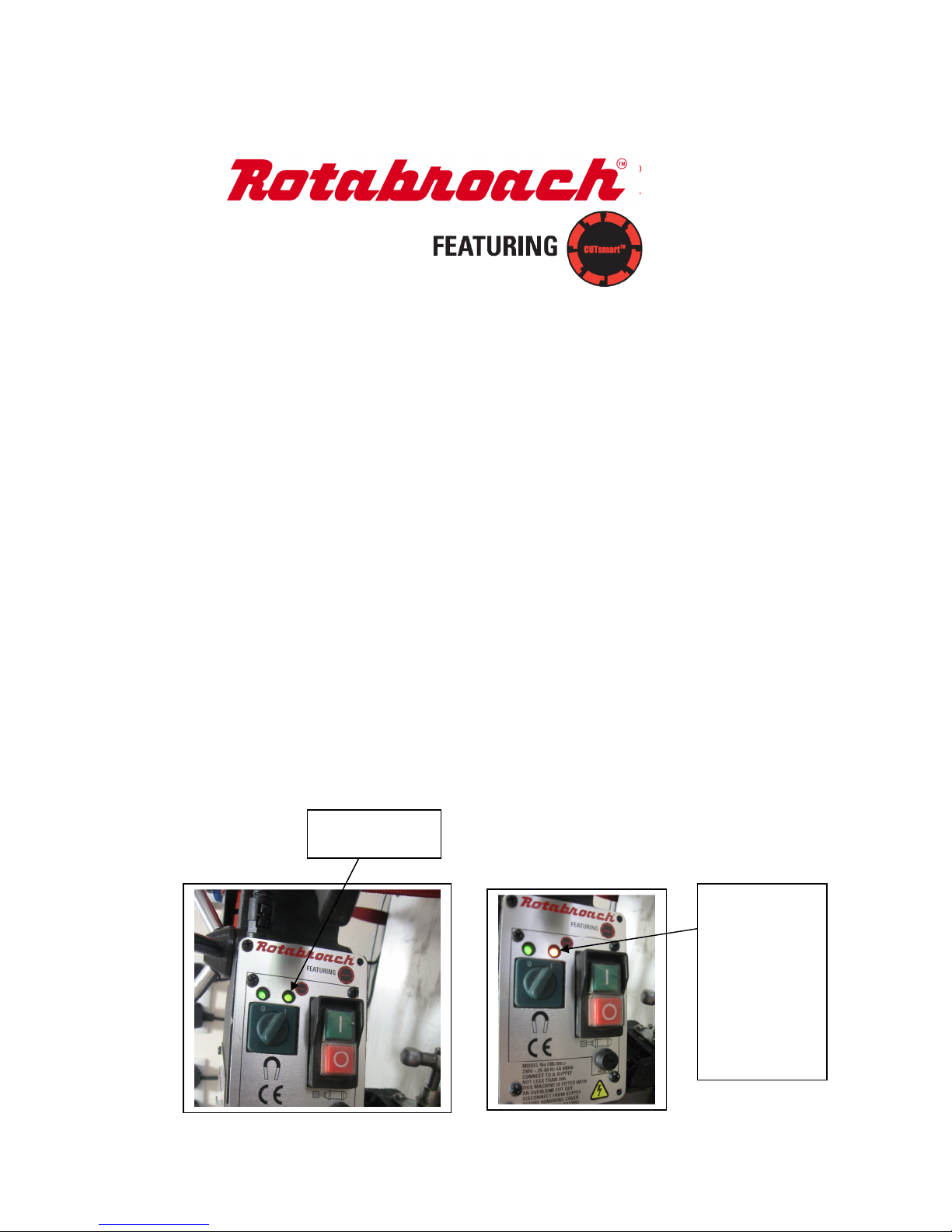
Designed to help you to get the best out of your machine. It does this by way of a visual indicator.
The visual indicator shows when you are using the drill correctly within its specification this is done by way of a
Tri colour LED to the Right of the magnet on LED.
During operation if you are drilling correctly this will stay GREEN. However as you put more pressure onto the
drill increasing its workload above its correct operation the LED will start to change colour to ORANGE. This
indicates that you are putting more wear on the machine and the cutter which will eventually cause damage to
your machine. If further pressure is put on the machine the LED will eventually turn RED and the motor will cut
off and will not be allowed to be turned back on for approximately 5 seconds. This is a safety feature to protect
you and the machine from damage.
Ideally to get the most out of your machine you need to keep the LED green when drilling. If it starts to turn
orange release some pressure.
The panels are set to cut off when the machine reaches the following currents.
110V panel – approximately 17 amps
230V panel – approximately 10 amps
The magnet is also protected by a 2A fuse
Care must be taken when handling the PCB as they are static sensitive please ensure you are earthed. As the
PCB contains some delicate components please do not flash test this equipment.
New Cutsmart
indicator
Indicator turns
orange when too
much pressure is
added on the
cutter. Will turn
Red and cut
power to motor if
machine is given
too much force
for the motor to
Page 9

Issue 5 Original version Nov 2014
9
6) MOUNTING OF CUTTERS
(See exploded view of complete machine)
The machine has been made to accept cutters having 19.05mm (3/4”) dia. shanks.
The following procedure is to be used when mounting cutters.
• Lay the machine on its side with feed handles uppermost, ensuring arbor is wound down to its lowest point to enable access to
socket screws #12.5.
• Take appropriate pilot and place through hole in shank of cutter. Insert shank of cutter into ¾” dia. bore of arbor, ensuring
alignment of two drive flats with socket screws #12.5.
• Tighten both screws using hexagon key RD4088.
ALWAYS DISCONNECT MACHINE FROM POWER SOURCE.
7) REMEDIES FOR HOLE MAKING PROBLEMS
Problem Cause Remedy
1) Magnetic base won’t
hold effectively
Material being cut may be too thin for efficient holding.
Swarf or dirt under magnet.
Irregularity on magnet contact or work-piece.
Insufficient current going to magnet during drilling cycles.
Attach an additional piece of metal under work-piece where magnet will be located,
or mechanically clamp magnetic base to work-piece.
Clean magnet.
Use extreme care; file any imperfections flush to surface.
Confirm power supply and output from control unit, check supply cable.
2) Cutter skips out of
centre-punch mark at
initiation of cut
Magnetic base is not holding effectively.
Worn arbor bushing and/or ejector collar.
Too much feed pressure at start of cut.
Cutter is dull, worn, chipped or incorrectly sharpened.
Poor centre-punch mark; weak pilot spring; pilot not centred in centrepunch mark.
Worn or bent pilot, worn pilot hole.
Loose bolts on motor bushing support bracket, main casting or loose
gib adjusting set screws.
See causes and remedies above.
Replace! Only a few thousandths wear permissible. New arbor bushing is needed.
Light pressure only is needed until a groove is cut. The groove then serves as a
stabilizer.
Replace or re-sharpen. Sharpening service is available.
Improve centre-punch and/or replace worn parts
Replace part or parts
Adjust where necessary
3) Excessive
drilling pressure
required
Incorrectly re-sharpened, worn or chipped cutter.
Coming down on swarf lying on surface of work-piece.
Gibs out of adjustment or lack of lubrication.
Swarf accumulated (packed) inside cutter.
Re-sharpen or replace.
Take care not to start a cut on swarf.
Adjust setscrews, and lubricate.
Clear cutter.
4) Excessive cutter
breakage
Steel swarf or dirt under cutter.
Incorrectly re-sharpened or worn cutter.
Cutter skipping.
Slide-ways need adjustment.
Cutter not attached tightly to arbor.
Insufficient use of cutting oil or unsuitable type of oil.
Remove cutter, clean part thoroughly and replace.
Always have a new cutter on hand to refer to for correct tooth geometry, together
with instruction sheet.
See causes and remedies (2).
Tighten sideway.
Retighten.
Inject oil of light viscosity into the coolant-inducing ring and check that oil is being
metered into cutter when pilot is depressed. If not, check pilot groove and arbor
internally for dirt or apply oil externally. (Even a small amount of oil is very effective).
5) Excessive cutter
wear
See cause and remedy above
Incorrectly re-sharpened cutter.
Insufficient or spasmodic cutting pressure.
Refer to instructions and a new cutter for proper tooth geometry.
Use sufficient steady pressure to slow the drill down. This will result in optimum
cutting speed and chip load.
Page 10
Issue 5 Original version Nov 2014
10
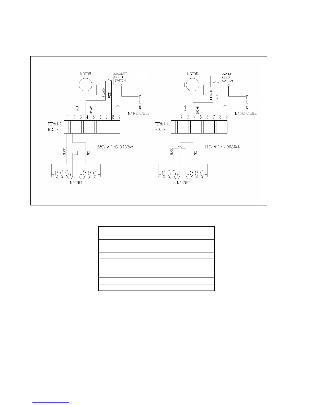
8) WIRING DIAGRAM
No Function
Wire Colour
1 Magnet 1
- (110v & 230v Magnet)
Black
2 Magnet 2+ (110v & 230v Magnet)
Red
3 Motor Blue
4 Magnet reed switch
Black
5 Motor Brown
6 N/C
7 Mains (
Neutral
) Blue
8 Magnet reed switch
Red
9 Mains (
Live)
Brown
Page 11
Issue 5 Original version Nov 2014
11
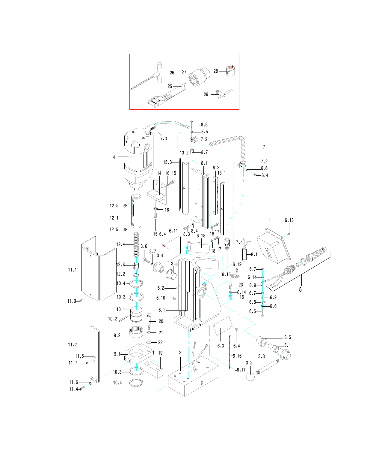
9) EXPLODED DIAGRAM OF MACHINE
Page 12
Issue 5 Original version Nov 2014
12
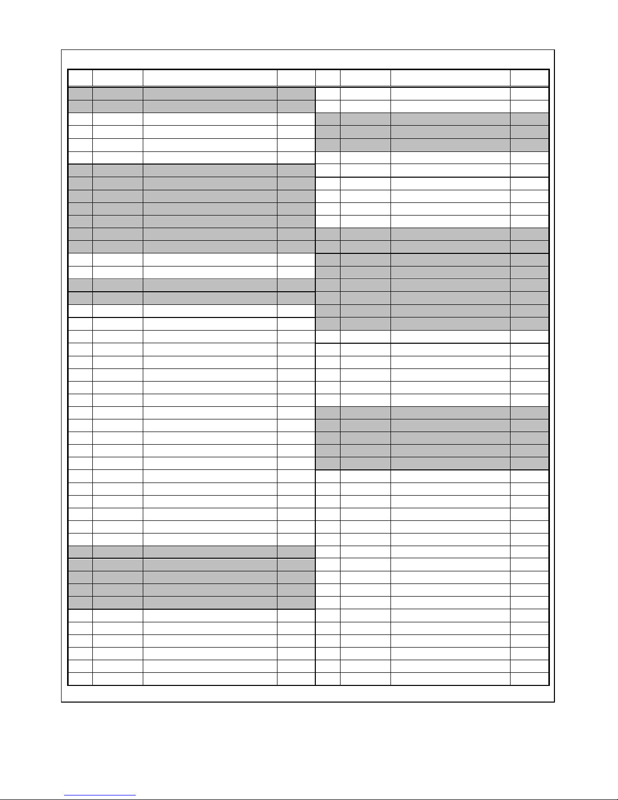
Component parts list for Rotabroach Puma CM/300/1 & CM/300/3 From serial number 107621
Item Part number Discription Quantity Item Part number Discription Quantity
1 RD23094
Control panel assembly 110v.
1
8.6 RD43093
Screw. 1
1 RD23095
Control panel assembly 230v.
1
8.7 RD43116
Spacer block 1
2 RD23081
Magnet assembly 110v.
1
9 RD23014
Bearing bracket assembly.
1
2 RD23083
Magnet assembly 230v.
1
9.1 RD33099
Bearing bracket. 1
2.1 RD45606
Protection Switch
1
9.2 RD4518
Bearing 1
3 RD23008
Capstan assembly.
1
10 RD23015
Arbor sleeve assembly.
1
3.1 RD33088
Capstan spindle. 1
9 RD23014
Bearing bracket assembly. 1
3.2 RD43091
Capstan ball. 3
10.1 RD33100
Ejector sleeve. 1
3.3 RD33089
Capstan arm. 3
10.2 RA353
Pin. 1
3.4 RD33090
Capstan pinion sleeve. 1
10.3 RD4519
Thrust washer. 2
3.5 RD33092
Bearing. 2
10.4 RD43084
Circlip. 2
3.6 RD4098
M6 Socket head cap screw. 1
11 RD23016
Guard assembly.
1
3.7 RD4207
M6 Spring washer. 1
11.1 RD33101
Guard. 1
4 RD23064
Motor & Gearbox assy 110v. 1
11.2 RD33102
Guard bracket 1
4 RD23065
Motor & Gearbox assy 230v. 1
11.3 RD43092
Screw. 2
5 RD23009
Mains cable assembly 110v. 1
11.4 RD43096
Screw. 2
5 RD23012
Mains cable assembly 230v. 1
11.5 RD43097
Ball plunger 2
6 RD23003
Housing assembly. 1
11.6 RD43098
Shakeproof washer. 1
6.1 RD33094
Housing. 1
11.7 RD4252
M3 screw 1
6.2 RD4102
Tension pin. 2
12 RD23019
Arbor assembly.
1
6.3 RD33077
Logo plate. 1
12.1 RD33137
Arbor spindle. 1
6.4 RD4077
Screw. 4
12.2 RD4056
Circlip. 1
6.5 RD43093
Screw. 1
12.3 RA354
Button. 1
6.6 RD4069
Shakeproof washer. 1
12.4 RD3319
Spring. 1
6.7 RD4068
Nut. 2
12.5 RD4066
M8 Socket screw. 4
6.8 RD43094
Earth tag. 1
13 RD23018
Gib strip assembly
1
6.9 RD4070
Washer. 1
13.1 RD33103
Fixed gib strip 1
6.10 RD4312
Screw. 4
13.2 RD33104
Adjustable gib strip 1
6.11 RD4302
Information plate. 1
13.3 RD33105
Gib support strip 1
6.13 RD4077
M4 x 8 Pan head 1
14 RD33106
Motor support bracket. 1
6.14 RD43113
M4 spring washer 1
15 RD4157
M6 Socket head screw. 2
6.15 RD43117
Mains cable clamp 1
16 RD4096
M6 Shakeproof washer. 2
6.16 RD33145
Depth Guage 1
17 RD4091
M5 Socket head screw. 4
6.17 RD33146
Rivet 1
18 RD4092
M5 Shakeproof washer. 4
6.18 RD33144
Rubber Handle 1
19 RD33107
Bearing spacer. 1
6.19 RD43093
Screw 2
20 RD4319
M8 Bolt 2
7 RD23010
Motor supply cable assembly.
1
21 RD4079
M8 Shakeproof washer 2
7.1 RD33095
Cable assembly. 1
22 RD4078
M8 Washer 2
7.2 RD43095
cable clip. 2
23 RD4098
M6 Socket head cap screw. 2
7.3 RD43346
Motor cable elbow 1
24 RD4095
M6 Washer. 2
7.4 RD43112
Connector 1
25 RD4329
Safety Strap 1
8 RD23004
Slide assembly
1
26 RD4088
4mm Allen Key 1
8.1 RD33096
Slide. 1
27 RD43099
13mm Drill Chuck 1
8.2 RD33097
Rack. 1
28 RD33153
Drill Chuck Adaptor 1
8.3 RD4325
M5 socket head screw. 2
29 RD33154
Drill Chuck Key 1
8.4 RD4092
M5 Shakeproof washer. 2
8.5 RD4069
Shakeproof washer. 1
Page 13
Issue 5 Original version Nov 2014
13
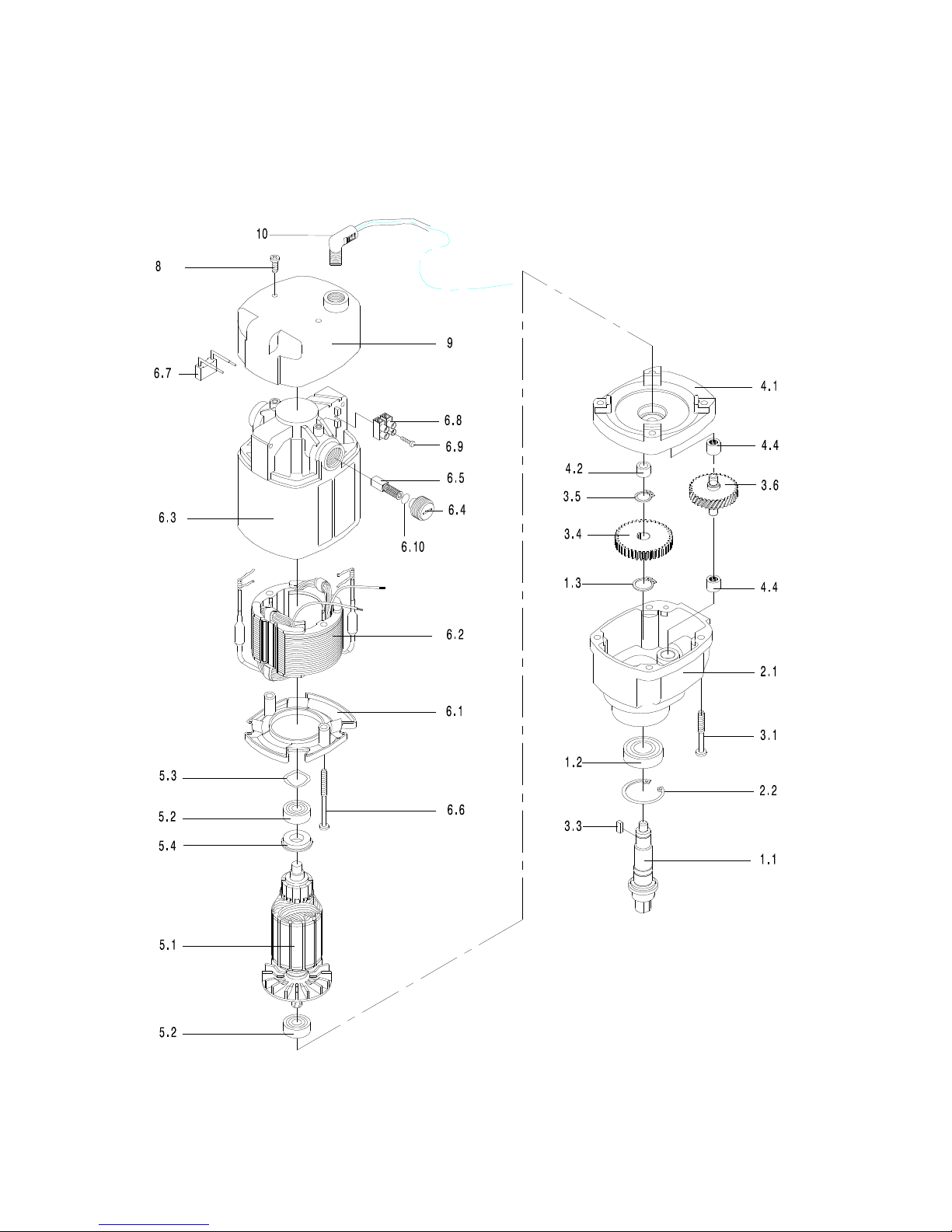
10) EXPLODED DIAGRAM OF MOTOR AND GEARBOX
(From serial No 106991 and greater)
Page 14
Issue 5 Original version Nov 2014
14
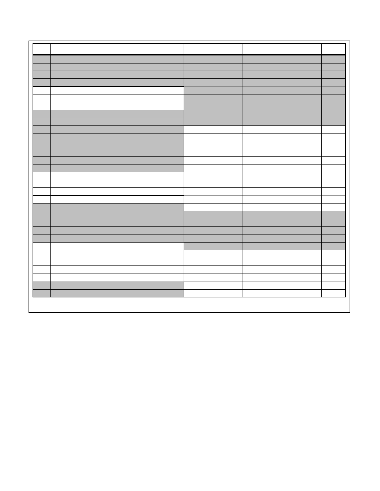
Item
Part
Number Description Qty Item
Part
Number Description Qty
1 RD23020 Output shaft assembly. 1
6.2 RD33111 Field coil 110v. 1
1.1* RD33139 Output shaft. 1 6.3 RD33085/B Motor casing. 1
1.2 RM304210 Bearing. 1 6.4 RD33086 Brush end cap. 1
1.3 RM22876 Circlip. 1 6.5 RM297640 Carbon Brush assy 110v. 2
2 RD23024/B Gearbox Housing assembly. 1
6.6 RD43089 Screw. 2
2.1 RD33081/B Gearbox Housing. 1 6.7 RD43118 Capacitor 1
2.2 RM22876 Circlip. 1 6.8 RD43119 Terminal 1
3 RD23001/B Gearbox assembly. 1
6.9 RD43120 Screw. 4
1 RD23020 Output shaft assembly. 1 6.10 RD43121 Brush cover spring 1
2 RD23006/B Gearbox Housing assembly. 1
6 RD23023/B Motor case assembly 230v 1
3.1 RD43085 Screw. 4 6.1 RD33084 Field coil baffle. 1
3.3* RD33128 Key 1 6.2 RD33113 Field coil 230v. 1
3.4 RD33082 Final drive gear. 1 6.3 RD33085/B Motor casing. 1
3.5 RD43087 Circlip 1 6.4 RD33086 Brush end cap. 2
3.6 RD33083 Intermediate gear. 1 6.5 RM297630 Carbon Brush assy 230v. 2
4 RD23007/B Inner Gear plate assembly. 1
6.6 RD43089 Screw. 2
4.1 RD23007 Inner Gear plate. 1 6.7 RD43118 Capacitor 1
4.2 RD43088 Ph Bz Bearing. 1 6.8 RD43119 Terminal 1
4.4 RM22880 Needle Bearing. 2 6.9 RD43120 Screw. 4
5 RD23011 Armature assembly 110v 1
6.10 RD43121 Brush cover spring 2
5.1 RD33091 Armature 110v 1
7 RD23031 Motor assembly 110v 1
5.2 RM17134 Bearing. 2 5 RD23011 Armature assembly 110v 1
5.3 RD43122 Washer 3 6 RD23021/B Motor case assembly 110v 1
5.4 RD43123 Dust proof Ring 1 9 RD33087/B Motor end cap 1
5 RD23013 Armature assembly 230v 1
8 RD43090 Screw. 2
5.1 RD33093 Armature 230v 1
7 RD23033 Motor assembly 230v 1
5.2 RM17134 Bearing. 2 5 RD23013 Armature assembly 230v 1
5.3 RD43122 Washer 3 6 RD33113 Field coil 230v. 1
5.4 RD43123 Dust proof ring 1 8 RD43090 Screw. 2
6 RD23021/B Motor case assembly 110v 1
9 RD33087 Motor End Cap 1
6.1 RD33084 Field coil baffle. 1 10 RD43346 Motor Cable elbow 1
Page 15
Issue 5 Original version Nov 2014
15
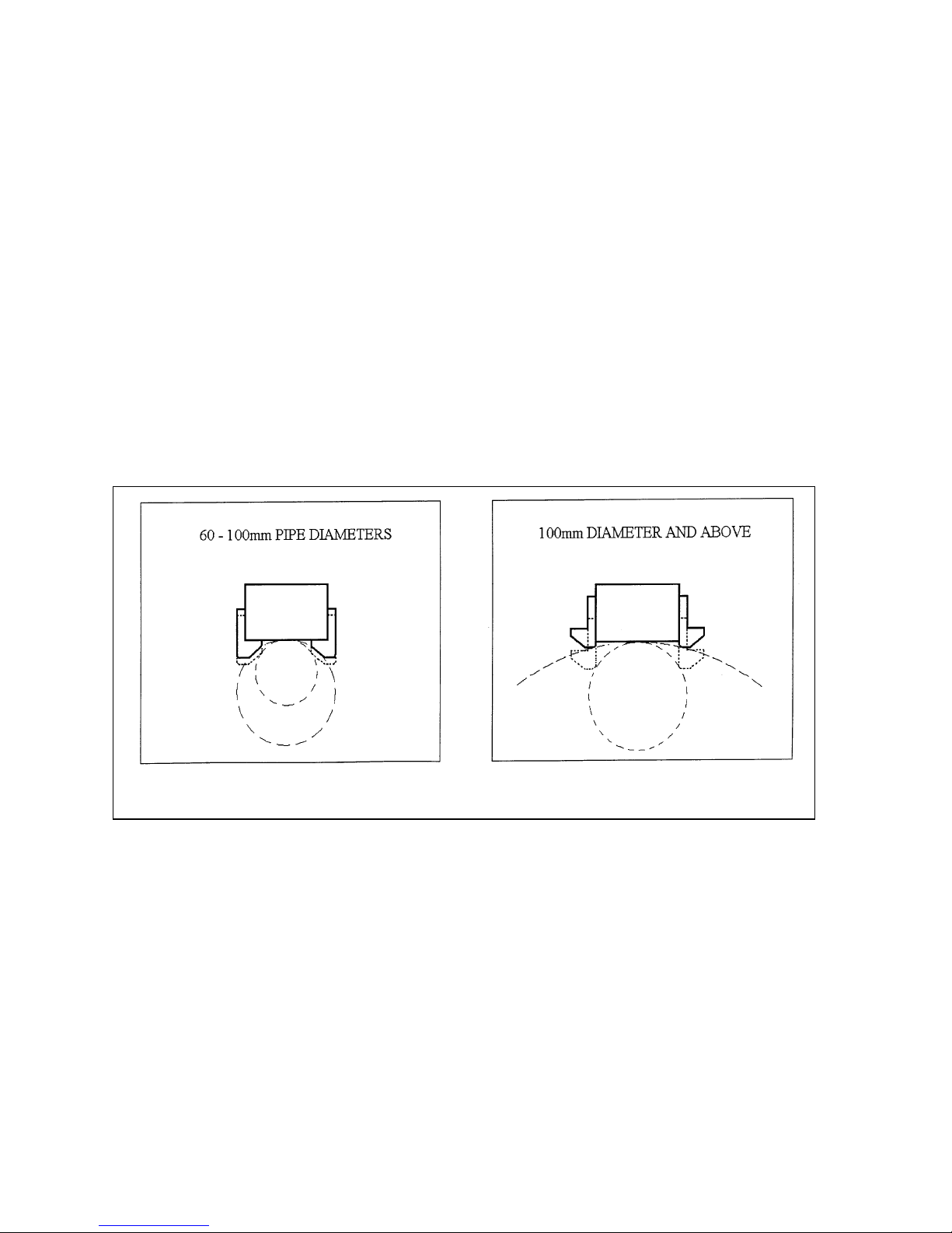
11) PIPE ADAPTOR KIT RD2311
FITTING INSTRUCTIONS
•
Dependent upon the size of the pipe to be cut (see illustrations) attach adjustable angle
plates RD3328 with cap screws RD4325 and washers RD4205 (4 off each) to the magnet
sides. Do not tighten.
•
Locate the machine on the centreline pipe taking care that the magnet is in line with the
longitudinal axis of the pipe.
•
Switch on the magnet and move the sliding plates down to the outside diameter of the
pipe. Tighten the screws on both sides by hand then check once again that the full length
of the moving plates is touching the pipe at the front and back, fasten the plate securely.
Feed the safety strap through the lugs at the front of the housing, around the pipe and pull
tight.
•
When cutting the hole DO NOT use excessive pressure but rather let the cutter ease into
the cutting surface.
Page 16

Issue 5 Original version Nov 2014
16
12) CHUCK CONVERSION
• To remove the arbour lay the machine on its side.
• Unscrew the two grub screws at the top of the arbor
• Some early machines will only have spanner flats on the arbor.
• When the arbor has become detached from the spindle this can then be removed
• Remove the arbour support bracket and guard with the arbour retained.
• Mount the chuck using the chuck adaptor RD33153.
• Replacing the chuck is the reverse sequence.
13) MAINTENANCE
In order to ‘get the best life’ out of your Rotabroach™ machine always keep in good working
order.
A number of items must always be checked on Rotabroach™ machines.
Always before starting any job make sure the machine is in good working order and that there
are no damaged or loose parts. Any loose parts must be tightened.
Before proceeding with any maintenance work be certain that the power supply is
disconnected.
Description
Every operation
1 week
1 Month
Visual check of
machine for damage
X
Operation of machine
X
Check brush wear
X
Check magnetic base
X
Check alignment of
the machine
X
Check grea
se X
Check Armature
X
Visually check the machine for damage.
Machine must be checked before operation for any signs of damage that will affect the
operation of the machine. Particular notice must be taken of the mains cable, if the machine
appears to be damaged it should not be used failure to do so may cause injury or death.
Check operation of the machine.
The machines operation must be checked to ensure that all components are working correctly.
Page 17

Issue 5 Original version Nov 2014
17
Machine Brushes - should be checked to make sure there is no abnormal wear present this
should be checked at least once a week if used frequently. If the brush has worn more than 2/3
the original length the brushes should be changed. Failure to do so may cause damage to the
machine.
Magnetic base – before every operation the magnetic base should be checked to make sure
that the base is flat and there is no damage present. An uneven magnet base will cause the
magnet not to hold as efficiently and may cause injury to the operator.
Adjustment of slide and bearing bracket Alignment.
An essential requirement of the machine is that the slide can move in a smooth and controlled
manner, free of lateral movement and vibration.
This situation can be maintained by periodic adjustment of the slide and is accomplished in the
following manner:
1. Place the machine in an upright position and, by means of the capstan, raise the slide to
its highest position. Clean the brass gib strips and apply a small amount of light machine
oil to the wear surfaces.
2. Now lower the slide back to its lowest position. Bring the slide into the centre of the
dovetail slide housing and loosen screws thus allowing free movement of the arbor
support bracket.
3. Commencing with the middle screws, gently feed in all the screws until slight resistance
is encountered.
4. Operate the slide up and down a few times to test the movement and make any further
necessary adjustments. Try to ensure that all the screws are exerting a uniform pressure
on the slide from top to bottom. A perfectly adjusted slide will operate freely up and
down without any sideways movement.
5. Now raise the slide to its highest position. Slightly undo the arbor bearing bracket and,
using fingers only, tighten the screws.
6. Place the machine on a steel plate, connect to supply and switch on magnet. Start up the
motor. If the arbor is incorrectly aligned, the arbor support bracket will be seen to
oscillate. Make any necessary further adjustments to the bracket to ensure correct
alignment of the spindle and finally tighten the screws using a spanner. Lastly tighten
the arbor bearing bracket.
Check machines grease.
The gearbox grease should be checked once a month to ensure all moving components are
covered to prevent wear. The grease should be changed at least once a year to ensure you gain
the best from the machine.
Check Armature of the machine.
This should be checked at least 1 per month to check that there are visual signs of damage to
the body or to the commutator. Some signs of wear will be seen on the commutator over a
period of time this is normal as this is the part that comes in contact with the brushes but any
signs of abnormal damage and the part should be replaced.
Page 18

Issue 5 Original version Nov 2014
18
14) TROUBLE SHOOTING
Magnet and motor do not function
-
The magnet switch is not connected to the power supply
- Damaged or defective wiring
- Defective fuse
- Defective magnet switch
- Defective Control Unit
- Defective power supply
Magnet does function, the motor does not
-
Damaged or defective wiring
- Carbon brushes are stuck or worn out
- Defective magnet switch
- Defective On / off switch
- Defective Control Unit
- Defective armature and/or field
- Defective magnet protective switch
Magnet does not function, the motor does
-
Defective magnet
- Defective Control Unit
Hole cutters break quickly, holes are bigger
than the hole cutter
- Play in the guide
- Bent spindle
- Defective Magnet causing movement
- Shaft extending from the motor is bent
- Uneven work surface causing lack of magnetic adhesion.
- Bent pilot
Motor running roughly and/or seizing up
-
Bent spindle
- Shaft extending from the motor is bent
- Triangular guide not mounted straight
- Dirt between spindle and triangular guide
Motor making a rattling sound
-
Gear bearing (bottom of the armature) worn out
- Gear(s) worn out
- No grease in gear box
Motor
humming, big sparks and motor has no
force
- Armature burned
- Field burned
- Carbon brushes worn out
Motor does not start or fails.
- Damaged or defective wiring
- Dirt in sensor of Speed Control Unit
- Defective Speed Control Unit
- Defective speed control or its wiring
- Defective or loose magnet on top of armature
- Damaged or defective brushes
Guiding takes a great deal of effort
-
Guide is set too tight
- Guide is dry
- Guide/gear- rack/rotation system dirty or damaged
Insufficient magnetic forc
e - Damaged or defective wiring
- Bottom of magnet not clean and dry
- Bottom of magnet not flat
- Work piece is not bare metal
- Work piece is not flat
- Work piece is too thin less than 10mm
- Defective Control Unit
- Defective magnet
Motor only runs at
maximum rpm
-
Defective speed switch
- Damaged / defective wiring
- Defective Control Unit
Frame under voltage
-
Damaged / defective wiring
- Defective magnet
- Motor seriously dirty
Fuse blows when magnet switch is turned on
-
Damaged or defective wi
ring
- Wrong value fuse
- Defective magnet switch
- Defective Control Unit
- Defective magnet
Fuse blows when motor is started up
-
Damaged or defective wiring
- Wrong value fuse
- Motor running roughly
- Defective Armature and / or Field
- Carbon brushes worn out
- Defective Control Unit
Rotation system free stroke too long
-
Loose or defective gear
-
rack
- Defective rotation system
Page 19
Issue 5 Original version Nov 2014
19
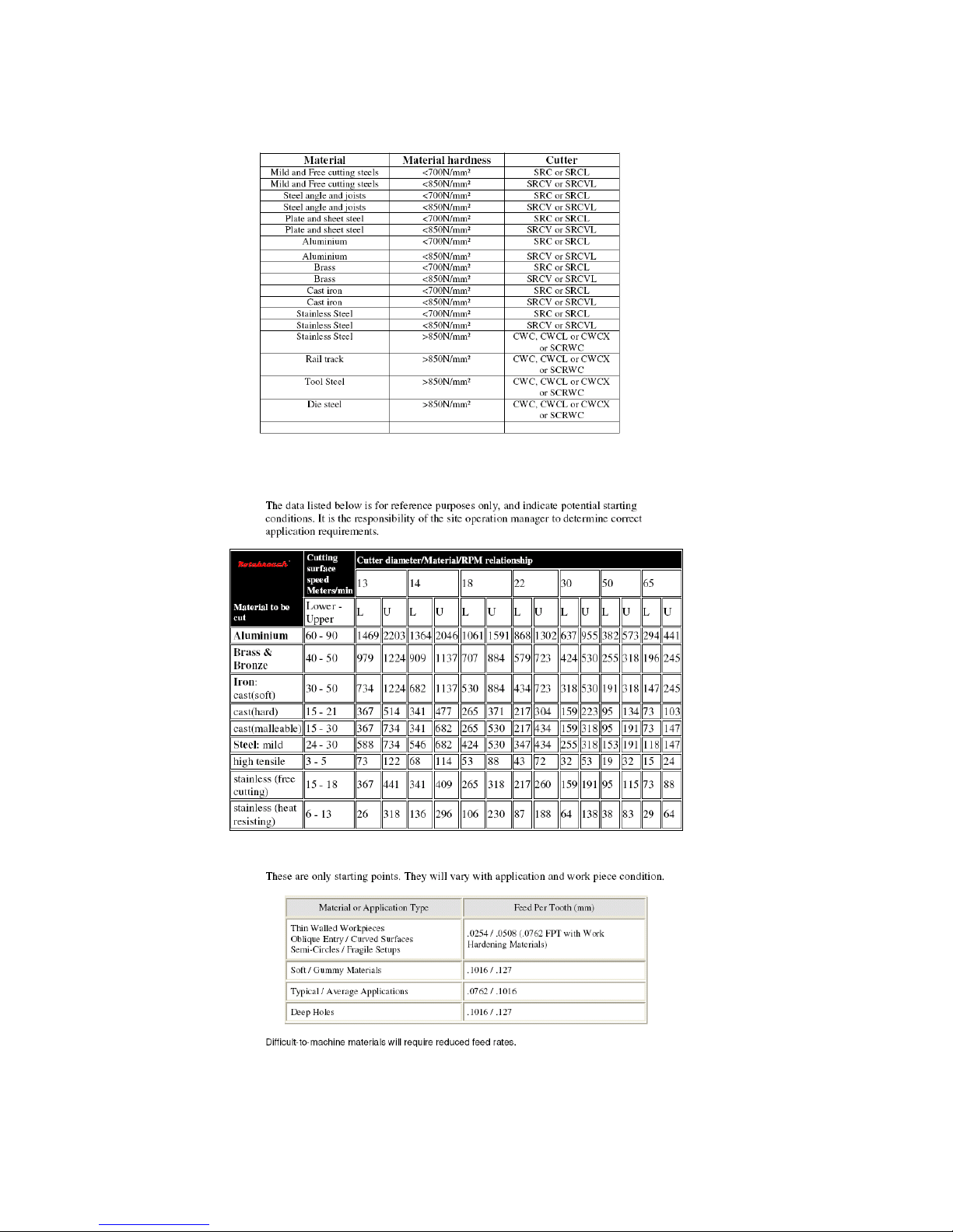
15) CUTTER SELECTION, SPEEDS AND FEEDS
Page 20

Issue 5 Original version Nov 2014
20
WARRANTY STATEMENT
Rotabroach™ warrants its machines to be free from faulty materials, or workmanship under normal use for a period of 6
months from initial date of purchase and 90 days for all other parts (excluding cutters), provided that the warranty
registration card (or online registration) has been completed and returned to Rotabroach™, or its designated distributor
within a period of (30) days from the purchase date, failure to do so will void the warranty. If the stated is adhered to
Rotabroach™ will repair or replace (at its option) without charge any faulty items returned.
This Warranty does not cover:
1. Components that are subject to natural wear and tear caused by the use in accordance with the operators instructions
2. Defects in the tool caused by non-compliance with the operating instructions, improper use, abnormal environment conditions, inappropriate
operating conditions overload or insufficie nt servicing or maintenance.
3. Defects caused by using accessories, components or spare parts other than original Rotabroach™ parts.
4. Tools to which changes or additions have been made.
5. Electrical components are subject to manufacturer’s warranty.
Your online registration can be submitted on www.rotabroach.co.uk
The warranty claim must be lodged within the warranty period. This requires the submission or sending of the complete
tool in question with the original sales receipt which must indicate the purchase date of the product. A complaint form
must also be submitted prior to the return.
This can be found online at www.rotabroach.co.uk Failure to complete this form will result in the delay of your claim.
All goods returned defective must be returned pre-paid to Rotabroach™, in no event shall Rotabroach™ be liable for
subsequent direct, or indirect loss or damage.
THIS WARRANTY IS IN LIEU OF ANY OTHER WARRANTY, (EXPRESSED OR IMPLIED) INCLUDING ANY WARRANTY OF
MECHANTABLITY OR FITNESS FOR A PARTICULAR PURPOSE. ROTABROACH™ RESERVE THE RIGHT TO MAKE
IMPROVEMENTS AND MODIFICATIONS TO DESIGN WITHOUT PRIOR NOTICE
Known and Trusted Worldwide for Quality, Performance and Reliability
 Loading...