

Page 1
Console
Consola
Console
Konsole
Console
Console
9
16
23
30
37
44
Gebrauchsanweisung
Mode d’emploi
Istruzioni per l’uso
Instrucciones de uso
Gebruiksaanwijzing
Kontakt den nærmeste Boston Scientific
kundeserviceafdeling, hvis en dansk kopi af
brugsanvisningerne ønskes. Spørg efter reservedel nr.:
90185046-02 Rev. B
ЕрйкпйнщнЮуфе ме фп гсбцеЯп еохрзсЭфзузт фзт
Boston Scientific бн пй ПдзгЯет ЧсЮузт брбйфеЯфбй нб
еЯнбй уфб ЕллзнйкЬ. ЖзфЮуфе фпн бсйимь бнфбллбкфйкпэ:
90185046-03 Rev. B
Entrar em contacto com o escritório para atendimento de
clientes da Boston Scientific se uma cópia das instruções
para utilização em português for necessária. Pedir pela
brochura número: 90185046-04 Rev. B
Kontakta Boston Scientific kundtjänst om ni behöver ett
exemplar av en svensk bruksanvisning. Fråga efter del
nummer: 90185046-05 Rev. B
3
Directions for Use
TM
Page 2

2
Page 3
Description
The Rotablator Rotational Angioplasty System is a catheter-based angioplasty
device utilizing a diamond-coated elliptical burr at the tip of a flexible drive
shaft. Tracking coaxially over a guide wire and rotating at up to 190,000 RPM,
the burr ablates plaque into fine particles that are disposed of by the body’s
reticuloendothelial system. The three main components included in the system
are the guide wire, control console system, and the advancer/catheter.
The Rotablator Console monitors and controls the rotational speed of the burr
and provides the operator with performance information throughout the
procedure. In the control console, the gas is filtered and then regulated by a
fixed-pressure regulator. The resultant pressure is gated by a pilot-actuated
valve, and gas flow is automatically adjusted by a proportional pneumatic valve
in order to maintain proper Rotablator System operating speed. The gas then
enters the gas turbine, and after expanding in the turbine, is exhausted at the
bottom of the Rotablator Rotational Angioplasty System advancer. Compressed
gas is also supplied to the foot pedal through a triple hose. When the foot pedal
is depressed, the gas is returned to the console, where it activates the pilot
valve, permitting flow of regulated compressed gas to the Rotablator Rotational
Angioplasty System advancer via the front panel turbine connector. With this
pilot valve arrangement, the gas flow to the Rotablator Rotational Angioplasty
System advancer cannot be throttled by using the foot pedal.
Intended Use
The Rotablator Console is intended for use with the Rotablator Rotational
Angioplasty System. Refer to guide wire and advancer package inserts for
specific information on the use of these components.
Restrictions, Warnings and Precautions
Restrictions
Caution: Federal (USA) law restricts this device to sale by or on the
order of a physician. For coronary use, federal (USA) law further
restricts this device to a physician trained and/or experienced in coronary
balloon angioplasty. Governing law outside the USA restricts this device to sale
by or on the order of a physician.
Warnings
• Never use oxygen as the propellant for the Rotablator Rotational
Angioplasty System. Never connect the regulator to an oxygen cylinder.
Oxygen combined with oil or other combustibles in the system can result in
an explosion.
• The use of accessories, transducers and cables other than those specified,
with the exception of transducers and cables sold by the manufacturer of the
Rotablator System as replacement parts for internal components, may result
in increased emissions or decreased immunity of the Rotablator System.
• The Rotablator System should not be used adjacent to or stacked with other
equipment and that if adjacent or stacked use is necessary, the Rotablator
System should be observed to verify normal operation in the configuration
in which it will be used.
• This device is not to be used in the presence of flammable anesthetics.
• If a hissing noise is detected from the console, check to make sure that the
pressure of the gas supplied to the air or nitrogen connector does not exceed
758.4 kPa (110 psi). The console is equipped with a pressure relief valve to
protect against excessive inlet pressure. Do NOT operate the Rotablator
Console with gas pressures in excess of 758.4 kPa (110 psi), as a gas hose
may burst.
• If patient defibrillation becomes necessary, the physician should take the
appropriate measures to protect himself against electrocution from the
defibrillator.
• Do not modify or repair. Modification or repair of the instrument by a
person other than an authorized Boston Scientific representative may
compromise the integrity of the device and/or lead to device failure
which, in turn, may result in patient injury or death. Boston Scientific
assumes no liability with respect to any instrument which has been
modified or repaired by a person other than an authorized Boston
Scientific representative and makes no warranties, express or implied,
including but not limited to merchantability or fitness for a particular
purpose, with respect to such instruments. If repair is needed, call your
Boston Scientific representative.
Precautions
• Care must be taken not to spill saline or other fluids on the console. Saline
spilled in the console may result in corrosion or electrical hazard.
• User should take precautions when using the console in conjunction with
other medical electrical equipment, as electromagnetic interference between
the equipment may affect the performance of the console or other devices.
The console complies with IEC 60601-1-2 regulations for radiation of and
immunity from electromagnetic energy.
• The Rotablator Console needs special precautions regarding EMC and needs
to be installed and put into service according to the EMC information
provided in Appendix D.
• Portable and mobile RF communications equipment can affect the
Rotablator Console.
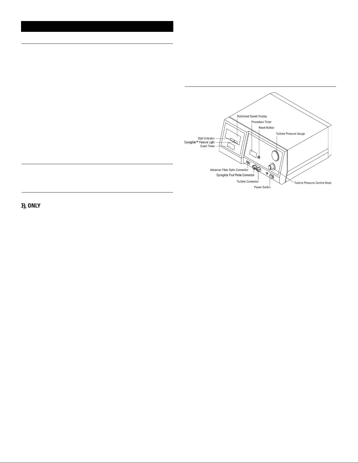
Description of the Rotablator Console
Figure 1
Control Console Front Panel
The symbols used on the console are listed in Appendix A. The main features
and functions of the console shown in Figure 1 are described below.
Front Panel
• Power Switch: Power is supplied to the console when the switch is in the
depressed position. The push button power switch is located in the lower
right corner of the front panel. The green light to the left of the switch
illuminates to indicate that the power has been turned on.
• Turbine Pressure Control Knob: The knob located above the power
switch is used to adjust the gas pressure to the turbine and consequently, the
rotational speed. Turning the knob clockwise increases the turbine pressure
(speed) as indicated on the turbine pressure gauge. Counterclockwise
rotation decreases the turbine pressure (speed).
• Turbine Pressure Gauge: Located above the turbine pressure control knob,
the pressure gauge displays the pressure of the compressed gas being
supplied to the advancer gas turbine. Generally the greater the gas pressure
to the gas turbine, the higher the rotational speed. The pressure should not
be allowed to exceed 482.6 kPa (70 psi) during normal operation. Flow
restrictions have been incorporated into the pneumatic system to prevent the
delivery of excessive energy to the advancer. For additional information on
operating range, accuracy and precision, see Table 1.
• Rotational Speed Display (Tachometer): The rotational speed display
located in the upper left corner of the console indicates the speed in RPM of
the burr and gas turbine. When the gas turbine is not operating, the display
is blank. When the foot pedal is depressed, the rotational speed is shown on
the rotational speed display. For additional information on operating range,
accuracy and precision, see Table 1.
• STALL Light: The STALL light is located directly below the rotational
speed display, and is visible only when illuminated. If the rotational speed of
an advancer falls below 15,000 RPM for more than 0.5 second, the red
STALL light is illuminated and delivery of compressed gas to the advancer
is discontinued. A stall condition may also be detected if the fiber optic
connection is not properly engaged. Stall detection is a safety feature
designed to discontinue delivery of compressed gas to the advancer in the
event of excessive mechanical loading or incorrect connection of the fiber
optic. Releasing the foot pedal will clear the stall condition and extinguish
the STALL light.
3
Rotablator™ Rotational Angioplasty System
Page 4

• DYNAGLIDE™ Feature Light: The DYNAGLIDE Feature light is
located adjacent to the STALL light, and is visible only when illuminated
indicating that the Dynaglide Feature is activated. The Dynaglide Feature
provides a controlled low speed rotation (approximately 50,000-90,000
RPM) of the Rotablator™ Burr for use during intraprocedure exchange of
Rotablator Rotational Angioplasty System advancer or catheter. The
Dynaglide Foot Pedal button is used to turn the Dynaglide Feature on or off.
• Event Timer: Located below the tachometer, the event timer records how
long the foot pedal has been continuously depressed with the air turbine and
burr spinning. When the foot pedal is released, the timer continues to
display the previous event time. Depressing the foot pedal resets and restarts
the timer. For additional information on operating range, accuracy and
precision, see Table 1.
• Procedure Timer: The procedure time is the sum of the individual event
times and indicates the total time the burr has been spinning during the
procedure. For additional information on operating range, accuracy and
precision, see Table 1.
Table 1
• Reset Button: Pushing the reset button resets the event and procedure
timers to zero.
• Turbine Connector: The gas line connector on the right-hand side receives
the advancer gas hose and supplies filtered, regulated compressed gas to the
advancer when the foot pedal is depressed.
• Dynaglide Foot Pedal Connector: The gas line connector on the left-hand
side receives the Dynaglide Foot Pedal pink hose, and is used to activate or
deactivate the Dynaglide Feature mode of operation.
• Fiber Optic Tachometer Cable Connector: These two female connectors
receive the mating male connectors from the fiber optic tachometer cable.
The orientation of the cable to the female connector is not important. The
fiber optic tachometer cable carries light pulses which the console uses to
determine the rotational speed of the gas turbine and burr.
Rear Panel
• Line Cord: This cable plugs into a conventional 100-120 V a.c. or
220-240 V a.c. receptacle (as indicated on the name plate located on the
rear of the console) and provides power to the console. In Germany, line
cord connections must be to a VDE 0107 compliant installation. The ground
wire of the line cord is internally connected to the console chassis.
• Fuses: The fuses protect the console’s electrical components in the event of
a serious electrical fault. If a fuse should fail, refer to Appendix B for
replacement instructions.
• Potential Equalization Connector: Located to the left of the fuse, the
potential equalization connector is provided to allow potential equalization
between various hospital electrical instruments. In Germany, the potential
equalization connections must be made to a VDE 0107 compliant installation.
•
Compressed Gas Inlet: This male connector, located in the top center of the
rear panel, mates to the corresponding connector on the supply line from the
compressed gas source. Pressure at this inlet should always be between 620.5
and 758.4 kPa (90 and 110 psi) with a minimum flow capacity of 140 l/min
(5 standard cubic feet per minute (scfm)). Pressure will be reduced by the
console to operating limits. An internal pressure-relief valve protects against
input pressures in excess of 792.9 kPa (115 psi) and creates a loud hissing
noise in the console when the pressure exceeds 792.9 kPa (115 psi).
• Dynaglide Foot Pedal Connectors: These two connectors receive the mating
pair of connectors from the Dynaglide Foot Pedal. The green hose connects to
the right-hand connector and the blue hose to the left-hand connector.
Other
• Dynaglide Foot Pedal: The foot pedal is used as an on/off control for the
advancer gas turbine. The foot pedal is also fitted with a valve which vents
any compressed gas in the foot pedal hose when the pedal is released,
permitting the burr to stop rapidly. The foot pedal is mounted in a protective
shroud which inhibits accidental actuation.
• The Dynaglide Foot Pedal button located on the right side of the foot pedal
housing is used as an on/off control for the Dynaglide Feature mode of
operation. When the Dynaglide Feature is on, the green DYNAGLIDE
Feature light is illuminated on the console front panel.
Assembly and Setup of the Rotablator Console
The recommended control console system, illustrated in Figure 2, consists of an air
or nitrogen pressure regulator mounted on a compressed gas cylinder, connected to
the Rotablator Console via a supply hose (provided with the console). The gas
cylinder is shown for illustration only, and is not of the recommended size. Gas
cylinders must be properly secured per standard procedures.
Note: It may also be possible to operate this system from a hospital (house) gas
system, as discussed in Appendix C. The Rotablator Console is not suitable for
use with in-hospital (house) compressed gas lines in Germany due to pressure
and flow incompatibilities, unless connections are made in accordance with
DIN 13 260.
Figure 2
Control Console System
To put the Rotablator Console into service, proceed as follows:
WARNING NEVER use oxygen as the propellant for the Rotablator
Rotational Angioplasty System. NEVER connect the
regulator to an oxygen cylinder. Oxygen combined with oil or
other combustibles in the system can result in an explosion.
WARNING This device is not to be used in the presence of
flammable anesthetics.
1. Procure a compressed gas cylinder containing either compressed air or nitrogen.
In Germany, only compressed air may be used, gas cylinder fittings must be
according to DIN 477 Teil 1 (Druckluft), and compressed gas cylinders must
be approved by the German government (Bauartzugelassen). A cylinder
capacity of at least 2250 l (79.46 standard cubic feet) is recommended, and
will provide approximately 20 minutes of service with the Rotablator
Rotational Angioplasty System advancer running at full speed. Larger
cylinders may be used. A fully charged spare cylinder should always be
available.
2. Secure the compressed gas cylinder in accordance with hospital procedures.
3. Obtain a cylinder regulator (relieving type is preferred) capable of
delivering at least 140 l/min (5 scfm) at 620.5-758.4 kPa (90-110 psi).
Make certain that the cylinder regulator fitting is compatible with the gas
cylinder being used. In Germany, only compressed air may be used, gas
cylinder fittings must be according to DIN 477 Teil 1 (Druckluft), and
compressed gas cylinders must be approved by the German government
(Bauartzugelassen).
4. Connect the supply hose gas coupling (provided with the Rotablator
Console) to the outlet port of the cylinder regulator.
Unless local government regulations require otherwise, the gas coupling
is configured with .6 cm (¼”) MNPT threads. Verify the type of gas
coupling provided with the Rotablator Console prior to procuring a
cylinder regulator.
If necessary, use suitable adapters to make the connection. In some
countries, the regulator end of the gas supply hose has a permanently
attached warning tag to remind users not to connect it to oxygen sources.
Do NOT remove this tag.
4
Display Operating Range Accuracy Precision
Turbine Pressure Gauge 0-689.5 kPa or 0-100 psi ± 5% 6.9 kPa or 1 psi
Rotational Speed Display 0-250,000 RPM ± 1.5% 1,000 RPM
Event Timer 00:00-59:59 ± 0.1% 1 second
Procedure Timer 00:00-59:59 ± 0.1% 1 second
Cylinder Regulator
Advancer Hose
Cylinder
Saline Infusion Port
Advancer
Catheter
Dynaglide Foot Pedal
Supply Hose
Console
Turbine Connector
Fiber Optic Connector
Foot
Pedal
Hose
Page 5

5
5. Remove the cylinder cap and attach the regulator, tightening the
cylinder fitting firmly.
The regulator should be adjusted so that the outlet pressure is in the range
620.5-758.4 kPa (90-110 psi).
6. Connect the supply hose to the inlet connector on the back of the console.
In most countries, the inlet connector is marked AIR OR NITROGEN. In
Germany, the inlet connector is marked ‘Druckluft’. Verify that the
compressed gas being placed into service is in accordance with the inlet
connector marking.
7. Connect the foot pedal to the console by first locating the three
connectors at the end of the foot pedal triple hose.
Insert the green hose connector in the right-hand and the blue hose
connector in the left-hand mating receptacles on the rear of the Rotablator™
Console. These receptacles are labeled FOOT PEDAL or marked with a foot
pedal symbol. Connect the pink hose connector to the left-hand connector
on the front panel.
8. Connect the power cord to a properly rated hospital grade receptacle
(as indicated on the nameplate located on the rear of the console).
In Germany, power connections must be made to a VDE 0107 compliant
installation, and the potential equalization stud must be connected.
9. Open the compressed gas cylinder valve, or line valve if running on
house air (see Appendix C), to supply compressed gas to the console.
Note that the cylinder regulator gauge indicates the pressure of the gas
remaining in the cylinder. The regulator should be adjusted so that it never
supplies more than 758.4 kPa (110 psi) to the console, and no less than
620.5 kPa (90 psi). Do not initiate the procedure if less than 3,447 kPa
(500 psi) of gas remains in the tank.
WARNING If a hissing noise is detected from the console, check to make
sure that the gas pressure supplied to the air or nitrogen
connector does not exceed 758.4 kPa (110 psi). The console
is equipped with a pressure relief valve to protect against
excessive inlet pressure. Do NOT operate the Rotablator
Console with gas pressures in excess of 758.4 kPa (110 psi),
as a compressed gas hose may burst.
10.Push the console power switch and confirm that the green light
illuminates indicating power is on.
The Rotablator Console is now ready for use. Console placement,
ventilation, splash protection and cleaning instructions may be found below
in the section entitled: “Operation, Cleaning and Disposal Instructions.”
Operation, Cleaning and Disposal Instructions
1. Ventilation
The Rotablator Console uses natural convection cooling to maintain the
proper operating temperature for internal components. Cooling vents are
located on the bottom and rear of the console enclosure. In order to ensure
proper ventilation of the console, it must be placed on a hard, flat surface
with a minimum of 2.5 cm (1”) clearance maintained around all sides and
bottom of the enclosure. Do not set on drapes or bedding.
2. Splash
The Rotablator Console is designed to be placed outside of the sterile field.
Care should be taken to protect the console from splash and ingress of
liquids which may cause damage to internal components.
3. Cleaning
The Rotablator Console and Dynaglide™ Foot Pedal should be cleaned
regularly by wiping with a soft cloth dampened with a mixture of water
and mild detergent. Never immerse in fluids. The use of solvents or
abrasive cleaners may cause damage to the plastic parts of the console and
should be avoided.
4. Disposal
The user should follow local and national regulations for disposal of
electronics when disposing of this unit. The console contains no batteries or
heavy metals.
References
For coronary use, please refer to the Rotablator Rotational Angioplasty System
physician training program course materials for a listing of publications, or
contact your local sales representative. Additional articles, including
publications on the use of the Rotablator Rotational Angioplasty System in the
peripheral vasculature are available upon request. Please contact your local
sales representative to obtain a listing.
The symbols shown below may be present when required by specific safety
testing agencies such as Underwriters Laboratories (UL), Canadian Standards
Association (CSA), etc.
Dangerous voltage. To reduce risk of electric shock, do NOT
remove cover. Refer servicing to qualified service personnel.
Potential equalization connector. Provides means of achieving potential
equalization between hospital instruments. In Germany, connection
must be to a VDE 0107 compliant installation.
Indicates that a fire hazard may exist if fuses are not replaced as
marked.
Indicates type CF equipment.
Attention! Consult Accompanying Documents.
Console power is OFF when the power switch is in
the OUT position.
Console power is ON when the power switch is in the IN position.
Rotational Speed. Displays speed of the burr in RPM.
Event Time. Displays the length of time the foot pedal
has been continuously depressed.
Procedure Time. Displays the sum of the individual event times.
Reset. Resets the event and procedure timers to zero.
Turbine Pressure. Displays the pressure of the compressed
gas being supplied to the advancer gas turbine.
Turbine pressure increases with clockwise rotation.
Fiber optic connector.
Turbine. Connector for the advancer gas hose.
Compressed Gas Inlet. Connector for the supply line
from the compressed gas source.
Foot pedal connectors.
Proper disposal of electronic equipment is required according to
EN directive 2002/96/EC, Waste of Electrical and Electronic
Equipment (WEEE).
Contents of Package.
Appendix A - Symbol Translation Key
Page 6

6
Product Number.
The product has been tested for compliance with the applicable
requirements of UL 60601-1:2003. Safety approval for the US has
been granted by Underwriters Laboratories.
The product has been tested for compliance with the applicable
requirements of CAN/CSA C22.2 No. 601.1. Safety approval for
Canada has been granted by CSA.
Electrical safety testing was performed by TUV
Rheinland.
Danger - Explosion Hazard.
Do not use in the presence of flammable anesthetics.
Store within the given relative humidity upper and lower
limitations.
Technical Specifications
Electrical Selectable 100-120 V a.c. or 220-240 V a.c.
Specifications: Voltage:
Frequency: 50-60 Hz
Power: 70 VA
Fuses: 2 x F2.0A, 250V
Pneumatic Input Gas: Compressed Air or Nitrogen
Specifications: Pressure: 620.5-758.4 kPa (90-110 psi)
Flow: Minimum, 140 l/min (5 scfm) at rated pressure.
Operating Ventilation: Minimum 2.5 cm (1”) clearance on all sides,
Conditions: with console on a hard flat surface.
Temperature: +10º to +40ºC
Humidity: 10% to 90% non condensing
Storage Temperature: -30º to +60ºC
Conditions: Humidity: 10% to 95% non condensing
Safety Agency Underwriters Laboratory (UL) Classified to UL60601-1/Can/
Registration: CSA C22.2 No. 601.1 Medical Device Class I per UL 60601-1
National Australia Testing Agency (NATA) Type CF
equipment (IEC 601).
TUV certifications to IEC 601, EN550011, Class B and
EN60601-1-2.
Quarterly Inspections
These inspections should be performed once per quarter. If console fails any of
the inspections listed below, contact your Customer Service representative.
1. Check the physical condition of the power cable, strain relief, and plug.
Make sure that there are no frayed ends on the power cable connector, the
strain relief is attached, the plug has no bent prongs, and the ground prong
in the plug is present and secure. Verify that there are no unacceptable
scratches or punctures on the exterior of the AC cord set.
2. Check for loose or missing screws, sharp edges, or loose connectors.
By hand, check the console pneumatic connectors and verify that they are
not loose. Verify that all screws are in place on covers. Hold console in both
hands and shake in two different directions to verify that there is no loose
hardware inside the console.
3. Perform an external visual inspection for mechanical damage.
Verify that there are no unacceptable chips, dents, scratches, or marks on
the console enclosure or foot pedal. Verify that the knobs are secured
properly and are not loose. Tighten any loose knobs. Make sure that the
pneumatic connectors are in working order, not stuck open, and are tight
against the console.
4. Check the front panel indicators.
With the console connected to AC power and compressed gas, cycle the
Power switch to apply power to the console and verify that:
a) The green Power LED illuminates.
b) The EVENT TIME display reads 00:00.
c) The PROCEDURE TIME display reads 00:00.
d) The RPM display is blank.
e) The STALL display is blank.
5. Check the operation of the turbine pressure gauge.
Connect the console to AC power and compressed gas. Starting with the
SPEED ADJUST knob fully counterclockwise, verify that clockwise rotation
of the SPEED ADJUST knob results in an increased reading on the console
TURBINE PRESSURE gauge.
6. Check the operation of the DYNAGLIDE™ Foot Pedal display.
With the console connected to AC power and compressed gas, and with the
Dynaglide Foot Pedal connected, turn on the unit, cycle the DYNAGLIDE
Feature button on the foot pedal, and verify that the DYNAGLIDE Feature
indicator illuminates and goes blank.
7. Check the operation of the STALL display.
Without connecting the advancer (i.e., no fiber optic connector plugged in),
activate the foot pedal and check for stall light illumination. Verify that the
stall light goes blank when foot pedal is released.
Service Information
Fuse: In the event of a fuse failure, turn off the power and unplug the line cord
from the power outlet. The power cord may also be unplugged from the rear of
the console to improve fuse access. Using a tool such as a screwdriver, remove
the fuse drawer by depressing the locking tab. See Figure 3 below.
Figure 3
Fuse Replacement
Replace both fuses with the same type and rating as specified on the rear of
the console. Reinsert the fuse drawer until the locking tab snaps into place.
Reconnect the power cord and restore power to the console. If a fuse fails
again, disconnect all power to the console and contact your Customer Service
representative.
All other service must be performed by Boston Scientific Corporation personnel.
Field repair, other than the console’s external fuse replacement, voids all
warranties and may not be performed without express authorization from
Customer Service.
Note: This appendix does NOT apply to TUV Rotablator™ Consoles.
The Rotablator Rotational Angioplasty System is designed to be operated from
compressed gas cylinders via a cylinder regulator. However, if a house air or
nitrogen system is available, the control console can be supplied directly,
eliminating the need for a cylinder and cylinder regulator. The requirements are
as follows:
1. The compressed gas must be air or nitrogen only.
2. The gas must be clean, dry, and oil free.
3. The gas pressure must be between 620.5 kPa (90 psi) and 758.4 kPa
(110 psi) at the inlet to the control console.
4. The system must be capable of supplying gas at a rate of 140 l/min
(5 scfm) or more.
Appendix B - Service and Maintenance Information
Appendix C - Running the System
From Low Pressure (House) Lines
Power Cord
Receptacle
Locking T
Fuse Drawer
Page 7

7
An adapter fitting is available for the Rotablator™ Console. This fitting has a
female quick-connect on one end and .6 cm (¼”) MNPT threads on the other.
The .6 cm (¼”) MNPT end is a standard .6 cm (¼”) pipe male fitting and will
readily fit most gas handling equipment or connectors on the house lines. The
quick-connect mates directly to the connector on the end of the supply hose
which normally would attach to a regulator.
Appendix D - Electronic and
Electromagnetic Guidance
Guidance and manufacturer’s declaration - electronic emissions
The Rotablator System is intended for use in the electromagnetic environment specified below. The customer or the user of the Rotablator System should assure that it
is used in such an environment.
Emission Test Compliance Electromagnetic Environment - Guidance
RF emissions
CISPR 11
Group 1 The Rotablator System uses RF energy only for its internal function. Therefore, its RF emissions
are very low and are not likely to cause any interference in nearby electronic equipment.
RF emissions
CISPR 11
Class A The Rotablator System is suitable for use in all establishments other than domestic and those
directly connected to the public low-voltage power supply network that supplies buildings used
for domestic purposes.
Harmonic emissions
IEC 61000-3-2
Class A
Voltage fluctuations / flicker emissions
IEC 61000-3-3
Complies
Guidance and manufacturer’s declaration - electromagnetic immunity
The Rotablator System is intended for use in the electromagnetic environment specified below. The customer or the user of the Rotablator System should assure that it
is used in such an environment.
Immunity Test IEC 60601
Test Level
Compliance Level Electromagnetic Environment - Guidance
Electrostatic discharge (ESD)
IEC 61000-4-2
+
6 kV contact
+ 8 kV air
+
6 kV contact
+ 8 kV air
Floors should be wood, concrete or ceramic tile. If floors are covered
with synthetic material, the relative humidity should be at least 30%.
Electrical fast transient / burst
IEC 61000-4-4
+
2 kV for power supply lines
+ 1 kV for input / output lines
+
2 kV for power supply lines
+ 1 kV for input / output lines
Mains power quality should be that of a typical commercial or
hospital environment.
Surge
IEC 61000-4-5
+
1 kV differential mode
+ 2 kV common mode
+
1 kV differential mode
+ 2 kV common mode
Mains power quality should be that of a typical commercial or
hospital environment.
Voltage dips, short
interruptions and voltage
variations on power supply
input lines
IEC 61000-4-11
<5% UT(>95% dip in UT)
for 0,5 cycle
40% UT(60% dip in UT)
for 5 cycles
70% UT(30% dip in UT)
for 25 cycles
<5% UT(>95% dip in UT)
for 5 seconds
<5% UT(>95% dip in UT)
for 0,5 cycle
40% UT(60% dip in UT)
for 5 cycles
70% UT(30% dip in UT)
for 25 cycles
<5% UT(>95% dip in UT)
for 5 seconds
Mains power quality should be that of a typical commercial or
hospital environment. If the user of the Rotablator System requires
continued operation during power mains interruptions, it is
recommended that the Rotablator System be powered from an
uninterruptible power supply or a battery.
Power frequency (50/60 Hz)
magnetic field
IEC 61000-4-8
3 A/m 3 A/m Power frequency magnetic fields should be at levels characteristic of
a typical location in a typical commercial or hospital environment.
NOTE: UTis the a.c. mains voltage prior to application of the test level.
Page 8

8
Guidance and manufacturer’s declaration - electromagnetic immunity
The Rotablator™ System is intended for use in the electromagnetic environment specified below. The customer or the user of the Rotablator System should assure
that it is used in such an environment.
Immunity Test IEC 60601
Test Level
Compliance Level Electromagnetic Environment - Guidance
Conducted RF
IEC 61000-4-6
Radiated RF
IEC 61000-4-3
3 Vrms
150 kHz to 80 MHz
3 V/m
80 MHz to 2,5 GHz
3 V
3 V/m
Portable and mobile RF communications equipment should be used no closer to
any part of the Rotablator System, including cables, than the recommended
separation distance calculated from the equation applicable to the frequency of the
transmitter.
Recommended separation distance
d = 1,2 √P
d = 1,2 √P 80 MHz to 800 MHz
d = 2,3 √P 800 MHz to 2,5 GHz
where P is the maximum output power rating of the transmitter in watts (W)
according to the transmitter manufacturer and d is the recommended separation
distance in meters (m).
Field strengths from fixed RF transmitters, as determined by an electromagnetic
site surveya, should be less than the compliance level in each frequency range.
b
Interference may occur in the vicinity of equipment marked with the following
symbol:
NOTE 1: At 80 MHz and 800 MHz, the higher frequency range applies.
NOTE 2: These guidelines may not apply in all situations. Electromagnetic propagation is affected by absorption and reflection from structures, objects and people.
a
Field strengths from fixed transmitters, such as base stations for radio (cellular/cordless) telephones and land mobile radios, amateur radio, AM and FM radio
broadcast and TV broadcast cannot be predicted theoretically with accuracy. To assess the electromagnetic environment due to fixed RF transmitters, an
electromagnetic site survey should be considered. If the measured field strength in the location in which the Rotablator System is used exceeds the applicable RF
compliance level above, the Rotablator System should be observed to verify normal operation. If abnormal performance is observed, additional measures may be
necessary, such as re-orienting or relocating the Rotablator System.
b
Over the frequency range 150 kHz to 80 MHz, field strengths should be less than 3 V/m.
Recommended separation distances between portable and mobile RF communications equipment and the Rotablator System
The Rotablator System is intended for use in an electromagnetic environment in which radiated RF disturbances are controlled. The customer or the user of the
Rotablator System can help prevent electromagnetic interference by maintaining a minimum distance between portable and mobile RF communications equipment
(transmitters) and the Rotablator System as recommended below, according to the maximum output power of the communications equipment.
Rate Maximum Output Power of
Transmitter
W
Separation Distance According to Frequency of Transmitter
m
150 kHz to 80 MHz
d = 1,2 √P
80 MHz to 800 MHz
d = 1,2 √P
800 MHz to 2,5 GHz
d = 2,3 √P
0,01 0,12 0,12 0,23
0,1 0,38 0,38 0,73
1 1,2 1,2 2,3
10 3,8 3,8 7,3
100 12 12 23
For transmitters rated at a maximum output power not listed above, the recommended separation distance d in meters (m) can be estimated using the equation
applicable to the frequency of the transmitter, where P is the maximum output power rating of the transmitter in watts (W) according to the transmitter manufacturer.
NOTE 1: At 80 MHz and 800 MHz, the separation distance for the higher frequency range applies.
NOTE 2: These guidelines may not apply in all situations. Electromagnetic propagation is affected by absorption and reflection from structures, objects and people.
Warranty
Boston Scientific Corporation (BSC) warrants that reasonable care has been
used in the design and manufacture of this instrument. This warranty is in lieu
of and excludes all other warranties not expressly set forth herein, whether
express or implied by operation of law or otherwise, including, but not
limited to, any implied warranties of merchantability or fitness for a
particular purpose. Handling, storage, cleaning and sterilization of this
instrument as well as other factors relating to the patient, diagnosis, treatment,
surgical procedures and other matters beyond BSC’s control directly affect the
instrument and the results obtained from its use. BSC’s obligation under this
warranty is limited to the repair or replacement of this instrument and BSC
shall not be liable for any incidental or consequential loss, damage or expense
directly or indirectly arising from the use of this instrument. BSC neither
assumes, nor authorizes any other person to assume for it, any other or
additional liability or responsibility in connection with this instrument.
Page 9

Boston Scientific International S.A.
55 avenue des Champs Pierreux
TSA 51101
92729 NANTERRE CEDEX
FRANCE
Boston Scientific Corporation
One Boston Scientific Place
Natick, MA 01760-1537
USA
USA Customer Service 888-272-1001
© 2007 Boston Scientific Corporation or its affiliates.
All rights reserved.
90185046-01
 Loading...