

Page 1
Form #5299, Rev. B, 07-27-12
Page 2

Parking Sensor System
CONTENT
INTRODUCTION
………………
1
INSTALLATION
MODEL NUMBER
………………
1
INSTALLATION TOOLS
………………
7
FEATURES
………………
1
WHERE TO INSTALL
………………
8
TECHNICAL DATA
………………
2
INSTALLATION PROCEDURE
………………
8
PRODUCT COMPOSITIO N
………………
3
SENSOR INSTALLATION
………………
9
HOW TO USE
POWERING UP
………………
11
SYSTEM STARTUP
………………
3
PRECAUTIONS
………………
12
DIAGNOSTICS
………………
3
TEST THE SYSTEM
WARNING MODE
………………
4
TEST SUBJECTS
………………
12
WARNING UNIT
………………
5
TEST METHODS
………………
13
ABOUT DETECTION
………………
5
DISCLAIMER
………………
13
PRECAUTIONS
………………
7
TROUBLESHOOTING
………………
14
WARRANTY CARD
………………
16
Page 3

1
Parking Sensor System
● INTRODUCTION
The Park-Pro HD is a superior reverse parking system
that provides a visual and audible alarm when close to
large objects to aid the driver while parking in reverse.
Read t his manual thoroughly before installation and
operation of t he system. Please pay attention to all of t he
precautions and instructions listed in this manual.
Installation by trained professionals is recommended.
T his manual describes the functions, installation, use and
precautions of the reverse parking syst em.
Designs and spec ifications are subject to change without
prior notice and the diagrams or figures in this manua l may
differ slightly in appearance from the actual product.
T his devic e is only a parking aid an d should never be
solely relied upon for safely backing up a vehic le. The use of
this system should never replac e normal operational and
safety prec autions needed for reversing a vehic le. Always use
caution during any vehicle operation.
Model number
The model number and system description/features are
listed on the box.
F eatures
High sensitivity: Able t o quic kly detect large obstacles (c ar,
wall, pole, etc.) up to 2.5M (98”) behind the vehicle.
Min. det ection distance: 22cm (approx. 9”).
Wide detection angle wit h minima l blind areas.
Adjustable alarm volume: high and low. Audible alarm
start s approximately 1.7M (67”) behind the vehic le.
Diagnostic functions monitor and alert you of inoperable
sensors.
S mall, unobtrusive sensor design and shape.
Reliable performa nc e, design and use of high-quality
components ensure consistent operation.
Ultrasonic sensing using triangulation detection
technology to consistently and acc urately detect object with
fewer false alarms.
Page 4
2
Parking Sensor System
Aut omatic bypass of trailer tow hitc h or rear mounted
spare tire.
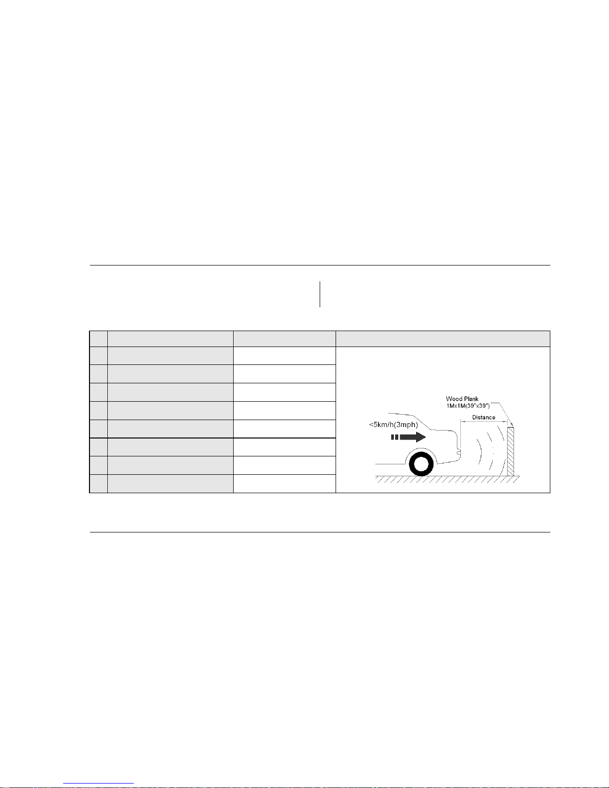
Diagram-1: TECHNICAL DATA OF REVERSE PARKING SYSTEM
NO
ITEM
Rating
REMARKS
1
Working Voltage (VDC)
10.5~16 (Rated Voltage=12)
1. Alarm dista nce is the detected distance from sensor to
obstacle during operation at 25C.
2. The d istance resu lts from de tecting a square wood plank of
1mx1m (3 9”x39”).
2
Rated Current (max.)
200mA
3
Alarm Dista nce: m (in.)
0.22 (9”)~2.5 (98”)
4
Blind Area: m (in.) at 25C
<0.22 (9”)
5
Detection Tolerance: m (in .) at 25C
±0.03 (1”)
6
Alarm Volume
105dB
7
Working Temperature(C)
-40~+75
8
Storage Temperature(C)
-40~+90
Page 5
3
Parking Sensor System
● PRODUCT COMPOSITION
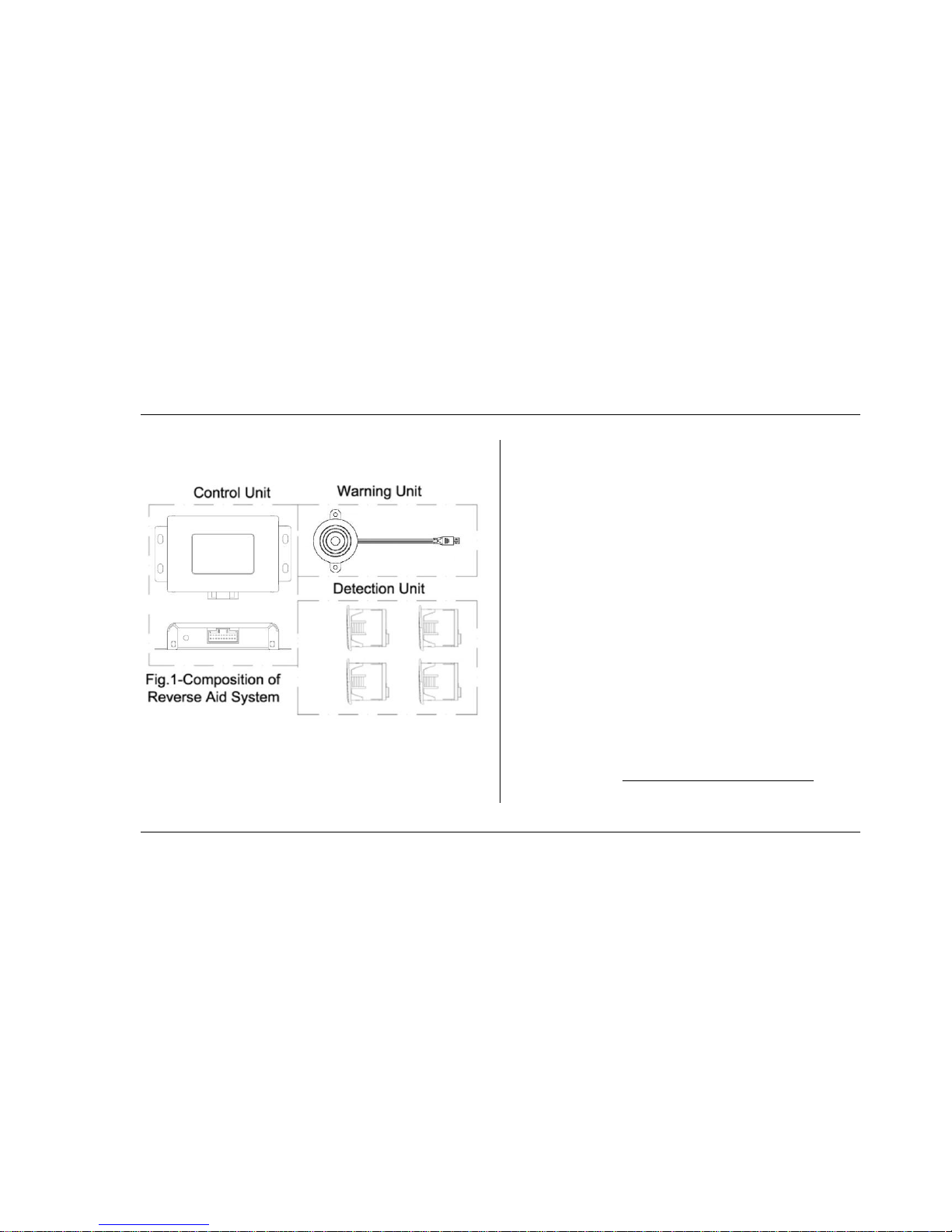
The system consists of 3 basic components (see Fig.1):
Electronic Control Unit (ECU)
Detection Un its - Ultrasonic Sensors
Warning Unit
When the vehic le is placed in reverse, t he warning unit
warns drivers of obstacles by sounding an alarm.
Note: The warning unit has a High/Low switch for volume
control.
● HOW TO USE
System Startup
Reverse Parking System
T he system is fully automatic . It is active only when the
vehicle is placed in reverse.
At system power-up (Vehicle ignition on, in reverse), you
will hear a short , half-second ‘beep’.
Diagnostics
After the system is turned on, the Park- Pro HD will go into
a self diagnostic mode for three seconds.
If, after t hree seconds a sensor malfunc tion is detected,
the warning unit will warn you of a fault. The syst em will st ill
operate, but may not function normally. (See
troubleshooting section for explanation of diagnostics
Page 6
4
Parking Sensor System
function.)
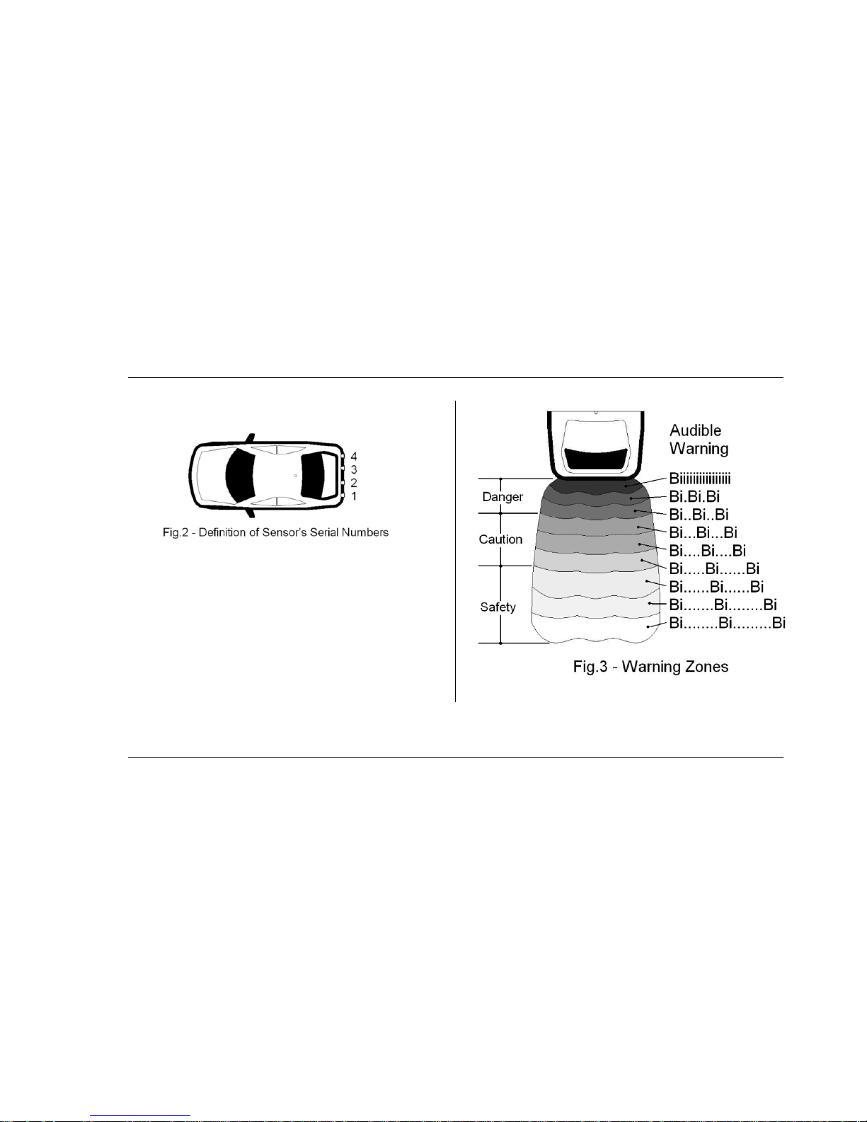
Note: Sensors must be installed in order of serial number. I f not, the
diagnostic function may refe rence the wrong sensor. See Fig.2.
Warning Mode
See Fig.3 for the three detection zones.
Audible Warning: System beeps when an obstacle
appears within t he Warning zones, shown in Diagram 2.
Page 7
5
Parking Sensor System
Diagram-2
AUDIB LE WARNING MO DE FOR REAR DETECTION
WARNING
ZONE
DISTANCE
(D)
AUDIBLE WARNING
MODE
Danger Zone
M(in.)
00"<D≤09"
Beep(Bi)
09"<D≤12"
Bi. Bi.Bi
12"<D≤20"
Bi. .Bi. .Bi
Caution Zone
M(in.)
20"<D≤28"
Bi… Bi…Bi
28"<D≤36"
Bi….Bi…. Bi
36"<D≤44"
Bi…..Bi…..Bi
Safety Zone
M(in.)
44"<D≤68"
Bi…...Bi…...Bi
68"<D≤76"
Bi…….Bi…....Bi
76"<D≤98"
Bi……..Bi……..Bi
Outside
98"<D
-
Remark: When obstacles appear behind the 2 rear side sensors (serial
numbers 1 and 4), syste m doesn’t beep unles s the obstacles are within
the Caution and Danger zones.
Warning Unit
This unit warns you with a built-in buzzer, enabling you t o
know the warning zone and distance to the obstacle.
About detection
Obstacle detection may vary due to object size, shape,
density and environmental conditions. It is rec ommended to
thoroughly check the system sensitivity before use.
An unusual reflection angle of obst acles may c ause an
incorrect or unusual detection warning.
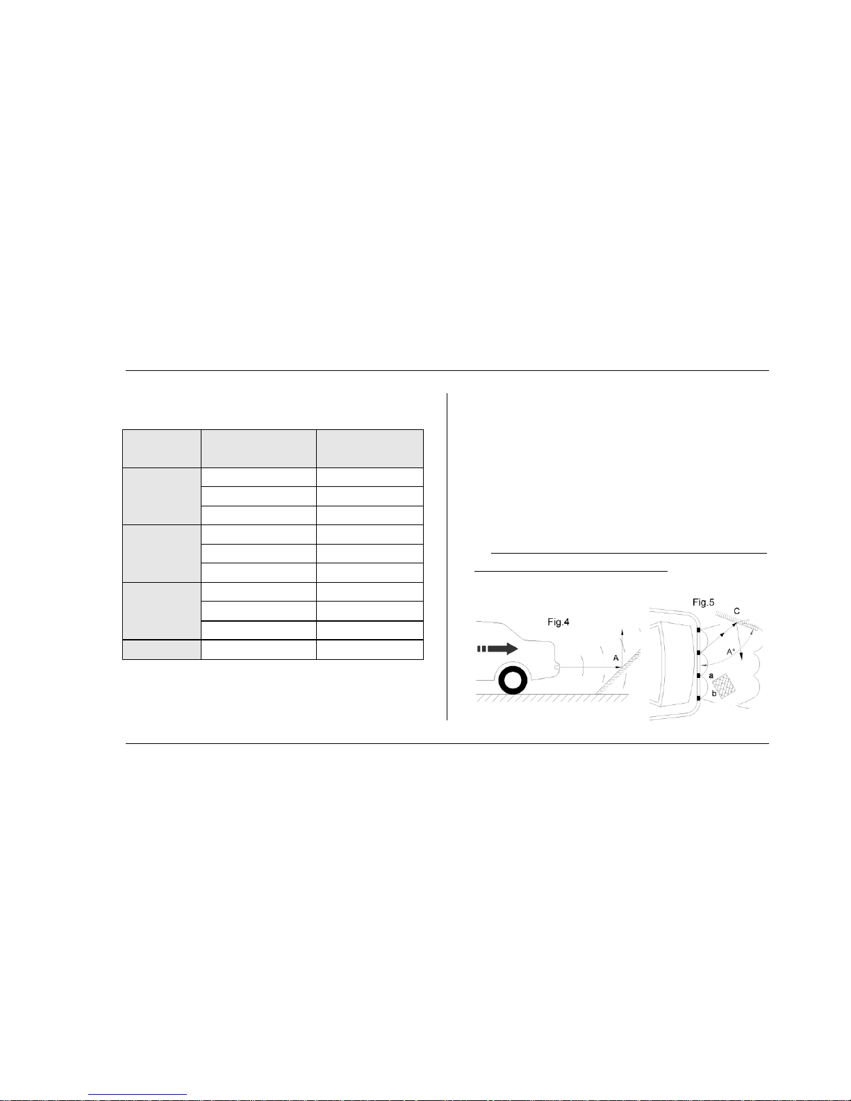
Refer to Fig. 4 below: Po int A may not be detected due to unsatisfactory
reflection angle.
Page 8
6
Parking Sensor System
In Fig.5, detec tion may be variable due to object size, height and
density. Angled surfaces may give false distance measurements.
Various surface angles may be detected at varying distances on the
display.
Low obstacle standing before a tall one
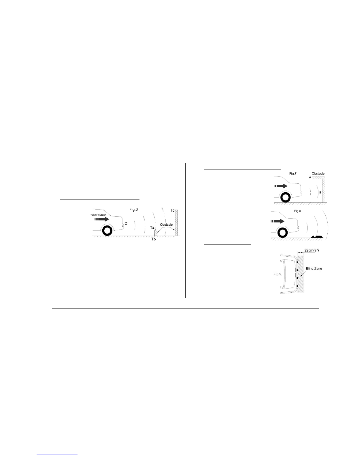
As shown in Fig.6,
although
Obstacle T
a-b
is
lower than the
sensors, Part Tb
will be detected
and warned first. As you approach these obstacles, the warnings may
vary in intensity.
Unusual condition of obstacle
Due to va rying height, size, clothing type (absorption o f signal), etc., A
PERSON MAY NOT BE DE TECTED . This device is only a parking aid
and should never be solely relied upon for sa fely backing up a vehicle.
Always use caution during any vehicle operation.
Obst acles outside the detecting range
In Fig.7, Surface B will be detected, while
Surface A may never be detected.
Unusual road surface condition
When road s urfaces are rough, the
system ma y output a warning signal.
See Fig.8.
Obst acles in blind zone
The blind zone covers a range o f 22cm
(9”) behind the vehicle. Obstacles in the
blind zone will never be detected.
Therefore, it is norm al if the warning unit
provides inc orrect detection results. S ee
Fig.9.
Page 9
7
Parking Sensor System
Precautions
When this system is working, the reverse speed must be
under 5km/h (3 mph).
Keep sensors clean. Remove dirt, ice or snow for proper
operation.
Make sure that sensors are mount ed securely in the
correct posit ion.
When sensors are found defective, they should be
replaced immediately.
After installation, t esting should be conducted to verify
proper operation before use.
● INSTALLATION
It is recommen ded this system be installed by a trained
installation professional.
Installation Tools
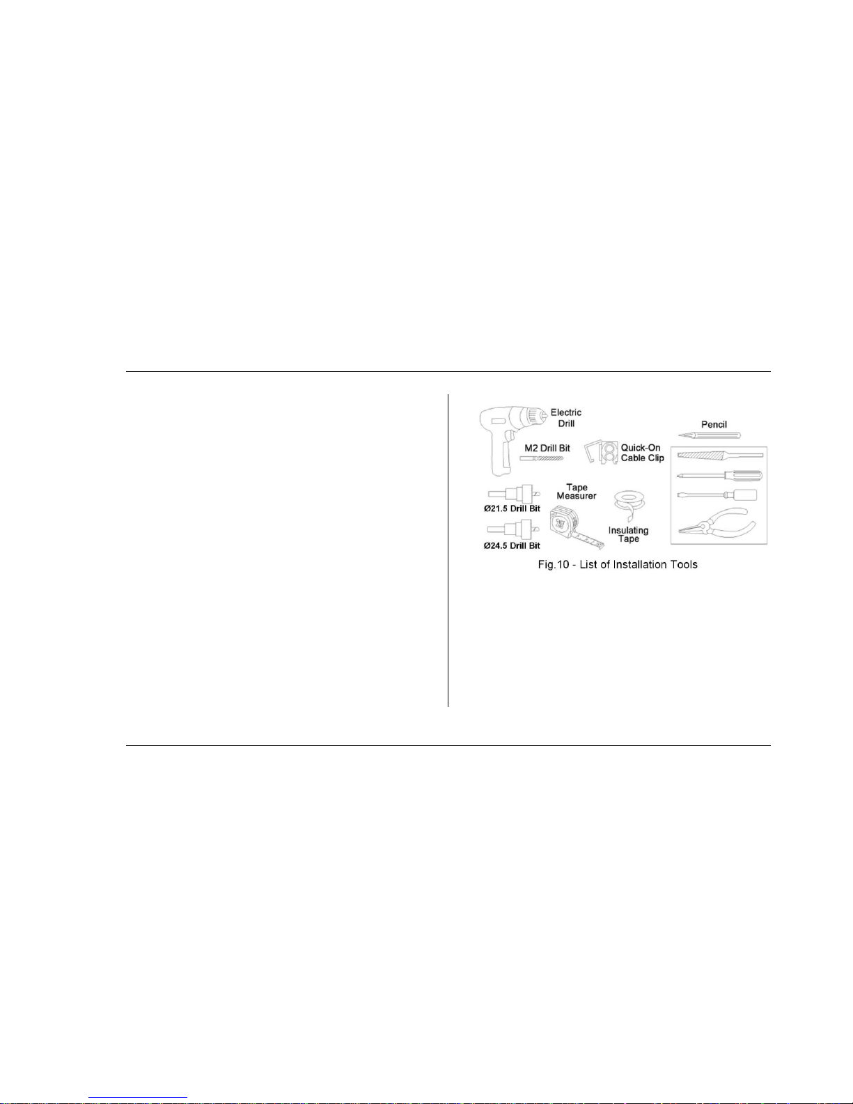
The tools listed in Fig.10 are required for installation.
· The k it inc ludes two drill bits, ele ctrical connectors, double-sided
adhesive tape . In addition a file, flat head screwdriver, Philips head
screwdriver and a pair of pliers will be required.
Page 10
8
Parking Sensor System
Where to Install
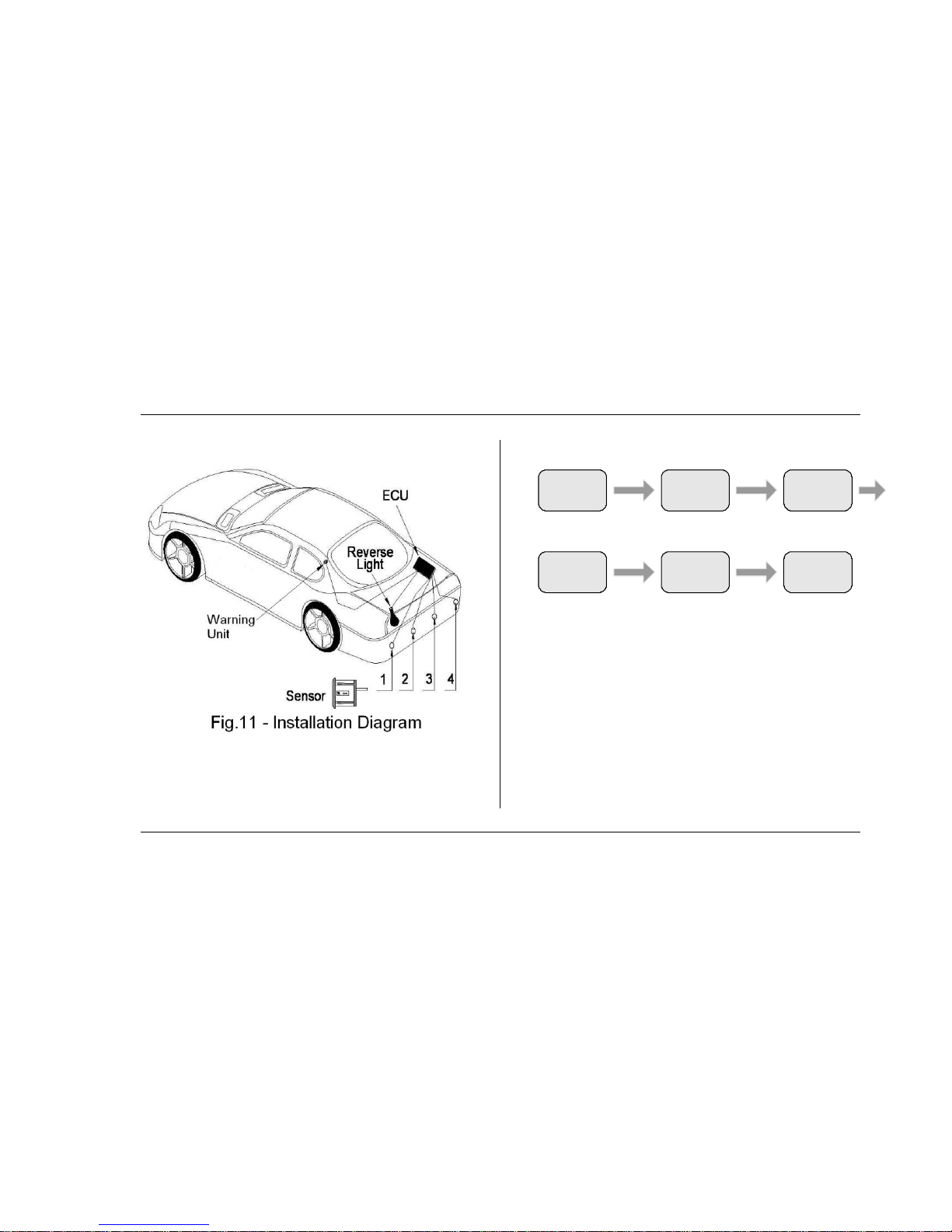
Fig.11 gives a general layout showing where to install the
components of the reverse parking system.
Installation Procedure
General layout
Determine where to install the ECU and warning unit
according t o the layout of your vehic le. Make sure the power
cable of the ECU c an be easily connected.
Sensor installation
For details, refer to “Tips on Sensor Installation” on page 10.
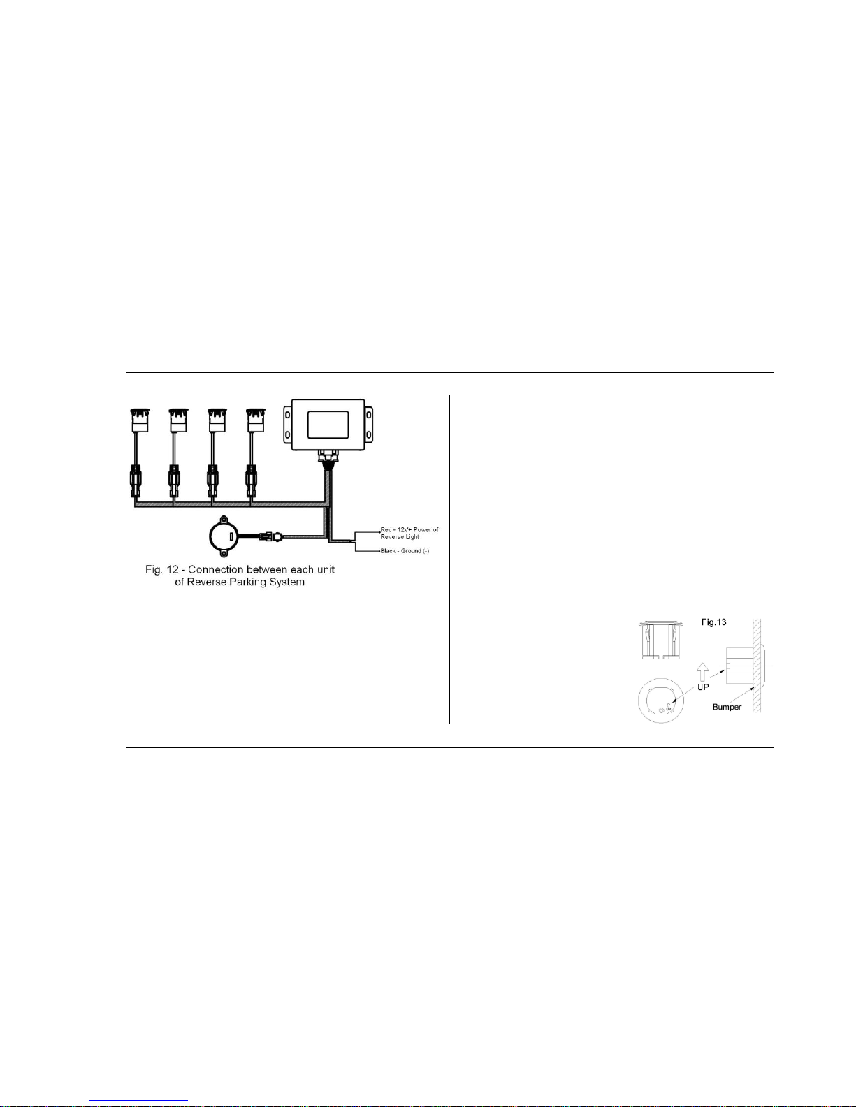
Co mponent Connection
See Fig.12 for t he connect ion between components of
reverse parking syst em.
General
Layout
Sensor
Installation
Component
Connection
Power
Connection
Parts
Inspection
Te st
Page 11
9
Parking Sensor System
Cont rol unit
The reverse parking system has 1 ECU that should be
installed near the back-up lamp in the trunk.
Warning unit
Install the warning un it using supplied adhesive st rip in a
location where the alarm can easily be heard by the driver of
the vehicle.
Powering up
For details, refer to “Powering up” on page 12.
Test
For details, refer to “Test the System” on page 13.
Note: Sensors and trunk harness connectors are serialized
and must be c onnected in position and order as shown in
Fig.2; otherwise the diagnostic function will reference the
wrong sensor.
Tips on Sensor Installation
Width of different vehic le models varies; it is very
impo rtant to c hoose the correct locations to install sensors.
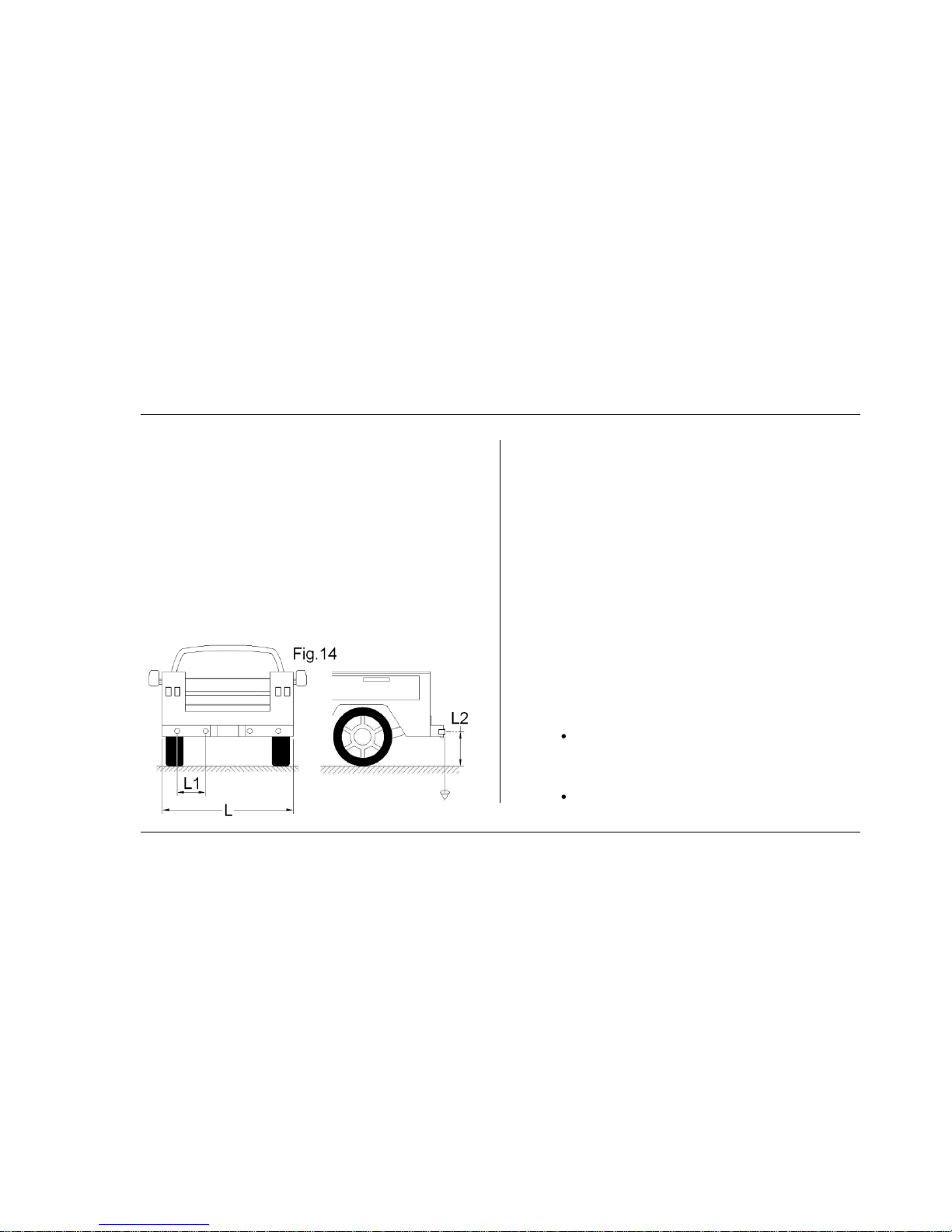
Sensors need to be
installed with the “Up” ma rk
facing up as shown in Fig.13.
Sensor must be fully
inserted and fit flush to
bumper fac e.
Page 12
10
Parking Sensor System
Area behind sensor must be open and not contact sensor
body (bumpe r, mounting brackets, foam…etc .).
The face of the sensor should be perpendicular to the
ground. If t he bumpe r surfac e is angled, use the supplied
angled bezels to compensate.
Note: To use angled bezels, first, carefully remove bezel
from sensor. Snap correct angled bezel on sensor with bezel
angle in proper orientation.
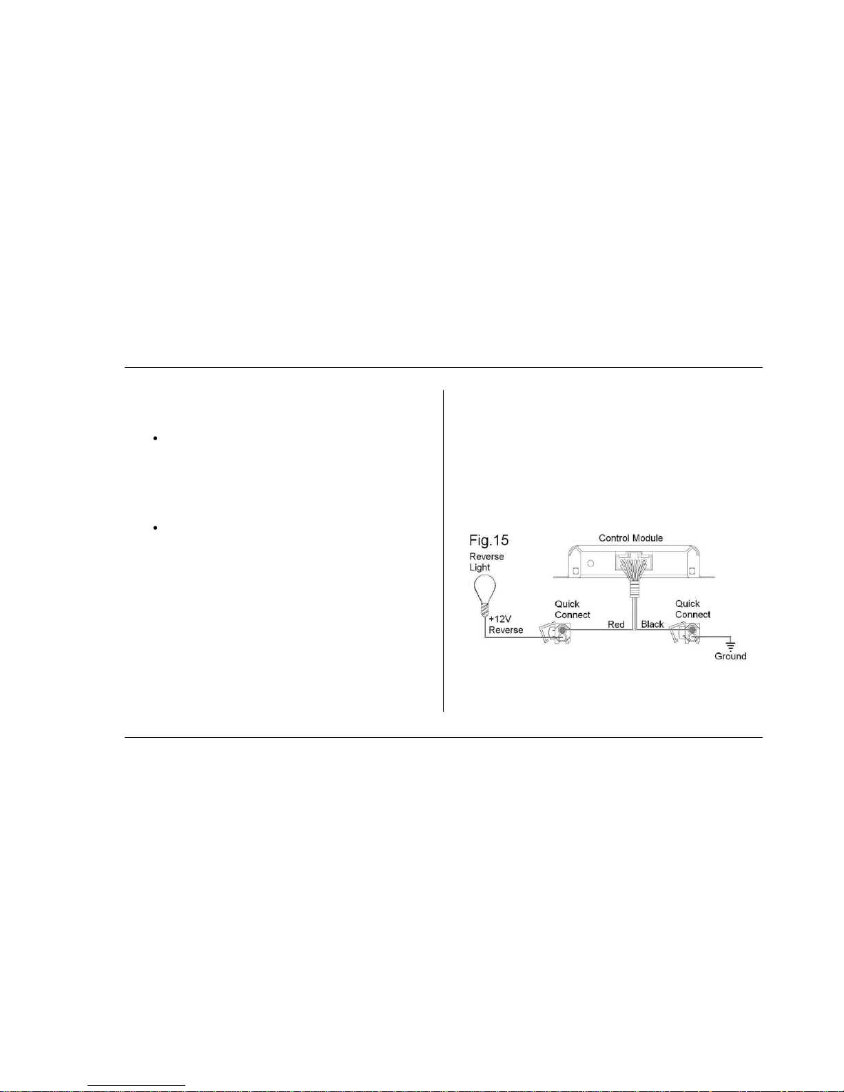
Horizontal and vertical positioning
See Fig.14, “L” is the width of vehic le. L1 is the horizontal
distance between sensors (L1=16”±2”). For a wider
detection angle, locate side sensors closer to t he lat eral
sides of the vehicle. L2 is the height of sensors
(L2=25”±5”).
Installation steps
· Mark the positions of each sensor on bumper with a
ma rker to ensure proper location.
· Drill holes using the included hole saw. (An M2/.079”
drill bit c an be used to drill pilot holes to aid in t his
process.)
· Remove t he burrs from the hole edge with a file.
· Insert the sensor c ables into the holes made in
bumper acc ording to serial number. Refer to Fig .2
IMPORTANT
Use correct hole saw. Sensors may not function
properly with holes that are too small or too large
in diameter.
Plastic bumpers require the 21.5mm ho le saw.
Page 13
11
Parking Sensor System
Plastic bumpers do not require t he rubber
sleeves included in kit.
Metal bumpers require the 24.5mm drill. Met al
bumpers require rubber sleeves installed before
installing sensors. (Note: The rubber sleeves
must be orient ed with "UP" not ation mounted
up).
Sensors can be re-painted to match the color of
your vehic le. Not e: The painting layer must be
symmet ric al and less than 0.1mm (.004 in.)
thick.
Under-Bumper Installation Steps
· Mark the positions of eac h sensor below the bumpe r
with a marker to ensure proper location.
· Mount brackets using the supplied hardware.
Note: Brackets must be mounted to ensure the center
axis of the sensor is parallel t o the center line of the
vehicle and perpendicular to the ground.
· Insert the rubber sleeves into the brackets.
· Insert the sensor c ables into the holes made in
bumper acc ording to serial number. Refer to Fig.2
Powering Up
Power connections of reverse parking syst em
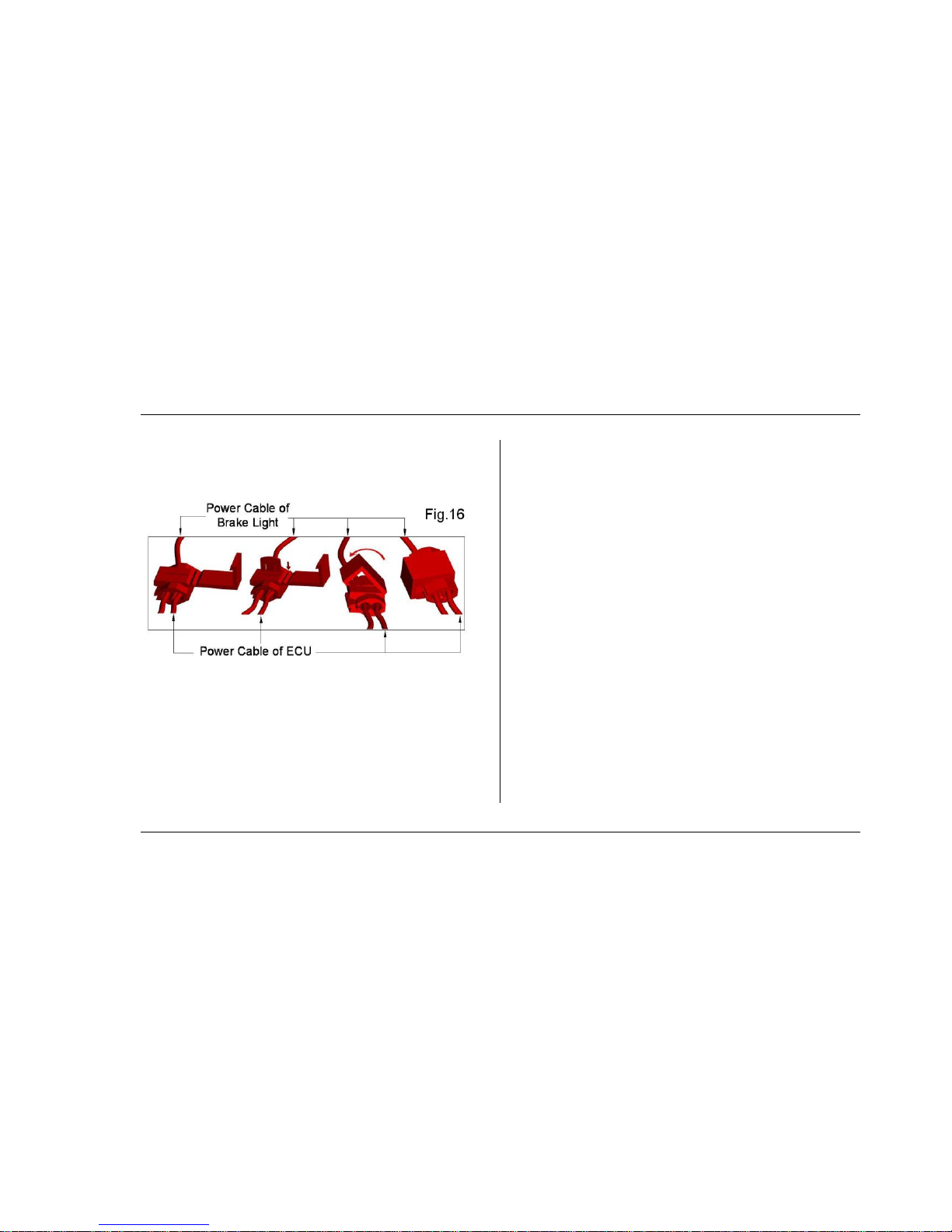
The control module gets power from the reverse light circuit
of the vehicle. Refer to Fig.15.
It is recommended t o solder all connections. If it is not
possible to solder the c onnections, use the supplied
Page 14
12
Parking Sensor System
electrical connectors.
· Press the metal part tightly to ensure cables are well
connected. See Fig.16.
Power connection steps:
Securely c onnect the red power cable of ECU t o t he +12V
wire of the reverse light;
Securely c onnect t he blac k ground cable of ECU to a
vehicle ground point.
Precautions
Vehic le engine must be off when installing the system.
The ECU must not be installed near any potential sources
of interference, e.g. exhaust pipe, other cables or groups of
cables.
Detection results may be affected if sensors are installed
in steel bumpers without rubber sleeves.
Ultrasonic and electromagnetic waves from ot her
sources near the system may affect detection results.
● TEST THE SYSTEM
Test Subjects
Audible warning Refer to Fig 3 and 5
Distance, direct ion and warning zones Refer to Fig 4 and 5
Page 15
13
Parking Sensor System
Turning on reverse parking syst em
Once reverse is engaged, system is auto matically act ivated;
when vehic le is shifted out of reverse gear, system stops
working.
Test Methods
Test tools
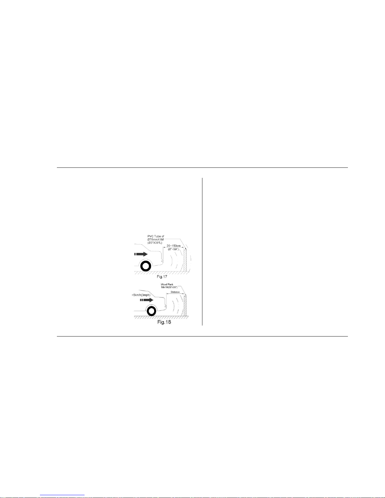
Conduct tests by using obstacles behind the vehicle.
Prepare a PVC t ube of
Ø75mmX1000mm(Ø3”X39”L)
for short distance test. Fig.17.
Prepare a wood plank of
500X500X10mm
(20”X20”X4”) for long
distance t est: >1.2M (47”) .
Fig.18.
Tests of rear detection
Turn the vehicle key t o “ON” position, don’t start the
vehicle engine.
Put vehicle in reverse gear, move the 2 obstac les forward
and bac kward 20~200cm(8”-79”) behind vehicle. System
should beep and/or visually show t he warning zones,
distance to and direction of the obstac les.
Check the sensors one by one. Refer to Fig.17 & 18.
● DISCLAIME R
The system is designed and intended as a warning aid for
parking only.
The supplier of this product accepts no responsibility for
any accident s and/or damage c aused during the use of this
system.
Detection results may be affected by environmental
conditions: i.e. rain, fog, snow, extreme t emperature. Due
to obstac le variability and road c ondions, warning levels
Page 16

14
Parking Sensor System
may vary or obstacles may be undetected.
Ult rasonic and electromagnet ic waves from other
sources near the system may affect detection results.
● TROUBLESHOOTING
F ault-Warning mode The following c hart shows what
the alarm sequence during a diagnostic-fault:
Diagram 4: A UDIBLE WARNING MODE
OF DIAGNOSTICS
Serial No. of
Defective Sensors
Audible Warning
1
Bi 2 Bi.Bi 3 Bi.Bi.Bi
4
Bi.Bi.Bi.Bi
Note: Multiple sensor faults may be
displayed in succession
Audible warning of diagnostics
If a sensor is found defect ive during diagnostics, the system
will tell you its serial number by beeping per Diagram 4. If all
sensors are defective, the system will beep a solid tone for
1.5 seconds.
Ex. 1: in case sensor No. 3 is abnorm al
When powered on, system be eps once for 0.5 se cond (signa l for
diagnostics), then rapidly beeps 3 times (signal of sensor No. 3 that is
abnormal). This a lert will continue eac h time the system is started until
the problem with sensor No. 3 is resolved.
Ex. 2: in case both sensors No. 2 and 4 are abnormal
When powered on, the system beeps once for 0.5 se cond, and then
rapidly beeps 2 times, you should power off the system and solve the
problem of sensor No.2. When you re-start the system, after the be ep
of 0.5 seco nd, the sy stem will beep rapidly4 times, indicating a problem
with sensor No. 4.
Page 17

15
Parking Sensor System
T he following chart provides you with solutions to a few simple problems
PROBLE M
REASON
SOLUTION
System doesn’t react when reverse is
engaged.
1.System is not powered up or wrong connection of
power cable.
2.Invalid connection between Warning Unit and ECU.
1.C heck the power and ground connections.
2. C heck the connection between Warning Unit and
ECU.
Afteractivation, system continuously
beeps for 3 seconds.
1. Invalid connection between sensors and ECU.
2. All sensors are defectiv e.
1. C heck the connection between sensors and EC U.
2. Replace the defective sensors.
The Warning Unit distance remains
the same while distance to obstacle
varies.
1. Incorrec t installation direction of sensors.
2. Incorrec t installation angle of sensors.
1. Follow the “UP” mark and re -install sensors.
2. Adjust the position of dete cting angle to avoid
downward detection.
In case no obstacle is found in the
detection range, Warning Unit
continuously beeps.
1.Sensor(s) is loose.
2. System is detecting vehicle itse lf or its spare parts,
for example the spare tire.
1. Ensure sensor is fixed tightly in bumper.
2. Adjust the position of sensors and the detection
angle.
Page 18

36,000 MILE/36 MONTH LIMITED WARRANTY
Rostra Pre cision Controls, Inc. (the Company) warrants to the original retail purchaser
of th is Produ ct that should this p roduct or any part th ereof, under normal use and
conditions, be proven d efective material or workmanship within 36 months of the
original purchase, such defect (s) will be repaired or replaced ( at the Company’s option)
without charge for the parts. To obtain repair or replacement within the terms of this Warranty, the product is to be
delivered with proof of warranty coverage (e.g. dated b ill of sale), specification of
defect(s), transportation prepaid, to the installing dealer and/or retailer. This Warranty does not c over costs incurred for removal or reinstallation of the
product, or damage to vehicle electrical systems. This Warranty does not apply to any product or part thereof which in the opinion of the
Company h as been damaged throug h alteration, improper installation, mishandling,
misuse, neglect, or accident. This Warranty is in lieu of al l other express warranties or liabilities. ANY IMPLIED
WARRANTIE S, INCLUDING ANY IMPLIED WARRANTY OF MERCHAN TABILITY, SHALL BE
LIMITED TO THE DURATION OF THIS WRITTEN WARRANTY. ANY ACTION FOR BREACH
OF ANY WARRANTY HEREUNDER INCLUDING ANY IMPLIED WARRANTY OF
MERCHANTABILITY MUST BE BROUGHT WITHIN A PERIOD OF 42 MONTHS FROM DATE
OF O RIGINAL PURCHASE. IN NO CASE SHALL THE COMPANY BE LIABLE F OR ANY
CONSEQUENTIAL OR INCIDENTAL DAMAGES F OR BREACH OF THIS OR ANY OTHER
WARRANTY, EXPRESS OR IM PLIED, WHATSOEVER. No person or representative is
authorized to assume for the Company any liability other than expressed herein in
connection with the sale of this product. THE EXTENT OF THE COMPANY ’S LIABILIT Y UNDER THIS WARRANTY IS L IMITED TO
THE REPAIR OR REPLACEMENT PROVIDED ABOVE AND, IN NO EVENT, SHALL THE
COMPANY’S LIABILITY EXCEED THE PURCHASE PRICE PAID BY THE PURCHASER FOR
THE PRODUCT. Some states do not allow limitations on how long an implied wa rranty lasts or the
exclusion or limitation of incidental or consequential damage so the above limitations
or exclusions may not apply to you. This Warranty gives you specific legal rights and
you may also have other righ ts which vary from state to state.
OWNER’S WARRANTY RECORD
To be completed by installer and retained by customer
Customer’s Name Part #
Dealer Name
Dealer Address
City State Zip
Phone# Fax #
Email
Date Purchased Mileage Date Installed
Make Model Year
Vin#
Customer Complaint
Descrip tion of Defect/Repair
Notice to Installer: Contact your distributor for technical assistance or return
authorization. THIS CARD MUST BE COMPLETE AND ACCOMPANY THE
RETURNED PRODUCT. Any alteration to product, damage caused by installation or
use with any product not manu factured or recom mended by Rostra Precision Controls,
Inc. voids th e warranty & parts will be returned.
 Loading...