

Page 1
ULTRIX-FM-NS-2RU Install Guide
This document is intended to be used for module replacements only.
CAUTION: Before proceeding, refer to the “Important Regulatory and Safety Notices to Service Personnel” document that was included with your router. It is also recommended to refer to the Ultrix
Installation Guide which is available for download from our website.
Removing the Cooling Fan Module from the ULTRIX-FR2 Chassis
Caution — For reliable performance, the Ultrix router should not run without fans for more than 5
minutes.
The Cooling Fan Module is critical to the operation of the Ultrix router. Should a fan fail within the module, you will
need to replace the entire module with a new one (ULTRIX-FM-NS-2RU). You will also need to transfer the Micro
SD card from the failed Cooling Fan Module to the new module.
The Cooling Fan Module is accessed via the front of the router chassis and requires that you remove the door first. The
door is secured to the front of the router chassis with a rare earth magnet on each side.
The ULTRIX-FM-NS-2RU Cooling Fan Module is only installed in newer ULTRIX-FR2 routers.
The Cooling Fan Module replacement should be performed while the chassis is powered on.
To remove the door from the chassis
ESD Susceptibility — Static discharge can cause serious damage to sensitive semi-conductor
devices. Avoid handling circuit boards in high static environments such as carpeted areas and when
synthetic fiber clothing is worn. Always exercise proper grounding precautions when working on circuit
boards and related equipment.
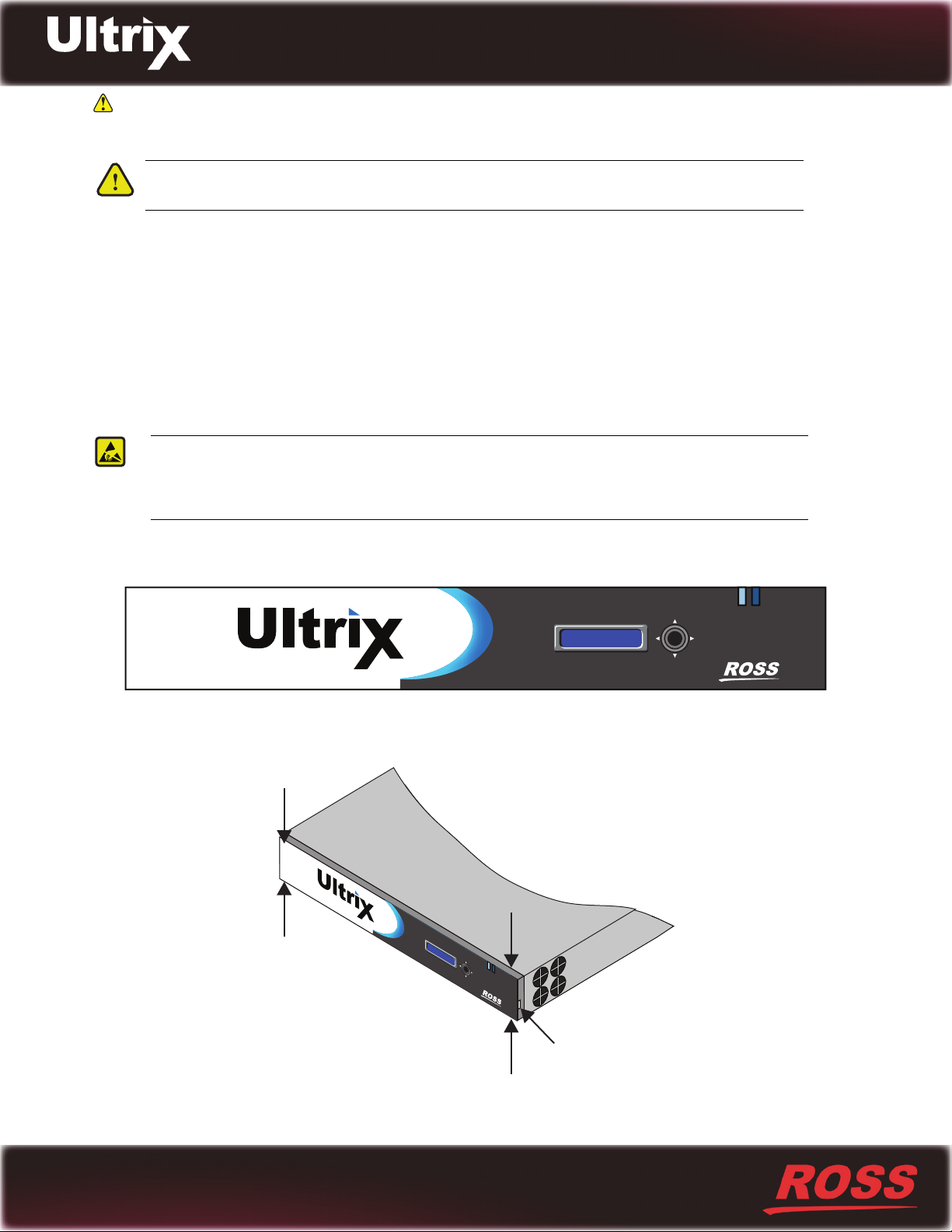
1. Verify that the router you are using is compatible with the ULTRIX-FM-NS-2RU by ensuring that the Ultrix logo
on the front door displays an “i” with a blue dot.
IP: ###.###.##.###
1234
2. With your left hand, grasp the top and bottom of the door at the left sides.
3. With your right hand, grasp the top and bottom of the door at the right side.
I
P: #
12
##
.#
#
3
I
#.
P: #
4
##
12
.###
##
.###.#
34
#
.###
Notch
Figure 1 Front Panel — Where to Grasp the Door
2101DR-486-01
© 2019 Ross Video Limited. Ross® and any related marks are trademarks or registered trademarks of Ross Video Ltd . All other trademarks are the property of their respective companies. PATENTS ISSUED and PENDING. All rights reserved. No part of this publication may be reproduced, stored in a retrieval system, or transmitted in
any form or by any means, mechanical, photocopying, recording or otherwise, without the prior written permission of Ross Video. While every precaution has been taken
in the preparation of this document, Ross Video assumes no responsibility for errors or omissions. Neither is any liability assumed for damages resulting from the use
of the information contained herein.
Page 2
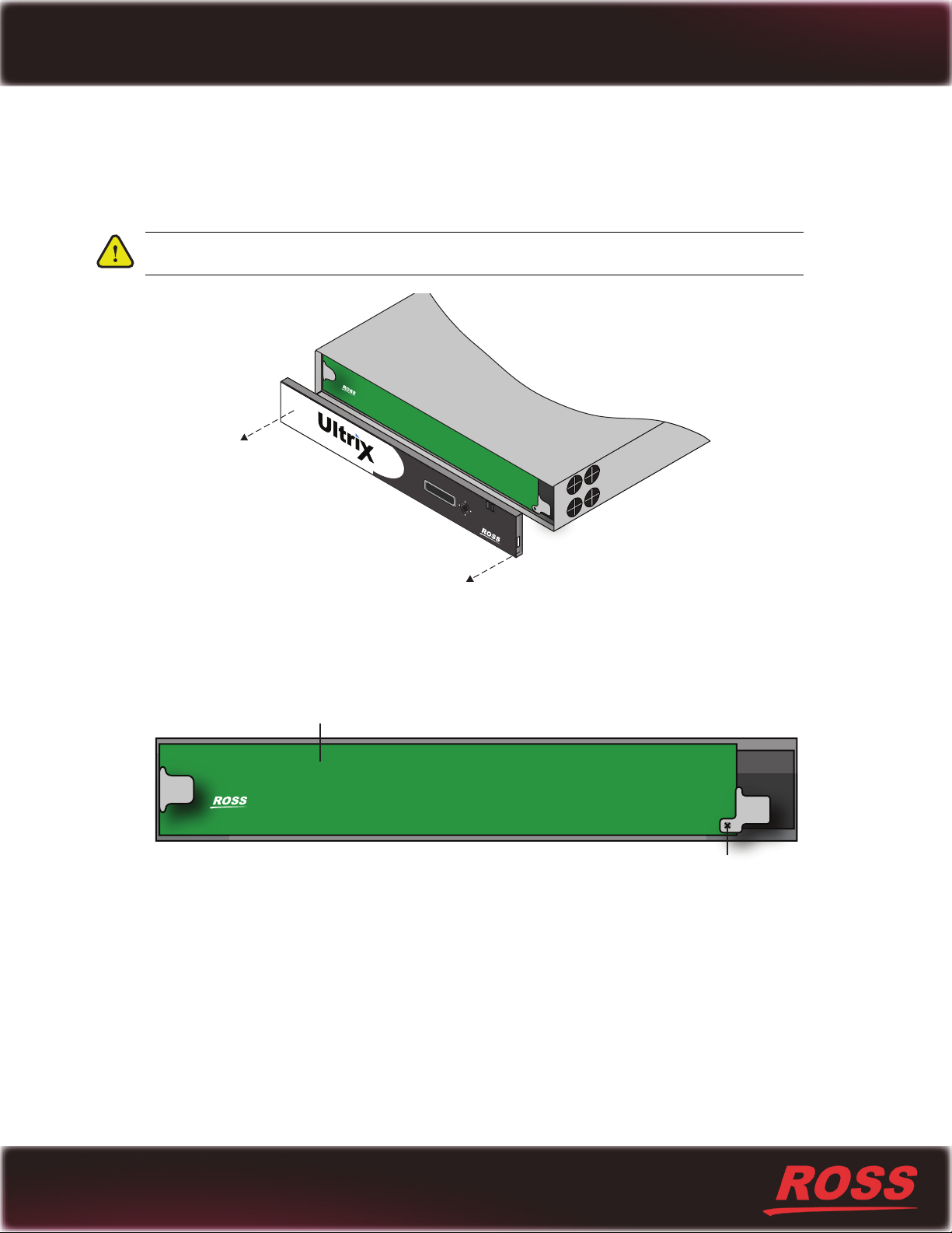
If you have trouble removing the door from the chassis, you can insert a flathead screwdriver into the notch on
IP: ###.#
##.##.###
IP: ###.
###.##.###
123
4
either side of the door for added leverage.
4. Pull the right side of the door towards you to disengage it approximately 1.0” from the chassis.
5. Pull the left side of the door towards you to fully disengage the door from the chassis.
Caution — Pull the door off without twisting or rotating it at too steep of an angle.
Figure 2 Front Panel — Removing the Door
To remove the Cooling Fan Module from the chassis
1. Remove the door as outlined in the section “To remove the door from the chassis”.
2. Use a #1 Phillips screwdriver to loosen the screw that affixes the Cooling Fan Module to the Main Board.
Main Board
Screw
Figure 3 Location of Screw for Cooling Fan Module
3. Gently pull the Cooling Fan Module towards you to unseat it from the backplane and to disengage the module
from the chassis.
Printed in Canada.
2
Page 3
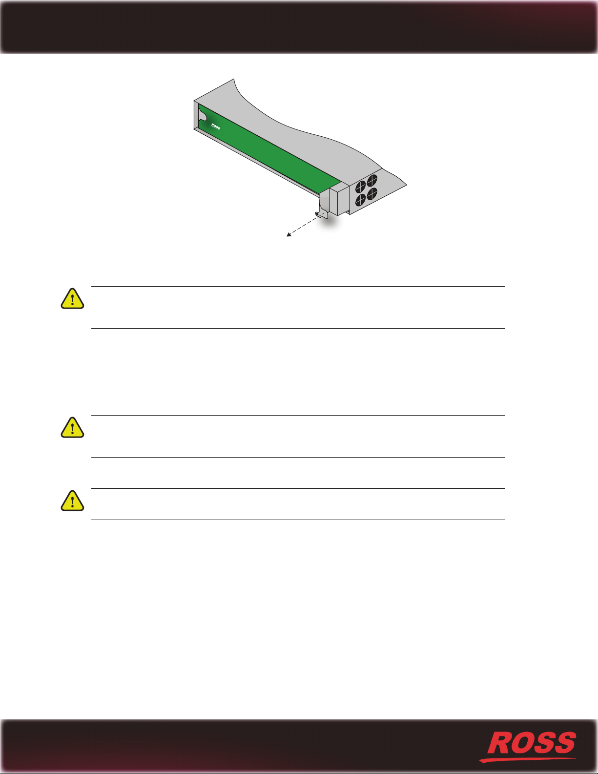
Figure 4 Removing the Cooling Fan Module from the Chassis
4. Pull the module free from the chassis and set it on a static-free surface.
Notice — Compare the failed Cooling Fan Module with the new module shipped to you for
replacement. Ensure that the new module includes the same number of fans as the failed module.
Contact Ross Video Technical Support if the modules do not match.
Installing the Micro SD Card into the New Cooling Fan Module
The Micro SD card provides system storage and a default software build. The Micro SD card slot is located inside the
Cooling Fan Module and between the first fan and the fan PCB in the module. You must remove the Micro SD card
from the failed Cooling Fan Module and install it in the new Cooling Fan Module.
Notice — You must use the Micro SD card from the failed Cooling Fan Module. Use of an alternate
Micro SD card will result in loss of vital system information. Swapping out the Micro SD card with a
different Micro SD card returns the router to its factory default settings.
To eject the Micro SD card from the failed Cooling Fan Module
Notice — Perform this procedure only if instructed by Ross Video Technical Support. Customer
supplied Micro SD cards may prevent and/or corrupt normal operation.
Printed in Canada.
3
1. Remove the Cooling Fan Module as outlined in the section “To remove the Cooling Fan Module from the
chassis”.
2. Locate the Micro SD card slot inside the failed Cooling Fan Module. Refer to Figure 5.
Page 4
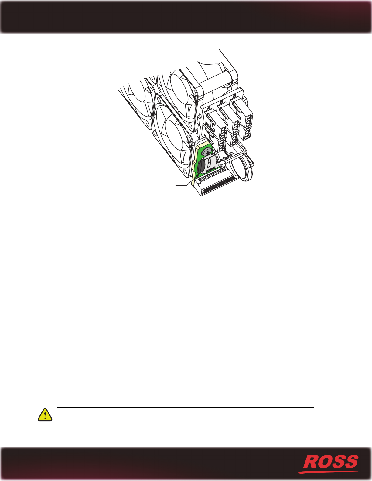
Figure 5 Location of Micro SD Card Slot — Between the Fan and the Fan Board
MicroSD Card
3. Gently press in on the Micro SD card so that it pops out from the slot.
4. Make a note of the orientation of the card in its slot. This will help with installing the Micro SD card into the new
Cooling Fan Module.
5. Gently pull the Micro SD card out.
To install the Micro SD card into the new Cooling Fan Module
1. Locate the Micro SD card slot inside the new Cooling Fan Module. Refer to Figure 5.
2. Orient the Micro SD card so that the printed side faces the fan and the print is upside down. Refer to Figure 6.
3. Carefully insert the Micro SD card into the slot.
The Micro SD card makes a faint clicking sound when it is fully inserted.
Installing a New Cooling Fan Module in the 2RU Chassis
Once you have installed the Micro SD card into the new Cooling Fan Module, you can install the new module into the
Ultrix chassis and replace the door on the front panel.
To install a new Cooling Fan Module into the chassis
1. Align the new Cooling Fan Module in the slot inside the chassis.
2. Gently push the Cooling Fan Module into the slot until the module is fully seated. You will feel the back
connector of the module engaged with its connector inside the chassis.
Printed in Canada.
4
3. Use the screw from step 2 in the procedure “To remove the Cooling Fan Module from the chassis” to affix the
Cooling Fan Module to the frame.
Caution — The Cooling Fan Module includes a connector that must be fully seated. Reinstalling the
Cooling Fan Module retention screw is required to ensure proper contact.
Page 5
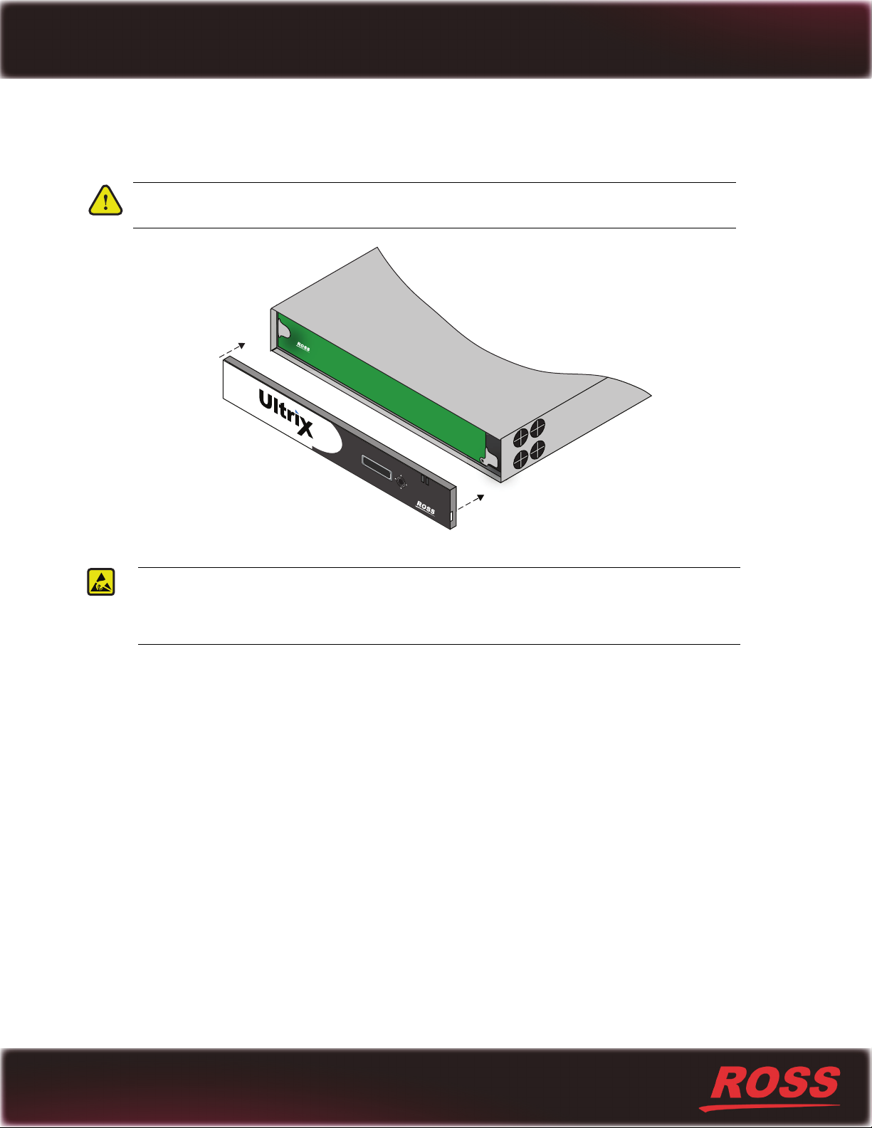
To re-install the door to the chassis
1. Align the door to the front of the router, ensuring that the door is oriented upright, the corner with the Ultrix logo
is in your left hand, and the corner with the Ross logo is in your right hand. Refer to Figure 6.
Caution — Re-installing the door incorrectly or misaligned can damage the door or internal
components.
IP: ##
#
.
###.
I
P: ###.#
##.###
1
2
##.
3
4
##.###
Figure 6 Front Panel — Aligning the Door to the Chassis
ESD Susceptibility — Static discharge can cause serious damage to sensitive semi-conductor
devices. Avoid handling circuit boards in high static environments such as carpeted areas and when
synthetic fiber clothing is worn. Always exercise proper grounding precautions when working on circuit
boards and related equipment.
2. Align the left-side of the door against the chassis.
3. Align the right-side of the door, gently rotating the door into position.
4. Verify that the door is fully seated in place with the magnets securing it to the chassis.
Printed in Canada.
5
 Loading...