

Page 1
Quick Start Guide for PTZ-12G and PTZ-NDI Cameras
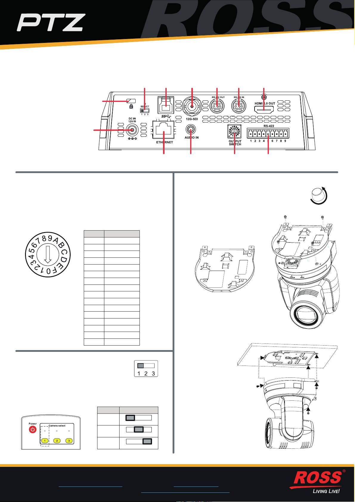
1) Camera Connection Panel
Kensington
Lock Port
DC 12V
Input
IR
Select
USB 3.0 12G SDI
Output
RS-232
Output
RS-232
Input
HDMI 2.0
Output
Ethernet PoE++ (all models)
NDI|HX (PTZ-NDI model)
2) Video Output Switch
Rotate the Video Output Switch to select the video
output format. The arrow points to the current format.
The factory-set default position is 0 : 2160p/59.94.
Tip: Alternatively, you can set the video format using
the web interface. For more information, see Technical
Manual for PTZ-12G and PTZ-NDI (5000DR-353-01).
Output ModeSetting
2160p/59.940
2160p/501
2
9
A
B
C
D
E
F
2160p/29.97
2160p/253
1080p/59.944
1080p/505
1080p/29.976
1080p/257
720p/59.948
720p/50
720p/29.97
720p/25
1080i/59.94
1080i/50
Reserved
Reserved
Audio
Input
Switch
RS-422Output
4) Mounting the Camera
a) Remove the foot pads (4 pcs) from the
bottom of the camera by rotating them
counter-clockwise.
Store the foot pads for future use.
b) Using four silver M3 screws
(included), fasten Metal Plate A
to the base of the camera.
Metal Plate A
c) Attach Metal Plate B to the
ceiling, using suitable fasteners.
Note: Allow adequate space for
connecting cables to the back
of the camera.
d) Align the two Metal Plates and slide them together.
3) IR Select Switch
The IR Select Switch assigns a number
(1, 2, or 3) to the camera.
When you later use a remote control, you can select
which camera (1, 2, or 3) you want to control.
Remote Control
© 2021 Ross Video Limited. All rights reserved.
Need Help? Our friendly, knowledgeable Ross Video Technical Support staff are always available!
1
• Telephone +1 613-652-4886; or toll-free 1-844-652-0645 (North America), +800 1005 0100 (International)
• E-mail [email protected], or visit our website at www.rossvideo.com
• Contact the ROSS VIDEO | HELP CENTER at https://support.rossvideo.com/hc/en-us
Switch PositionNumber
1
2
3
1 2 3
1 2 3
1 2 3
Black M3 Screw
e) Fasten the Metal Plates
together using two silver
M3 screws (back) and one
black M3 screw (front).
Screws are included.
5000DR-351-01
Page 2
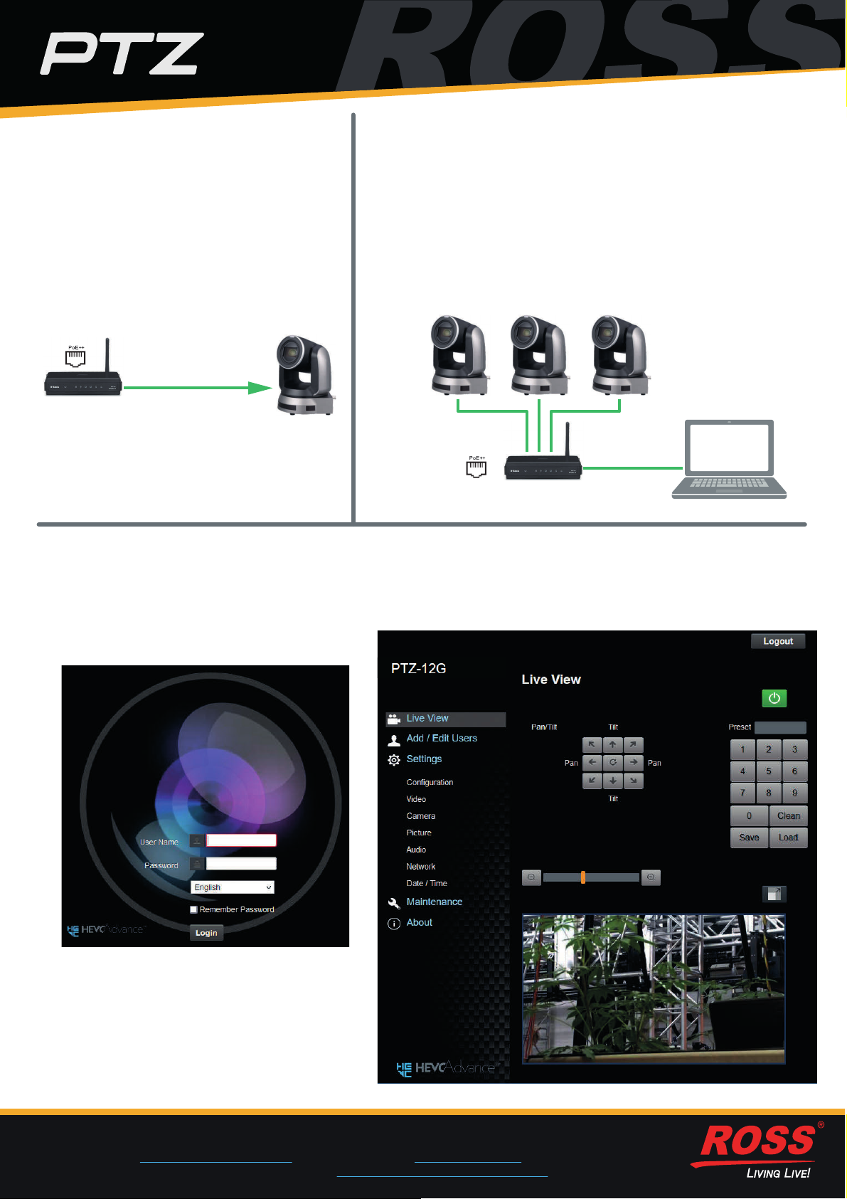
5) Providing Power to the Camera
To power the camera, do one of the
following:
• Connect the provided 12 VDC power
supply unit.
• Using CAT6 network cable, connect the
Ethernet port of the camera to a
network router or hub that supports
Power over Ethernet (PoE).
The camera requires PoE++
(IEEE802.3bt).
CAT6 Network Cable
Router
(PoE++ capable)
Camera
6) Camera Networking
a) Connect all cameras and control systems to the same network.
b) Use the remote control to either turn on DHCP or to assign each
camera a unique IP address:
• To turn on DHCP, select Menu > Ethernet > DHCP > On.
Note: The network must be configured for DHCP.
• To assign an IP address, select Menu > Ethernet > IP Address,
and then specify the IP address.
Tip: The default IP Address is 192.168.100.100.
Camera CameraCamera
Router
(PoE++ capable)
7) Access the Camera Web Interface
The web interface enables you to configure camera settings and view camera video, using a web browser.
a) On a computer connected to the same network as the camera, launch a web browser.
b) In the address bar of the web browser,
type the IP address of the camera, and
then press Enter.
The login page of web interface appears:
Camera Web Interface
Control
Computer
Tip: You can use the remote control to
view the IP address. Press Menu >
Ethernet > IP Address.
c) Provide the User Name and Password,
and then click the Login button.
The login page of web interface appears.
Tip: The default User Name is admin.
The default Password is 9999.
Need Help? Our friendly, knowledgeable Ross Video Technical Support staff are always available!
2
• Telephone +1 613-652-4886; or toll-free 1-844-652-0645 (North America), +800 1005 0100 (International)
• E-mail [email protected], or visit our website at www.rossvideo.com
• Contact the ROSS VIDEO | HELP CENTER at https://support.rossvideo.com/hc/en-us
 Loading...