


User Instructions
Release n. 03/eng- June 11th, 2016


Table of contents
Warnings and handbook keeping pag. 01
Safety pag. 02
Techincal data pag. 05
Labels and plates pag. 07
How is made pag. 08
Lifting and carrying pag, 08
Indoor oven installation pag. 09
First start pag. 11
Lightings and baking pag. 12
Cleaning pag. 13
Scheme and list of the components ( forced convection ovens
exept “Garden”)
Scheme and list of the components of “Garden” model pag. 16
Scheme and list of the components (static ovens) pag. 18
Electrical diagram pag. 20
Bulb replacement pag. 20
troubleshooting pag. 21
Warranty pag. 23
Declaration of CE conformity pag. 25
pag. 14


NOTICE
This manual provides information for the transport, installation, correct use and
maintenance of the Rossofuoco’s ovens; it is aimed at people involved in the installation,
use and maintenance of the equipment.
Before carrying out any operation, read carefully these instructions.
In case of doubts about the correct interpretation of the instructions, contact the
manufacturer or the reseller to obtain the clarications that you need.
it is forbidden to carry out any operation without having read and understood the
contents of this manual.
non-compliance, even partial, of the recommendations contained in this handbook
may lead to dangers for the user, the irregular operation of the oven and possible
damage to the equipment.
The manufacturer is not liable for damages or injury resulting from failure to observe
this prohibition.
HANDBOOK KEEPING
This manual is an integral part of the product.
It must always accompany the oven even in case of trasfert to other people.
This document should always be available for sta enabled to install, for the use and to
perform the maintenance of the oven.
It must be kept in the immediate vicinity thereof.
The document must be preserved in good condition and easily readable during the all
lifetime of the oven.
Consequently:
• keep this manual in a place protected from heat and moisture, away from liquids.
• use the document without damaging it.
• do not tear the pages and don’t modify the contents of this handbook.
In the event that this booklet has damages that may impair its legibility, or is lost, you
will immediately request a replacement copy from the manufacturer or from the reseller.
01 of 26

SAFETY AND E CONTRAINDICATIONS
Read carefully the entire manual.
01) The oven is designed exclusively for cooking food and should not be used for any other
purpose.
02) The oven is intended for domestic use only. The operator before using the equipment must
read and know all the safety precautions outlined in this document.
03) All local regulations, including those that refer to national and European laws must be
respected when installing or using the unit.
04) The oven must be placed on a oor or platform leveled, with load-bearing capacity appropriated
to substain the weight of the oven declared by the manufacturer (for built-in ovens also see
pag.08).
If you install the oven on the cart supplied by the manufacturer use a proper equipment for
lifting and handling the equipment (also see pag. 08); the oor or the platform must be
appropriated to sustain the weight of the equipment in the support points of the cart.
If the characteristics of the oor or of the platform where you intend to place the oven are not
responding to the needs use approriated load distribution plates.
05) When you install the oven remove all the protective lms, the internal and the external
packagings.
06) The outdoor oven must be placed in a suitable position so that the smoke does not create
any damage or trouble.
07) The oven must be installed to provide access to clean the ue.
08) The connection to the mains must be carried out in accordance with the safety standards in
force in the country of use.
09) The socket which connect the oven must be:
• Complies with the type of plug installed in the same.
• Sized to comply with the nameplate data for power equipment.
• Connected to an ecient earthing system.
• Connected to a power supply system with a protecting device against overload and discharge
currents (breaker / dierential or similar devices) in accordance with the rules laid down by the
European and national laws.
10) The power cord must not:
• come in contact with any type of liquid.
• come in contact with hot surfaces or parts of the equipment.
• be crushed and / or come in contact with sharp surfaces.
• be used to move the equipment.
• be used if damaged.
• be handled with damp or wet hands.
• be wrapped in coil when the oven is working.
• be manipulated.
11) Place any furniture at a distance greater than 15 cm from the oven walls, and 50 cm from the
radiation area of the front doors.
12) Use the oven only when equipped with oven mitts able to provide adequate protection
against heat.
13) Do not touch the oven during normal operation without these protections.
14) WARNING: Accessible parts may become hot during use. Children should be kept away.
15) The oven should be fuelled only with dry virgin wood of small size; it is forbidden to burn any
other material as (for example) pieces of chipboard, “medium density”, pieces of painted wood
panel pieces that may contain resins, foils ant or other media nishing of wood.
17) The use of types of wood dierent from virgin wood can generate toxic combustion gas
and cause damage to the structure of the oven.
The combustion of materials dierent from virgin wood is also prohibited by law.
02 of 26

18) The oven must be steadily controlled by the user during its normal operation.
19) The combustion chamber must always remain closed during operation of the oven, except
during the charging of the wood.
20)The oven must not exceed a temperature of 400 °C (752 F) , beyond this temperature the yield
is not optimal and the equipment can be damaged.
To avoid exceeding this threshold, do not introduce wood in quantities greater than 5 kg at
power up.
21) Never introduce paper, plastic or siliconic materials in order to avoid possible generations of
ames.
22) If you see smoke, turn o the power or unplug the appliance and keep the door closed in order
to extinguish any ames.
23) Follow the detailed instructions for cleaning door seals, cavities and adjacent parts.
24) Clean the oven regularly and remove any residual food. Neglecting to clean the oven could
cause a deterioration of the surface that could adversely aect the life of the device and lead
to dangerous situations.
In addition, where possible, periodically, before switching the oven clean the smoke duct and
the ue, in particular to check for obstructions, especially after a long period of inactivity of the
equipment.
Before cleaning the oven be sure to disconnect the plug from the socket.
Clean the equipment thoroughly following the procedures indicated in this manual.
25) After each use the temperature of the oven remains at high values for a long time.
Make sure that the temperature of the inner and outer walls has reached room temperature
before acting on the oven without the necessary protections.
26) It is recommended to discharge the ashes each time, before the use of the equipment.
When you do it check that there are not burning or hot coals, to avoid burns and / or re and,
however, put the ashes in a steel bin or made with similar material.
27) Any repair, replacement or maintenance must be performed by qualied technician
authorized by the manufacturer.
28) Please contact your dealer or the manufacturer directly for the resolution of any problem.
29) Any type of work on the domestic system that may be necessary to install and use the oven,
should be performed by qualied technician and in accordance with the laws in force in the
country where you live and where you intend to use the equipment.
30) WARNING: IN you need to replace the lamp, to avoid the possibility of electric shock, make
sure that the appliance is switched o and disconnected from the power supply before doing it.
Follow the replacement instructions mentioned in the section “Electrical System” of this manual.
31) In case of re, use carbon dioxide (CO2) extinguishers ; do not use water or powder extinguishers.
32) It is also strictly prohibited:
• Install the unit in a manner dierent from how in this manual.
• Install the equipment in presence of sources that can cause possible combustion (ames,
cigarettes, sparks, etc.).
• Install the unit in areas where there is the possibility of water jets.
• Install and use the equipment close to combustible materials, ammable and / or explosive, or
in places with hazardous atmospheres of re.
• Smoke while using the device, or get closer with devices that can generate combustion, such as
cigarettes or lighters lit, any kind of ames, scintillators.
33) Do not modify the equipment or perform technical operations that are not authorized by the
manufacturer. Each technical maintenance or repairs should always be carried out at specialized
centers authorized by the manufacturer.
34) Do not use any accessories other than those supplied with the oven.
03 of 26

35) Do not use the device in dierent ways and / or for purposes other than those specied in this
manual.; in particular, the appliance should not be used as an incinerator.
36) Don’t use fuels other than those recommended, including liquids.
37) Do not use the unit in physical and mental condition impaired, or under the inuence of
alcohol, narcotics or psychotropic drugs.
38) Do not cover, damage or remove the license and/or techincal plates appliated on the oven
and on it’s accessories.
WARNING
In case of improper use any form of guarantee is void and the manufacturer declines any
responsibility for damages to persons and / or things.
Improper use means:
• any use other than that specied in this manual.
• any use made with ways or techniques other than those permitted in this manual.
• any work on the apparatus in contrast with the instructions provided in this manual.
• any use after tampering of components and / or after alteration of the safety devices.
• any use after repairs performed with unauthorized components.
04 of 26

TECHNICAL DATA AND LABELING
technical data
Table 1 – technical data of the equipment
General Descrizione
Manufacturer ROSSOFUOCO s.r.l. unipersonale
manufacturer’s brand Rossofuoco
Model see rating plate on the oven
Serial number see rating plate on the oven
ELECTRICAL SPECIFICATIONS
Rated supply voltage 230 V
Rated supply frequency 50 Hz
Rated output power 60 W
Secondary supply voltage of the transformer 12 V
Insulation class II
IP Degree of protection IP X4
Width x Length x Height; Weight(*); *
(height of the outdoor models without chimney; height of the indoor models expet smoke pype(15mm))
Outdoor oven ECO 50 with trolley
Outdoor ovens type 65
Outdoor ovens type 80
Outdoor oven SEDICINONI
Outdoor ovens type 100
DIMENSIONS AND WEIGHT OF THE OVENS
with trolley
with trolley
with trolley
with trolley
( for outdoor models is intended with trolley)
Via Cavaleri di Vittorio Veneto, 21
61045 PERGOLA (PU) - ITALY
Tel. +39 0721/735926
fax +39 0721/737107
840x890x1745 mm; 154 kg
1000x1050x1770 mm; 234 kg
1060x1180x1770 mm; 271 kg
1250x1070x1820 mm; 277 kg
1060x1380x1770 mm; 325 kg
Indoor oven ECO 50
Indoor ovens type 65
Indoor ovens type 80
Indoor oven SEDICINONI
Indoor ovens type100
610x690x850 mm; 115 Kg
750X810X970 mm; 178 Kg
800x970x970 mm; 205 Kg
1000X820X1000 mm; 205 Kg
800X1170X970 mm; 253 Kg
05 of 26

CLIMATE CONDITIONS OF USE
Temperature: 5 – 40 °C
Relative humidity 20 – 90 %
FEATURES OF THE LAMP
Type Halogen
Voltage 12 V ac
Power 20 W
THERMAL FEATURES
Maximum load of rewood 4 Kg max
Caloric Value low. Ki 3500 Kcal/Kg
Usefule Thermal Energy (Q) 8500 Kcal/load
Maximum temperature of the oven (Tf) 400 °C
Maximum temperature of the combustion chamber
(Tcc)
Mass ow of combustion gases 7,5 g/s
Flue gas temperature after the stub pipe 270 °C
Minimum supply pressure to the rated thermal
output
850 °C
0,10 mBar
06 of 26
Included Accessories with the oven
Oven mitts - User and installation handbook

Labeling
Fig. 1 - data label installed on the oven
ROSSOFUOCO srl unipersonale
Via Cavalieri di Vittorio Veneto, 21 - 61045 PERGOLA (PU)
ITALY
Model:
Voltage:
Read and follow the operating instructions
Fig. 2 - Security labels installed on the oven
Frequency: Power:
Use only recommended fuels
WARNING: high temperatures
do not touch with hands
07 of 26

TECHNICAL DESCRIPTION OF THE OVEN
The oven consists essentially of a metal casing (or container), of an internal chamber
called cooking chamber and another separated chamber airtight called combustion
chamber that is connected directly to a particular ue for the output of the smoke. In
the lateral spaces between the side panels and the cooking chamber, has been applied
an additional layer of thermal insulation (rock wool) to better protect the outer walls of
the oven by the heat and improve the maintenance of right temperature in the cooking
chamber, that so will last longer constant.
The cooking chamber is all made with hi quality polished stainless steel, specically
suitable for food; the interior thereof, is assembled “cold”, with screws and slots capable
of absorbing without deformations the thermal expansion due to heat.
All materials that remain in contact with atmospheric agents are treated with additional
protection against corrosion that prolongs the durability.
The exclusive system for conveying fumes has also allowed us to create a totally square
cooking chamber, without the usual vault;
so our oven has more space to contain and cook everything well, on any hob, ensuring
on each level the same volume of air and an almost identical amount of heat.
In the cooking chamber it’s possible to accommodate in the same time three shelves
at dierent heights; in the lower part of the room is positioned a refractory plate which
also has the function of allowing a more uniform distribution of the internal heat.
On most of our ovens are installed two valves: one for adjusting the smoke outlet and
one to adjust the output of the steam from the cooking chamber.
The oven is equipped with a thermometer to check the temperature inside the cooking
chamber, a timer, interior lighting, ventilation, chrome grilles, trays, poker and pan
holder.
LIFTING AND CARRYING
For lifting and moving the oven use an appropriate equipment able to substain its
weight.
The oven can be lifted using the appropriate engagement (pos. 20) located inside the
outlet duct of the fumes.
Once unpacked, never lift the oven using systems forks; it ‘s absolutely forbidden to lift
the oven by hand.
The oven can be equipped, where not supplied as standard, with our cart (supplied
separately on request), with
extractable handles (position 3)
and with wheels (position 2) .
The cart is made for small
shifts of the oven in the area
where you are using it. Avoid
to move the oven on inclined
planes. Avoid to move the oven
when it is working.
08 of 26

HOW TO INSTALL THE BUILT-IN OVEN
For the installation of the built-in oven, in addition to what is indicated in other parts of
this manual, the following is recommended:
1. To place the oven prepare a compartment with two supporting walls with longitudinal
length equal to that of the oven and with a recommended height of about 60/70
centimeters, or use our specic metal support (optional); the oven should be installed
so that it can be moved easily for any maintenance if necessary;
2.Depending on the location (near or far from ammable materials) follow the minimum
requirements set out in the diagram on the next page;
3.Connect the smoke pipe of the oven to the chimney with a stainless steel tube
(130mm diameter);
4. Check that the ue is sized appropriately for the draft in compliance with the
regulations in force in the country where the oven is installed;
The section must be no less than 120x120mm (if square) or with a diameter of at least
150mm (if round);
5. In case of realization of a counterhood above the oven, in order to facilitate any
maintenance, it is essential to make it removable or equip it with an opening part (see
scheme 1 and 2 in the next page);
6. if it is not already present in the oven, apply a damper (this could be useful in
chimneys over 2m.); make sure that the chimney is free from obstructions. The damper
shall be of the type that does not totally block the smoke even in case of accumulation
of combustion residues. The damper must be easy to handle and with an opening in
the plate which, in a continuous area, occupies at least 20cm ² or 3% of the section of
the plate if this is larger;
7. Channelized output of the vapors, from the control valve to the outside, or in any case
in an area not watertight;
8. The AC adaptor supplied with the oven must remain accessible for any check
and maintenance, so install it in a xed position outside the masonry wall of the
compartment that houses the oven;
9.Ensure that the ventilation engine on the rear of the oven has always enough space
for the ow of the air required to keep it cool;
10.Make sure that the room where you instal installation the oven has a proper air
exchange (refer to the relevant laws in force in your country).
NB: an installation that does not comply with even one of the above conditions cause
the void of the warranty and exempts the manufacturer from any liability for any
consequence.
09 of 26
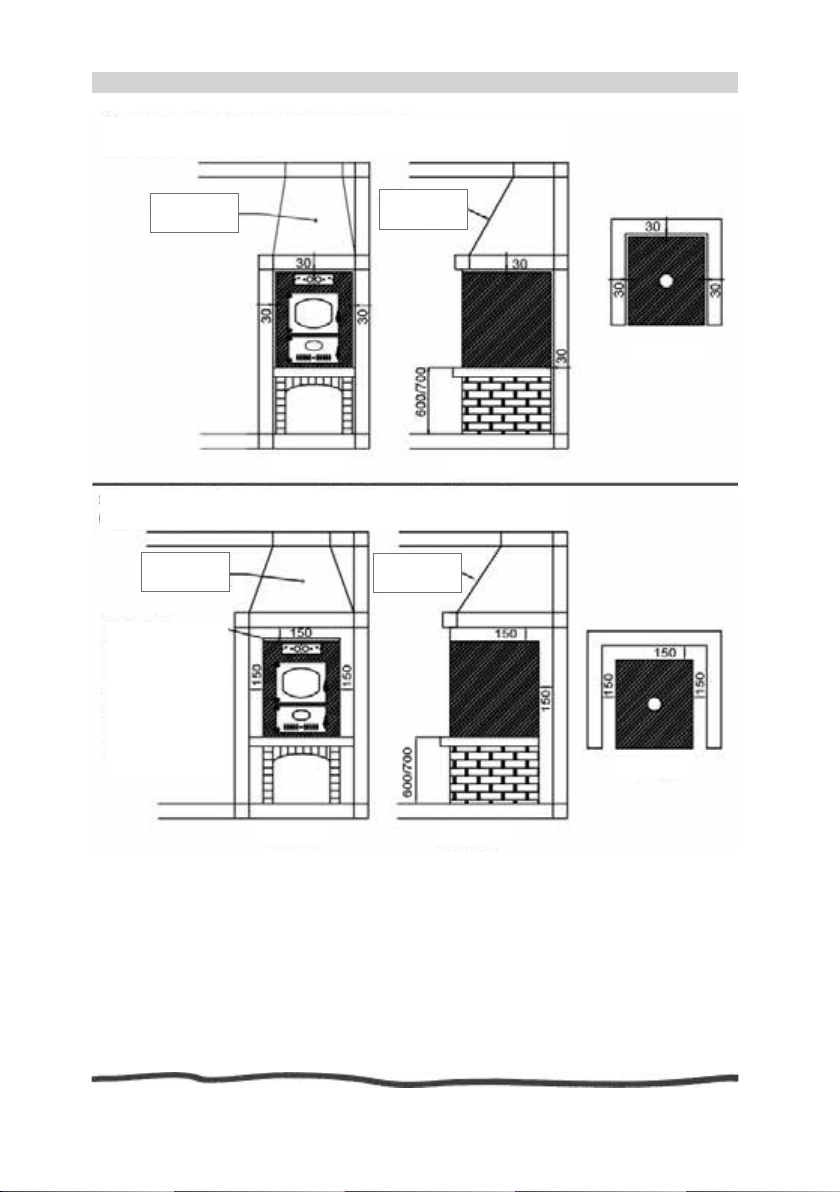
Fig. 3 - Scheme for mounting the built-in oven
Diagram 1: standard installation in masonry
(dimensions in millimeters)
Removable
counterhood
Front view
Diagram 2: installation near inammable materials
(dimensions in millimeters)
Removable
counterhood
In the case of coating with removable
ange, for a proper
circulation of air,
leave a slot of at
least 270 cm ².
Removable
counterhood
Removable
counterhood
Plant
Side view
Plant
Front view
Side view
An installation that does not comply with even one of the above conditions cause
the void of the warranty and exempts the manufacturer from any liability for any
consequence.
10 of 26
FIRST START OF THE OVEN
The rst lighting of a new oven must be done without cooking any of food.
Proceed as follows:
Load the combustion chamber (the lower door with louvers to adjust the air - page. 14
- Pos. 26 or page 16 - Pos. 14) with small pieces of dry virgin wood putting it above the
grid; for the rst lighting 2/3 kg of wood are enough.
Make sure that everything is set for the correct functioning; open the smoke valve
(where applicable) and then light the re using some very small pieces of wood or some
few little pieces of paper.
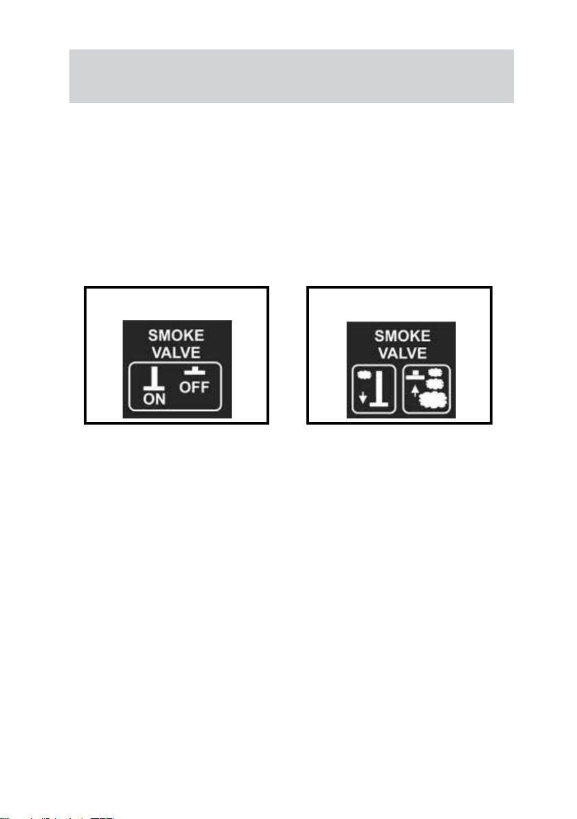
Warning: the action of the knob on the valve fumes was reversed on models produced from 1 January 2013 where,
to open the valve and increase the output of the fumes, the knob must be pushed towards the oven.
Position of the smoke valve knob for models
manufactured before January 1st. 2013
(Be careful to never use any type of liquid or gaseous fuel or explosive mixtures as well
as chemicals or petroleum-based, or alcohol or gasoline or anything not made for these
purposes.)
Position of the smoke valve knob for mo-
dels manufactured after January 1st. 2013
After starting the re close the door leaving fully open the slots for the airow so that
the wood burns well to turns into burning coals.
In this rst ignition phase heat the oven over 150 °C (302°F), but without reaching the
maximum temperature, and leave it on for an hour; this will eliminate the residual of
moisture from the rebricks.
Do not worry if you see whitish smoke and feel unpleasant smells; it is normal at the rst
heating of the new materials.
Please remember that the release of whitish smoke and unpleasant smells may
continue for 5/6 ignitions; this does not means a malfunction.
If the temperature inside the cooking chamber rises too, you can momentarily open
the door of the cooking chamber to let out a bit of hot air, or you can act on the slits on
the door of the combustion chamber to decrease the air ow on the coals in order to
reduce the combustion.
After this rst start the oven is ready for normal use.
11 of 26

LIGHTING THE OVEN AND COOKING FOODS
Repeat the lighting procedure as described on the previous page, but changing the
amount of wood to be inserted in relation to what you are going to cook (the scheme
on the next page will help you).
During the lighting phase open the valve that regulates the output of fumes and
adjustable slots on the door of the combustion chamber.
It is important to keep in mind that the oven should work with burning coals and not
with vivid ame inside the combustion chamber.
The amount of wood recommended is approximate and calculated to reach the right
operating temperature of the oven in the same time in wich the burning wood turns to
hot coals; hot coals instead of vivid ames will give to the cooking chamber the right
heat for all the time of cooking.
In this condition the oven will almost never need to be furter fed except when the
cooking times are particularly long or when you open many times the door of the
cooking chamber, such as when baking pizzas; in this case if necessary add more wood,
but only small pieces, each once.
If it happens that the operating temperature in the cooking chamber is reached when
the ame is still alive inside the combustion chamber, cool the cooking chamber
opening its door; the next time you turn on the oven, reduce the amount of wood
introduced.
When, after turning on the oven, the desired temperature has been reached and the re
will be turned into hot coals insert into the cooking chamber the food to cook, keeping
the door open less time as possible.
Thanks to the glass on the door and the internal lighting (that can be activated with the
switch that gives the symbol), you can easily control the food while cooking.
Since the oven is provided with ventilation system, have the foresight to disable it
before opening the door of the cooking chamber, to avoid a more consistent dispersion
of heat to the outside.
If you want to cook food directly on the grill it is reccomended to put under it a baking
pan, large enough, with a small amount of water in which will drop the fat of the food;
so the bottom of the oven does not get dirty and will not be produced unpleasant
fumes and smells.
In all operations with hot oven, checks continuously it and it’s functioning; always use
protections to avoid burns.
The temperatures and cooking times given in the table on the next page, or in the
brochures of our oven, or in the cookbook or in our web site, are for guidance only and
must be directly evaluated and adjusted by the oven’s user according to common sense
and to the specic conditions of the moment.
After each use (but when the oven is cold) it is recommended to thoroughly clean
the ioven and to empty the combustion chamber from the ashes, following the
reccomendations given in this booklet.
If combustion ends before you have nished cooking, in order to preserve for longer
a high temperature, close the fumes valve (but not totally) and close the adjustable
aerator of the combustion chamber too.
If you want drier air inside the cooking chamber open the steam valve (if available).
12 of 26

Fig. 4 - Table of cooking times and temperatures
Cooking times and temperatures
Food TemperatureC°Heating time
(minutes)
Pizza 350-380 60 07-10 6
Bun 320-350 45 15-20 4-5
Bread 300-330 54 70-90 4-5
Lasagna 280-300 40 30-40 3-4
Roast meat 300-350 45 60-90 4-5
Grilled sh 230-250 35-40 20-30 3-4
Grilled vegetables 230-270 35-40 20-30 3
Cakes 180-220 30-35 20-30 3
The charge of wood indicated in the table refers to the total of the initial amount and that estimated to be
added while baking in order to maintain the right temperature for all the time of cooking.
Cooking time
(minutes)
Wood load
(Kg.)
CLEANING OF THE OVEN
To clean the oven do not use abrasive cleaners, scouring pads, steel wool, acids or
rough cloths because these products may permanently compromise the aesthetics of
the oven.
Clean the inside of the cooking chamber, when the oven is o and cool, using a soft
cloth with warm water and mild soap, then dry it with a soft cloth or chamois leather.
Remove each time any possible residue of the food to prevent its burning the next time
you use the oven.
Also clean the painted parts and the glass with a soft cloth, mild soap and water.
Thoroughly clean the combustion chamber from the ashes and empty the ash pan
following the recommendations already given in other sections of this manual.
13 of 26

SCHEME OF THE OVEN
models with forced convection system, exept “Garden” and “Garden Plus”
14 of 26

LIST OF PARTS
models with forced convection system, exept “Garden” and “Garden Plus”
POS. DESCRIPTION CODE
1 Cart (**) 03_01_01
2 Cart wheels (**) 03_02_02
3 Cart extractable handles (**) 03_03_02
4 Cart door (**) 03_04_01
5 Knobs for cart door and for air regulator 03_05_02
6 Stainless steel hinges for combustion chamber and cooking chamber doors 03_06_04
7 Cooking chamber door 03_07_01
8 Central faceplate 03_01_04
9 Combustion chamber door 03_09_01
10 Air regulation slits for combustion chamber 03_10_01
11 Ergomonic “cool-grip” handle 03_11_02
12 Company Logo 03_12_01
13 Doors subframe 03_13_01
14 Front panel 03_14_01
15 Tools faceplate 03_15_01
16 Smoke valve and steam valve knobs 03_16_02
17 Fan and lamp switches 03_17_02
18 Timer 03_18_01
19 Thermometer 03_19_01
20 Front and rear under-roof panels - tympanums (*) 03_20_02
21 Smoke pipe ange (*) 03_21_01
22 Chimney (*) 03_22_01
23 Roof (*) 03_23_01
24 Top panel 03_24_01
25 Base structure 03_25_01
26 Combustion chamber 03_26_01
27 Ash pan 03_27_01
28 Fire grate 03_28_01
29 Refractory plate 03_29_01
30 Refractory plate slit 03_30_02
31 Plain chrome plated grid 03_31_03
32 Supports for grids 03_32_02
33 Cooking chamber 03_33_01
34 Steam valve 03_34_01
35 Smoke valve 03_35_01
36 lift engagement 03_36_01
37 Lamp holder 03_37_01
38 Lamp 03_38_01
39 Right and left panels 03_39_02
40 Rockwool 03_40_01
41 Rear panel 03_41_01
42 AC adapter 03_42_01
43 Air conveyor 03_43_01
44 Fan system cover 03_44_01
45 Fan system kit 03_45_01
46 Air ow grid 03_46_01
47 Fume duct 03_47_01
48 Metal springs and Locking spring hooks 03_48_02
49 Tempered Glass 03_49_01
(*) = only for outdoor versions (**)= optional
15 of 26

SCHEME OF THE OVEN
“Garden” and “Garden PLus” with forced convection system
16 of 26

LIST OF PARTS
“Garden” and “Garden Plus” with forced convection system
POS. DESCRIPTION CODE
1 Chimney wind cap (*) 04_02_01
2 Rear under-roof panel - tympanum(*) 04_02_02
3 Front under-roof panel - tympanum (*) 04_02_03
4 Roof (*) 04_02_04
5 Steam valve 04_01_01
6 Flue 04_01_02
7 Lamp 04_01_03
8 fan system 04_01_04
9 AC adapter 04_01_05
10 Air conveyor 04_01_06
11 Cooking chamber 04_05_01
12 Fume duct 04_01_08
13 Supports for grids 04_05_02
14 Combustion chamber 04_06_01
15 Plain chrome plated grid 04_05_03
16 Fire grate 04_06_02
17 Ash pan 04_06_03
18 Doors subframe 04_01_14
19 Smoke valve knob (*) 04_03_01
20 Fan switch 04_03_02
21 Thermometer 04_03_03
22 Lamp switch 04_03_04
23 Steam valve knob (*) 04_03_05
24 Tools faceplate 04_03_06
25 Stainless steel hinges for cooking chamber door 04_04_02
26 Cooking chamber door 04_04_04
27 Tempered Glass 04_04_03
28 Central faceplate 04_04_05
29 Company Logo 04_04_06
30 Stainless steel hinges for combustion chamber door 04_04_07
31 Air regulation slits for combustion chamber 04_04_08
32 Knob for air regulator 04_04_09
33 Combustion chamber door 04_04_10
34 Knob for lower compartement door 04_01_15
35 Lower compartment door 04_01_16
36 Base structure 04_01_17
37 Wheels 04_01_18
38 Right side panel 04_01_19
39 Left side panel 04_01_20
40 Extractable handles 04_01_21
41 Ergomonic “cool-grip” handle 04_04_11
(*) “Garden Plus” only
17 of 26

SCHEME OF THE OVEN
Models without forced convenction system
1
3
5
2
4
6
12
7
10
9
15
13
11
18
16
17
14
23
24
25
8
19
20
21
22
26
18 of 26

LIST OF PARTS
Models without forced convenction system
POS. DESCRIPTION CODE
1 Chimney wind cap (*) 05_02_01
2 Rear under-roof panel - tympanum (*) 05_02_02
3 Front under-roof panel - tympanum (*) 05_02_03
4 Roof (*) 02_02_04
5 Internal Roof 05_01_01
6 Lamp 05_01_02
7 Firebrick 05_01_03
8 Machine body 05_01_04
9 Cooking chamber door 05_03_01
10 Handle of the cooking chamber door 05_03_02
11 Tempered Glass 05_03_03
12 Combustion chamber door 05_04_01
13 Company Logo 05_04_02
14 Handle of the combustion chamber door 05_04_03
15 Central faceplate 05_01_05
16 Ash pan and re grate with barbeuce
function
17 Thermometer 05_01_06
18 Chrome plated grid 05_05_02
19 AC adapter 05_01_07
20 External casing 05_01_08
21 Lamp switch 05_01_09
22 Cart 05_06_00
23 Extractable handles 05_06_01
24 Cart door 06_06_02
25 Door’s cart knob 05_06_03
26 Cart wheels 05_06_04
(*) only for outdoor models
05_05_01
19 of 26

ELECTRICAL SYSTEM
The oven may work well even without electricity that is necessary only for the lamp and
for the ventilation.
Note tha even turning o the ventilation you get a good cooking.
As told before the electrical system of the oven has the function to supply the internal
fan of the ventilation system and the halogen bulb used to illuminate the inside of the
cooking chamber.
The oven is equipped with a secure power supply adapter which outputs a safety low
voltage (12 V ac) for supplying electrical components inside.
ELECTRICAL DIAGRAM
M = Cooling fan engine
L1 = Lamps of the cooking chamber
P1 = Lamps switch
P2 = Fan Switch
T1 = AC adapter 220-230V 50Hz / 12V 60 Va
PLEASE NOTE: In the outdoor models, the AC Adapter is placed by the manufacturer on
the back of the oven.
In the built-in versions the AC Adapter must remain accessible for maintenance; therefore
it must be xed externally to the masonry walls that house the oven
ELECTRICAL COMPONENTS
Domestic power supply
18a = Cooling fan engine
18b = Cooling fan
19 = Lamp holder + glass cover + Lamp (12V -20W)
23a = Lamps Switch
23b = Fan Switch
39 = AC adapter 220-230V 50Hz / 12V 60 Va
47 = Electric cable
Electric cable (leght 2 mt.)
(for built-in ovens)
LAMPS REPLACEMENT
This operation must always be performed when the oven is cold:
1 Disconnect the oven from the power supply;
2 Unscrew the glass cover that protects the lamp;
3 Remove the old lamp by pulling it out and replace it with another of the same
characteristics as the original (see Table 1 of Technical Data page 06), being careful to
do not touch directly the new lamp with your ngers;
4 Screw the glass cover of the lamp and then reconnect the oven to the mains.
Warning: The lamps are halogen bulbs, so in case of replacement, the new lamps can
not be touched with the ngers; use a handkerchief (for example) to handle them.
20 of 26

TROUBLE SHOOTING
TROUBLE POSSIBLE REASON SOLUTION
The electrical system of the oven
does not work
The interior light does not work Lamp to be replaced or not fully
The internal fan does not work fan damaged Contact the manufacturer or an
The timer does not work The timer is damaged Contact the manufacturer or an
The thermometer does not work The thermometer is damaged Contact the manufacturer or an
The re don’t lights Damp wood and / or closed
The oven does not reach the right
temperature
Improper release of smoke Failure to follow the prescrip-
The power plug not properly
inserted in the socket.
Electrical cable frayed and
broken. Contact the manufacturer or an
Failure of the electronic control
circuit.
inserted into the holder.
The power switch is not
working
Fan switch not working
valves
Amount of wood insucient or
unsuitable
tions about the installation and
the use of the oven
Check the connection and the
functioning of the outlet.
authorized service center.
Replace the lamp, or push it
further into its holder following
the directions given in this
manual
Contact the manufacturer or an
authorized service center.
authorized service center.
authorized service center.
authorized service center.
Use appropriate wood and / or
check the correct opening of
the valve.
Add more wood (within the
limits recommended) and check
that it is of a type suitable.
Please read again carefully this
manual and correct any dierences in the installation or use,
according to the recommendations given in it.
21 of 26

22 of 26

Model Serial
To be completed and stored by the customer
WARRANTY CARD
Date of purchase
Stamp and signature of the dealer
Attention, this part of the
warranty card must be stored
by the costumer, while the part
below, completed with all the
required data, must ber cut and
sent to the manufacturer at the
address indicated on the back.
Customer’s data
Name Surname
Address
Post code City Region/ prov/county
State Phone number (with international code)
e mail
WARRANTY CARD
To be completed and sent to the manufacturer
Model Serial Date of purchase
Stamp and signature of the dealer
Attention, this part of the war-
ranty card must be completed
with all the required data, cut
and sent, to the manufacturer
at the address indicated on
the back.
section for the customer
section to be sent to the manufacturer
Customer’s data
Name Surname
Address
Post code City Region/ prov/county
State Phone number (with international code)
e mail
Customer’s signature
Warnign, the Warranty cards incomplete, or without the stamp and the signature of the dealer will be
not considered valid.

WARRANTY CARD
The oven is guaranteed for 2 years from the date of purchase shown on the back of this card and
axed by the dealer at the time of sale along with stamp and signature.
The manufacturer’s warranty covers the cost of the parts, while the costs of transportation, labor,
technician, or any other costs shall be borne by the customer as any works of demolition and / or
restoration.
The electrical system is not covered by the guarantee; will also not be covered by warranty faults
or failures due to neglect, improper handling, installation, normal wear and tear, acts of God, re,
vandalism, tampering, damage during installation or transport and in any case everything is a result
of misuse of the oven, with particular regard to breaches of the limits of temperature (400 C°), the use
of non-approved fuels and non-compliance with the instructions regarding installation and housing
(with particular reference to the built-in models).
The manufacturer does not assume any further liability or other than those mentioned here.
For the request of such work and / or repairs we reccomend that you contact the retailer from whom
section for the customer
the oven has been purchased.
Attention, this part of the warranty card must be stored by the costumer, while the
part below, completed with all the required data, must ber cut and sent to the manu-
facturer at the address indicated on the back.
WARRANTY CARD
The oven is guaranteed for 2 years from the date of purchase shown on the back of this card and
axed by the dealer at the time of sale along with stamp and signature.
The manufacturer’s warranty covers the cost of the parts, while the costs of transportation, labor,
technician, or any other costs shall be borne by the customer as any works of demolition and / or
restoration.
The electrical system is not covered by the guarantee; will also not be covered by warranty faults
or failures due to neglect, improper handling, installation, normal wear and tear, acts of God, re,
vandalism, tampering, damage during installation or transport and in any case everything is a result
of misuse of the oven, with particular regard to breaches of the limits of temperature (400 C°), the use
of non-approved fuels and non-compliance with the instructions regarding installation and housing
(with particular reference to the built-in models).
The manufacturer does not assume any further liability or other than those mentioned here.
For the request of such work and / or repairs we reccomend that you contact the retailer from whom
the oven has been purchased.
section to be sent to the manufacturer
Warning: this part of the warranty card must be completed with all the required data,
cutted and sent to the manufacturer at the following address:
ROSSOFUOCO srl - Via Cavalieri di V. Veneto, 21 - 61045 PERGOLA (PU) - ITALY
DECLARATION OF CONFORMITY - CE
ROSSOFUOCO S.r.l. unipersonale
Via Cavalieri di Vittorio Veneto, 21 – 61045 PERGOLA (PU)- ITALY
declares under its own responsability that the following products:
• SERIES: STEEL, outdoor and built-in models 65 - 80 -100
• SERIES: ECO, outdoor and built-in 50 - 65 - 80 -100
• SERIES: FIAMMA, outdoor and built-in 65 - 80 -100
• SERIES: EFFE, outdoor and built-in models 65 - 80 -100
• SERIES: GARDEN, GARDEN PLUS all models
• SERIES MINUTINO, QUATTROSTAGIONI
• SERIES: RED, built-in models 65 - 80 -100
• SERIES: SEDICINONI, outdoor and built-in models 80
complies with the following product’s standards and subsequent amendments
Rule European references Description
CEI EN 60335-1(2008) EN 60335-1 (2002)
CEI EN 60335-2-102 (2007)
A1(2011)
CEI EN 62233 (2009) EN 62233 (2008) Methods of measurement
CEI EN 55014-1 (01-2008)
A1 (2010)
A2 (2012)
CEI EN 55014-2 (2015) EN 55014-2 (2015) Electromagnetic compatibility
CEI EN 61000-3-2 (2015) EN 61000-3-2 (2014) Electromagnetic compatibility
EN 63335-1/A1 (2004)
EN 60335-1/A11 (2004)
EN 60335-1/A2 (2006)
EN 60335-1/A12 (2006)
EN 60335-1/A1/EC (2007)
EN 60335-2-23 (2006) Safety of household and similar
EN 55014-1 (12-2006)
A1 (2009)
A2 (2011)
Safety of household and similar
devices nature
Part 1: General requirements
electrical.
Part 2: Particular requirements
for appliances with gas burners,
gas oil and solid fuel tted with
electrical connections.
for electromagnetic elds of
household appliances and similar
apparatus with regard to human
exposure.
Electromagnetic compatibility - prescription for household appliances, electric tools and similar
apparatus.
Part 1: Emission.
- Requirements for household
appliances, electric tools and
similar apparatus.
Part 2: Immunity - Product family.
(EMC)
Part 3-2: Limits - Limits for harmonic current emissions (equipment
input current <= 16 A per phase)
25 of 26

Rule European references Description
CEI EN 61000-3-3 (2014)
EC 1(2014)
UNI EN 13229 (2006) EN 13229 (2001) Inset appliances including open
UNI EN 12815 (2006)
EC 1 (2008)
EC 2 (2011)
CEI EN 50581 (2013) EN 50581 (2011) Technical documentation for
EN 61000-3-3 (2013) Electromagnetic compatibility
(EMC)
Part 3-3: Limits - Limitation of
voltage changes, voltage uctuations and icker in low-voltage
supply systems for equipment
with rated current <= 16 A per
phase and not subject to conditional connection.
res red by solid fuels - Requirements and test methods
EN 12815 (2001) Residential cookers red by solid
fuel - Requirements and test
methods.
the assessment of electrical and
electronic products with respect
to the restriction of hazardous
substances
... and in accordance with the provisions of the following EC directives and following
amendments:
Directive/Regulation Description
Directive 2014/30/UE Directive 2014/30/UE of the European parliament and of the Council
Directive 2014/35/UE Directive 2014/35/UE of the European parliament and of the Council
Regulation1935/2004 Regulation (EC) No 1935/2004 of the European parliament and of
Directive 2011/65/UE Directive 2011/65/EU of the European parliament and of the Council of
Directive 2012/19/CE Directive 2012/19/CE of the European parliament and of the Council
of 26 February 2014 on the approximation of the laws of the Member
States relating to electromagnetic compatibility.
of 26 February 2014 on the harmonisation of the laws of Member
States relating to electrical equipment designed for use within certain
voltage limits.
the Council of 27 October 2004 on materials and articles intended to
come into contact with food and repealing Directives 80/590/EEC and
89/109/EEC.
8 June 2011 on the restriction of the use of certain hazardous substances in electrical and electronic equipment (recast).
of 04 July 2012 on waste electrical and electronic equipment (WEEE)
(RAEE).
Pergola (Italy) , June 11th 2016
26 of 26
(ROSSOFUOCO s.r.l. unipersonale)
The legal representative


manufactured by:
ROSSOFUOCO srl unipersonale
Via Cavalieri di Vittorio Veneto, 21
61045 Pergola (PU) - ITALY
P.Iva: 02443170416
tel. +39 0721 735926 - fax +39 0721 737107
mail: info@rossofuoco.com
www.rossofuoco.com
 Loading...