

Page 1
SP – 03V2
Elderly Care Telephone -
Wireless Emergency Sys tem
User Manual
June 2011
Page 2

Page 3

Table of Content s
SP-03V2 User Manual
Page ii
Table of Contents
1. Introduction ............................................................. 6
2. Telephone Descript ion ............................................. 7
2.1 Front Panel ........................................................................... 7
2.2 Front Panel Keys ................................................................... 8
2.3 LED Indicators .................................................................... 10
2.4 LCD Display ........................................................................ 10
2.5 Sound Indicators ................................................................ 11
3. Making Telephone Cal ls ........................................ 12
3.1 Standard Dialing ................................................................ 12
3.2 Quick Dialing ..................................................................... 13
4. Programming Interactive Voice Response ............. 16
4.1 IVR General Options .......................................................... 17
4.2 IVR Arming Submenu ......................................................... 17
4.3 IVR Voice Operation Submenu .......................................... 18
4.4 IVR Two-way Voice Activation Submenu ............................ 18
4.5 Receiving IVR Status Report ............................................... 18
5. User Menu Options ................................................ 19
5.1 Accessing the User Menu .................................................. 19
5.2 Changing the Master Code .............................................. 20
5.3 Defining User Codes .......................................................... 21
5.4 Setting Date and Time ....................................................... 22
5.5 Setting Private Telephon e N umbers ................................... 23
5.6 Viewing Logs ...................................................................... 24
6. Pill Reminder .......................................................... 27
7. Security Panel Behavi or and Modes of Operation .. 32
7.1 Alarm Mode ....................................................................... 32
7.2 Arming Options .................................................................. 33
7.3 Disarming Process ............................................................. 36
7.4 Bypass/Un-bypass Zone ..................................................... 37
Page 4

Table of Contents
SP-03V2 User Manual
Page iii
7.5 Entry/Exit Delay Options ...................................................... 40
8. Emergency and Panic Functionality ...................... 42
8.1 Siren ................................................................................... 42
8.2 Performing a n Em er gency Call ......................................... 42
8.3 Entering the Duress Code .................................................. 43
8.4 Enabling Forced Hang up ................................................. 43
Appendix A. Limited Warranty .................................... 45
Appendix B. Technical Support .................................. 47
Page 5

Notice, Copyright and Disclaimer
SP-03V2 User Manual
Page iv
Notice, Copyright and Disclaimer
This manual’s sole purpose is to assist installers and / or users in the safe and
efficient installation and usage of the system and / or product, and / or software
described herein.
BEFORE ATTEMPTING TO INSTALL AND / OR USE THE SYST EM, THE INSTALLER
AND THE USER MUST READ THIS MANUAL AND BECOME FAMILIAR WITH ALL
SAFETY REQUIREMENTS AND OPERATING PROCEDURES
v THE SYSTEM MUST NOT BE USED FOR PURPOSES OTHER THAN THOSE
FOR WHICH IT WAS DESIGNED
v T
HE USE OF THE SOFTWARE ASSOCIATED WITH THE SYSTEM AND / OR
PRODUCT
PROVIDED AS PART OF THE PURCHASE DOCUMENTS
v REL,
SUBSIDIARIES
LIABILITY IS LIMITED TO THE WARRANTY AND LIABILITY STATEMENT
PROVIDED IN AN APPENDIX AT THE END OF THIS DOCUMENT
HIS MANUAL DESCRIBES THE MAXIMUM CONFIGURATION OF THE
v T
SYSTEM WITH THE MAXIMUM NUMBER OF FUNCTIONS
FUTURE OPTIONS
THIS MANUAL MAY BE AVAILABLE IN THE SPECIFIC SYSTEM AND
PRODUCT CONFIGURATION YOU PURCHASED
NCORRECT OPERATION OR INSTALLATION, OR FAILURE OF THE USER
v I
TO EFFECTIVELY MAINTAIN THE SYSTEM
MANUFACTURER
CONSEQUENT NONCOMPLIANCE
HE TEXT, IMAGES AND GRAPHICS CONTAINED IN THE MANUAL ARE
v T
FOR THE PURPOSE OF ILLUSTRATION AND REFERENCE ONLY
N NO EVENT SHALL MANUFACTURER BE LIABLE FOR ANY SPECI AL,
I
DIRECT
PUNITIVE DAMAGES
DAMAGES FROM BUSINESS INTERRUPTION
REVENUE
CAPITAL OR INJURY
LL GRAPHICS IN THIS MANUAL ARE FOR REFERENCE ONLY, SOME
v A
DEVIATION BETWEEN THE IMAGE
OCCUR
v A
LL WIR ING DIAGRAMS ARE INTENDED FOR REFERENCE ONLY, THE
PHOTOGRAPH OR GRAPHIC OF THE
CLEARER ILLUSTRATION AND UNDERSTANDING OF THE PRODUCT AND
MAY DIFFER FROM THE ACTUAL
, IF APPLICABLE, IS SUBJECT TO THE TERMS OF THE LICENSE
RSP INC. AND / OR THEIR RELATED COMPANIES AND / OR
’ (HEREAFTER:"ROSSLARE") EXCLUSIVE WA RRANTY A ND
. THEREFORE, NOT ALL FUNCTIONS DESCRIBED IN
(AND SELLER) FROM ALL OR ANY RESPONSIBILITY FOR
, INDIRECT, INCIDENTAL, CONSEQUENTIAL, EXEMPLARY OR
(INCLUDING, WITHOUT LIMITATION, ANY AND ALL
, COST OF CAPITAL OR LOSS OF USE OF ANY PROPERTY OR
).
.
.
, DAMAGE, OR INJURY.
(S) AND THE ACTUAL PRODUCT MAY
PCB(S) ARE INTENDED FOR
PCB(S).
.
.
.
, INCLUDING
/ OR
.
, RELIEVES THE
.
, LOSS OF PROFITS OR
Page 6

Notice, Copyright and Disclaimer
SP-03V2 User Manual
Page v
Ltd.) could void the user’s authority to operate the equipment.
COPYRIGHT ׃ 2011 by rosslare All rights reserved.
This manual and the information contained herein are proprietary to Rosslare. Only
Rosslare and its customers have the right to use the information.
No part of this manual may be re-produced or transmitted in any form or by any
means, electronic or mechanical, for any purpose, without the express written
permission of Rosslare.
Rosslare owns patents and patent applications, trademarks, copyrights, or other
intellectual property rights covering the subject matter in this manual.
TEXTS, IMAGES, AND ILLUSTRATIONS INCLUDING THEIR ARRANGEMENT IN THIS
DOCUMENT ARE SUBJECT TO THE PROTECTION OF COPYRIGHT LAWS AND
OTHER LEGAL RIGHTS WORLDWIDE
TRANSMITTAL TO THIRD PARTIES WITHOUT EXPRESS WRITTEN PERMISSION MAY
RESULT IN LEGAL PROCEEDINGS
The furnishing of this manual to any party does not give that party or any third party
any license to these patents, trademarks, copyrights or other intellectual property
rights, except as expressly provided in any written agreement of Rosslare.
Rosslare reserves the right to revise and change this document at any time, without
being obliged to announce such revisions or changes beforehand or after the fact.
Caution:
Changes or modifi cations to this equipment not expres sly
approved by the party res ponsible for compliance (Rosslare
. THEIR USE, REPRODUCTION, AND
.
Page 7
Introduction
SP-03V2 User Manual
Page 6
1. Introduction
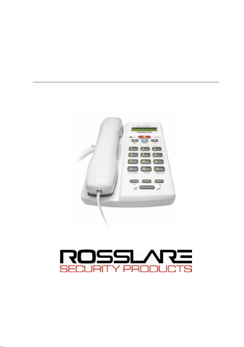
The SP-03V2 Elderly Care Telephone by Rosslare Enter p r ises, Lt d .
is the ideal wireless security system for home or small office
providing intrusion protection. The SP-03V2 Elderly Care
Telephone is also the wireless panel used to control, program
and operate the security monitoring and IVR (Interactive Voice
Response) messaging, with all of the regular features of a
home telephone.
The SP-03V2 Elderly Care Telephone uses the latest RF
technology and enables the smooth and easy operation of a
large number of security and communication options.
This manual contains the following sections:
• Telephone Description
• Making Telephone Calls
• Configuring the phone setup
• Programming the Pill Reminder
• Security Panel Behavior and Modes of Operation
• Emergency and Panic Functionality
Figure 1 The SP-03V2 Elderly Care Telephone
Page 8
Telephone Description
SP-03V2 User Manual
Page 7
2. Telephone Description
This chapter describes the following:
• Front Panel
• Front Panel Keys
• LED Indicators
• LCD Display
• Sound Indicators
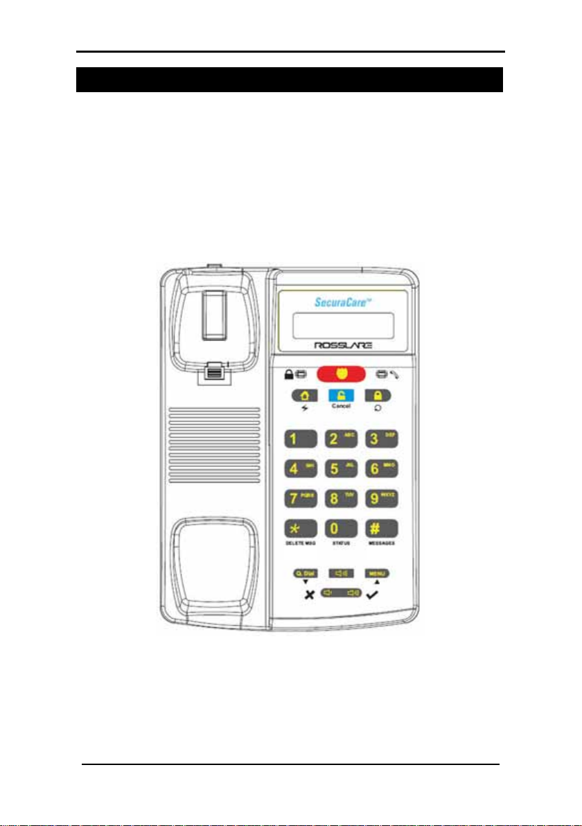
2.1 Front Panel
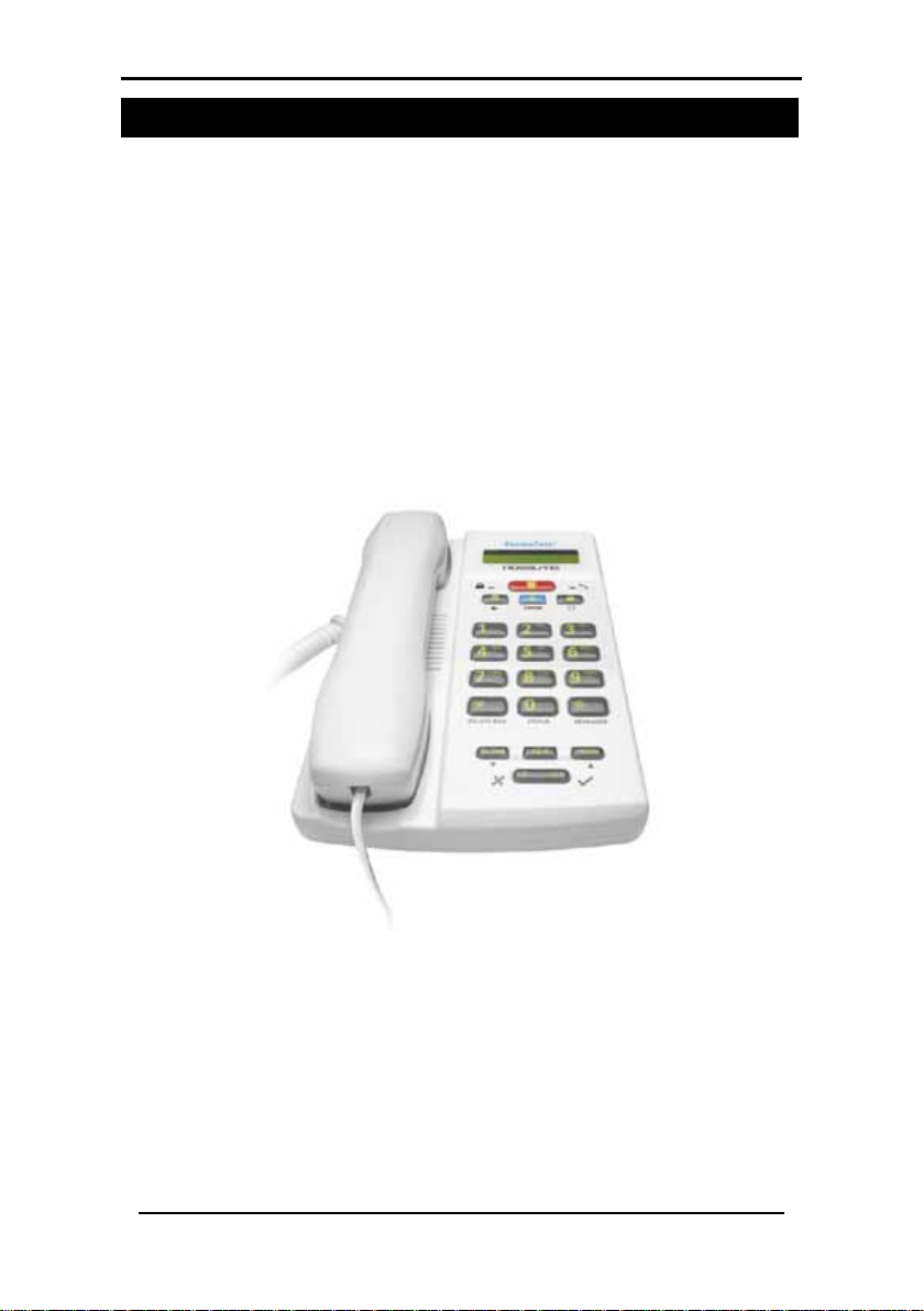
Figure 2: SP-03V2 Elderly Care Telephone Front View
The front panel is used as a standard keypad for making
regular telephone calls and is also used to enter information
when programming other functions including alarms and
emergency alerts.
Page 9
SP-03V2 User Manual
Page 8
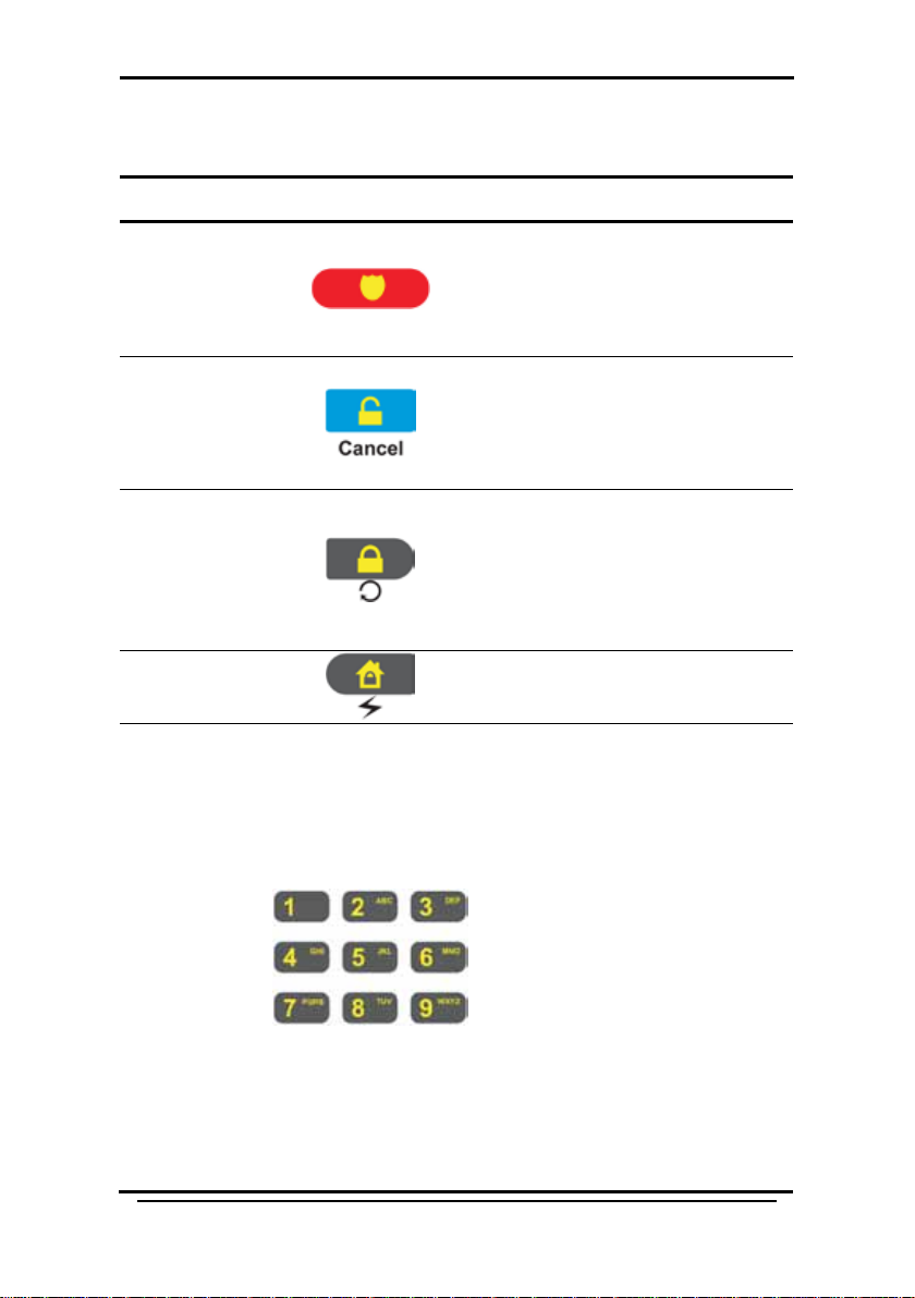
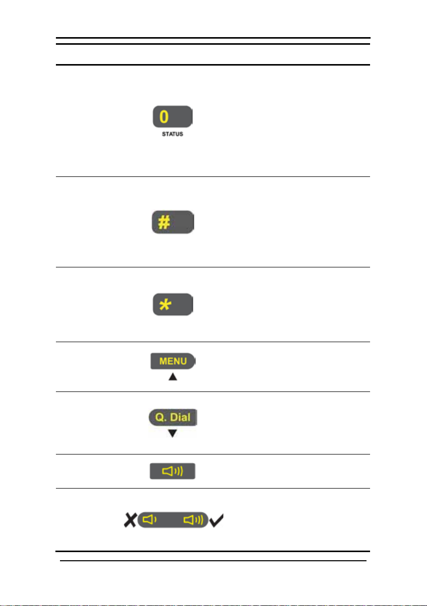
2.2 Front Panel Keys
Name
Key
Function
Alphanumeric
The keys on the front panel are as follows:
• Triggers an emergency
Emergency
Disarm/
Cancel
Arm (Away)/
Redial
call
• Sounds a standard panic
alarm
• Disarms the system when
armed (requires code)
• Cancels emergency calls
and actions
• Idle mode - Arms the
system in "Away" mode
(requires Code)
• Phone mode - Redials last
called telephone number
Telephone Description
Arm (Home)/
Flash
keys 1-9
In idle mode - Arms the system
in "Home" mode (requires code)
• Enter/edit numbers 1-9 to
dial or quick dial
• Enter alphanumeric
characters (keys 2-9 to
corresponding to the
indicated letters)
• When entering letters,
each push on the same
key changes the letter to
the next letter indicated
or number on the key. For
example 3 - D - E - F - 3
etc.
• During a call it sends a
DTMF code of the pressed
number during a call
Page 10
Telephone Description
SP-03V2 User Manual
Page 9
Name
Key
Function
# Key
Þ Key
Menu/Up
Quick
Speaker
Volume
0 Key
• Enter/edit number 0 to
dial or quick dial
• enters trouble display
which displays problems
experienced by the
system when trbl
indication appears on the
LCD
• Clears Access Codes
• Clears last entered digit in
Phone Number/Numeric
Value
• Transmits '#' DTMF code
during a Manual Call
• Enters a comma ',' as a
Dialing Delay in a Phone
Number (during editing)
• Transmits '*' DTMF code
during Manual Call
Dial/Down
• Accesses the Menu
• Navigates "Up" in the
menus
• Phone mode - Enter Quick
Dial mode
• Idle mode - Navigates
"Down" in the menus
• Switches the phone
speaker on or off
• Increase/decrease
speaker volume
• Enter No/Yes (same as
Cancel/Enter)
Page 11
Telephone Description
SP-03V2 User Manual
Page 10
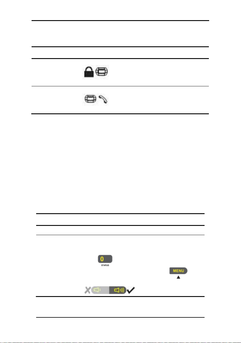
Name
LED
Function
Red
there is an entry or exit delay
(based on the beep rate).
Green – Handset is off the hook.
System S tatus
Description
Ready
Indicates that the system is ready for ar ming.
Indicates that the system is not ready fo r
button to see more details.
2.3 LED Indicators
The table below describes the various LED indicators.
– the system is armed.
Status Indicator
Off –the system is disa rmed.
Flashing –
Communication
Indicator
Off – commu n ic a tion is dis abled.
Flashing – communication is via a PC,
in phone mode speaker is on.
2.4 LCD Display
The LCD display clearly shows the system status in two rows,
displaying the system status and events.
When in idle mode the first line displays the system's time and
date while the second line shows the system status. For
example, the second line displays Ready.
System status is displayed on the left, while events are
displayed to the right of the system statuses. The event display
toggles every two seconds when there is more than one event.
The display options are described in the table below:
arming, and that there are zones which are
detecting somethi ng. These are active zones.
Not ready
Press to view active zones. If there is
more than one active zone, press
display the next active zone or press the
to
Page 12

Telephone Description
SP-03V2 User Manual
Page 11
Event Displ ay
Description
MEM
Sounds
Action
A key is pressed. This feature is activated by the
installer.
Long beep
Four short
minute
A key is not pressed for 30 seconds or more (except
current menu.
Short beep
every second
Nine short
Beeps
A chime is activated. The system supports three
chime is sounded when the zone is triggered.
The system has one or more of the following
problems:
• Low battery (system or sensor)
TRBL
• Power failure
• Supervision failure
• RF jamming
• Tamper (system or sensor)
There is an alarm in memory.
2.5 Sound Indicators
The system and keypad emit the following sounds:
Single beep
An invalid entry i s entered.
beeps a
Two short
beeps
Chime
Indicates that there is a problem.
This feature is activated by the installer.
during Test mode). The s y s tem automaticall y exits the
An exit/entry dela y is activated. A beep is sounded
every 0.5 seconds during the last 10 seconds of delay.
The system arms when one or more zones are active.
The installer must program this feature.
chime sounds which can be selected to be heard
when a zone is activated (violated) during disarming
or when receiving a status update. For example the
Page 13
Making Telephone Calls
SP-03V2 User Manual
Page 12
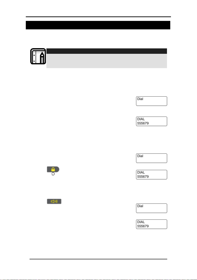
Note:
displayed.
and dial again.
1. Pick up the receiver. The dial tone is heard
displayed.
displayed. The call is initiated.
heard and the DIAL screen is displayed.
3. Making Telephone Calls
Although the SP-03V2 Elderly Care Telephone has many
features it still works as a standard phone.
When setting up the system telephone, use a comma (,) to
indicate a delay when dialing a number.
3.1 Standard Dialing
To make a call:
1. Pick up the receiver. The dial tone is heard
on the receiver and the DIAL screen is
2. Use the numeric keypad to enter the
telephone number. If a wrong key is
entered, place back the receiver, pickup
To call the same number agai n :
on the receiver and the DIAL screen is
2. Press
. The previous number is
To make a hands free call:
1. Press . A prompt for the telephone
number to call is heard. The dial tone is
2. Use the numeric keypad to enter the
telephone number.
Page 14
Making Telephone Calls
SP-03V2 User Manual
Page 13
displayed.
"Please enter code".
system returns to normal operating mode.
.
being set is displayed.
3.2 Quick Dialing
Commonly used numbers, or emergency numbers can be
stored on the phone. Each stored numbers is associated with a
Quick Dial Number. Each Quick Dial Number is represented by
the number 0 – 9 with an alphanumeric name of up to 16
characters.
The SP-03V2 Elderly Care Telephone allows storage of 10
memorized telephone numbers.
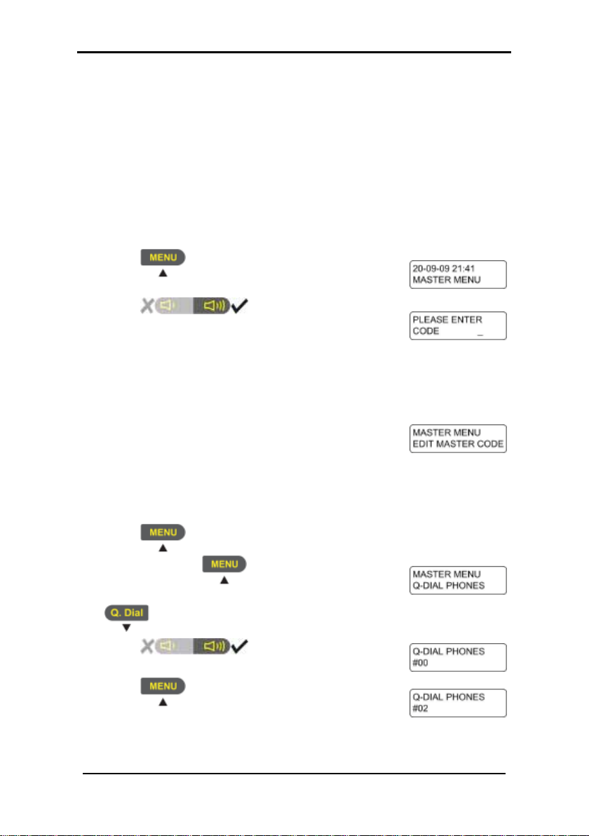
To set Quick Dial Numbers:
1. Press . The Master Menu option is
2. Press . The code prompt is
displayed and the system announces
3. Using the numeric keypad enter a valid user
or master code. While entering the code
each number entered is indicated by an "*".
On completing the code, the EDIT MASTER
CODE screen is displayed.
If the incorrect code is entered, the system
displays "Wrong Code, Please Try Again"
and announces "Illegal Code".
If there is no activity for 10 seconds, the
4. Press until the option Q-DIAL PHONES
is displayed. If
times, go back in the menus by pressing
5. Press . The Quick Dial
Number option is displayed.
6. Press until the Quick Dial Number
is pushed too many
Page 15
Making Telephone Calls
SP-03V2 User Manual
Page 14
Number is displayed.
Number is displayed.
Number is displayed.
. The option to enter the number
displayed.
Number is displayed.
number.
Number is displayed.
programmed.
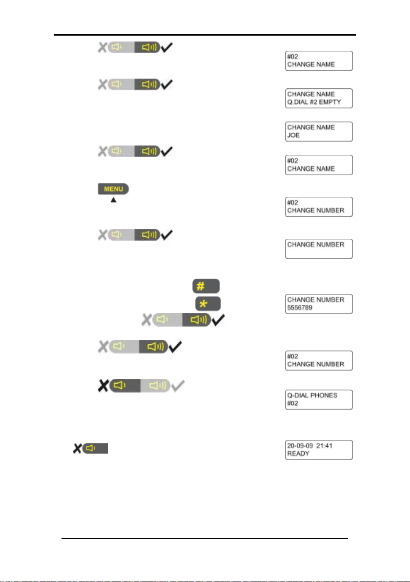
16. To store more Quick Dial Numbers repeat
operating mode.
7. Press . The option to enter
the name assigned to the Quick Dial
8. Press . The screen to enter
the name assigned to the Quick Dial
9. Enter the name associated with the Quick
Dial Number.
10. Press . The option to enter
the name assigned to the Quick Dial
11. Press
assigned to the Quick Dial Number is
12. Press . The screen to enter
the number assigned to the Quick Dial
13. Use the numeric keypad to enter the
telephone number. Press
the last entered digit. The
comma. Press
14. Press . The option to enter
the number assigned to the Quick Dial
15. Press to go back to step
6 where more Quick Dial Numbers can be
steps 7 – 15. To finish storing numbers, press
twice. The standard screen is
displayed and the system returns to normal
to delete
key inserts a
to save the
Page 16

Making Telephone Calls
SP-03V2 User Manual
Page 15
in slot #0 is displayed with the number.
required number is located.
To dial Quick Dial Numbers:
1. Press . The Quick Dial number stored
2. Press
and to scroll through
the stored Quick Dial numbers until the
3. Press
to initiate the call.
Page 17

Programming Interactive Voice Response
SP-03V2 User Manual
Page 16
entry code is made.
3. Using the numeric keypad enter a valid user or master
menu is opened.
4. Programming Interactive Voice Response
IVR (Interactive Voice Response) feature includes Voice
Assistance, where the SP-03V2 Elderly Care Telephone uses a
voice to prompt the user. An IVR session can be initiated either
by the system or though a remote private telephone call by
the user.
During voice menu mode, the system announces the menu
options and any relevant instructions.
To start an IVR Session by a remote telephone user:
1. Call the system's line telephone number. The system
answers the call after a preset number of rings. The system
plays the "Press Star” announcement and waits for the
to be pressed.
2. Press
to start the session. Once the connection is
made a site description is announced and a request for
code to start the session. The session is started and the IVR
To start an IVR Session by the system:
This option must be enabled by the technician who installed
the system. The session is usually started by a predefined event.
The system accesses a private number configured in the
system. Up to three private numbers can be programmed.
(See Setting Private Telephone Numbers, on page 23)
1. The system calls the first programmed private number. The
systems requests
approximately 50 seconds the system hangs up. The system
then attempts to call the private telephone number again.
If there is no response the system then attempts the second
private the predefined number of times, and if the system
still does not succeed, the third private number is
attempted.
is pressed. If there is no answer after
Page 18

Programming Interactive Voice Respo nse
SP-03V2 User Manual
Page 17
Option
Description
Enters the Voice Operation submenu. The private TwoWay V o ice feature must be enabled.
Option
Description
2. Press to start the session. Once the connection is
made a site description is announced and a request for
entry code is made.
3. Using the numeric keypad enter a valid user or master
code. The session is started and the IVR menu is opened.
The system switches to voice menu mode when a valid
master code is entered.
4.1 IVR Ge neral Options
The IVR menu has the following options:
Enters the Arming su bmenu.
Receives a status report.
Exits the menu and disconnects the system.
4.2 IVR Arming Submenu
The IVR Arming submenu has the following options:
Sets the panel status to "Arm Away".
Sets the panel status to "Arm Home".
Disarms the panel.
Returns to the previous menu.
When it is arming, the system announces its status only after the
exit delay timeout period.
Page 19

Programming Interactive Voice Response
SP-03V2 User Manual
Page 18
Option
Description
Option
Description
4.3 IVR Voice Operation Submenu
The IVR Voice Operation submenu has the following options:
Enables Two-way Voice Activation submenu.
Returns to the previous menu.
4.4 IVR Two-way Voice Activation Submenu
The IVR Two-way Voice Activation submenu has the following
options:
Enables listening in to the call.
Enables listening in and talking on the call.
4.5 Receiving IVR Status Report
On the IVR Arming submenu press . The report is heard on
the telephone.
Page 20

User Menu Options
SP-03V2 User Manual
Page 19
displayed.
3. Using the numeric keypad enter a valid
system returns to normal operating mode.
5. User Menu Options
Once the SP-03 Elderly Care Telephone has been installed
there are certain settings which are managed by the user. To
manage these settings the telephone provides a set of menus
which are displayed on the telephones display panel.
5.1 Accessing the User Menu
The User Menu is the base menu from which all the settings are
started. This is the only menu requiring a log in code or
password.
To open the User Menu:
1. Press . The Master Menu option is
2. Press
. The code prompt is
displayed.
master code. While entering the code
each number entered is indicated by an
"*". On completing the code, the EDIT
MASTER CODE screen is displayed.
If the incorrect code is entered, the system
announces "Illegal Code" and displays
"Wrong Code, Please Try Again".
If there is no activity for 10 seconds, the
Once in the MASTER MENU use the
browse the submenus. Press
or submenu item.
The sub menu options are as follows:
and keys to
to select a menu
Page 21

User Menu Options
SP-03V2 User Manual
Page 20
Option
Description
what is set as the user code.
User codes are only used to arm/disarm the
feature.
Up to 10 numbers can be stored as Quick
Dial numbers.
for emergency purposes.
Call and event logs can be cleared or
Certain preset security zones can be
bypassed when activating the alarm.
Note:
displayed.
Edit Master Code
User Codes
Set Date &Time
Private Numbers
The master code can be used no matter
system.
The system date and time is set. The system
time is used by the telephone for logging
calls, events and by the pill reminder
Private numbers ar e used by the system to
contact the user.
Q-Dial Phones
The telephone can automatically hang up
Forced Hang Up
Logs
and close a conversation in the event of an
emergency where the telephone is needed
viewed.
Bypass Options
5.2 Changing the Master Code
This feature is only for master users.
The default master code is 1234. Once the master code is
changed, the default code is Unusable.
To change the master code:
1. Press . The Master Menu option is
2. Press . The code prompt is
displayed.
Page 22

User Menu Options
SP-03V2 User Manual
Page 21
3. Using the numeric keypad enter a valid user
each number entered is indicated by an "*".
system returns to normal operating mode.
MASTER CODE screen is displayed.
The standard screen is
operating mode.
Note:
displayed.
master code. While entering the code each
number entered is indicated by an "*".
On completing the code, the EDIT MASTER CODE screen is
displayed. If the incorrect code is entered, the system will
or master code. While entering the code
On completing the code, the EDIT MASTER
CODE screen is displayed.
If the incorrect code is entered, the system
announces "Illegal Code" and displays
"Wrong Code, Please Try Again".
If there is no activity for 10 seconds, the
4. Press . The prompt to enter
the new master code is displayed.
5. Using the numeric keypad enter the new
master code and press
. The
master code is changed and the EDIT
6. Press .
displayed and the system returns to normal
5.3 Defini ng User Codes
Up to 16 users can be defined.
This feature can only be programmed by users with the
master code.
To define user codes:
1. Press . The Master Menu option is
2. Press . The code prompt is
displayed.
3. Using the numeric keypad enter a valid
Page 23

User Menu Options
SP-03V2 User Manual
Page 22
not accept it. If there is no activity for 10 seconds, the
system returns to normal operating mode.
displayed.
code being set.
displayed.
8. Using the numeric keypad enter the four
as required.
displayed and the system returns to
normal operating mode.
Note:
displayed.
While entering the code each number entered is indicated
by an "*".
4. Press . The USER CODES screen is
5. Press . The SELECT USER
CODE screen to set the first user code is
displayed.
6. Press and to scroll to the user
7. Press to select the user
code. The screen to enter the code is
digit user code and press .
Press
to delete an existing number.
The code is entered and the SELECT USE R
CODE screen is displayed. Repeat steps 7-8
9. Press twice. The standard
screen is
5.4 Setting Dat e and Time
This feature can only be programmed by users with the
To set the date and time:
1. Press . The Master Menu option is
2. Press
displayed.
3. Using the numeric keypad enter a valid master code.
master code.
. The code prompt is
Page 24

User Menu Options
SP-03V2 User Manual
Page 23
If the incorrect code is entered, the system announces
llegal Code" and displays "Wrong Code, Please Try Again".
normal operating mode.
screen is displayed.
displayed.
is displayed.
. The screen to set the
set.
to normal operating mode.
displayed.
"I
If there is no activity for 10 seconds, the system returns to
4. Press until the SET DATE & TIME
5. Press
screen is displayed.
6. Press
current time is displayed.
7. Enter the new time and press
8. Press
9. Press
day is displayed.
10. Press
11. Press
DAY OF THE WEEK screen is displayed.
12. Press
screen is displayed and the system returns
. The DAY OF THE WEEK screen
and to scroll to the day
. The ENTER TI ME
to set the time. The
. The ENTER TIME screen is
to set the day. The
twice. The standard
5.5 Setting Private Telephone Numbers
Up to three private telephone numbers can be set for use
when an event occurs. The private telephone number is called
by the system to alert the user.
To set private telephone numbers:
1. Press . The Master Menu option is
Page 25

User Menu Options
SP-03V2 User Manual
Page 24
3. Using the numeric keypad enter a valid user or master
"Illegal Code" and displays "Wrong Code, Please Try Again".
normal operating mode.
NUMBERS screen is displayed.
private number being set.
displayed.
Repeat steps 7-8 as required.
to normal operating mode.
2. Press . The code prompt is
displayed.
code. While entering the code each number entered is
indicated by an "*".
If the incorrect code is entered, the system announces
If there is no activity for 10 seconds, the system returns to
4. Press three times. The PRIVATE
5. Press
the number to set is displayed.
6. Press
7. Press
to set. The screen to enter the number is
8. Using the numeric keypad enter the
number and press
number is entered and the screen to
select the number to set is displayed.
9. Press
screen is displayed and the system returns
and to scroll to the
to delete an existing digit. The
. The screen to select
to select the number
. Press
twice. The standard
5.6 Viewing Logs
Event and history logs can be viewed.
There are three options available under Logs:
• History Log – Used to view the history log such as alarms,
trouble warnings, etc.
• Clear History Log – Used to clear the history log.
• Event Log – Used to view the event log.
Page 26

User Menu Options
SP-03V2 User Manual
Page 25
displayed.
"Illegal Code" and displays "Wrong Code, Please Try Again".
normal operating mode.
displayed.
screen is displayed.
indicated by the word PANEL.
system returns to normal operating mode.
To view the history logs:
1. Press . The Master Menu option is
2. Press
. The code prompt is
displayed.
3. Using the numeric keypad enter a valid user or master
code. While entering the code each number entered is
indicated by an "*".
If the incorrect code is entered, the system announces
If there is no activity for 10 seconds, the system returns to
4. Press until the LOGS screen is
5. Press
. The screen to select
the logs option to use is displayed.
6. Press
or toggling between
the Log options until the HISTORY LOG
7. Press
. The log is displayed.
8. Press
and to toggle
between the Log entries. Master events
are indicated by the word MASTER on the
bottom line of the screen, user events are
9. Press
three times. The
standard screen is displayed and the
Page 27

SP-03V2 User Manual
Page 26
To view the event logs:
displayed.
"Illegal Code" and displays "Wrong Code, Please Try Again".
normal operating mode.
displayed.
LOG screen is displayed.
word PANEL.
system returns to normal operating mode.
User Menu Options
1. Press . The Master Menu option is
2. Press
. The code prompt is
displayed.
3. Using the numeric keypad enter a valid user or master
code. While entering the code each number entered is
indicated by an "*".
If the incorrect code is entered, the system announces
If there is no activity for 10 seconds, the system returns to
4. Press until the LOGS screen is
5. Press
. The screen to select
the logs option to use.
6. Press
and to toggle
between the Log options u ntil the EVENT
7. Press
. The event log is
displayed.
8. Press
. The Event Time
Stamp is displayed.
9. Press
and to toggle between the Log entries.
Master events are indicated by the word MASTER on the
bottom line of the screen, user events are indicated by the
10. Press three times. The
standard screen is displayed and the
Page 28

Pill Reminder
SP-03V2 User Manual
Page 27
the screen.
DISABLED.
displayed.
normal operating mode.
6. Pill Reminder
Up to eight different pill reminders can be set. The setting
specifies the time to take each dosage, up to eight different
times for each day of the week.
There are four options to set as pill reminders:
• Activate the pill reminder.
• To set the number of times the alert is repeated.
• To set the pill reminder times.
• The failed reporting to the CMS.
To activate the pill reminder:
1. Press until the day is displayed on
2. Press
. The PROGRAM
REMINDER screen is displayed.
3. Press
. The FAIL REPORT
screen is displayed.
4. Press
. The screen to
enable/disable the pill reminder is
displayed.
5. Press
and to toggle
between the two options. The default is
6. Press
to enable the pill
reminder option. The FAIL REPORT screen is
7. Press
. The PROGRAM
REMINDER screen is displayed.
8. Press
. The EXIT screen is
displayed.
9. Press
. The standard screen
is displayed and the system returns to
Page 29

Pill Reminder
SP-03V2 User Manual
Page 28
the screen.
the pill reminder is displayed.
t is to
be repeated.
displayed.
normal operating mode.
the screen.
To set the number of times the alert is repeated:
1. Press until the day is displayed on
2. Press
REMINDER screen is displayed.
3. Press
screen is displayed.
4. Press
5. Press
screen is displayed.
6. Press
between the number of times the aler
7. Press
of alerts. The ALERT REPEAT screen is
8. Press
REMINDER screen is displayed.
9. Press
displayed.
10. Press
is displayed and the system returns to
. The screen to enable/disable
and to toggle
. The PROGRAM
. The FAIL REPORT
. The ALERT REPEAT
to select the number
. The PROGRAM
. The EXIT screen is
. The standard screen
To set the pill reminder times:
1. Press until the day is displayed on
2. Press
REMINDER screen is displayed.
3. Press
screen is displayed.
. The PROGRAM
. The FAIL REPORT
Page 30

Pill Reminder
SP-03V2 User Manual
Page 29
REMINDERS screen is displayed.
. The ENTER REMIND E R
eight reminders can be set.
The CLEAR REMINDER screen is displayed.
displayed.
to
REMINDER screen is displayed.
is displayed.
select the day of the week is displayed.
to be set.
displayed.
between the enable/disable options.
4. Press and until the SET
5. Press
# screen is displayed.
6. Press
and to toggle
between the alert reminder number. Up to
7. Press
. The screen to begin
entering the reminder details is displayed.
8. If there is already a reminder set and a
new reminder is required, the existing
reminder can be cleared. Press
to clear the reminder. The
CLEAR REMINDER confirmation screen is
9. Press
reminder deletion. Press
to confirm the
cancel the reminder deletion. The CLEAR
10. Press
11. Press
. The DAY OF THE WEEK screen
to select the day of
the week for the reminder. The screen to
12. Press
13. Press
and to scroll to the day
to select the day.
The screen to enable/disable the day is
14. Press
and to toggle
Page 31

SP-03V2 User Manual
Page 30
15. Press to enable/disable
displayed.
details is displayed.
displayed.
a comma.
dosage is displayed.
dosage is displayed.
dosage.
dosage is displayed.
between the enable/disable options.
displayed.
the day of the week for the reminder. The
screen to select the day of the week is
Pill Reminder
16. Press
. The DAY OF THE
WEEK screen is displayed.
17. Press
18. Press
. The screen to enter the pill
to enter the pill
name. The screen to enter the pill name is
19. Using the numeric keypad to enter the
telephone number. Press
the last entered digit. The
20. Press
. The screen to enter
to delete
key inserts
the pill details is displayed.
21. Press
22. Press
. The screen to enter the pill
to enter the pill
dosage. The screen to enter the pill
23. Press
and to select the
24. Press
dosage. The screen to enable/disable the
25. Press
and to toggle
26. Press
dosage. The screen to set the alert time is
to set the pill
to enable the
Page 32

Pill Reminder
SP-03V2 User Manual
Page 31
pill dosage is displayed.
normal operating mode.
27. Enter the alert time and press
. The screen to enter the
28. Press
until the EXIT screen
is displayed.
29. Press
. The standard screen
is displayed and the system returns to
Page 33

Security Panel Behavior and Modes of Operation
SP-03V2 User Manual
Page 32
7. Security Panel Behavior and Modes of
Operation
This chapter describes the operating conditions for the system
and instructs the user how to place the security system in its
various security operational modes.
7.1 Alarm Mode
The SP-03v2 system enters Alarm Mode according to the
various events, zone types and arming mode defined during
system setup.
7.1.1. Alarm Mode Armed
When armed the system monitors zones for any violations or
intrusion events. Any zone violation or intrusion detection puts
the system into Alarm Mode.
When there is some system failure or system inconsistencies the
system enters into Trouble Mode. If the system enters Trouble
Mode and the system is armed the system also enters Alarm
Mode.
Upon entering Alarm Mode, or when trouble conditions occur,
the system performs the following possible actions as defined
by the system installer during system setup.
Upon entering alarm mode, the system:
• Reports an event to the central station
• Performs other reporting (cellular, private phone)
• Activates a siren (silent, local siren, external siren)
• Uses backup/secondary reporting options
Page 34

Security Panel Behavior and Modes of Operation
SP-03V2 User Manual
Page 33
7.1.2. Alarm Mode Disarmed
When disarmed, the system enters into the following status:
• Alarm Mode for all 24 hour zones
• Alarms trigger only for panic, emergency, fire, 24H audible
and silent conditions.
In the Alarm Mode Disarmed state, the system continuously
checks zone status and remains in the Ready status. This Ready
status determines whether the system is ready to arm. The
system becomes Ready to Arm when zones are either closed
or bypassed, or Force Arming is enabled.
In all other cases, including if the No-Supervision of RF devices
parameter is enabled, the system status is Not Ready. In the
Not Ready condition, the system is unable to arm unless the
system has been configured to arming or if Force Arming is
enabled.
7.2 Arming O ptions
When the user enters a code or remote command, the system
responds as follows:
• If the code or command (armed away/home, disarmed)
is valid and correctly entered, the arming/disarming
operation succeeds. The system then sends the panel a
signal to sound a confirmation notification or generates a
confirmation sound on the local siren. This can be set to
either enabled or disabled. By default it is enabled.
• On entering a wrong code, the system enables immediate
code re-entry and also signals an error indication to the
user.
• Where there are 5 sequential wrong DISARM code entries,
the system ignores further attempts for 30 seconds before
accepting a new code entries.
Once armed, the system functions as follows:
• The system ignores arming commands, except Disarm,
through either panel, or remote during an alarm condition.
• The system sends error indication signals if zones are either
not ready or not bypassed (assuming that a bypass or
forced options are not enabled).
Page 35

Security Panel Behavior and Modes of Operation
SP-03V2 User Manual
Page 34
heard.
st
Delay time period.
displays solid red.
• The system exits the Alarm Mode if the alarm is triggered
by an alarm or tampering while the system was disarmed.
• The system enters Alarm Mode if any zone is violated
during entry and exit delay periods, unless the walkthrough
feature is enabled and the violated zones are defined as
walkthrough path.
To arm the system:
1. Press . A prompt to enter the code is
2. Enter the code. The code being entered is
indicated by “*”.
3. The panel starts beeping for the period
configured as the Exit Delay. The
indicator begins flashing red. The user mu
now exit the secure area within the Exit
4. The system is armed. The
indicator
7.2.1. System Home Arming
When configuring the system the installer can configure the
Arm Mode to HOME. This enables the user to enter the secured
area within the Entry Delay time and the system automatically
changes being in AWAY mode to HOME mode. The effect is
that all perimeter zones remain armed. During the Entry Delay
time, the system ignores zone violations. When the Entry Delay
time has ended, the system ignores interior zone violations.
Once the system is armed Home, it functions as follows:
• The system enters Alarm Mode immediately on a violation
of a perimeter type zone.
• The system activates an entry delay.
• The system enables switching between arming modes. If
the system is currently Armed Home, it accepts an Arming
Away command and switch modes without disarming.
When the user is at home, the alarm can be set for HOME
mode.
Page 36

Security Panel Behavior and Modes of Operation
SP-03V2 User Manual
Page 35
is heard.
indicator begins flashing red. The user must
Delay time period.
To arm the system to HOME mode:
1. Press . A prompt to enter the code
2. Enter the code. The code being entered is
indicated by “*”.
3. The panel starts beeping for the period
configured as the Exit Delay. The
now exit the secure area within the Exit
4. The system is armed. The
displays solid red.
indicator
7.2.2. System Away Mod e
In AWAY mode, the system enters Alarm Mode if there is any
zone violation, regardless of perimeter or interior type.
7.2.3. Instant Arming
If Instant Arming mode is enabled (by the installer, during
configuration), the system will skip the exit delay as well as
cancel the entry delay configured, and will initiate the Alarm
instantly causing an alarm to go off upon violation of any zone.
To instantly arm the system:
1. Verify that the system is ready for arming.
2. Press either the Home or the Away arming key.
3. Enter your user code.
4. Press the same arming key once again.
7.2.4. Forced Arming
If Forced Arming is enabled, the system is able to arm when
zones are in violation (open) but not defined as bypassed. The
system treats zones of this type automatically as bypassed
zones for the arming period. These bypassed definitions expire
Page 37

Security Panel Behavior and Modes of Operation
SP-03V2 User Manual
Page 36
. A prompt to enter the code is
heard.
either upon disarming or once the zones are closed or
supervised (again) during the arming period.
The system acknowledges this condition by indicating a bypass
state when armed.
Depending on how the feature is defined during setup, a
report can be sent to the central station.
By default Forced Arming is disabled and is enabled by the
installer during system setup.
7.2.5. Quick Arming
Setting this parameter ON allows AWAY arming without code
entry. The system does not accept home arming when already
armed AWAY. When Quick Arming is enabled (during setup), a
long press on the AWAY arming button on the panel activates
Quick Arming.
By default Quick Arming is OFF and is set to ON by the installer
during system setup.
7.3 Disarming Process
Users can disarm an armed system by entering their code using
the panel, or using an RF keys/remotes.
Disarming causes the system to function as follows:
• Disarming a system both disarms it and stops an alarm
condition.
• When an alarm condition occurs during the disarming
process, the system triggers a full alarm. The alarm stops on
the next disarming operation.
To disarm the system:
1. Press
2. Enter the code. The code being entered is
indicated by “*”.
3. The system is disarmed.
Page 38

Security Panel Behavior and Modes of Operation
SP-03V2 User Manual
Page 37
Note:
displayed.
7.4 Bypass/Un-bypass Zone
The SP-03v2 system can be set to enable or disable zone
bypass. In auto bypass, the system functions as follows:
• If disabled (default) and zones are opened (doors,
windows) or unsupervised, the system does not allow
arming until all zones are closed. All incoming detections
are handled according to the selected alarm options for
zone type and setting.
• Each zone can be set as bypassed. The system ignores
incoming detections from a bypassed zone, and is able to
arm regardless of their condition.
• Zone bypassing behavior is dependent on the general
system bypass enable setting.
7.4.1. Setting Zone Bypass
When the system is installed, the secured area is divided in up
to 16 security zones. Each zone is set by the person installing
the system.
When arming the system certain zones can be bypassed. This is
used to deal with various situations, such as when the sensor
battery is low and sends an event, or when the system is armed
while someone is still on the premises.
This feature is available to Use r and Master level users,
and is only active if it is enable d b y th e installer.
Up to 16 zones can be bypassed when arming the system.
To define the bypass zones:
1. Press . The Master Menu option is
2. Press
displayed.
. The code prompt is
Page 39

Security Panel Behavior and Modes of Operation
SP-03V2 User Manual
Page 38
3. Using the numeric keypad enter a valid user or master
"Illegal Code" and displays "Wrong Code, Please Try Again".
normal operating mode.
screen is displayed.
BYPASS MAP is displayed.
to select the zone.
to select the option.
to normal operating mode.
displayed.
code. While entering the code each number entered is
indicated by an "*".
If the incorrect code is entered, the system announces
If there is no activity for 10 seconds, the system returns to
4. Press until the BYPASS OPTIONS
5. Press
and to toggle
between the bypass options until the SET
6. Press
. The screen to select
the zone to bypass is displayed.
7. Press
and to toggle
between the zone to select or by entering
the zone number 01 - 16. Press
8. Press
and to toggle
between the zone bypass options. Press
9. Press
until the standard
screen is displayed and the system returns
To clear the bypass zone s:
1. Press . The Master Menu option is
2. Press
. The code prompt is
displayed.
Page 40

Security Panel Behavior and Modes of Operation
SP-03V2 User Manual
Page 39
3. Using the numeric keypad enter a valid user or master
"Illegal Code" and displays "Wrong Code, Please Try Again".
normal operating mode.
screen is displayed.
CLEAR BYPASS MAP is displayed.
displayed.
to select the zone.
to select the option.
to normal operating mode.
displayed.
code. While entering the code each number entered is
indicated by an "*".
If the incorrect code is entered, the system announces
If there is no activity for 10 seconds, the system returns to
4. Press until the BYPASS OPTIONS
5. Press
and to toggle
between the bypass options until the
6. Press
. The screen to select
the bypassed zone to be cleared is
7. Press
and to toggle
between the bypassed zone numbers or
by entering the zone number 01 - 16. Press
8. Press
and to toggle
between the zone bypass options. Press
9. Press
until the standard
screen is displayed and the system returns
To activate the bypass zones:
1. Press . The Master Menu option is
2. Press
. The code prompt is
displayed.
Page 41

Security Panel Behavior and Modes of Operation
SP-03V2 User Manual
Page 40
3. Using the numeric keypad enter a valid user or master
"Illegal Code" and displays "Wrong Code, Please Try Again".
normal operating mode.
screen is displayed.
ACTIVATION is displayed.
to select the zone.
to normal operating mode.
condition.
code. While entering the code each number entered is
indicated by an "*".
If the incorrect code is entered, the system announces
If there is no activity for 10 seconds, the system returns to
4. Press until the BYPASS OPTIONS
5. Press
and to toggle
between the bypass options until the SET
6. Press
. The screen to select
the zone to be activated is displayed.
7. Press
and to toggle
between the zones to activate or by
entering the zone number 01 - 16. Press
8. Press
until the standard
screen is displayed and the system returns
Note:
If the system is armed the Bypass indicator and the
bypassed zones flash briefly before entering the armed
7.5 Entry/Exit Dela y Options
Entry and Exit actions delay the alarm mode and allow the
system to ignore zone violations, as described below.
7.5.1. Entry Delay
Entry delay allows the user time to open the door and reach
the panel to disarm the system.
Page 42

Security Panel Behavior and Modes of Operation
SP-03V2 User Manual
Page 41
If a zone of type Delay is violated while the system is armed
(except Instant Arming), the system does not enter Alarm
Mode during the Entry Delay period setting. If the delay period
finishes and the system still has not been disarmed, the system
enters Alarm Mode.
During Entry Delay, the system signals the panel to sound
warning beeps at two rates: slower rate and faster rate during
the last 10 seconds of the delay period.
The Entry Delay period is configurable from 1 second up until 99
seconds.
The default Delay period is 30 seconds.
7.5.2. 3.6.2. Exit Delay
Exit delay allows the user time to reach the door from the
panel when arming the system upon exit.
When arming a panel, the system ignores zone violations
during the Exit Delay period. Once the delay period is finished
the system enters armed mode.
The system may be disarmed during the Exit Delay period.
During Exit Delay, the system signals the panel to sound
warning beeps at two rates: slower rate and faster rate during
the last 10 seconds of the delay period.
The Exit Delay period is configurable from 1 second up until 99
seconds.
The default Exit Delay period is 30 seconds.
Page 43

Emergency and Panic Functionality
SP-03V2 User Manual
Page 42
8. Emergency and Panic Functionality
8.1 Siren
There are two siren type, the Internal siren which is from the
panel, and the Emergency siren which is set up and configured
by the installer.
• Internal Siren – This is used in an emergency situation
where the user needs to urgently contact the Control
Center and is activated by pushing the Emergency button
on the panel.
• Exter n al Si r en – The External siren is activated upon alarm,
emergency or violating a 24-hour zone, siren timeout is set
by the installer and turns off upon the disarm command
being entered.
The siren also features momentarily pulses (Squawk) for the
following events that can be enable according to the
requirements to:
o Arm Away (single pulse)
o Arm Home (single pulse)
o Disarm (dual pulse)
o Emergency alarm
o Trouble alert
8.2 Performing an Emergency Call
The SP-03v2 system enables the definition of an emergency
number (during installation) that is called when the user triggers
the emergency function.
To activate the emergency function:
1. Press for 2 or more seconds.
The system executes an emergency response according to the
panel’s emergency definitions, as set up during installation.
Typical responses include:
• Activating the sounder at any of the function options
• Reports an Emergency Event to the central station
• Reports to private telephone
Page 44

Emergency and Panic Functionality
SP-03V2 User Manual
Page 43
displayed.
The system responds to the panic event regardless of the
systems arming condition. Once a Panic alarm has been
entered, the system can be reset by disarming.
To reset the system by disarming:
1. Press . A prompt to enter the code is heard.
2. Enter the code. The code being entered is indicated by
“*”.
8.3 Entering th e Dur es s Cod e
The SP-03v2 system provides a duress code function that is
used to disarm the system when it is under threat. The specific
and unique code is defined during installation and given to the
user to memorize.
Once entered, the system immediately reports a duress
situation (Contact ID)—without entering the alarm mode or
activating the sounder and outputs. The silent alarm
generated acts as an ‘Ambush’ to report that the user is being
forced to disarm the system.
When the system receives a Duress alarm from the panel, the
system sends a DURESS alarm report to the central station and
to private phone numbers as defined, however no alarm is
sounded.
8.4 Enabling Fo rc ed Ha ng up
In an emergency a telephone call can be forcibly terminated
to allow for emergency options to be made available.
By default this feature is disabled.
To enable forced Hang Up:
1. Press . The Master Menu option is
2. Press
displayed.
. The code prompt is
Page 45

Emergency and Panic Functionality
SP-03V2 User Manual
Page 44
3. Using the numeric keypad enter a valid user or master
"Illegal Code" and displays "Wrong Code, Please Try Again".
normal operating mode.
screen is displayed.
displayed.
between the two options.
DURATION screen is displayed.
8. Using the numeric keypad set the time to
can be set.
. The standard screen
normal operating mode.
code. While entering the code each number entered is
indicated by an "*".
If the incorrect code is entered, the system announces
If there is no activity for 10 seconds, the system returns to
4. Press until the FORCED HANGUP
5. Press
. The screen to
enable/disable forced hang up is
6. Press
7. Press
and to toggle
to set the forced
Hang Up feature. If DISABLED is selected
the standard FORCED HANGUP screen is
displayed. If ENABLED is selected the
force the phone to remain out of use for
standard telephone calls. Up to 20 minutes
9. Press
to set time. The
FORCED HANGUP screen is displayed.
10. Press
is displayed and the system returns to
Page 46

Limited Warranty
SP-03V2 User Manual
Page 45
Appendix A. Limited Warranty
ROSSLARE ENT ER PR ISES LIMITED S (Rosslare) TWO YEARS LIMITED
WARRANTY is applicable worldwide. This warranty supersedes any other warranty.
Rosslare's TWO YEARS LIMITED WARRANTY is subject to the following conditions:
Warranty
Warranty of Rosslare's products extends to the original purchaser (Customer) of the
Rosslare product and is not transferable.
Products Covered By This Warranty and Duration
ROSSLARE ENTERPRISES LTD. AND / OR SUBSIDIARIES (ROSSLARE) warrants
that the SP-03V2 Advanced Wireless Phone system panel, to be free from defects in
materials and assembly in the course of normal use and service. The warranty period
commences with the date of shipment to the original purchaser and extends for a
period of 2 years (24 Months).
Warranty Remedy Coverage
In the event of a breach of warranty, ROSSLARE will credit Customer with the price of
the Product paid by Customer, provided that the warranty claim is delivered to
ROSSLARE by the Customer during the warranty period in accordance with the terms
of this warranty. Unless otherwise requested by ROSSLARE ENTERPRISES LTD.
AND / OR SUBSIDIARIES representative, return of the failed product(s) is not
immediately required.
If ROSSLARE has not contacted the Customer within a sixty (60) day holding period
following the delivery of the warranty claim, Customer will not be required to return the
failed product(s). All returned Product(s), as may be requested at ROSSLARE
ENTERPRISES LTD. AND /OR SUBSIDIARY’S sole discretion, shall become the
property of ROSSL ARE ENTERPRISES LTD. AND /OR SUBSIDIARIES.
To exercise the warranty, the user must contact Rosslare Enterprises Ltd. to obtain an
RMA number after which, the product must be returned to the Manufacturer freight
prepaid and insured
In the event ROSSLARE selects to perform a product evaluation within the sixty (60)
day holding period and no defect is found, a minimum US$ 50.00 or equivalent charge
will be applied to each Product for labor required in the evaluation.
Rosslare will repair or replace, at its discretion, any product that under normal
conditions of use and service proves to be defective in material or workmanship. No
charge will be applied for labor or parts with respect to defects covered by this
warranty, provided that the work is done by Rosslare or a Rosslare authorized service
center.
Page 47

Limited Warranty
SP-03V2 User Manual
Page 46
Exclusions and Limitations
ROSSLARE shall not be responsible or liable for any damage or loss resulting from
the operation or performance of any Product or any systems in which a Product is
incorporated. This warranty shall not extend to any ancillary equipment not furnished
by ROSSLARE, which is attached to or used in conjunction with a Product, or to any
Product that is used with any ancillary equipment, which is not furnished by
ROSSLARE.
This warranty does not cover expenses incurred in the transportation, freight cost to
the repair center, removal or reinstallation of the product, whether or not proven
defective.
Specifically excluded from this warranty are any failures resulting from Customer's
improper testing, operation, installation, or damage resulting from use of the Product
in other than its normal and customary manner, or any maintenance, modification,
alteration, or adjustment or any type of abuse, neglect, accident, misuse, improper
operation, normal wear, defects or damage due to lightning or other electrical
discharge. This warranty does not cover repair or replacement where normal use has
exhausted the life of a part or instrument, or any modification or abuse of, or
tampering with, the Product if Product disassembled or repaired in such a manner as
to adversely affect performance or prevent adequate inspection and testing to verify
any warranty claim.
ROSSLARE does not warrant the installation, maintenance, or service of the Product.
Service life of the product is dependent upon the care it receives and the conditions
under which it has to operate.
In no event shall Rosslare be liable for incidental or consequential damages.
Limited Warranty Terms
THIS WARRANTY SETS FORTH THE FULL EXTENT OF ROSSLARE ENTERPRISES
. AND IT’S SUBSIDIARIES’ WARRANTY
LTD
THE TERMS OF THIS WARRANTY MAY NOT BE VARIED BY ANY PERSON, WHETHER
OR NOT PURPORTING TO REPRESENT OR ACT ON BEHALF OF ROSSLARE
THIS LIMITED WARRANTY IS PROVIDED IN LIEU OF ALL OTHER WARRANTIES. ALL
OTHER WARRANTIES EXPRESSED OR IMPLIED
IMPLIED WARRANTIES OF MERCHANTABILITY AND FITNESS FOR A PARTICULAR
PURPOSE
IN NO EVENT SHALL ROSSLARE BE LIABLE FOR DAMAGES IN EXCESS OF THE
PURCHASE PRICE OF THE PRODUCT
CONSEQUENTIAL OR SPECIAL DAMAGES
OF USE
PROFITS
PRODUCT
DISCLAIMED BY LAW
THIS WARRANTY SHALL BECOME NULL AND VOID IN THE EVENT OF A VIOLATION
OF THE PROVISIONS OF THIS LIMITED WARRANTY
, ARE SPECIFICALLY EXCLUDED.
, OR FOR ANY OTHER INCIDENTAL,
, LOSS OF TIME, COMMERCIAL LOSS, INCONVENIENCE, AND LOSS OF
, ARISING OUT OF THE INSTALLATION, USE, OR INABILITY TO USE SUCH
, TO THE FULLEST EXTENT THAT ANY SUCH LOSS OR DAMAGE MAY BE
.
, INCLUDING WITHOUT LIMITATION,
, INCLUDING BUT NOT LIMITED TO LOSS
.
.
Page 48

Technical Support
SP-03V2 User Manual
Page 47
Appendix B. Technical Support
Asia Pacific, Middle East, Africa
Rosslare Security Products Headquarters
905-912 Wing Fat Industrial Bldg,
12 Wang Tai Road,
Kowloon Bay Hong Kong
Tel: +852 2795-5630
Fax: +852 2795-1508
support.apac@rosslaresecurity.com
E-mail:
United States and Canada
1600 Hart Court, Suite 103
Southlake, TX, USA 76092
Toll Free: +1-866-632-1101
Local: +1-817-305-0006
Fax: +1-817-305-0069
support.na@rosslaresecurity.com
E-mail:
Europe
Global Tech nical Support & Training Center
HaMelecha 2 2
Rosh HaAyin, Israel 48091
Tel: +972 3 938-6838
Fax: +972 3 938-6830
support.eu@rosslaresecurity.com
E-mail:
South America
Presbitero Actis 555, Oficina 31.
San Isidro. Buenos Aires. Argentina
Tel: +5411-5273-6383
Tel: +305-921-9919
support.la@rosslaresecurity.com
E-mail:
Web Site:
www.rosslaresecurity.com
 Loading...