

Page 1
SA-01PW
Digital Hardwired Pet Immune
PIR Motion Detector
Installation Manual
1
1. Introduction
The SA-01PW Digital Hardwired PET immune PIR motion detector is
a high-performance intrusion sensor with advanced design ideal for
residential and commercial applications.
The PIR senses slight motion within a coverage pattern by detecting
infrared energy with a pyroelectric sensor and with a unique fuzzy
logic algorithm. Serving as an anti-intrusion sensor, the PIR can
monitor open space within its line of sight while ignoring house pets
and other small animals, thus reducing false alarms significantly.
The SA-01PW is supplied with a cover tamper to detect tampering
with the sensor if the case is opened.
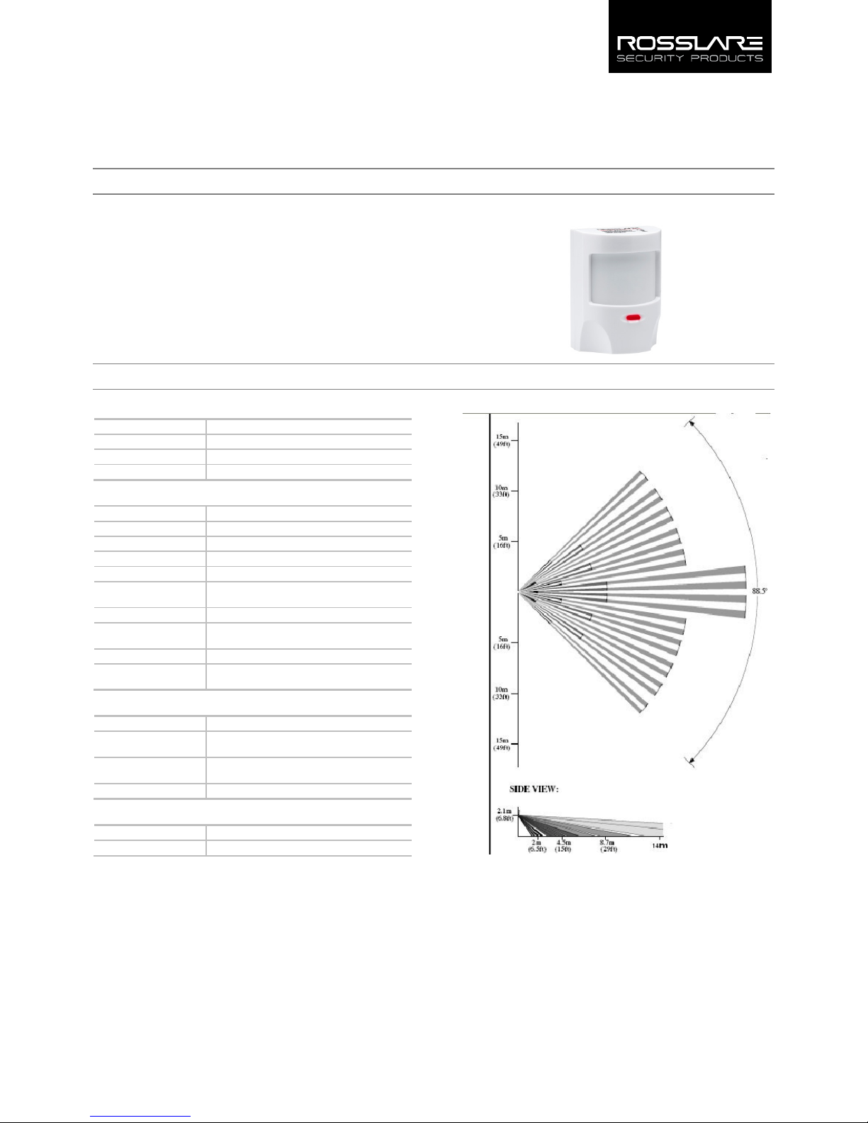
Figure 1: SA-01PW
2. Technical Specifications
2.1 Optical Characteristics
Lens Type
Pet immune multi-zone, high density Polytilan type
Optical Filter
White light protection
Max. Coverage
14 x 14 m (46 x 46 ft)
Vertical Adjustment
By slot (+/- 2°)
2.2 Electrical Characteristics
Input Power
Nominal 12 VDC 10 mA (9 to 16 V)
Detector Type
Dual pyro IR element (IR filter 5 µm ÷ 14 µm)
Alarm Signaling
Red LED 2 seconds on (EN/DIS jumper)
Sensitivity
2 levels of fuzzy logic (jumper setting)
Alarm Output
Solid states relay (SSR) N.C. (35 V/100 mA max)
Speed Detect 0.2 m/s ÷ 5 m/s, ∆t = 1.1°C (0.66 ft/s ÷ 16.4 ft/s,
∆t = 2°F)
Pet Immune
Up to 25 kg
Temperature
Compensation
Digital dual slope (+/- 1°C)
Tamper Switches
Cover tamper
Supervisory Signals
Electronic malfunction or temperature out of
range is indicated by a flashing LED
2.3 Environmental Characteristics
Operating Environment
Indoor use only
Operating Temperature
Range
-10°C to 60°C (14°F to 140°F)
Operating Humidity
Range
0 to 95% (non-condensing)
RFI Protection
>20 V/m up to 1000 MHz
2.4 Physical Characteristics
Dimensions
90 x 65 x 52 mm (3.5 x 2.5 x 2.2 in.)
Weight
84.2 g (2.97 oz.)
Figure 2: Lens Top and Side View
Page 2
2
3. General Features
These are the main features of the SA-01PW:
Advanced micro-controller electronics: 10-bit A-to-D and
advanced algorithms for superior movement speed spectrum
analysis.
Shielded dual-element pyro: Inside a dust-proof chamber
designed to reduce thermal changes and insect protection.
Two levels of sensitivity: Normal and harsh environments, by
jumper selection.
Input/output Line protection: For added resistance to
transient shock, ESD, and RFI interference.
Adjustable height calibration of PCB: The detector can be
adjusted and placed at any height from 1.8 to 2.3 m.
Cover tamper switch: Protection against opening the cover for
higher security.
Walk Test mode: Detection is indicated by a red LED (enabled
or disabled) with an internal jumper for additional security.
Energy detection system: By using fuzzy logic algorithms,
detection is improved and false alarms are reduced.
Power level discriminator: Special lens combined with a
power algorithm ignores small to medium-sized animals while
maintaining a high level of human detection.
Environment temperature compensation: Maintains
constant detection capability.
Adaptive filter: Compensates for changes in a detected
object’s speed.
Continuous monitoring: Sends visual alerts in case of
malfunction (digital and analog) and temperature alerts if the
environment temperature is out of range.
Solid state relay: Provides a nearly unlimited lifespan, EMC
resistance, and silent operation.
Digital Electrical and Magnetic Protection: Distinguishes
between electrical interference and real temperature changes.
4. Pet Immune Feature
The SP-01PW is immune from the following interferences:
One dog up to 25 kg
Two dogs of up to 20 kg each
Several cats
Unlimited number of small animals such as hamsters, birds,
rodents, and so on.
These are only guide lines; there may be some tolerance regarding
the size and weight of the animals monitored. For example, a shorthaired, dark colored canine appears bigger than a long-haired, light
colored canine. As a rule of thumb, please add 2-3 kg for each
attribute to calculate an animal’s weight when installing the
detector.
5. Installation
5.1 False Alarm Reduction Effort
To reduce false alarms caused by detector installation:
AVOID placing the PIR facing windows or in direct sunlight as
this heat energy can cause false alarms.
AVOID wiring of the SA-01PW in such a way that it is parallel to
and sitting close to 110 VAC or 220 VAC transmission
equipment or mains power line.
AVOID placing near or over heat and air ducts, ovens, heat
sources, radiators, and air conditioners as this may cause a false
detection.
AVOID placing near PL lamps, electrical ballasts, above cookers,
and ovens, and above steam sources.
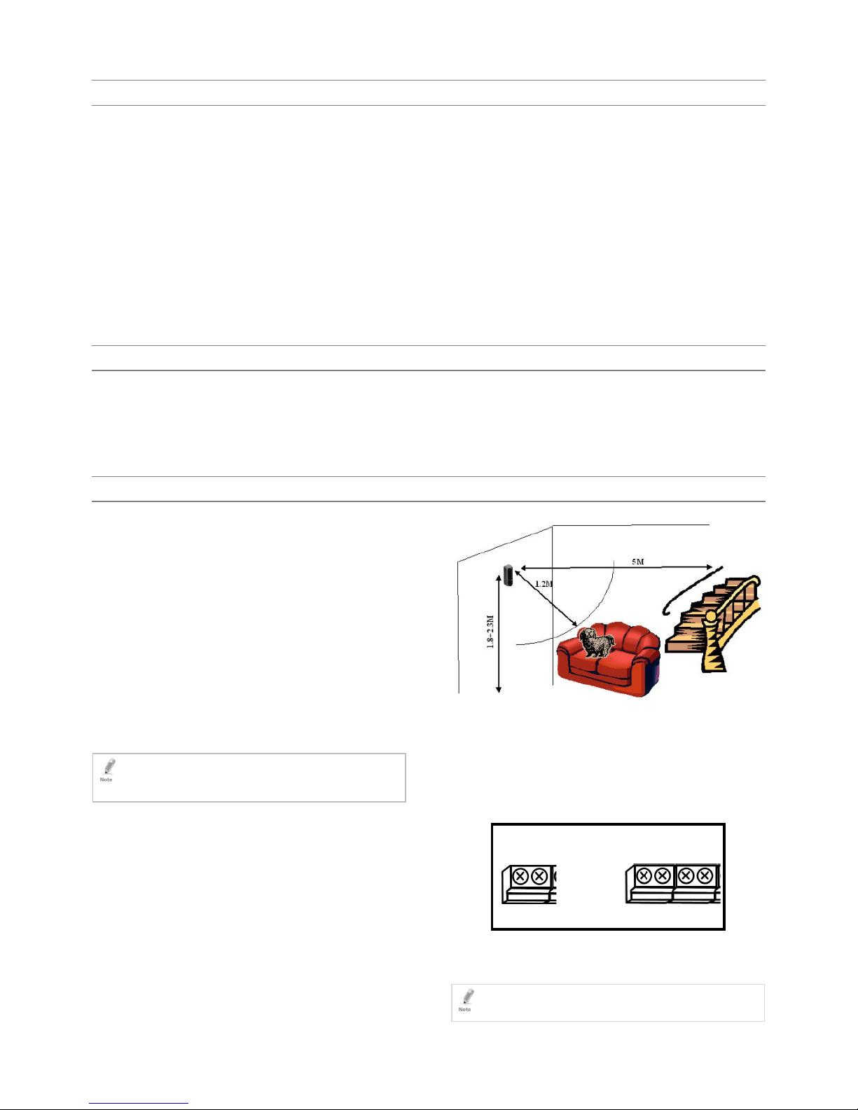
AVOID placing the detector where the house pet can be
within1.2 m, like a sofa, and less than 5 m from stairs and such
where the animal can climb (see Figure 3).
NEVER touch the pyroelectric sensor on the PCB, as this causes
permanent damage and loss of sensitivity.
PIR works according to a field of view and cannot detect
through walls. Avoid placing near obstructions such as large
plants, curtains, behind open doors, and continuously
moving objects.
5.2 Selecting the Physical Location
To select the best physical location to install the PIR:
1. Select a corner or a flat wall within a room or hallway between
1.8 and 2.3 m that best matches the criteria in Section 5.1 (see
Figure 3).
2. Ensure that the PIR is mounted on a non-moving, non-vibrating
surface, or in a corner of the room.
3. Mount the PIR in the location.
4. After the installation, perform a walk test from the mounting
location to ensure that the sensor pattern can detect within the
coverage area (see Section 7).
Figure 3: SA-01PW Installation Guidelines with Pets Present
5.3 Wiring Information
The SA-01PW is wired using a terminal block with binding posts that
are located on the front of the PCB and are opened using a thin
Philips head screwdriver or a flat head screwdriver.
The terminal block consists of two parts: on the right two normally
closed alarm relay binding posts followed by two tamper binding
posts and on the left a + and – 12 VDC binding post (Figure 4).
Figure 4: Terminal Blocks
To wire the SA-01AW:
1. Connect all the signaling cables.
2. Wire the power.
When laying wires to the control panel ensure that they are
not in parallel with high voltage mains or other radiation
emitting equipment as this may cause false alarms.
Alarm
N.C RLY
Tamper
GND +12VDC
To panel
From panel
Page 3

3
5.4 Mounting the PIR
The SA-01PW PIR is designed to be mounted onto a flat wall surface
or to a corner.
To mount the PIR to a flat surface:
1. Remove the PCB from the back case (see Figure 5)
2. Remove the knockouts from the back case, labeled “B” by using
a sharp tool or using a nail.
3. Affix the four screws onto the wall.
4. Replace the PCB and tighten the PCB locking screw.
5. Set the jumpers (refer to Section 6).
6. Pull out the paper strip located over one battery pole. This will
energize the detector.
7. Replace the top cover of the PIR.
The detector goes into test mode indicated by the LED flashing
for about 90 seconds. After a successful test, the LED goes off.
At this stage it is ready for a Walk Test.
Figure 5: Inside the Plastic Case – Back
6. Jumpers Setting
6.1 Setting the Sensitivity (JP2)
SA-01PW has two jumpers JP1, and JP2 to set the operation
method of the PIR. Insert a jumper to activate the desired setting.
To prevent false alarms caused by house pet or harsh environments
two sensitivity modes were designated:
Low – For harsh environments and where the total pet’s weight
is more than 25 kg
Medium – For normal usage
To set the jumpers:
Low – Jumper on pins 1 and 2
Medium – Jumper off
6.2 Setting LED Enable/Disable
You can disable the LED activity during Alarms by using the JP2
jumper.
When the jumper is on, the LED is enabled.
When the jumper is off, the LED is disabled.
LED disabled – no jumper
LED enabled – with jumper
For security reasons, after a successful Walk Test, the jumper should
be taken out.
In both cases, the LED remains active for all trouble annunciations.
6.3 Vertical Calibration
If the SA-01PW PIR is to be mounted at a height above 2.1 m or
below 1.9 m, calibrate the PCB by moving the PCB up or down in
the PIR housing accordingly before fixing it. The calibration scale on
the PCB and the calibration marker on the PIR housing help you
achieve the optimum calibration setting.
Figure 6: Calibration Scale
The PCB mounting height calibration scale is on the right hand side
of the top of
the PCB. Set the height using the line on the side of the
housing (Figure 7).
If mounting the PIR above 2.1 m, move the PCB (+) up in the PIR
housing so that the calibration marker is parallel to a + scale (for
example: 2). This ensures that the detection area is focused closer to
the unit.
If mounting the PIR below 1.9 m, move the PCB down (-) in the PIR
housing so that the calibration marker is parallel to a - scale (for
example: -2). This ensures that the detection area is focused further
from the unit, therefore maximizing detection range.
Either way, refrain from installing the detector higher than 2.3 m or
lower than 1.8 m since it reduces efficiency.
Figure 7: Front of PCB
0
-2
-4
2
4
Page 4

4
7. Testing the Detector
The SA-01PW PIR has a built-in Walk Test function where the LED of
the PIR is enabled. This test is used to check the detection of the PIR
and the coverage pattern and to adjust the height calibration
accordingly.
To perform a Walk Test:
1. Ensure all of the settings in the PIR are adjusted as necessary for
the location according to the installation instructions above, and
that the PIR case is closed and the locking screw is firm.
2. Ensure the LED jumper is installed and then close the cover of the
PIR.
3. Apply power to the unit. The LED flashes on for 2 seconds and off
for 2 seconds for a period of 1 minute. During this time, all PIR
paths are being self tested. After the test is successful, the LED
switches off. At this point, a Walk Test can be performed.
4. For first time power up, allow the system to stabilize for
approximately 5 minutes before conducting the Walk Test.
5. With the LED enabled, the LED flashes every time the detector
detects motion. There is a 2-second wait period before the next
detection.
6. It is recommended that the installer test the detection by going
over the protected area and seeing that the detection pattern is
good.
7. Take out the LED jumper after a successful Walk Test.
8. Signaling
The LED on the front of the SA-01PW is used to send several signals
to the user. The following table describes the signals for different
activities:
Activity LED Signal
Warmup The LED flashes on for 2 seconds and off for 2
seconds for a period of 1 minute. If the warmup is
successful, the LED stops flashing and the system is
ready for detection.
Detect Condition The LED flashes on for 2 seconds and then turns off.
PIR Problem The LED flashes on for 1 second and then off for 1
second. A PIR check is conducted once every hour.
Temperature Problem The LED flashes on for 0.5 seconds and then off for
0.5 seconds.
Limited Warranty
The full ROSSLARE Limited Warranty Statement is available in the
Quick Links section on the ROSSLARE website at
www.rosslaresecurity.com
.
Rosslare considers any use of this product as agreement to the
Warranty Terms even if you do not review them.
Contact Information
Asia Pacific, Middle East, Africa
Rosslare Enterprises Ltd.
Kowloon Bay, Hong Kong
Tel: +852 2795-5630
Fax: +852 2795-1508
support.apac@rosslaresecurity.com
United States and Canada
Rosslare Security Products, Inc.
Southlake, TX, USA 76092
Toll Free: +1-866-632-1101
Local: +1-817-305-0006
Fax: +1-817-305-0069
support.na@rosslaresecurity.com
India
Rosslare Electronics India Pvt Ltd.
Tel/Fax: +91 20 40147830
Mobile: +91 9975768824
sales.in@rosslaresecurity.com
Europe
Rosslare Israel Ltd.
Rosh HaAyin, Israel 48091
Tel: +972 3 938-6838
Fax: +972 3 938-6830
support.eu@rosslaresecurity.com
Latin America
Rosslare Latin America
Buenos Aires, Argentina
Tel: +54-11-4001-3104
support.la@rosslaresecurity.com
China
Rosslare Electronics (Shenzhen) Ltd.
Shenzhen, China
Tel: +86 755 8610 6842
Fax: +86 755 8610 6101
support.cn@rosslaresecurity.com
www.rosslaresecurity.com
0706-0960187+01
 Loading...