

Page 1
AY-B9250BT
Professional Fingerprint Reader
User Manual
Page 2

Copyright © 2019 by Rosslare. All rights reserved.
This manual and the information contained herein are proprietary to ROSSLARE
ENTERPRISES LIMITED and/or its related companies and/or subsidiaries’ (hereafter:
"ROSSLARE"). Only ROSSLARE and its customers have the right to use the information.
No part of this manual may be re-produced or transmitted in any form or by any means,
electronic or mechanical, for any purpose, without the express written permission of
ROSSLARE.
ROSSLARE owns patents and patent applications, trademarks, copyrights, or other
intellectual property rights covering the subject matter in this manual.
TEXTS, IMAGES, AND ILLUSTRATIONS INCLUDING THEIR ARRANGEMENT IN THIS
DOCUMENT ARE SUBJECT TO THE PROTECTION OF COPYRIGHT LAWS AND OTHER
LEGAL RIGHTS WORLDWIDE. THEIR USE, REPRODUCTION, AND TRANSMITTAL TO THIRD
PARTIES WITHOUT EXPRESS WRITTEN PERMISSION MAY RESULT IN LEGAL
PROCEEDINGS.
The furnishing of this manual to any party does not give that party or any third party any
license to these patents, trademarks, copyrights or other intellectual property rights,
except as expressly provided in any written agreement of ROSSLARE.
ROSSLARE reserves the right to revise and change this document at any time, without
being obliged to announce such revisions or changes beforehand or after the fact.
Page 3

AY-B9250BT User Guide 3
Table of Contents
Table of Contents .................................................................................................... 3
1. Before Getting Started ................................................................................. 5
1.1. Safety Notes ........................................................................................................ 5
1.2. Product Details ................................................................................................... 5
1.2.1. FRONT ...................................................................................................... 6
1.2.2. REAR ......................................................................................................... 7
1.2.3. Input / Output ............................................................................................. 8
1.3. Screen information during operation ................................................................ 9
1.3.1. Initial Screen ............................................................................................ 10
1.3.2. Icons ........................................................................................................ 10
1.3.3. Function KEY ........................................................................................... 10
1.3.4. Main Screen ............................................................................................. 11
1.4. LED information during operation ................................................................... 12
1.5. Voice information during operation ................................................................. 12
1.6. Buzzer guide announced during operation .................................................... 13
1.7. How to register and enter the correct fingerprint ........................................... 13
2. Product Description ................................................................................... 14
2.1. Product Features .............................................................................................. 14
2.2. Diagram ............................................................................................................. 15
2.2.1. Single Type (Door Lock) ........................................................................... 15
2.2.2. Single Type (Lock Controller) ................................................................... 15
2.2.3. Dummy Type ................................................................
2.2.4. Network Type (Door Lock) ........................................................................ 16
2.2.5. Network Type (Lock Controller) ................................................................ 16
2.3. Product Specification ....................................................................................... 17
3. Environment Setting .................................................................................. 18
3.1. Checkpoints before Environment Setting ....................................................... 18
3.1.1. Menu ........................................................................................................ 18
3.1.2. Administration authentication ................................................................... 18
3.1.3. How to access the menu without administrator authentication ................. 19
3.1.4. Save Settings ........................................................................................... 19
3.1.5. Default Setting ......................................................................................... 20
3.1.6. Setting guide for Network Configuration ................................................... 21
3.2. Access and Registration between Rosslare Bio9000 and terminal ............... 23
3.2.1. Install Rosslare Bio9000 ........................................................................... 23
3.2.2. Execute Rosslare Bio9000 ......................................................................... 23
3.2.3. Set in terminal .......................................................................................... 24
3.2.4. LAN connection in terminal ....................................................................... 25
3.2.5. Register the terminal in Rosslare Bio9000 ................................................ 25
3.3. Menu Configuration .......................................................................................... 27
3.4. USER Menu ....................................................................................................... 32
3.4.1. ADD .......................................................................................................... 32
3.4.2. AUTO ADD ................................................................................................ 34
3.4.3. MODIFY .................................................................................................... 35
3.4.4. DELETE ................................................................................................
3.4.5. DELETE ALL .............................................................................................. 35
3.5. NETWORK Menu ............................................................................................... 36
3.5.1. AUTH Mode .............................................................................................. 36
3.5.2. Terminal ID .............................................................................................. 37
3.5.3. Terminal ................................................................................................... 37
3.5.4. Server....................................................................................................... 38
3.6. OPTION Menu ................................................................................................... 38
............................ 15
.... 35
Page 4

AY-B9250BT User Guide 4
3.6.1. ATTEND .................................................................................................... 39
3.6.2. Screen ...................................................................................................... 40
3.6.3. SAVE ........................................................................................................ 43
3.6.4. TIMEOUT .................................................................................................. 44
3.6.5. LOCKING .................................................................................................. 45
3.7. INT DEVICE Menu ............................................................................................. 46
3.7.1. FP SENSOR ............................................................................................... 46
3.7.2. BEEP......................................................................................................... 48
3.7.3. VOICE ...................................................................................................... 48
3.7.4. BLE ........................................................................................................... 48
3.7.5. TAMPER .................................................................................................... 48
3.8. EXT DEVICE Menu ............................................................................................ 49
3.8.1. DOORLOCK............................................................................................... 49
3.8.2. RS485 ....................................................................................................... 52
3.8.3. WIEGAND ................................................................................................. 52
3.9. STATUS Menu ................................................................................................... 54
3.9.1. DB INFO ................................................................................................... 55
3.9.2. NETWORK ................................................................................................ 55
3.9.3. OPTION .................................................................................................... 55
3.9.4. INT DEVICE .............................................................................................. 55
3.9.5. EXT DEVICE ............................................................................................. 56
3.9.6. I/O PORT ................................................................................................
3.9.7. VERSION .................................................................................................. 56
3.10. RECOVERY Menu ............................................................................................. 57
3.10.1. INITIALIZE ........................................................................................ 57
3.10.2. SELF TEST ......................................................................................... 58
3.10.3. BACKUP ............................................................................................. 61
3.10.4. REBOOT ............................................................................................ 62
.. 56
Appendix 1. Glossary ............................................................................................. 63
Appendix 2. Declaration of Conformity ................................................................ 64
Appendix 3. Radio Equipment Directive (RED) .................................................... 65
Appendix 4. RoHS Directive .................................................................................. 66
Page 5
AY-B9250BT User Guide 5
attention not to let any
may be
Otherwise, it may
touch the terminal
Otherwise, it may
malfunction, deformation
Otherwise, it may
Otherwise, it may
cause failure and
Otherwise, the
Otherwise, it may
cause deformation and
Otherwise, it may
damage the terminal and
Otherwise, it may
1. Before Getting Started
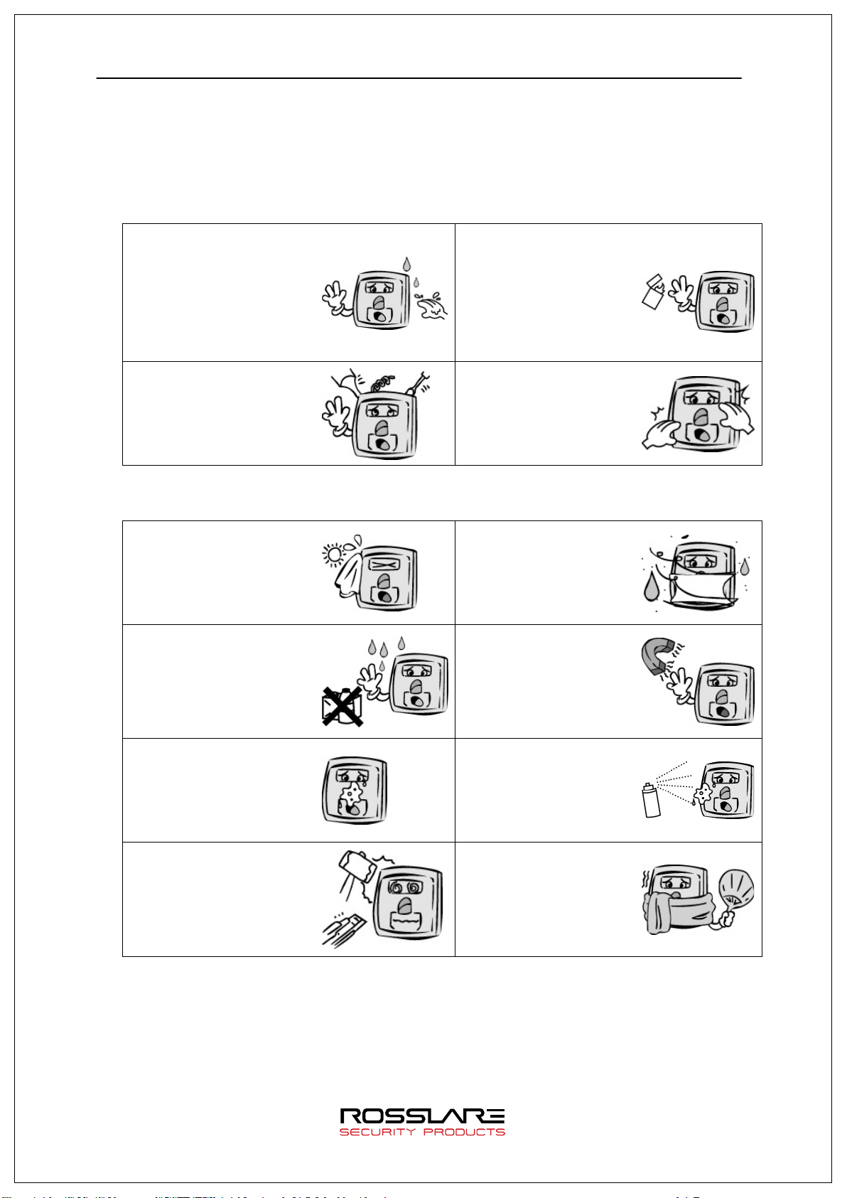
1.1. Safety Notes
Warning
Do not operate the terminal
with wet hands, and pay
Keep the terminal away
liquid such as water enter
inside the terminal.
- > Otherwise, malfunction
or electric shock
caused.
Do not disassemble, repair
or remodel the terminal at
your disposal.
- > Otherwise, it may cause
malfunction, electric shock,
or a fire.
from inflammables.
- >
cause a fire.
Do not allow children to
carelessly.
- >
cause safety accidents of
children or malfunction.
- Non-compliance of safety notes may cause death or serious injury for users.
Cautions
Do not install the terminal
in a place exposed to direct
sunlight.
→ Otherwise, it may cause
and discoloration.
Do not clean this terminal
by sprinkling water, nor
wipe it with benzene,
thinner, and alcohol.
→ Otherwise, it may cause
electric shock or a fire.
Keep the fingerprint input
section clean.
→
fingerprint cannot be
recognized correctly.
Keep the terminal away
from shock or sharp
objects.
→
result in malfunction.
Do not install the terminal
in humid or dusty places.
→
cause malfunction.
Keep the terminal away
from magnets.
→
malfunction.
Do not spray insecticides
or inflammables on the
terminal.
→
discoloration.
Do not install the terminal
in a place where there is
a severe change in
temperature.
→
cause malfunction.
- Non-compliance of safety notes may cause personal injury or property damage for
users.
* We are not responsible for any accidents and damage that may arise from non-
compliance of the information in this manual.
1.2. Product Details
Page 6
AY-B9250BT User Guide 6
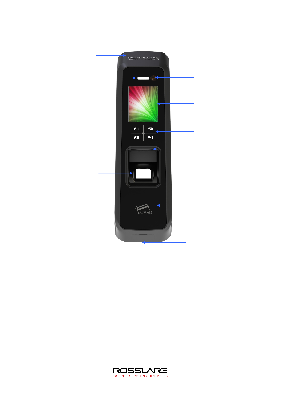
Camera
LCD
Speaker
Card Sensor (EM/SC/HID)
Fingerprint
State LED
USB assist device
1.2.1. FRONT
BLE embedded
Function KEY (F1~F4)
Sensor
(UDL10) connection
Page 7
AY-B9250BT User Guide 7
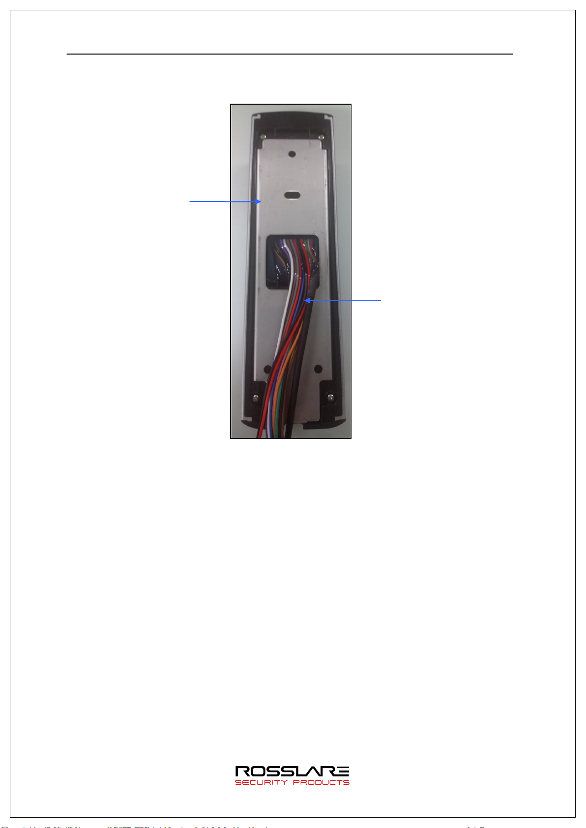
Fixed bracket
1.2.2. REAR
Cable harness
Page 8
AY-B9250BT User Guide 8
5
BLACK
GND
GND
-
Ground connection(for
7
BLACK
PGND
Power GND
-
Power supply ground
8
GREEN
R4A
RS485A
BI
RS-485 interface
10
ORANGE
WO0
WIE_OUT0
OUT
Output WIGAND (WO0)
12
BROWN
WI0
WIE_IN0
IN
Input WIGAND (WI0)
15
RED
-
N_TXN
OUT
LAN I/F (LAN cable)
17
GREEN
-
N_RXN
IN
LAN I/F (LAN cable)
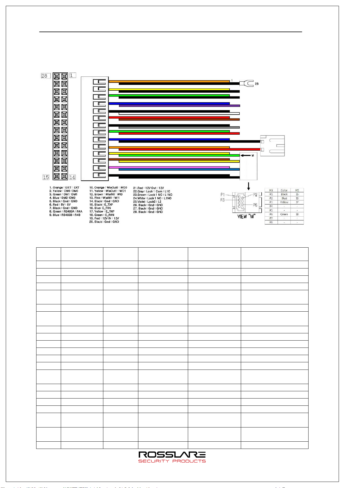
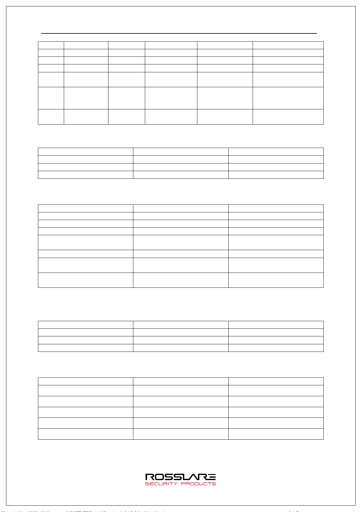
1.2.3. Input / Output
Cable & Connector 1.2.3.1.
Pin
number
1
2
3
4
6
9
11
13
14
Pin Details 1.2.3.2.
Line color Label
(Line name)
ORANGE
YELLOW
GREEN
BLUE
RED
BLUE
YELLOW
PURPLE
BLACK
EXT Inside open IN Connect to Exit button
DM0 DoorMonitor0 IN Sense door state(DM0)
DM1 DoorMonitor1 IN Sense door state(DM1)
DM2 DoorMonitor2 IN Sense door state(DM2)
5V DC5V OUT DC 5V output
R4B RS485B BI RS-485 interface
WO1 WIE_OUT1 OUT
WI1 WIE_IN1 IN
GND GND - Ground connection
Explanation IN/OUT Note
door monitor)
connection
Output WIGAND (WO1)
Input WIGAND (WI1)
(WIGAND signal)
16
18
19
20
21
BLACK
WHITE
RED
BLACK
RED
- N_TXP OUT LAN I/F (LAN cable)
- N_RXP IN LAN I/F (LAN cable)
12V DC12V IN DC 12V power supply
input
GND Power GND - Power supply ground
connection (Adapter)
12V DC12V OUT DC 12V put out power
Page 9
AY-B9250BT User Guide 9
23
BROWN
L1NC
LOCK1_NC
OUT
Lock1 NC terminal
(Lock connecter)
28
PGND
Panel GND
-
Panel ground
RS485A
R4A (green)
RDRA+
RS485B
R4B (blue)
485B
DOOR MONITOR
IN1 (If this pin is not used,
Lock
L1NC (Green)
+
22
24
25
26
27
GRAY
WHITE
PURPLE
BLACK
BLACK
BLACK
L1C LOCK1_COM OUT Lock1 COM terminal
L1NO LOCK1_NO OUT Lock1 NO terminal
L2 LOCK2 OUT Lock2 terminal
GND GND - Ground connection
PGND Power GND - Power supply ground
connection (Lock
power)
connection (Earth)
Terminal <- > MCP040 wiring 1.2.3.3.
Category T2 terminal (Line name) MCP040
RS485B R4B (blue) RDRA-
ground connection GND (black) G
Terminal <- > LC015B wiring 1.2.3.4.
Category T2 terminal (Line name) LC015B
RS485A R4A (green) 485A
ground connection GND (black) GND
connect to GND pin.)
INSIDE OPEN IN0
DC12V (LC015B separate power
supply)
ground connection (Power only
for LC015B)
But, door open time can be set with DIP SWITCH of LC015B (Maximum open time is 5 sec.)
DC12V IN
GND
Terminal <- > EM Type Door Lock wiring 1.2.3.5.
Category T2 terminal (Line name) EM Door Lock
GND GND (Black) -
Door Monitor DM0 (Black) NC(Normal Close)
Terminal <- > WIEGAND Device wiring 1.2.3.6.
Category T2 terminal (Line name) WIEGAND Device
WIEGAND INPUT0 WI0 Wiegand output0
WIEGAND INPUT1 WI1 Wiegand output1
WIEGAND OUTPUT0 WO0 Wiegand input0
WIEGAND OUTPUT1 WO1 Wiegand input1
1.3. Screen information during operation
GND GND GND
Page 10
AY-B9250BT User Guide 10
NONE
: Normal
RIGHT
F4
Move cursor to right
ENTER
F4 long or
Move to submenu
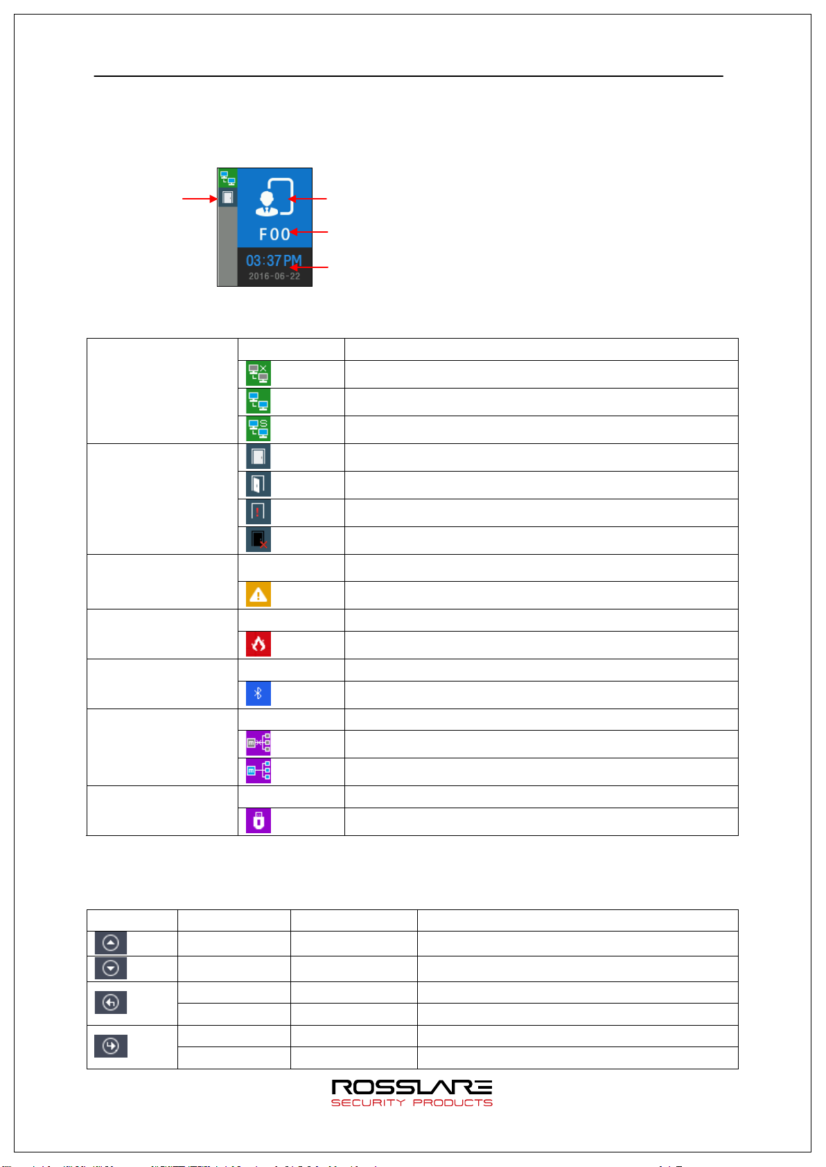
State icon
Operation Mode
1.3.1. Initial Screen
When powering on at first, the screen is displayed as follow.
TNA Mode
Date and Time
1.3.2. Icons
NONE : No use network
Server connection
State
: LAN line is disconnected.
: LAN line is connected (only link is connected)
: Connected with server
: Gate is closed.
: Gate is opened
: Gate is opened forcedly (unusual door open state)
: Gate communication problem
: Terminal Disassembly State
Gate
State
Warning signal
State
NONE : Normal
Fire detection
State
BLE connection
State
NONE : Disconnected with Admin App
: Sensed by fire detector (valid on DM2 fire set)
: Connected with Admin App
NONE : MCP040 is not used (Normal state)
MCP040 connection
State
UDL connection
State
NONE : UDL is not used (Normal state)
: MCP040 Mode and bad communication state
: MCP040 Mode and normal communication state
: UDL is connected
1.3.3. Function KEY
Icon Meaning Function Key Explanation
UP F1 Move cursor up
DOWN F3 Move cursor down
LEFT F2 Move cursor to left
ESC F2 long Move to upper menu
Page 11
AY-B9250BT User Guide 11
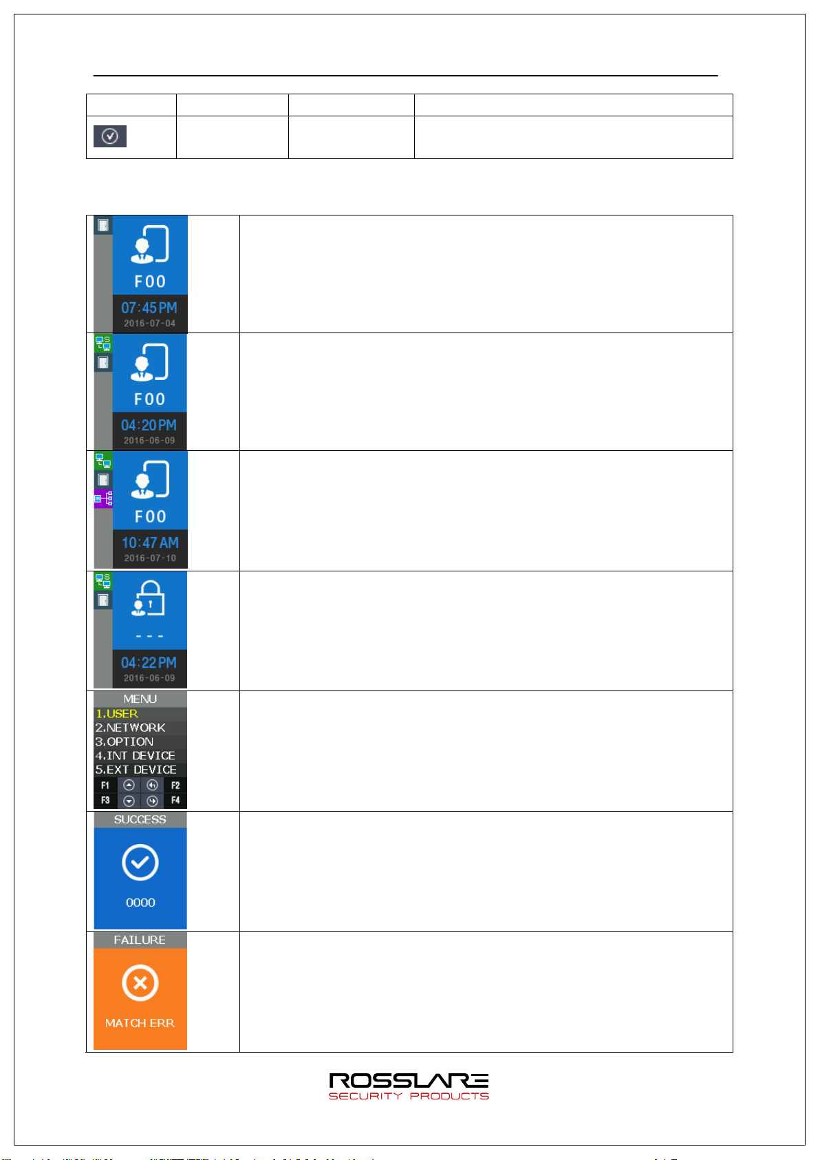
ENABLE
F4
DISABLE
1.3.4. Main Screen
F2 Category choice (ENABLE or DISABLE)
Operating in Exclusive mode
Initial Screen
Operating in Network mode
Initial Screen
Operating in Dummy mode
Initial Screen
Operating in lock mode
(Reject all users authentication)
Menu of Initial Screen
Authentication success
Authentication failure
Page 12
AY-B9250BT User Guide 12
ON (Maintain during authentication time)
Normal
OFF
LOCK OPEN
ON
BLUE
Terminal Normal(alive)
Flash at intervals of 5 seconds
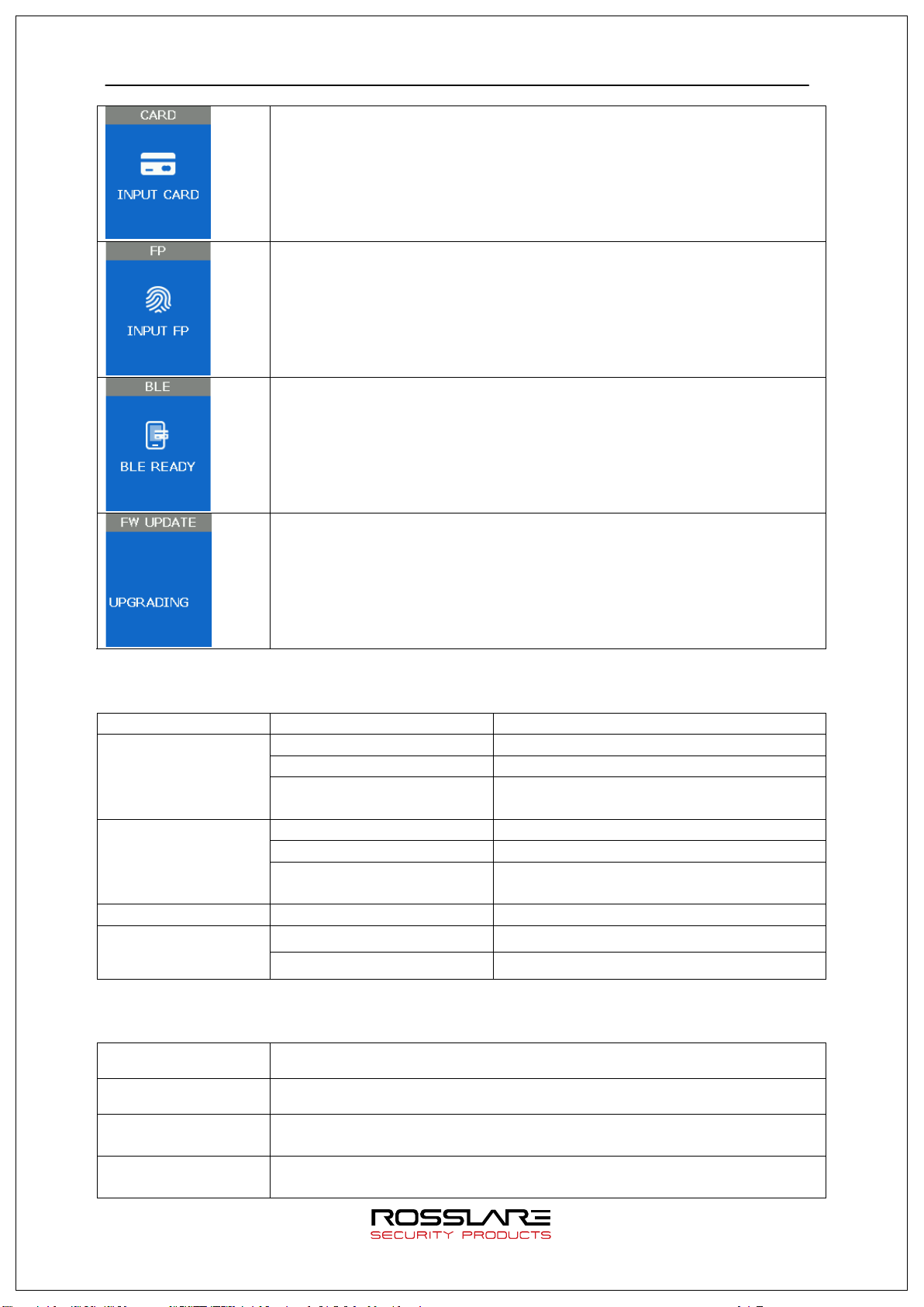
Waiting for Card Input
Waiting for Fingerprint Input
Waiting for Admin App registration
Upgrading firmware
1.4. LED information during operation
LED Operating state Remark
Normal OFF
RED
Alarm ON or Flash
Authentication Failure
GREEN
Authentication Success
Function Key
LED
Enter menu Always ON
Touch in initial screen. ON(Maintain for 10 seconds) OFF
1.5. Voice information during operation
OFF
ON (Maintain during authentication time)
OFF
Category Voice information
Fingerprint Input Please enter your fingerprint.
Authentication
success
Authentication
failure
You are authorized.
Please try again.
Page 13
AY-B9250BT User Guide 13
inputting fingerprint, input has
It shows the state for waiting user’s input
Authentication success or setting
1.6. Buzzer guide announced during operation
Buzzer Sound State Explanation
Key touch
Beep
Card tag
Fingerprint touch
2 Beeps Failure
Long Beep Waiting for input
Short Beeps Success
-Pressing key or reading card
-When
been completed and hands can take off.
If authentication fails or the user's input is
wrong
such as fingerprint or password.
completion
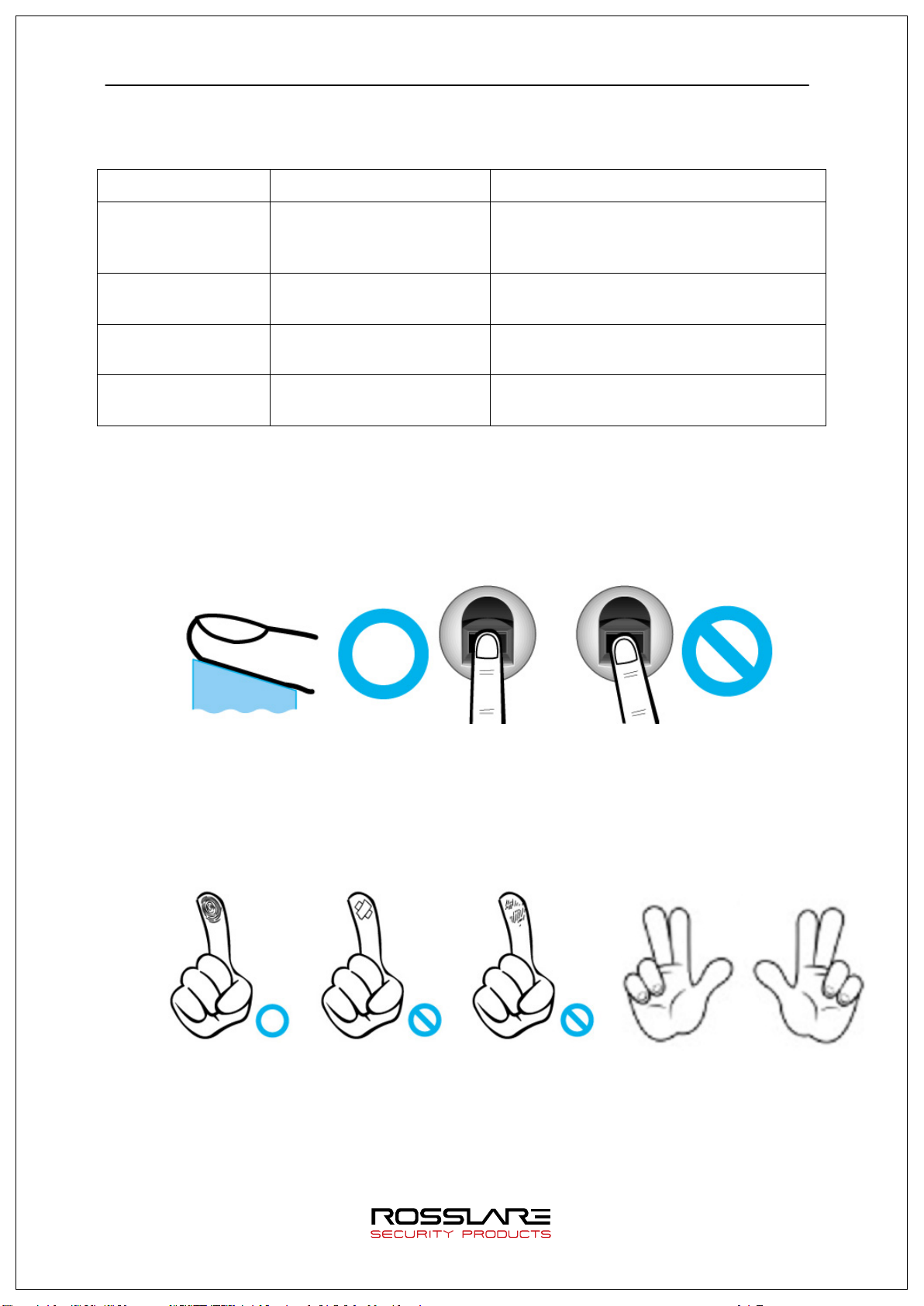
1.7. How to register and enter the correct fingerprint
Correct fingerprint input method
Enter your fingerprint as if you take a thumbprint by using your forefinger if possible.
The fingerprint cannot be correctly registered and entered only by your fingertips.
The center of the fingerprint should be touched with the fingerprint input section.
Enter the fingerprint of your forefinger if possible.
When using your forefinger, you can enter your fingerprint correctly and safely.
Make sure that the fingerprint is unclear or wounded.
Too dry, wet, blurry or wounded fingerprints are difficult to recognize. In this case,
the fingerprint of another finger should be registered.
Precautions subject to your fingerprint state.
The availability of the fingerprint may vary subject to your fingerprint state.
This product consists of a fingerprint recognition system and cannot recognize
the damaged or unclear fingerprints. The fingerprint should be registered using
the RF card.
Page 14

AY-B9250BT User Guide 14
Fingerprint
Fingerprint registration
Card
Card, Fingerprint registration
Mobile card
Mobile Card registration (registration only via server and admin
Mobile Card authentication
If your hands are dry, you can blow your breath on the system to operate
it more smoothly.
For children, too small or unclear fingerprints may be difficult or impossible to use.
They need to register a new fingerprint every six months.
For seniors, the fingerprint with too many lines may not be registered.
It is recommended that you register more than two fingerprints if possible.
In order to increase the fingerprint authentication rate, it is recommended to use
six of the ten fingers as illustrated below (both thumbs, forefingers, middle
fingers).
2. Product Description
2.1. Product Features
BLE is equipped. Door Control with smartphone is possible at close range.
It is equipped with Color Camera, and it saves the visitor’s video when authentication
succeeds or fails.
Optional, Available to use as RF(125kHz), Smart Card(13.56MHz), HID Reader
Easy to verify your ID via fingerprint
- The use of the fingerprint recognition technology (Biometrics) can prevent
forgetting your password, losing your card or key, or avoid the risk of their theft.
The use of personal fingerprints enhances the security of authentication.
Access control system using the local area network (LAN)
- The fingerprint reader communicates with the authentication server using a TCP/IP
protocol. Therefore, this terminal can be applied to the existing LAN and has easy
expandability. It ensures a fast speed by 10/100 Mbps Auto Detect and
facilitates management and monitoring via the network.
Provide various registration and authentication method
Fingerprint authentication
Card Card registration
Card
or Fingerprint
and Fingerprint
Card authentication
Card, Fingerprint registration
Card or Fingerprint authentication
Fingerprint authentication after Card authentication
App)
Page 15
AY-B9250BT User Guide 15
BLE 2.4G
Open
Mobile App
RS485
Ethernet
Server
Lock/Open
Lock/Open
Lock/Open
#2
#1
#3
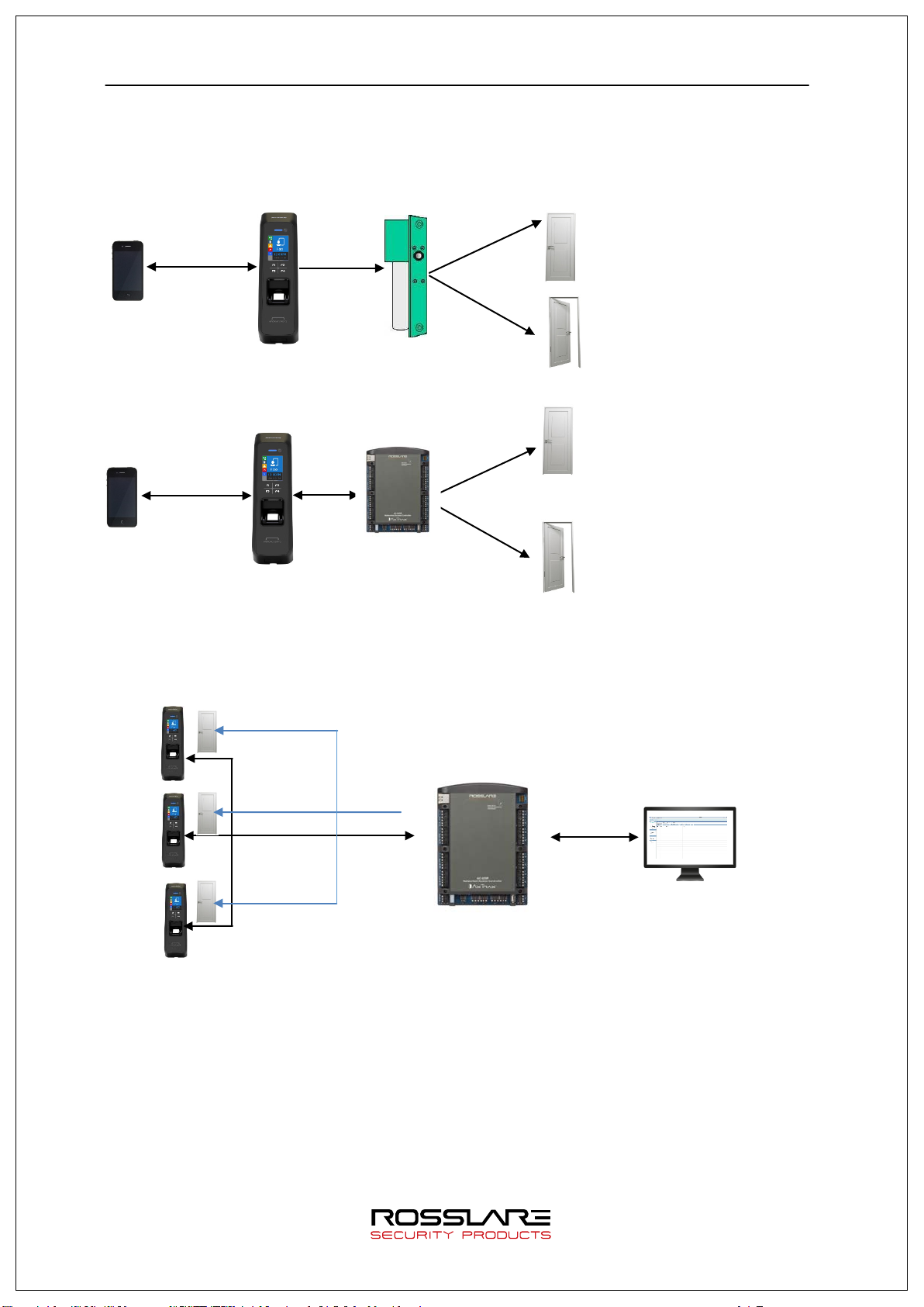
2.2. Diagram
2.2.1. Single Type (Door Lock)
Mobile App
Lock
control
T2
2.2.2. Single Type (Lock Controller)
BLE 2.4G
T2
Lock
Controller
2.2.3. Dummy Type
RS485ID
RS485ID
RS485ID
AY-B9250BT
RS485
Door Lock
Close
Close
Open
Page 16
AY-B9250BT User Guide 16
BLE 2.4G
Mobile App
Ethernet
Ethernet
Internet
BLE 2.4G
Mobile App
Ethernet
Open
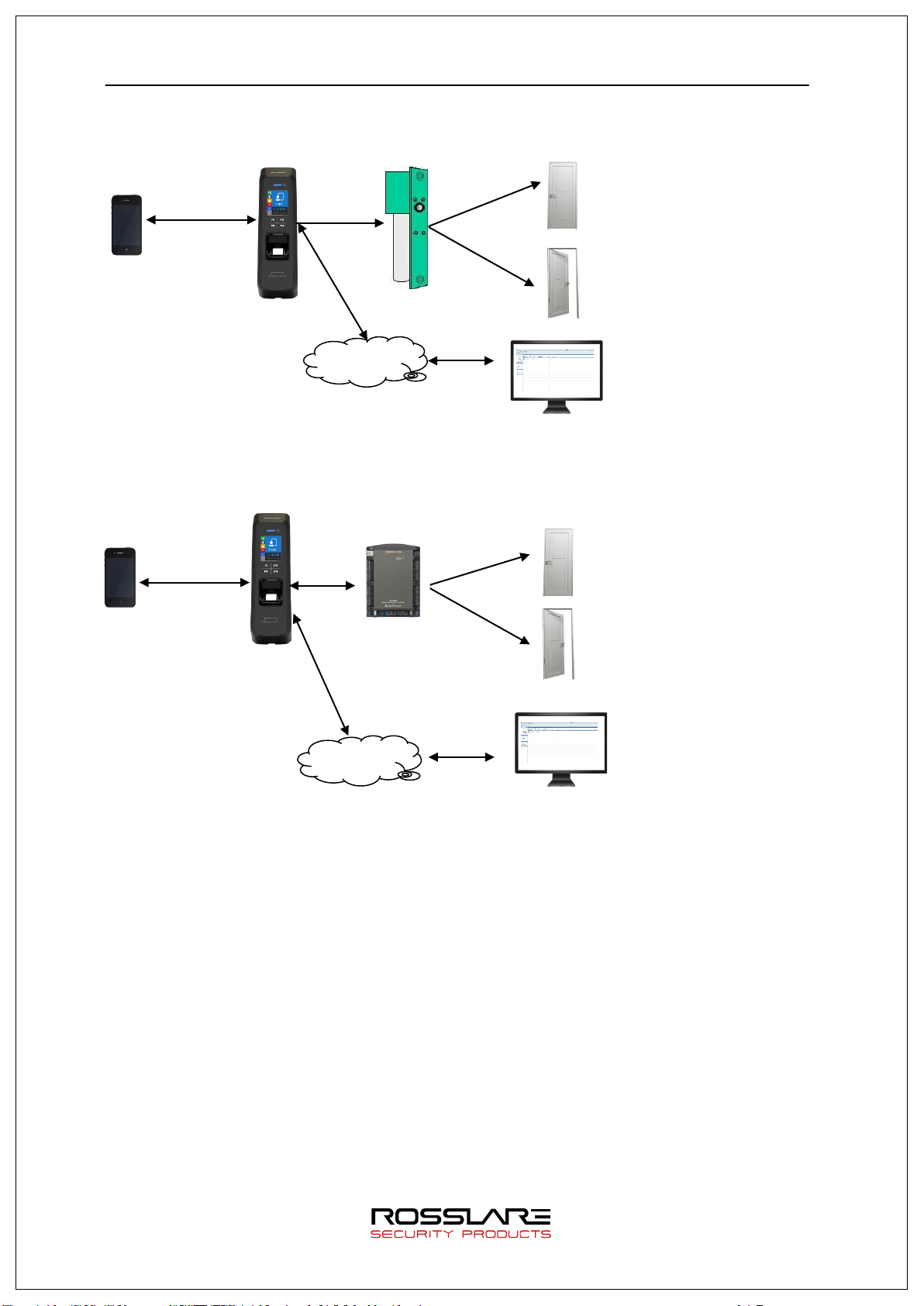
2.2.4. Network Type (Door Lock)
T2
Lock
Control
Door Lock
Close
Open
Server
2.2.5. Network Type (Lock Controller)
T2
RS485
Close
Lock Controller
Ethernet
Internet
Server
Page 17
AY-B9250BT User Guide 17
CPU
32Bit RISC CPU(400MHz)
MEMORY
64M DDR RAM, 32M NOR,128M NAND
Camera
VGA, F2.8, View angle 61 degree
LCD
1.77’’ Color LCD
Fingerprint Sensor
Optical / 500 DPI
20,000 Fingerprints, 10,000 users (Two identical fingerprints
fingerprints is less than 200.
Lock
Deadbolt, EM Lock, Door Strike, Automatic Door
Certification
KC, CE, FCC
Size
58mm(W) * 191mm(H) * 62mm(D)
2.3. Product Specification
Category Spec
Authentication Method Fingerprint, RF Card, Mobile Card
Authentication Speed 1:N < within 1 sec. (based on 1,000 fingerprints)
Fingerprint capacity
registration per user)
Note) Similar fingerprint inspection is possible when the number of
Log capacity 100,000 logs
Communication interface TCP/IP, Wiegand In/Out (26/34bit),RS485
Temperature /
Humidity
-20~60 ℃ / < RH 90%
Page 18
AY-B9250BT User Guide 18
3. Environment Setting
3.1. Checkpoints before Environment Setting
3.1.1. Menu
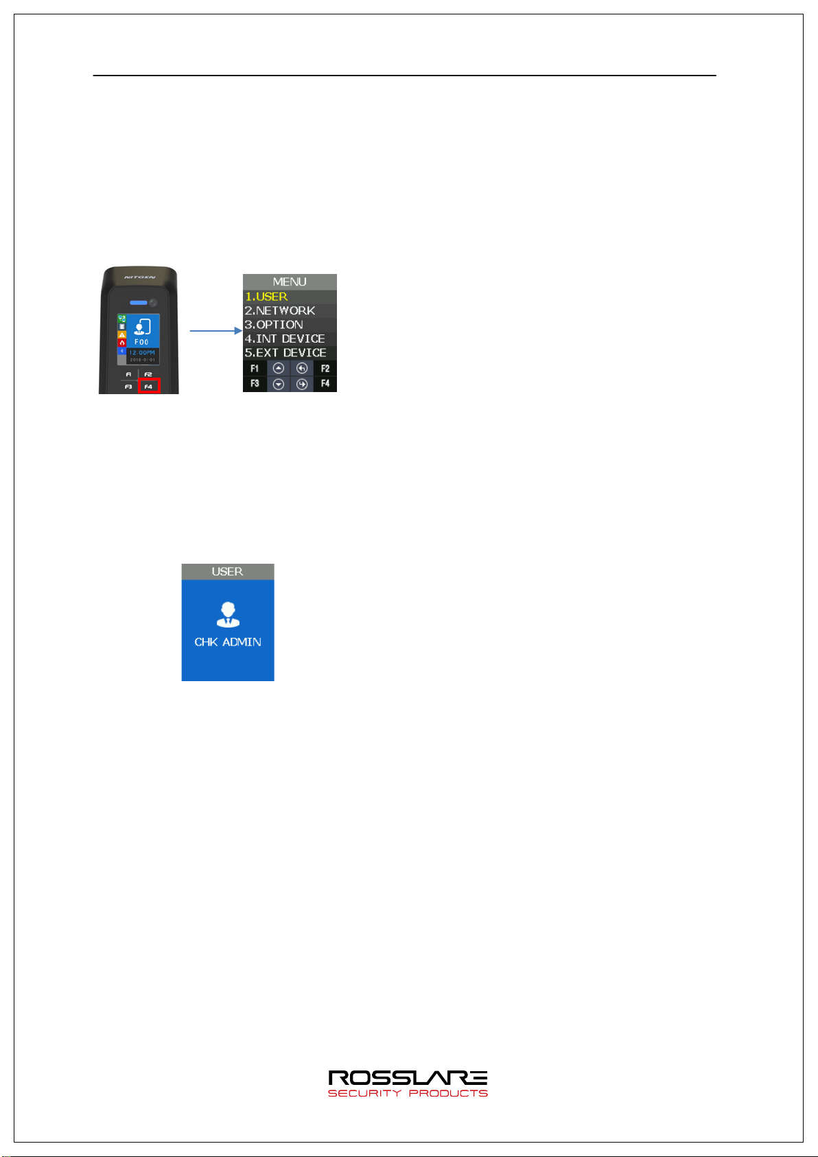
Press F4 long until the menu screen is displayed.
It is available to enter the menu without authentication because the manager doesn’t register
when shipping the product.
3.1.2. Administration authentication
When the administrator is registered, the admin authentication screen is displayed at first as
follows.
▶ Administrator authentication
Administrator authentication is progressed with
fingerprint and card. You can access each menu if the
authentication succeeds.
Admin authentication is displayed only if there is a
registered user. Admin authentication displays only if
admin is enrolled already. The admin authentication is
needed only in accessing menu mode. It enables to
access every menu until you completely escape from
main menu.
Page 19
AY-B9250BT User Guide 19
OFF
ON
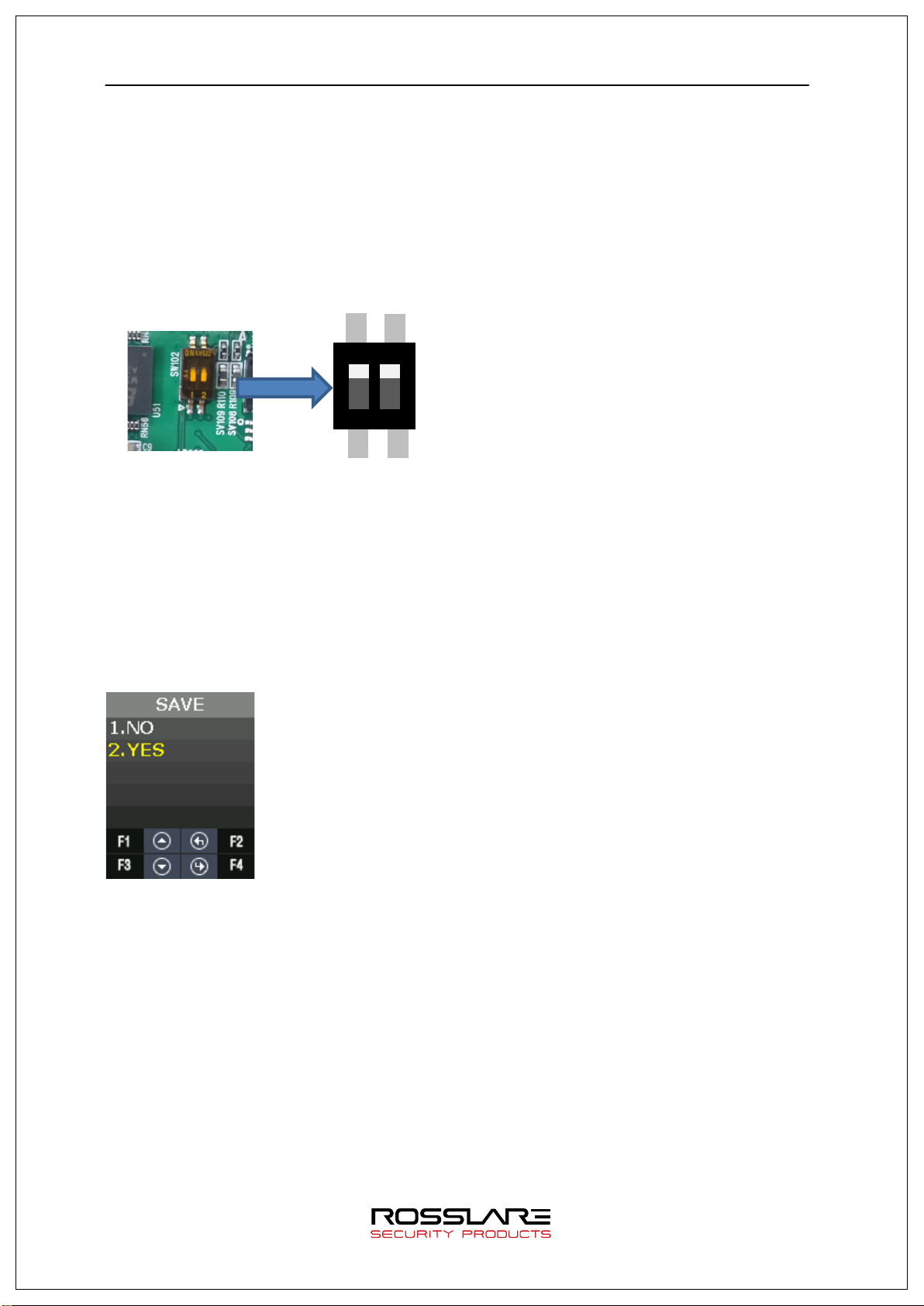
3.1.3. How to access the menu without administrator authentication
This is the method to enter the Menu in exceptional cases such as losing your administrator
card that is registered in the terminal or inability to make a fingerprint authentication because
of absence of administrator.
① Power terminal OFF.
② Disassemble device and make case open state.
③ While case opens, make DIP of rear side switch ON state as follows.
ON
1
2
④ Power terminal ON.
⑤ After the terminal completely booted, Press F1 longer to enter the menu with buzzer
sound “Ppiririk”.
★ Caution: You should return DIP SWITCH OFF after modification.
3.1.4. Save Settings
▶ If there are some changes, the following screen appears.
▶ If you select “YES”, then save them with buzzer sound “Ppibibig” and reboot.
▶ If there are no changes, it returns to the previous menu screen.
▶ While changing the settings in the menu, if there is no input for 30 seconds, it returns to
the previous menu.
Page 20

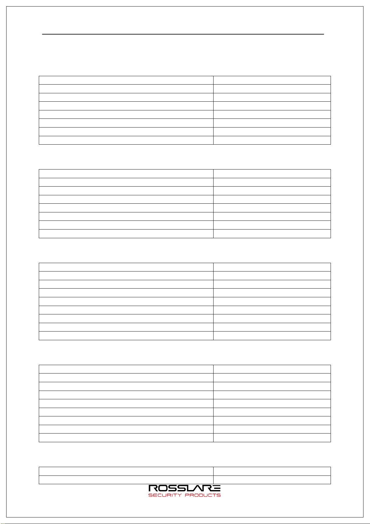
AY-B9250BT User Guide 20
Category
Default setting
MENU > NETWORK > USE > TERMINAL ID
1
MENU > NETWORK > USE > TERMINAL >
STATIC
MENU > NETWORK > USE > SERVER
IP:192.168.0.2
MENU > OPTION > ATTEND > TYPE
F1~F4
MENU > OPTION > ATTEND > AUTO TNA
NO
MENU > OPTION > SCREEN > USER LOGO
NO
MENU > OPTION > SCREEN > USER ID LEN
4
MENU > OPTION > SCREEN > DATE > FORMAT
YYMMDD
MENU > OPTION > TIME OUT > RESULT
1sec
MENU > OPTION > TIME OUT > NET ERROR
30sec
MENU > OPTION > LOCKING
NO USE
MENU > INT DEVICE > FP SENSOR > 1:N LEVEL
8
MENU > INT DEVICE > FP SENSOR > LFD LEVEL
NONE
MENU > INT DEVICE > VOICE
3
MENU > INT DEVICE > TAMPER
Alarm
MENU > EXT DEVICE > DOORLOCK > LOCK1 > OPEN
MENU > EXT DEVICE > DOORLOCK > LOCK2 > OPEN
MENU > EXT DEVICE > DOORLOCK > DM0
NONE
MENU > EXT DEVICE > DOORLOCK > DM1
NONE
MENU > EXT DEVICE > WIEGAND > WIRE-INPUT
NONE
MENU > EXT DEVICE > WIEGAND > WIRE-OUTPUT
NONE
3.1.5. Default Setting
MENU > NETWORK USE
MENU > NETWORK > USE > AUTH MODE TN
MENU > NETWORK > USE > TERMINAL > STATIC > IP:192.168.0.3
SN:255.255.255.0
GW:192.168.0.1
PORT: 7332
MENU > OPTION > SCREEN > LANGUAGE English
MENU > OPTION > SCREEN > SHOW ID YES
MENU > OPTION > SAVE > LOG SAVE Yes
MENU > OPTION > SAVE > IMAGE SAVE No
MENU > OPTION > TIME OUT > PING 60sec
MENU > INT DEVICE > FP SENSOR > 1:1 LEVEL 5
MENU > INT DEVICE > FP SENSOR > AUTH TIME 5sec
MENU > INT DEVICE > BEEP 3
MENU > EXT DEVICE > DOORLOCK > LOCK1 > TYPE STRIKE/OK
3sec
TIME
MENU > EXT DEVICE > DOORLOCK > LOCK2 > TYPE None
3sec
TIME
MENU > EXT DEVICE > DOORLOCK > OPEN ALARM 5sec
MENU > EXT DEVICE > DOORLOCK > DM2 NONE
MENU > EXT DEVICE > RS485 > TYPE NONE
MENU > EXT DEVICE > RS485 > DEV ID 0
MENU > EXT DEVICE > WIEGAND > WIRE-OUTPUT>
26 BIT or 34 BIT > SITE CODE
MENU > EXT DEVICE > WIEGAND > WIRE-OUTPUT>
26 BIT or 34 BIT > SITE CODE > SEND INFO
0
UID
Page 21
AY-B9250BT User Guide 21
Menu position
Possible setting
MENU>NETWORK>
NO USE
MENU>EXT DEVICE>DOORLOCK>DM0
N/O or N/C
MENU>EXT DEVICE>DOORLOCK>DM1
NONE
MENU>EXT DEVICE>DOORLOCK>DM2
NONE
Menu position
Possible setting
MENU>EXT DEVICE>DOORLOCK>LOCK1>TYPE
MOTOR1
MENU>EXT DEVICE>DOORLOCK>DM2
NONE
MENU>EXT DEVICE>RS485>TYPE
NONE
MENU>EXT DEVICE>DOORLOCK>DM0
NONE
MENU>EXT DEVICE>DOORLOCK>LOCK2>TYPE
NONE
MENU>EXT DEVICE>RS485>TYPE
LC010
MENU>EXT DEVICE>RS485>DEV ID
0
Menu Position
Possible setting
MENU>EXT DEVICE>DOORLOCK>DM0
NONE
MENU>EXT DEVICE>DOORLOCK>LOCK2>TYPE
NONE
MENU>EXT DEVICE>RS485>TYPE
LC015
MENU>EXT DEVICE>RS485>DEV ID
0
Menu Position
Possible setting
3.1.6. Setting guide for Network Configuration
Single Type (Door Lock=STRIKE) 3.1.6.1.
MENU>EXT DEVICE>DOORLOCK>LOCK1>TYPE STRIKE/OK
MENU>EXT DEVICE>DOORLOCK>LOCK2>TYPE NONE
MENU>EXT DEVICE>RS485>TYPE NONE
Single Type (Door Lock=MOTOR) 3.1.6.2.
MENU>NETWORK> NO USE
MENU>EXT DEVICE>DOORLOCK>DM0 N/O or N/C
MENU>EXT DEVICE>DOORLOCK>LOCK2>TYPE MOTOR2
MENU>EXT DEVICE>DOORLOCK>DM1 N/O or N/C
Single Type (Lock Controller=LC010) 3.1.6.3.
Menu position Possible setting
MENU>NETWORK> NO USE
MENU>EXT DEVICE>DOORLOCK>LOCK1>TYPE NONE
MENU>EXT DEVICE>DOORLOCK>DM1 NONE
MENU>EXT DEVICE>DOORLOCK>DM2 NONE
Single Type (Lock Controller=LC015) 3.1.6.4.
MENU>NETWORK> NO USE
MENU>EXT DEVICE>DOORLOCK>LOCK1>TYPE NONE
MENU>EXT DEVICE>DOORLOCK>DM1 NONE
MENU>EXT DEVICE>DOORLOCK>DM2 NONE
Dummy Type (RS485=MCP040) 3.1.6.5.
MENU>NETWORK> N/A
Page 22

AY-B9250BT User Guide 22
MENU>EXT DEVICE>DOORLOCK>LOCK1>TYPE
NONE
MENU>EXT DEVICE>DOORLOCK>DM0
NONE
MENU>EXT DEVICE>DOORLOCK>LOCK2>TYPE
NONE
MENU>EXT DEVICE>DOORLOCK>DM2
NONE
MENU>EXT DEVICE>RS485>TYPE
MCP040
MENU>EXT DEVICE>RS485>DEV ID
Use in 1~7
MENU>NETWORK>USE>AUTH MODE
TN
MENU>NETWORK>USE>TERMINAL ID
0001
MENU>NETWORK>USE>TERMINAL>STATIC
IP:192.168.0.3
MENU>NETWORK>USE>SERVER
IP:192.168.0.2
MENU>EXT DEVICE>DOORLOCK>LOCK1>TYPE
STRIKE/OK
MENU>EXT DEVICE>DOORLOCK>DM0
N/O or N/C
MENU>EXT DEVICE>DOORLOCK>DM1
NONE
MENU>EXT DEVICE>RS485>TYPE
NONE
Menu Position
Possible setting
MENU>NETWORK>USE>AUTH MODE
TN
MENU>NETWORK>USE>TERMINAL>STATIC
IP:192.168.0.3
MENU>EXT DEVICE>DOORLOCK>DM0
N/O or N/C
MENU>EXT DEVICE>DOORLOCK>LOCK2>TYPE
MOTOR2
Menu Position
Possible setting
MENU>NETWORK>USE>TERMINAL ID
0001
MENU>NETWORK>USE>TERMINAL>STATIC
IP:192.168.0.3
(Use : When only downloading DB)
MENU>EXT DEVICE>DOORLOCK>DM1 NONE
Network Type (Door Lock=STRIKE) 3.1.6.6.
Menu Position Possible setting
MENU>NETWORK> USE
SN:255.255.255.0
GW:192.168.0.1
PORT:7332
MENU>EXT DEVICE>DOORLOCK>LOCK2>TYPE NONE
MENU>EXT DEVICE>DOORLOCK>DM2 NONE
Network Type (Door Lock=MOTOR) 3.1.6.7.
MENU>NETWORK> USE
MENU>NETWORK>USE>TERMINAL ID 0001
SN:255.255.255.0
GW:192.168.0.1
MENU>NETWORK>USE>SERVER IP:192.168.0.2
PORT:7332
MENU>EXT DEVICE>DOORLOCK>LOCK1>TYPE MOTOR1
MENU>EXT DEVICE>DOORLOCK>DM1 N/O or N/C
MENU>EXT DEVICE>DOORLOCK>DM2 NONE
MENU>EXT DEVICE>RS485>TYPE NONE
Network Type (Lock Controller=LC010) 3.1.6.8.
MENU>NETWORK> Use
MENU>NETWORK>USE>AUTH MODE TN
SN:255.255.255.0
Page 23

AY-B9250BT User Guide 23
MENU>NETWORK>USE>SERVER
IP:192.168.0.2
PORT:7332
MENU>EXT DEVICE>DOORLOCK>DM0
NONE
MENU>EXT DEVICE>DOORLOCK>LOCK2>TYPE
NONE
MENU>EXT DEVICE>RS485>TYPE
LC010
MENU>EXT DEVICE>RS485>DEV ID
0
MENU>NETWORK>USE>TERMINAL ID
0001
MENU>NETWORK>USE>TERMINAL>STATIC
IP:192.168.0.3
MENU>NETWORK>USE>SERVER
IP:192.168.0.2
MENU>EXT DEVICE>DOORLOCK>LOCK1>TYPE
NONE
MENU>EXT DEVICE>DOORLOCK>DM0
NONE
MENU>EXT DEVICE>RS485>TYPE
LC015
MENU>EXT DEVICE>RS485>DEV ID
0
GW:192.168.0.1
MENU>EXT DEVICE>DOORLOCK>LOCK1>TYPE NONE
MENU>EXT DEVICE>DOORLOCK>DM1 NONE
MENU>EXT DEVICE>DOORLOCK>DM2 NONE
Network Type (Lock Controller=LC015) 3.1.6.9.
Menu Position Possible setting
MENU>NETWORK> USE
MENU>NETWORK>USE>AUTH MODE TN
SN:255.255.255.0
GW:192.168.0.1
PORT:7332
MENU>EXT DEVICE>DOORLOCK>LOCK2>TYPE NONE
MENU>EXT DEVICE>DOORLOCK>DM1 NONE
MENU>EXT DEVICE>DOORLOCK>DM2 NONE
3.2. Access and Registration between Rosslare Bio9000 and terminal
3.2.1. Install Rosslare Bio9000
When shipping the product, it comes with a CD to install Rosslare Bio9000 on your PC.
For installation guide, please refer to the relevant document.
3.2.2. Execute Rosslare Bio9000
If executing the program, login screen is displayed.
Enter User ID that is previously registered and password and then press OK.
Page 24

AY-B9250BT User Guide 24
If login is successful, the screen is displayed as follows.
3.2.3. Set in terminal
In order to connect the terminal to the server, set to the network mode and set the
information.
Move to MENU > NETWORK > USE > TERMINAL and check whether lower information is
correct or not. If you have not changed the device network information, it is displayed as
follows.
Page 25
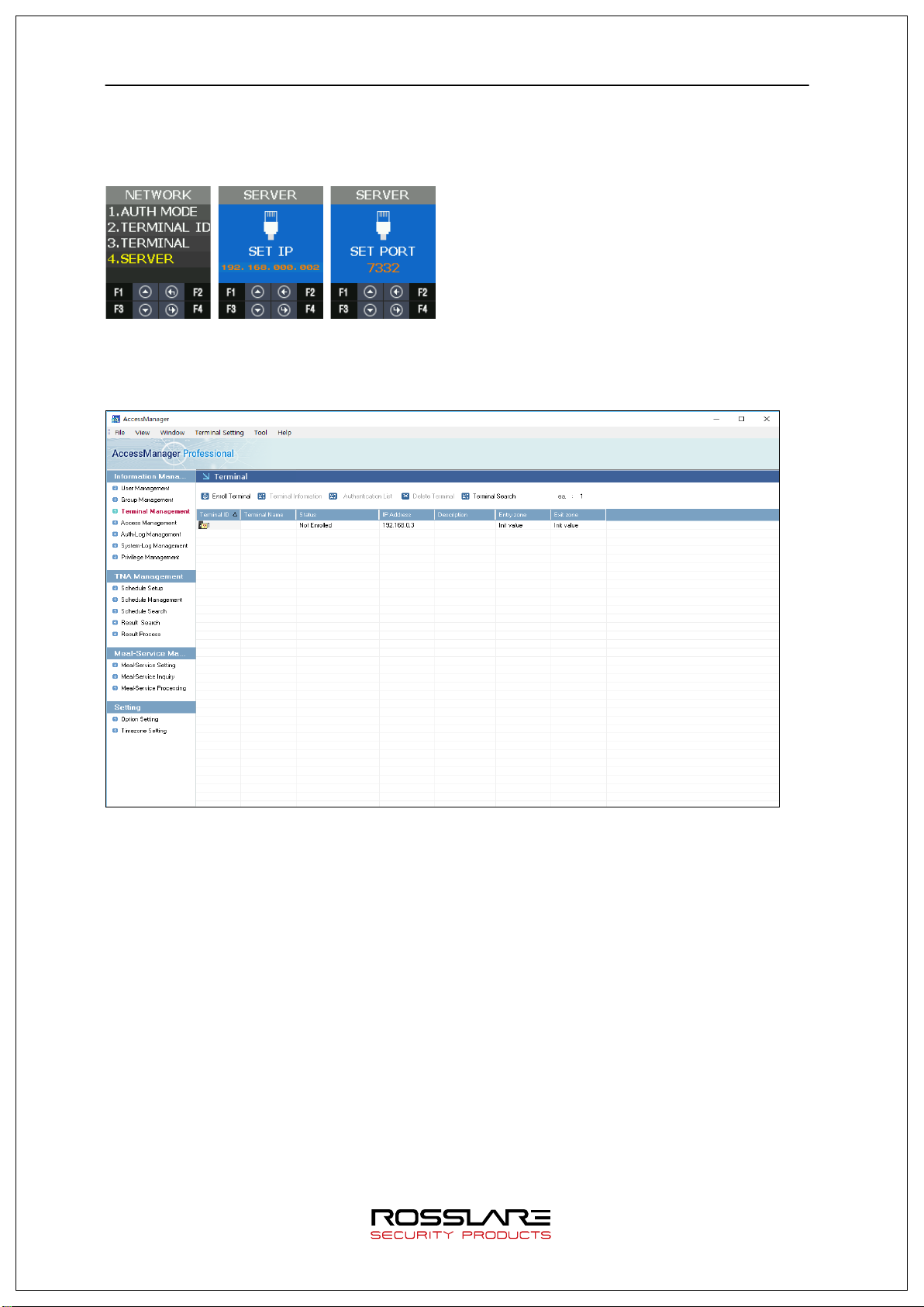
AY-B9250BT User Guide 25
In order to access the server
Move to MENU > NETWORK > USE > SERVER and check the lower information correctly
sets or not. If you do not change the server network information, it is displayed as follows.
3.2.4. LAN connection in terminal
At first, you can see the unregistered state because the terminal is not registered.
3.2.5. Register the terminal in Rosslare Bio9000
Select the unregistered terminal and press Registration button to activate the screen below.
Enter device name and explanation to press OK.
Page 26

AY-B9250BT User Guide 26
If the registration is successful, the screen is displayed as follow.
For more details about Rosslare Bio9000 operation, please refer to the guide document.
Page 27

USER
ADD
USER
USER
INPUT ID
*Authentication Type
MCARD is not admitted to set up,
Card
UID > Card > OK
MODIFY
INPUT ID
MCARD is not admitted to set up,
NETWORK
NO USE
Operate in single mode
USE
AUTH MODE
Server/Terminal
AY-B9250BT User Guide 27
3.3. Menu Configuration
The whole menu is composed of seven, and main characteristics are as follows.
Menu Submenu1 Submenu2 Submenu3
ADMIN
Card
FP
MCARD
*Authentication Condition
OR
AND
※ MCARD is OR condition only.
※
state check only.
Password
AUTO ADD FP UID > FP1 > FP2 > OK
*Authentication Type
Card
FP
MCARD
*Authentication Condition
OR
AND
※ MCARD is OR condition only.
※
state check only.
FP registration
(When checking authentication mode)
Card registration
(When checking authentication mode)
DELETE Delete ID
DELETE ALL
Terminal/Server
Server
Terminal
Page 28

STATIC
STATIC
IP
Subnet mask
Gateway
SERVER
SERVER
Port No
OPTION
ATTEND
TYPE
NONE
AUTO TNA
NO
SCREEN
LANGUAGE
SHOW ID
NO
USER LOGO
NO USE
USER ID LEN
4~16
SAVE
LOG SAVE
NO
IMAGE SAVE
NO
TIMEOUT
RESU LT
NET ERROR
Date
FORM
YYMMDD
SETTING
YYYYMMDD-hhmmss
1:1 LEVEL (1~9)
1:N LEVEL (5~9)
LFD LEVEL
NONE
AY-B9250BT User Guide 28
TERMINAL ID TERMINAL ID
DHCP
DHCP
M1 F1~F2
M2 F1~F4
M3 F1~F49
YES
ENGLISH(0)
KOREAN(1)
INDONESIAN(2)
MULTILINGUAL(3)
ARABIC(4)
SPANISH(5)
PORTUGUESE(6)
FRENCH(7)
RUSSIAN(8)
FARSI(9)
JAPANESE(10)
CHINESE(11)
INT
DEVICE
FP SENSOR
PING
YES
USE
YES
YES
DDMMYY
MMDDYY
LOW
MIDDLE
HIGH
Page 29

AY-B9250BT User Guide 29
BEEP
0~3
VOICE
0~5
BLE
BLE READY
LOCK2
* TYPE
OPEN ALARM TIME
5[0~20sec]
DM2
Not use
RS485
TYPE
NONE
DEV ID: 0~255
AUTH TIME
EXT
DEVICE
TAMPER NO ALARM
ALARM
DOOR LOCK LOCK1
DM0
DM1 NONE
*TYPE
Not Use
Strike/OK Indication
Motor1
Schedule alarm
*OPEN TIME
3[1~20sec]
NONE
Fail Indication
Motor2
Schedule alarm
* OPEN TIME
3[1~20sec]
0: No Alarm
1~20: Alarm
NONE
Lock Normal Open
Lock Normal Close
Lock Normal Open
Lock Normal Close
WIEGAND WIRE-INPUT
Normal Open
Normal Close
Fire Normal Open
Fire Normal Close
Panic Normal Open
Panic Normal Close
Urgent Norm Open
Urgent Normal Close
LC010
LC015
SR100
MCP040
*TYPE
NONE
WIE26BIT
WIE34BIT
CUSTOM
Page 30

STATE
DB INFO
USER CN T:
NETWORK
TID: xxxx
OPTION
ATTEND: M2(F1~F4)
INT DEVICE
CARD TYPE: RF/SC
AY-B9250BT User Guide 30
WIRE-OUTPUT *TYPE
NONE
WIE26BIT
WIE34BIT
CUSTOM
*SiteCode
*More Information
UID
CARD
USER MAX:
ADMIN:
FP CN T:
FP MAX:
CARD CNT:
CARD MAX:
M.CD CNT:
LOG CNT:
LOG MAX:
NET: YES, MODE:TN
NET TYPE: STATIC
ENCRYPT: DES
CIP/SN/GW---------
xxx.xxx.xxx.xxx
xxx.xxx.xxx.xxx
xxx.xxx.xxx.xxx
MAC: xx: xx: xx: xx: xx: xx
SIP/PORT---------
xxx.xxx.xxx.xxx
xxxx
AUTO TNA: YES
LANGUAGE: English
SHOW ID: YES
LOGO USE: NO
UID LEN:4
DATE: YYMMDD
LOG SAVE: YES
IMG SAVE:NO
SHOW TO: x
PING TO: x
NET TO: x:
CARD FM T: ST D
FP1:1:x
FP1: N:x
LFD: xx
AUTH TIME:
BEEP VOL:
VOICE VOL:
Page 31

AY-B9250BT User Guide 31
EXT DEVICE
LOCK1----------------------
LOG DB
FACTORY
SELF TEST
INT DEVICE
VOICE
EXT DEVICE
DOORLOCK
BACKUP
LOG EXPORT
USER IMPORT
FW UPDATE
REBOOT
BLE Name/MAC----
XXXXXXX (BLE Name)
XXXXXXXXXXXXXXXXX
TAMPER:ALARM
TYPE: STRIKE/OK
OUT: N/O
OPEN: 3000ms
LOCK2 -------------------
TYPE: NONE
OUT: N/O
OPEN: 3000ms
DOOR WARN: 0sec
FORCE OPEN:NO
RS485: LC010
RS485 ID: xxx
WIEGAND----------------
IN/OUT :34B/34B
SITECODE: xxx
SEND:USERID
I/O PORT LOCK1: HIGH
LOCK2: HIGH
DM0: HIGH
DM1: HIGH
DM2: HIGH
W0IN: HIGH
W1IN: HIGH
INSIDE: HIGH
TAMPER SW:HIGH
VERSION HW
FW
Card
BLE
SN(Serial Number)
RECOVERY INITIALIZE CONFIG
CARD
FP SENSOR
CAMERA
LED
SENSOR IN
USER EXPORT
Page 32

AY-B9250BT User Guide 32
Category
Explanation
ADD
Use to add user and admin with various certification conditions.
MODIFY
DELETE
DELETE ALL
3.4. USER Menu
USER menu has the feature as follows.
AUTO ADD Use to add Card or Fingerprint user automatically.
Use to add certification conditions, card or fingerprint of registered
u se r.
Use to delete a registered particular user.
Use to delete all registered users.
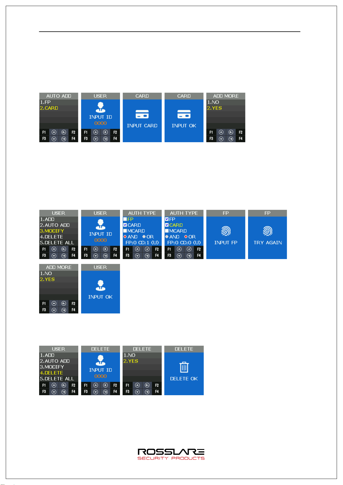
3.4.1. ADD
USER TYPE 3.4.1.1.
If you press ADD in the menu, the screen asking the user type is displayed as follow.
USER TYPE Explanation
USER Only available for authentication
No Authorization to access menu
When selecting user, the screen is displayed as follow.
Page 33

AY-B9250BT User Guide 33
ADMIN Available to add and delete user.
Available to access menu and modify it.
When selecting the administrator, the screen is displayed as follows.
AUTH TYPE 3.4.1.2.
There are FP (Fingerprint), Card, and MCARD (Mobile card) in the menu.
But MCARD can only provide the check state, and do not provide checking or unchecking. For
checking or unchecking with MCARD, it is only available via Server and Admin App.
There are AND and OR in authentication conditions.
In AND, all authentication conditions should be satisfactory and then authentication succeeds.
In OR, one of authentication conditions should be satisfactory and authentication succeeds.
FP:0 ➔ FP is abbreviation of Finger Print.
0 means the registered FP number. (1FP means 2 fingerprints)
CD:0➔ CD is abbreviation of CARD.
0 means the registered CARD number.
Maximum card number is 1.
(U) ➔ Means your Registration Authority is general user (USER).
(A) ➔ Means your Registration Authority is administrator (ADMIN).
[FR Authentication] [Card Authentication] [FP or Card
Authentication]
[FP and Card
Authentication]
INPUT FP 3.4.1.3.
Input the same fingerprint twice when you check the Fingerprint as authentication type. If
you want to add only one fingerprint, select 1. NO. If you input the fingerprint second times
and they are normal, INPUT OK is displayed. If you want to add more fingerprints, select 2.
YES. One user can register 20 people for maximum.
Page 34

AY-B9250BT User Guide 34
Card Format
Card No.
Display Method
INPUT CARD 3.4.1.4.
When you check Card as AUTH TYPE, you need to follow steps as below. If you input CARD
on Waiting state, registration completes and INPUT OK screen is displayed.
EM CARD ex) Card No.(5byte): 08h 01h 16h 1Dh D6h
Card Format Card No. Display Method
Standard
SC CARD ex) Card No.(4byte): 52h 9Dh 06h E3h
Standard 529D06E3 8digits Hex
02207638
(16001DD6)
(3+5)digits Decimal
[022(16h)+07638(1DD6h)]
3.4.2. AUTO ADD
AUTO ADD is used when you want to register general users (not admin user) consecutively
with card or fingerprint.
If you select FP, it adds users by increasing ID consecutively only with fingerprint.
If you select CARD, it adds users by increasing ID consecutively only with card.
AUTO ADD – 1. FP 3.4.2.1.
This is the menu when registering the users continuously only by fingerprint.
Input fingerprint in twice and then the registration succeeded. If you want to add more users,
select 2. YES, and continue the registration. User ID increases automatically.
Page 35
AY-B9250BT User Guide 35
AUTO ADD 3.4.2.2.
This is the menu when registering the users continuously only by card.
After inputting the card, INPUT OK is displayed on the screen.
If you want to add the other user, select 2. YES, and register the user.
User IDs increases automatically.
3.4.3. MODIFY
It is used when modifying the authentication type of the registered user.
In authentication type, authentication type (fingerprint, card) and authentication condition
(AND, OR) can be changed.
If the modification type is modified, authentication information about the authentication type
can be input.
3.4.4. DELETE
It is used when deleting the registered users.
3.4.5. DELETE ALL
It is used when deleting all the registered users. It should be careful when trying to delete, because all
the users (general user, administrator) are deleted.
Page 36

AY-B9250BT User Guide 36
Category
Explanation
Remarks
NO USE
Network not used
Standalone
Operation Mode
Explanation
independently without server and
you want to see the authentication log data in Standalone mode,
Network Mode
This is the operation mode by communicating with the server and it can
trying to authenticate in the
3.5. NETWORK Menu
Network menu has the following features.
USE AUTH MODE
TERMINAL ID
Network mode
TERMINAL
SERVER
Standalone This is the operation mode
communication. The administrator can control all the functions of the
terminal.
Authentication log is saved in the terminal but is not sent to server.
After converting Standalone mode into Network mode and accessing in
server, the authentication log saved internally is sent to sever.
If
move RECOVERY > BACKUP > LOG EXPORT from main menu,
download it in USB through UDL module and check it by Rosslare
Bio9000 program.
control the functions of the terminal by the remote-control.
Depending on the authentication mode, the order of authentication can
be different.
(Authentication order about whether
terminal or the server first)
Authentication log is sent to the server if the network is connected
regardless of authentication mode.
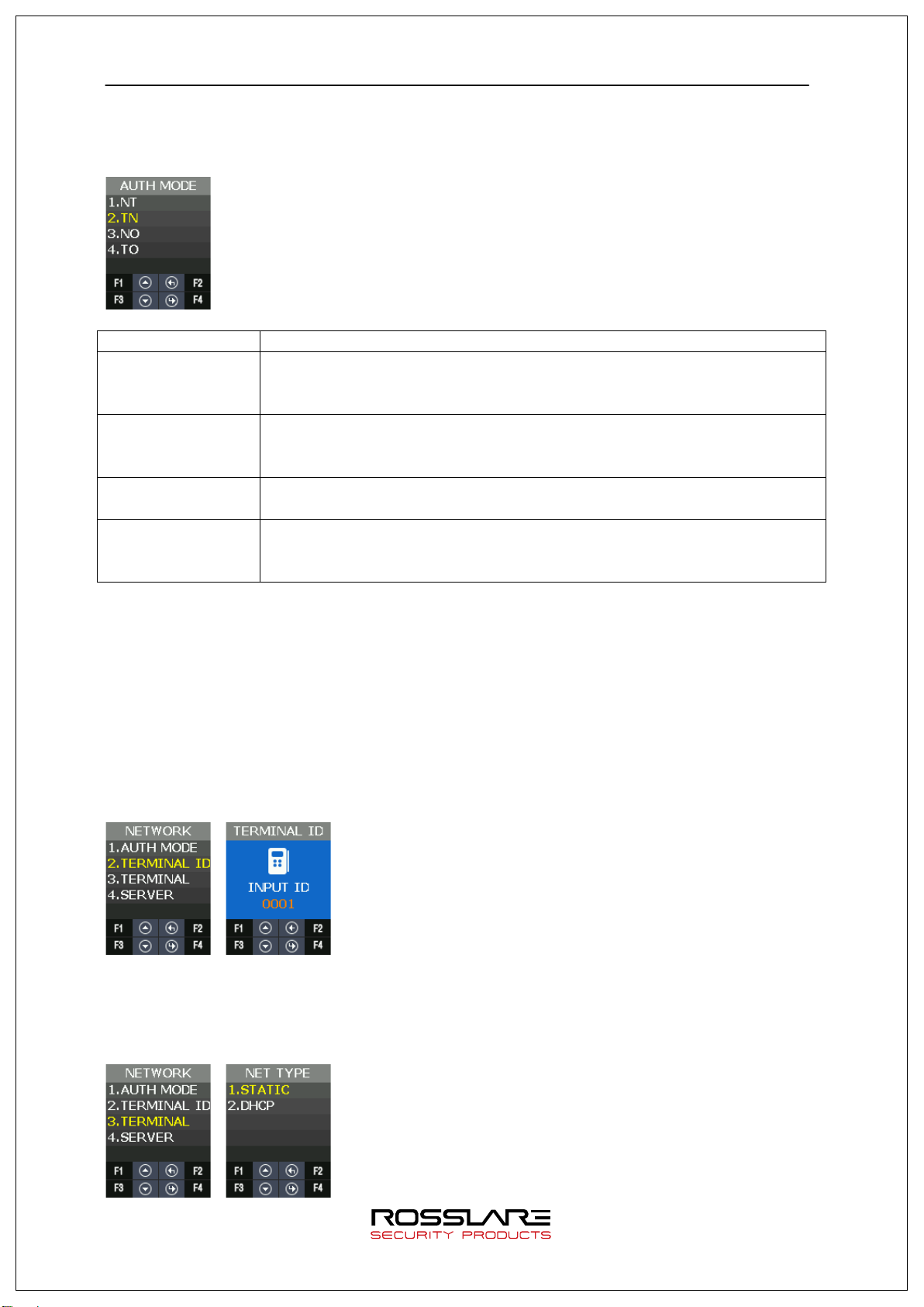
3.5.1. AUTH Mode
Authentication mode means the authentication priority to determine whether authentication
Page 37
AY-B9250BT User Guide 37
Server/Terminal
Server Terminal
Server
Server only
Terminal
Terminal only
processing is done in the terminal or the server when user-authentication.
It is a valid setting only when using the network. All authentication log is sent to server
through the network.
AUTH MODE Explanation
After trying to do server authentication at first, terminal authentication
is processed.
Terminal/Server
Terminal Server
After trying to do terminal authentication at first, server authentication
is processed.
Authentication is processed only in server.
Authentication is processed only in terminal.
Even if it is “Terminal Only”, authentication log is sent to server.
★ In Server Only” mode, if the network is disconnected, all the authentication is processed in
fail. If the mode is not “Server Only” (Server/Terminal, Terminal/Server, Terminal) and the
network is disconnected, authentication is processed in the base of DB in the terminal.
3.5.2. Terminal ID
Terminal ID is a valid information only when using the network, and it can be set in the range
of 1~200.
If a user registered in the terminal exists, you can’t change the Terminal ID.
3.5.3. Terminal
It is used when setting the network information in the terminal.
Page 38

AY-B9250BT User Guide 38
SUBNET MASK
255.255.255.0
GATEWAY
192.168.0.1
Function Key
Function Explanation
F2
Move to left
F4
Move to right
Server IP
192.168.0.2
Port number
7332
Network setting in the terminal can be set in Static IP and DHCP.
STATIC: Set the value as a user wants.
DHCP: Allocated flexibly. (It can be operated normally when using the router supporting
D HC P. )
If STATIC is used, it is used when setting IP, Subnet mark and Gateway address of the
terminal.
The following is the default setting value.
Category Default Setting Value
Terminal IP 192.168.0.3
It can set the address value as follows.
F1 Increase the setting value
F3 Decrease the setting value
F4 Long Save the setting value
3.5.4. Server
When the terminal accesses in server through the network, set the information.
Default setting value is as follows.
Category Default Setting Value
3.6. OPTION Menu
User menu has the same function as follows.
Page 39

AY-B9250BT User Guide 39
LOCKING
NO USE / USE
Category Explanation
ATTEND TYPE
AUTO TNA
SCREEN LANGUAGE
SHOW ID
USER LOGO
USER ID LEN
DATE
SAVE LOGO SAVE
IMAGE SAVE
TIMEOUT RE SULT
NET ERROR
PING
3.6.1. ATTEND
TNA related menu is configured.
Category Explanation
TYPE When Function Key is used in time and attendance option, it is used.
AUTO TNA Use to determine whether to remain Function Key or not shown in the default
screen.
TYPE 3.6.1.1.
It is used when setting ATTEND mode. If setting ATTEND mode, ATTEND mode is displayed in
the screen when pressing Function Key shortly (F1~F4) in the default screen.
Page 40

AY-B9250BT User Guide 40
NONE
F00 is only displayed in default screen.
F02 are displayed in default
is recognized and, F01, F02, F03, F04 are displayed in
Function Key
Meaning
F01
CLOCK-IN MODE
F02
CLOCK-OUT MODE
F04
CHECK-IN MODE
Category
Explanation
NO
The TNA mode is automatically returned into F00 after 10 seconds.
Category
Explanation
LANGUAGE
Change the language which is displayed in the screen and is spoken.
You can set whether the logo image for customers is used or not in the
DATE
It is used when modifying Year/ Month/ Day and time displayed in the
Mode Explanation
F1~F2 F1~F2 Function Key is recognized and F01,
screen.
F1~F4 F1~F4 Function Key
default screen.
F1~F49 F1~F4 Function Key is recognized and F01, F02, F03, F04, F11~F49 are
displayed.
F00 ACCESS MODE
F03 CHECK-OUT MODE
F11~F49 EXPANDED MODE
TNA mode (F00~F49) is converted into F00 after 10 seconds if you don’t use AUTO TNA.
AUTO TNA 3.6.1.2.
AUTO TNA is the menu to determine whether to remain continually the setting TNA mode or
not.
YES The TNA mode is continuously displayed.
3.6.2. Screen
The screen display related menu is configured.
SHOW ID When authentication succeeds, you can set whether showing ID or not.
USER LOGO
default screen.
USER ID LEN It is used when modifying the length of user’s ID.
Page 41

AY-B9250BT User Guide 41
Category
Explanation
USE
When authentication successes, it shows user’s ID on the screen.
default screen.
Language 3.6.2.1.
It is used to change the voice language and menu text displayed on the screen.
Voice guidance is available in English, Korean, Indonesian, Thai, Arabic, Spanish, Portuguese,
French, Russian, Farsi, Japanese, and Chinese.
Language support for all menu text is in English, Korean, Indonesian, Spanish, Portuguese,
French, Japanese and Chinese.
Language support for some text is in Farsi, Arabic, Thai and Russian.
SHOW ID 3.6.2.2.
It is used to determine whether to show your ID at the time of authentication success window.
NO USE Do not show your ID at the time of authentication success Screen Yes "****"
When authentication successes, it doesn’t show user’s ID on the screen.
For example, “****”.
For example, “****”.
USER LOGO 3.6.2.3.
It is used to determine whether the displayed image shows the customer’s logo or not in the
default screen.
Page 42

AY-B9250BT User Guide 42
NO USE
Use basically the provided default image
USE
Use the customer’s logo image
update the
customer’s image through the server first and then the
Category Explanation
To use the customer’s logo image, you should
customer’s image is displayed in the default screen.
When editing the customer’s image, it should be edited in the
red box as the left picture.
pixel, and the red box image size is 102 (W) x74 (H) pixel.
The full image size is 128 (W) x160 (H)
128
160
USER ID LEN 3.6.2.4.
It is used to change the length of user’s ID. If changing the user’s ID, it should change in the
absence of a DB because it affects user’s DB that is internally registered. The setting range
can be set from 4 to 16.
If a user registered in the terminal exists, you can’t change the length of User ID.
74
52
102
26
Page 43

AY-B9250BT User Guide 43
DATE 3.6.2.5.
It is used to select the order of Year, Month and Day displayed in the default screen.
YY: Year
MM: Month
DD: Day
Through SETTING, you can set current Year, Month, Day and Time.
3.6.3. SAVE
It is the menu including the function related to SAVE.
LOG SAVE 3.6.3.1.
It is used to set whether to save the authentication log in memory or not.
The default setting is YES.
Page 44

AY-B9250BT User Guide 44
IMAGE SAVE 3.6.3.2.
It is used to set whether to save the captured photo from camera when authentication
successes or fails. The default setting is Fail.
3.6.4. TIMEOUT
It is the menu that has the setting related with timeout.
RE SULT 3.6.4.1.
It is used to set the authentication result display how long it keeps for a seconds.
The setting range can be set from 0 to 5 seconds. If it set to 0, then don’t display the
authentication result.
NET ERROR 3.6.4.2.
If it does not communicate with the server over a period of time, it is used to set whether
there is a network communication error.
If PING doesn’t come for a setting time in the server, it retries to connect the terminal.
The setting range is available for 60~600 seconds.
Page 45

AY-B9250BT User Guide 45
PING 3.6.4.3.
It sets the cycle that terminal sets PING command to the server.
The setting range is available for 30~255 seconds.
3.6.5. LOCKING
Locking mode is the function that it rejects the authentication of all users until the
administrator enters the menu and releases the locking mode.
The default setting is NO USE.
The default screen is displayed as follows when setting to use locking mode.
Page 46
AY-B9250BT User Guide 46
Category
Explanation
BEEP
Set Beep Sound.
VOICE
Set Voice Sound
BLE
BLE registration mode
TAMPER
Set the alarm when opening terminal case.
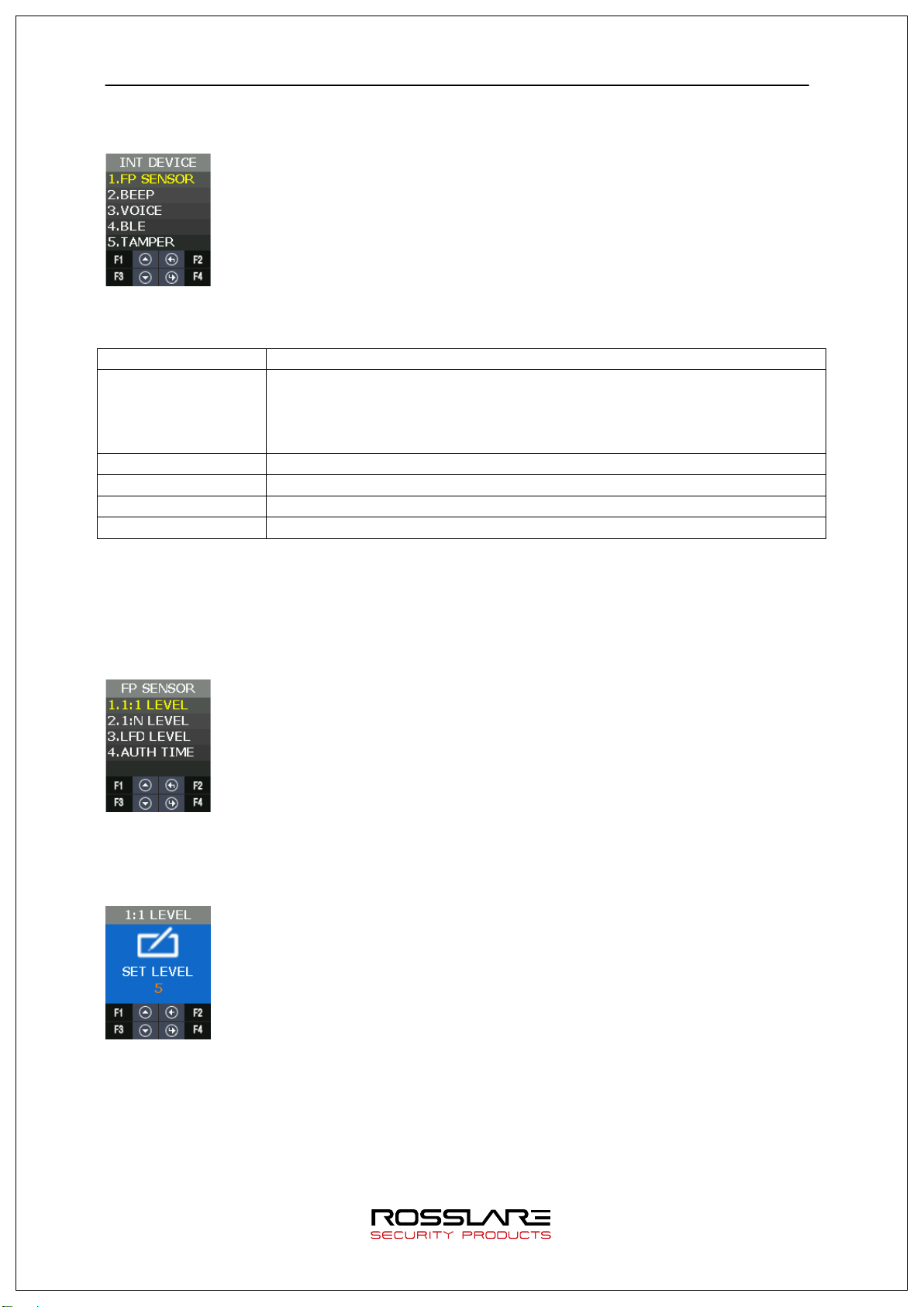
3.7. INT DEVICE Menu
INT DEVICE menu has the features as follows.
FP SENSOR 1:1 LEVEL
1: N LEVEL
LFD LEVEL
AUTH TIME
3.7.1. FP SENSOR
For the fingerprint recognition, it sets for the user registration and authentication about the
module installed inside.
1:1 LEVEL 3.7.1.1.
It is the authentication level used when it tries 1:1 fingerprint authentication.
Page 47
AY-B9250BT User Guide 47
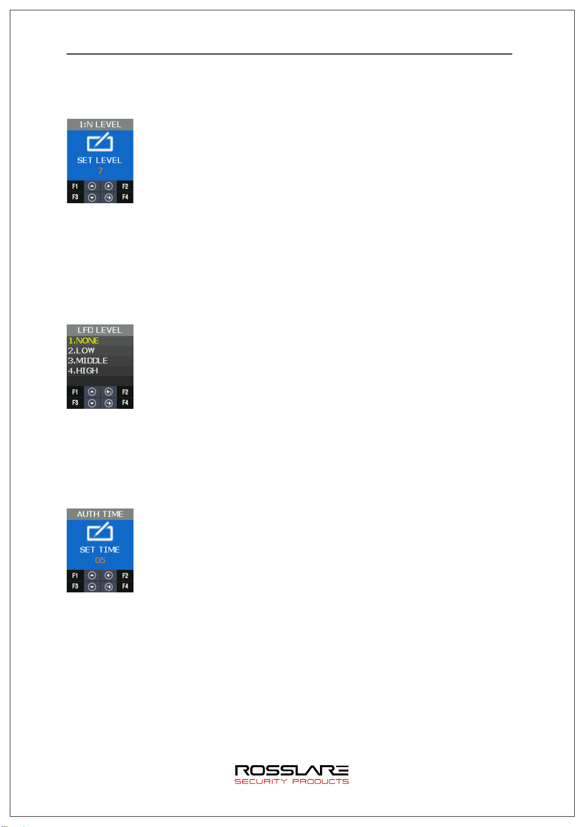
1: N LEVEL 3.7.1.2.
It is the authentication level used when it tries 1: N fingerprint authentication.
LFD LEVEL 3.7.1.3.
It sets LFD LEVEL to prevent the duress fingerprint.
If setting LFD LEVEL higher and higher, the ability to prevent the input of duress fingerprint
produced by rubber, paper, film, and silicon etc. reinforces but too dry fingerprint cannot be
input well. Also the authentication speed can be slow.
AUTH TIME 3.7.1.4.
It means the maximum time to process 1: N authentication. If the authentication time
exceeds, authentication timeout occurs.
seconds.
The authentication time is 2 to 10 seconds, the default is 5
Page 48

AY-B9250BT User Guide 48
3.7.2. BEEP
It informs key touch, authentication success, and failure as beep and sets the beep level. The
beep level is available from 0 to 3.
3.7.3. VOICE
It supports the notice such as authentication success/failure and authentication retrial. It sets
the authentication level. The voice level is available from 0 to 5.
3.7.4. BLE
When registering the terminal in Administrator’s App, this menu is required.
By using this menu, it can make the terminal BLE READY. Only if the terminal is BLE READY, it
can perform the registration procedure of the terminal after the administrator app accesses
the terminal.
When pressing F3 long in the default screen of the terminal, it performs same operation with
this menu.
Regarding the method to register the terminal in the administrator APP, please refer 3.2 How
to register the terminal in the administrator App.
3.7.5. TAMPER
When disassembling the terminal randomly, it sets whether to sound the alarm.
Page 49

AY-B9250BT User Guide 49
Category
Explanation
DOORLOCK
It sets the control device to lock through the internal relay.
Category
Explanation
2.
If selecting 1. NO ALARM, even if disassembling the terminal, the alarm doesn’t sound but
icon is displayed.
If selecting 2. ALARM,
icon displays and the beep sounds in at regular intervals.
3.8. EXT DEVICE Menu
EXT DEVICE has the features as follows.
RS485 It sets the devices using RS485.
WIEGAND It sets the device using WIEGAND.
3.8.1. DOORLOCK
It is the menu to set lock device (Strike, Motor type door lock) by using LOCK1 and LOCK2
port.
LOCK1 type 3.8.1.1.
NONE No Use
Strike/OK When connecting the light to mark authentication success/failure or
STRIKE/OK.
MOTOR1 When connecting Motor lock
Page 50

AY-B9250BT User Guide 50
FAIL IND
When connecting the light to mark authentication failure in Lock 2
MOTOR2
When connecting motor lock
LOCK1 OPEN TIME 3.8.1.2.
It sets the time to give the signal when LOCK 1 sets 2. STRIKE/OK. Strike type means the
time from opening to locking the door after authenticating.
the input range is 1 to 20 seconds.
The default value is 3 seconds and
LOCK2 type 3.8.1.3.
NONE When not using
LOCK2 OPEN TIME 3.8.1.4.
If Lock 2 sets FAIL IND, it sets the time to give the signal.
input range is 1 to 20 seconds.
The default value is 3 seconds and the
OPEN ALARM 3.8.1.5.
When the door open time expires and the door open alarm time is exceeded, the alarm sounds.
The default value is 5 seconds and the input range is 0 ~ 20 seconds. If it is set to 0, it does not beep. If
it is set to 1 ~ 20 seconds, it does beep.
Door open time Open alarm time
alarm
DOOR OPEN state
Page 51

AY-B9250BT User Guide 51
DM0 3.8.1.6.
DM0(Door Monitor 0) is the input port and it is used to detect the signal state of door open.
DM1 3.8.1.7.
DM1(Door Monitor 1) is the input port and it is used to detect the signal state of lock.
DM2 3.8.1.8.
DM2(Door Monitor 2) is the input port and it is used to detect a various of sensor and alarm.
For example, if connecting with fire sensor, it should set 4. FIRE N/O or 5. FIRE N/C and it
may cause fire alarm and icon in case of fire. In case of fire, the door automatically opens for
safe t y.
Page 52
AY-B9250BT User Guide 52
NONE
It doesn’t use RS485.
LC010
Lock Controller
LC015
Lock Controller
SR100
FP Dummy Reader
and then
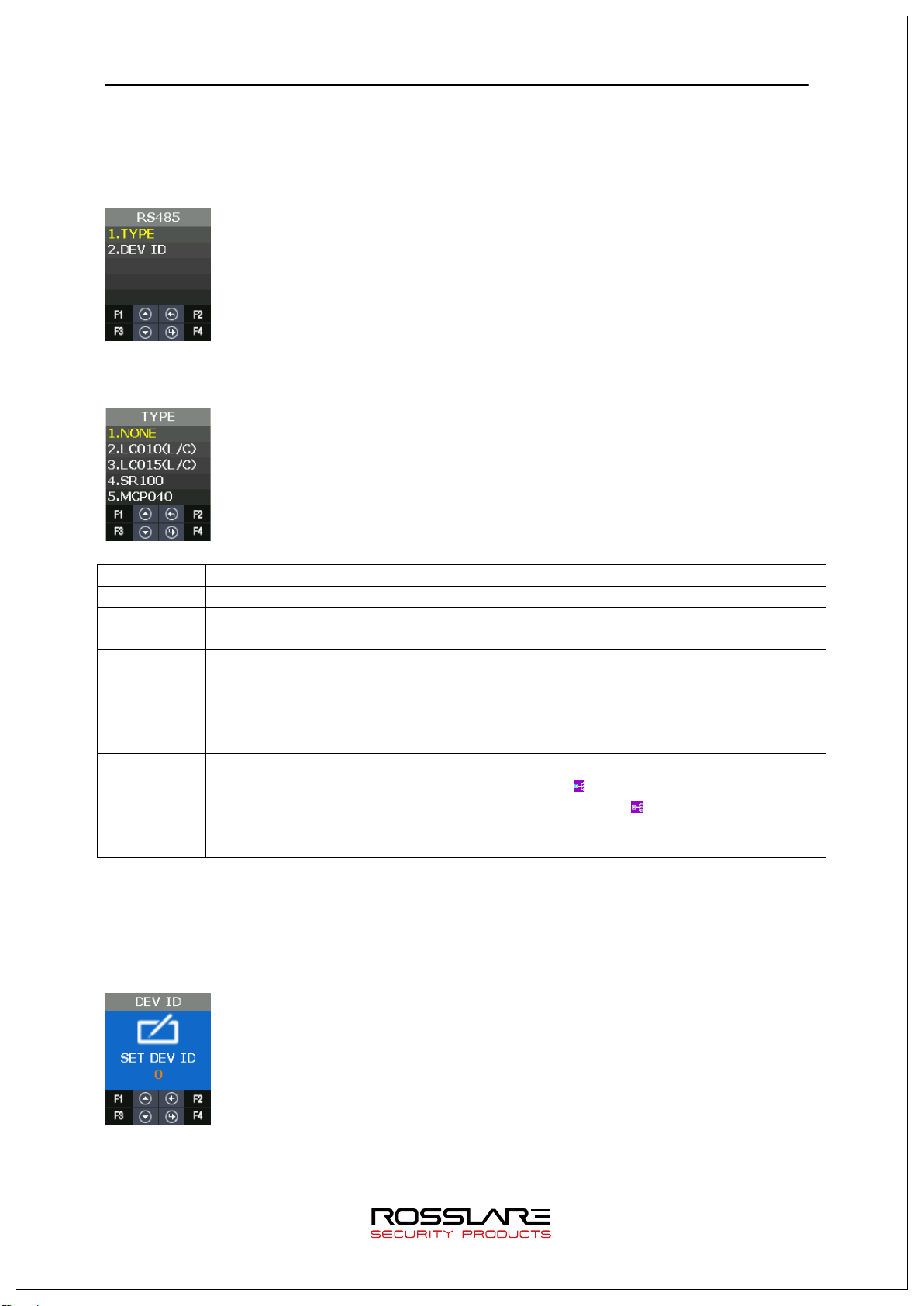
3.8.2. RS485
It is the setting for the device with RS485 communication to interface with external.
TYPE 3.8.2.1.
TYPE Explanation
It controls LOCK through the other external module.
It controls LOCK through the other external module.
When it installs the other FP dummy reader device in external
operates, it is used.
MCP040 Terminal operates as the dummy reader.
If Terminal is connected with MCP040 device,
ult screen. If Terminal is not connected with MCP040,
icon is displayed in the defa
icon is displayed.
The authentication result is determines whether or not successful by MCP040.
RS485ID uses 1~7.
DEV ID 3.8.2.2.
DEV ID is the ID that distinguishes devices and it can be set up 0-7 during RS484
communication.
3.8.3. WIEGAND
Page 53

AY-B9250BT User Guide 53
NONE
WIEGAND input port is not used.
WIE34BIT
MIFARE Card Modules
Category
Explanation
WIE34BIT
MIFARE Card Modules
CUSTOM
Use Access Manager program and set Wiegand format.
WIEGAND supports each one of Input port and Output port.
WIRE-INPUT 3.8.3.1.
It is used to set the input type when working with the device connected into WIEGAND input
port.
Category Explanation
WIE26BIT EM, HID26 Card Module
CUSTOM Use Access Manager program and set Wiegand format.
WIRE-OUTPUT 3.8.3.2.
NONE WIEGAND output port is not used.
WIE26BIT EM, HID26 Card Module
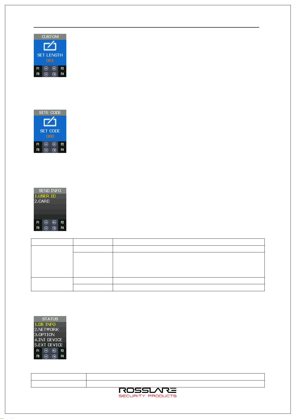
CUSTOM BIT LENGTH 3.8.3.3.
It can set BIT length as 1~128.
Page 54
AY-B9250BT User Guide 54
SEND INFO
Type
None
STATE information
Explanation
DB INFO
User DB, Authentication log data
SITE CODE 3.8.3.4.
It is used to set the value of Site Code that is sent to WIEGAND output port.
SEND INFO 3.8.3.5.
It is used to select the transmitting data by the output port.
USER ID 26 Bit E.Parity(1)+ Site Code(8bit) + ID(16bit) + O.Parity(1)
34 Bit E.Parity(1)+ Site Code(8bit) + ID(24bit) + O.Parity(1)
If the length of the User ID greater than 8, and sent in the
following format without site code:
E.Parity(1)+ ID(32bit) + O.Parity(1)
Card 26 Bit E.Parity(1) + 24bit Card Number+ O.Parity(1)
34 Bit E.Parity(1) + 32bit Card Number + O.Parity(1)
3.9. STATUS Menu
STATE menu has the following features.
Page 55

AY-B9250BT User Guide 55
OPTION
TNA, Screen setting, Saving, Time out, Lock mode
INT DEVICE
Display the setting state related to the internal device.
EXT DEVICE
Display the setting state related to the external device.
NETWORK The setting information related to network
I/O PORT Display the current signal of Input / Output port that interfaces with
outside.
VERSION Display the version of the equipped device in the terminal.
3.9.1. DB INFO
It displays User’s DB information and the authentication log information.
3.9.2. NETWORK
It displays the network setting value.
3.9.3. OPTION
It displays the option setting value.
3.9.4. INT DEVICE
It displays the setting value related to the internal device.
Page 56

AY-B9250BT User Guide 56
3.9.5. EXT DEVICE
It displays the setting information related to the external device.
3.9.6. I/O PORT
It reflects the current I/O Port state and displays it on the screen.
Output Port: LOCK1, LOCK2
Input Port: DM0~DM2, W0IN, W1IN, INSIDE Open, Tamper
When the input port shorts GND, the signal modifies from HIGH to LOW.
3.9.7. VERSION
It displays the equipped module in the terminal and other version information.
Page 57

AY-B9250BT User Guide 57
INITIALIZE
CONFIG
REBOOT
REBOOT
3.10. RECOVERY Menu
RECOVERY has the features as follows.
Category Explanation
LOG DB
FACTORY
SELF TEST INT DEVICE
EXT DEVICE
BACKUP LOG EXPORT
USER EXPORT
USER IMPORT
FW UPDATE
3.10.1. INITIALIZE
It is used to initialize CONFIG, LOG DB, and FACTORY in the terminal.
CONFIG 3.10.1.1.
It is used to initialize the modified setting value in the menu as the default value when shipping from
facto r y.
If a user registered in the terminal exists, you can’t initialize the configuration information.
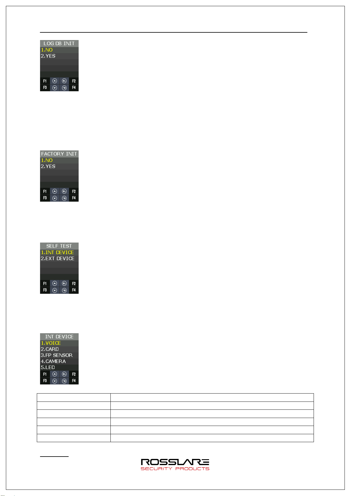
LOG DB INIT 3.10.1.2.
It is used to delete the user authentication log saved in the terminal.
Page 58
AY-B9250BT User Guide 58
VOICE
Voice output test
CARD
Card recognition test
LED
LED output test
FACTORY INIT 3.10.1.3.
If trying FACTORY INIT, setting data, authentication log data, and user registration
information are initialized as setting state when shipping from factory.
★ It should be careful because the current data can be lost when you setting wrong.
3.10.2. SELF TEST
It is used when the terminal tests the operation state about internal & external device by itself.
INT DEVICE 3.10.2.1.
It could test VOICE, CARD, FP SENSOR, CAMERA and LED equipped internally by itself.
FP SENSOR Fingerprint recognition test
CAMERA Camera equipment test
Voice Test
Category Explanation
Page 59

AY-B9250BT User Guide 59
When authentication successes, it repeats and play voice guidance.
Card Test
As you see below, the screen displays “INPUT CARD” state at first.
When recognizing the card, “Success” screen displays and it returns “INPUT CARD” state
again. If you want to stop testing, press F2.
FP Sensor Test
FP Sensor Test is used to test the operation state of FP sensor from terminal.
Input your fingerprint twice, if they are same, it shows “Success” screen.
Otherwise, if not, it shows “Failure” screen.
Camera Test
It is used to check whether the camera state is normal in the terminal to capture photos.
LED Tes t
It is used to check whether the state is normal about RED, GREEN and BLUE LED used to
inform the operation state.
At intervals of 2 seconds, RED, GREEN and BLUE LED changes from ON to O F F.
Page 60

AY-B9250BT User Guide 60
DOORLOCK
Lock1, Lock2
SENSOR IN
DM0
EXT DEVICE 3.10.2.2.
It can test the features related to the external device by itself.
Category Explanation
DM1
DM2
INSIDE OPEN
TAMPER
DOORLOCK Test
It is used to check the state of LOCK1, LOCK2 OPEN /CLOSE from the terminal.
The procedure is as follows.
SENSOR IN
It is used to check the signal state about the input port.
When the port shorts GND, if signal changes LOW, it is normal.
Page 61
AY-B9250BT User Guide 61
USB memory
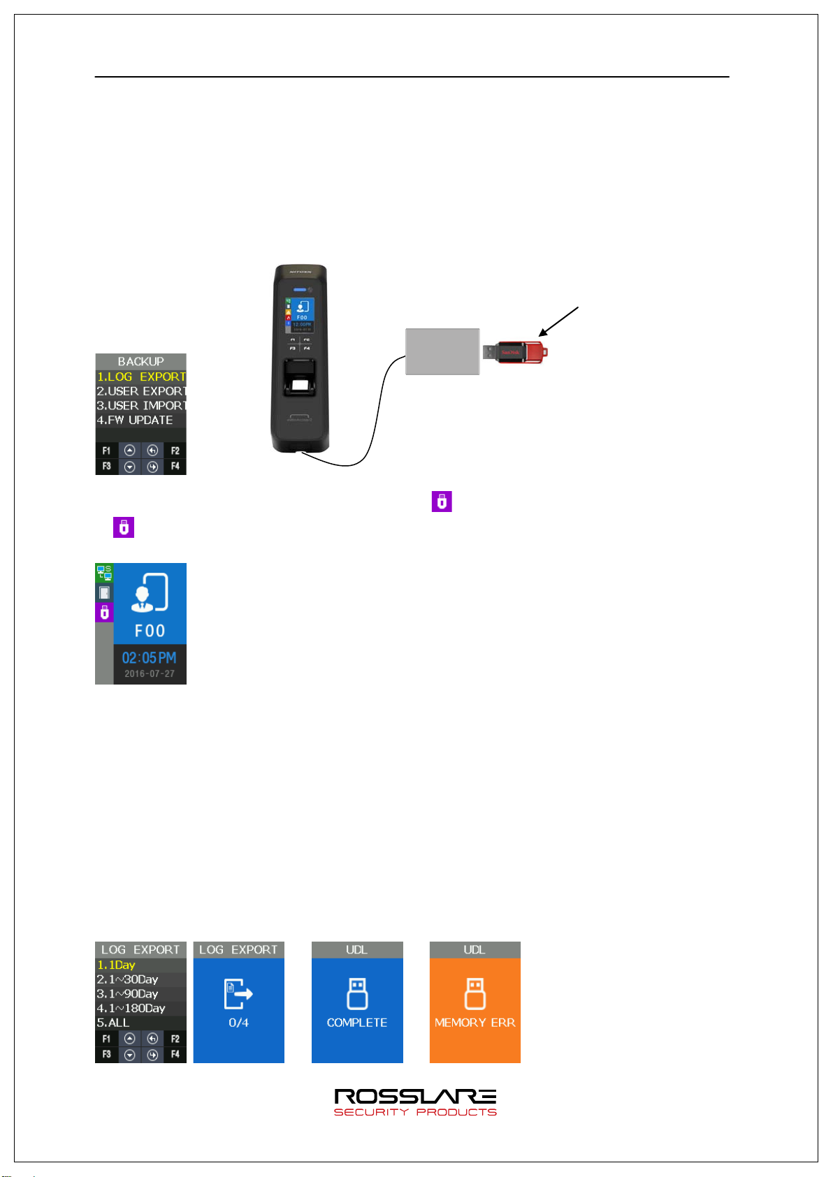
3.10.3. BACKUP
When the saved data from the terminal sends to USB by using UDL device or brings the data
from USB memory and then applies it, it is used. It is available only when the UDL module is.
UDL is the option module, so it is not basically provided. If you want to get more information
about UDL module, please contact customer service. USB memory recommends using
SanDisk.(NOTICE: UDL Device is not supported for all USB memory.
depending on the USB memory size, manufacturer, and method.
)
UDL
module
UDL module may not work
If Terminal detect UDL Device and USB memory, icon is displayed in the default screen.
icon isn’t displayed, all backup function doesn’t operate.
If
LOG EXPORT 3.10.3.1.
The saved log data from terminal saves in USB memory through UDL (User Data Downloader
module).
Only the log data in the selected period sends to USB and saves it through UDL.
The file name saved in USB memory is divided by period as follows.
1. 1Day: L1Day.NLG,
2. 1~30Day: L30Day.NLG
3. 1~90Day: L90Day.NLG
4. 1~180Day: L180Day.NLG
5. ALL: ALL.NLG
or
Page 62

AY-B9250BT User Guide 62
USER EXPORT 3.10.3.2.
The saved User DB from the terminal saves in USB memory through UDL.
It saves as USER.NDB file.
or
USER INPUT 3.10.3.3.
It reads the user DB from USB memory through UDL and adds it in terminal user DB.
If inputting user DB in the terminal, all existing user DB are deleted.
If you need the existing user DB saved in the terminal, back up first and try to input the user.
It opens USER.NDB file in USB memory and brings into the terminal through UDL.
The user registration data that you brought is reflected in the internal DB and added.
※ CAUTION: If you press F2 Key to stop in READ state, user loading fails.
or
FW UPDATE 3.10.3.4.
It is used when reading the firmware from USB memory through UDL and updating the
terminal firmware.
Firmware proceeds only when there is FW.NFW file name in USB memory.
. or
3.10.4. REBOOT
It is used when rebooting the terminal.
Page 63

AY-B9250BT User Guide 63
Appendix 1. Glossary
<Glossary >
Administrator (Admin)
- The administrator can access the terminal menu mode. He/she has the authority to
add/modify/delete terminal users and to change the operating environment by changing
settings.
- If there is no registered administrator in the terminal, anybody can access to the terminal
menu and change settings. It is recommended that more than one administrator
be registered in the terminal.
- The administrator has the authority to change critical environmental settings of the
fingerprint reader. So, special attention is required to its registration and operation.
1:1 Authentication
- The user fingerprint is verified after entering User ID or Card.
- Only User ID or the user fingerprint registered to the card is compared. This is called
One-to-One Authentication.
1: N Identification
- The user is searched only by the fingerprint.
- The same fingerprint as the input fingerprint is identified among the registered
fingerprints without User ID or Card entered. This is called One-to-N Identification.
Authentication Level
- As a level used for fingerprint authentication, it is displayed in Step 1 to 9.
Authentication cannot be allowed before the degree of match between two fingerprints
is higher than the set authorization level.
- The higher authentication level may ensure the higher security. But it requires the
relatively high concordance rate. When authenticating User ID, it high likely to deny
authentication.
- 1:1 Level: Authentication level applied when 1:1 authentication
- 1: N Level: Authentication level applied when 1: n authentication
Authentication Method
- It refers FP (Fingerprint) Authentication, RF (Card) Authentication and a various types
of authentication methods made by each of a combination.
LFD (Live Finger Detection): Fake fingerprint prevention function
- The LFD allows only actual fingerprints to be entered, except for any fake fingerprints
made of rubber, paper, film, and silicon and the like.
Page 64

AY-B9250BT User Guide 64
Appendix 2. Declaration of Conformity
This device complies with Part 15 of the FCC Rules. Operation is subject to the following
two conditions:
- This device may not cause harmful interference.
- This device must accept any interference received, including interference that may
cause undesired operation.
Changes or modifications not expressly approved by the party responsible for compliance
could void the user's authority to operate the equipment.
This equipment has been tested and found to comply with the limits for a Class B digital
device, pursuant to part 15 of the FCC Rules. These limits are designed to provide reasonable
protection against harmful interference in a residential installation. This equipment generates,
uses, and can radiate radio frequency energy and, if not installed and used in accordance with
the instructions, may cause harmful interference to radio communications. However, there is
no guarantee that interference will not occur in a particular installation. If this equipment does
cause harmful interference to radio or television reception, which can be determined by
turning the equipment off and on, the user is encouraged to try to correct the interference by
one or more of the following measures:
Reorient or relocate the receiving antenna.
Increase the separation between the equipment and receiver.
Connect the equipment into an outlet on a circuit different from that to which the receiver
is connected.
Consult the dealer or an experienced radio/TV technician for help.
CAUTION: Exposure to radio frequency radiation
This equipment should be installed and operated with a minimum distance of 20 cm
between the radiator and your body.
Page 65

AY-B9250BT User Guide 65
Appendix 3. Radio Equipment Directive (RED)
Rosslare hereby declares that the AY-H6355BT is in compliance with essential
requirements and other relevant provisions of Directive 2014/53/EU.
Page 66

AY-B9250BT User Guide 66
Appendix 4. RoHS Directive
Under our sole responsibility that the following labeled AY-U9xxBT is tested to conform
to the Restriction of Hazardous Substances (RoHS) directive – 2011/65/EU – in
electrical and electronic equipment.
Page 67

AY-B9250BT
CERT
ISO 9001
ISO 14001
Asia Pacific, Middle East, Africa
Rosslare Enterprises Ltd.
Kowloon Bay, Hong Kong
Tel: +852 2795-5630
Fax: +852 2795-1508
support.apac@rosslaresecurity.com
United States and Canada
Rosslare Security Products, Inc.
Southlake, TX, USA
Toll Free: +1-866-632-1101
Local: +1-817-305-0006
Fax: +1-817-305-0069
support.na@rosslaresecurity.com
Europe
Rosslare Israel Ltd.
22 Ha'Melacha St., P.O.B. 11407
Rosh HaAyin, Israel
Tel: +972 3 938-6838
Fax: +972 3 938-6830
support.eu@rosslaresecurity.com
Latin America
Rosslare Latin America
Buenos Aires, Argentina
support.la@rosslaresecurity.com
China
Rosslare Electronics (Shenzhen) Ltd.
Shenzhen, China
Tel: +86 755 8610 6842
Fax: +86 755 8610 6101
support.cn@rosslaresecurity.com
India
Rosslare Electronics India Pvt Ltd.
Tel/Fax: +91 20 40147830
Mobile: +91 9975768824
sales.in@rosslaresecurity.com
0709-0960679+00
 Loading...