

Page 1
BULLETIN 600T
ISO Valves and
Serial Bus Communication
with Turck
Modular I/O System
Premium Pneumatic Controls Since 1921
TM
ControlNet
TM
PROFIBUS
®
DeviceNet
TM
CANopen
Page 2
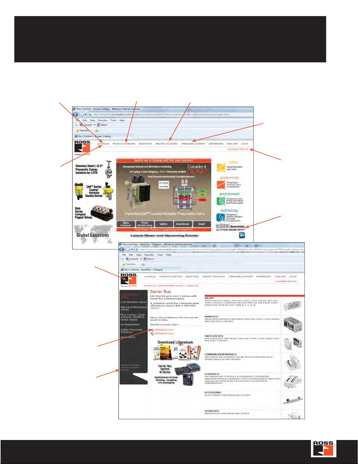
ROSS' website is the most complete and up-to-date source for product research and documentation.
Search results produce downloadable documentation or request for quote (RFQ).
Additional product information or CAD files are easily requested from Technical Service Team.
Additional information such as certifications, links and associations is also available.
Search for Products by Model Number,
descriptions or Search Repair Kits
by Product Model Number
Quick Order
by Part Number
Visit our website for
New released Products
Industry Solutions section includes white papers,
published articles, applications, and product
selection for specific industry segments
Download Catalogs, Bulletins,
find T echnical Documentation
and Information
Contact a ROSS
Inside Sales Team member
Sign Up for ROSS' e-News,
a Monthly Newsletter
Click on the ROSS Logo to
always return to Home Page
Find the right Electronic Data
Sheet (EDS) file for your
Serial Network
Standard Warranty and
Cautions
www.rosscontrols.com
2 © 2012, ROSS CONTROLS
®
. All Rights Reserved.
Page 3

Table of Contents
Standard Definitions .......................................................................................................................................4
Serial Bus Systems
ISO Size 00 & 0 Valves, Series W66 - Ordering Code
Plug-in, ISO Size 00 & 0 Valves Series W66 (15407-2)
Spool and Sleeve Valves for ISO Sub-Bases Size 1, 2 & 3 Valves, Series W65 (5599/II)
Plug-in, Series W66 (15407-2)
Size 00 & 0 Manifold & Sub-Base Kits .....................................................................................................10
Plug-in, Series W65 (5599-2)
Size 1, 2 & 3 Manifold & Sub-Base Kits ...................................................................................................11
End Plate Kits Size 00 & 0, Series W66
End Plate Kits Size 1, 2 & 3, Series W65
Accessories
Service & Repair Kits
Technical Information
.............................................................................................................................................13-15
........................................................................................................................................5
..................................................................................6
.................................................................................7
...........................8-9
.......................................................................................................12
.....................................................................................................12
...................................................................................................................................16
....................................................................................................................................17
TURCK Modular Industrial I/O System BL67
Overview .............................................................................................................................................18-19
Selection Guide .......................................................................................................................................20
Gateways
DeviceNet ...............................................................................................................................................21
Ethernet .............................................................................................................................................22, 23
Profibus-DP .............................................................................................................................................24
CANopen ...........................................................................................................................................25, 26
Modules
Discrete ..............................................................................................................................................29-36
Analog .....................................................................................................................................................42
Serial .......................................................................................................................................................41
Power Feed ..............................................................................................................................................43
Base Modules
Accessories ..................................................................................................................................................42
Standard Cautions
TURCK products Warranty, Terms and Conditions
ROSS products Standard Warranty
Global Locations
...............................................................................................................................................44
.......................................................................................46
..............................................................................................................47
...........................................................................................................................................48
3www.rosscontrols.com
Page 4
Standard Definitions
!
15407-1: Drop-cord Standards
for Size 0 (26mm) & Size 00 (18mm) Wide Valves
15407-2: Plug-in Standards
for Size 0 (26mm) & Size 00 (18mm) Wide Valves
5599-1: Drop-cord Standards for Sizes 1, 2, 3
5599-2: Plug-in Standards for Size 1, 2, 3
F AILURE OR IMPROPER SELECTION OR IMPROPER USE OF THE PRODUCTS AND/OR SYSTEMS
WARNING
This document and other information from ROSS CONTROLS®, its subsidiaries and authorized distributors provide product
and/or system options for further investigation by users ha ving technical expertise. It is important that you analyze all aspects
of your application including consequences of any failure , and review the information concerning the product or system in the
current product catalog. Due to the variety of operating conditions and applications for these products or systems, the user,
through its own analysis and testing, is solely responsible for making the final selection of the products and systems and
assuring that all performance, safety and warning requirements of the application are met.
The products described herein, including without limitation, product features, specifications, designs, availability and pricing, are
subject to change by ROSS CONTROLS and its subsidiaries at any time without notice.
DESCRIBED HEREIN OR RELATED ITEMS CAN CAUSE DEATH, PERSONAL INJURY AND
PROPERTY DAMAGE.
4 © 2012, ROSS CONTROLS
®
. All Rights Reserved.
Page 5
TM
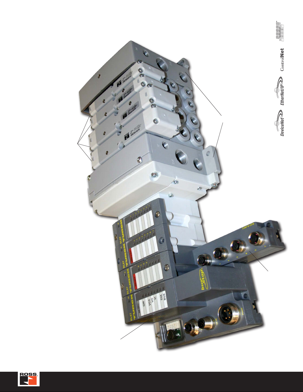
• Centralized Serial Bus system
• Pneumatics and I/O are in close proximity to one another
• I/O density per module = 8
Series W66 18mm
ISO 15407-2 Valves
End Station Kit
• A complete Serial Bus communication offering for all ISO valves
Serial Bus System I/O - Centralized Configuration
• UL, CE, CSA certifications (as marked)
Adapter
Communication
www.rosscontrols.com
M12, Input or
Output Module
5
Page 6
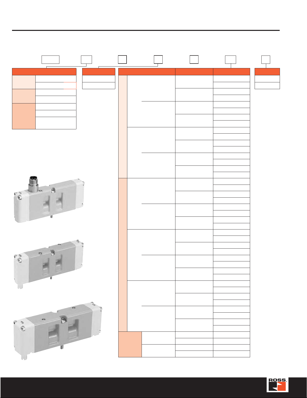
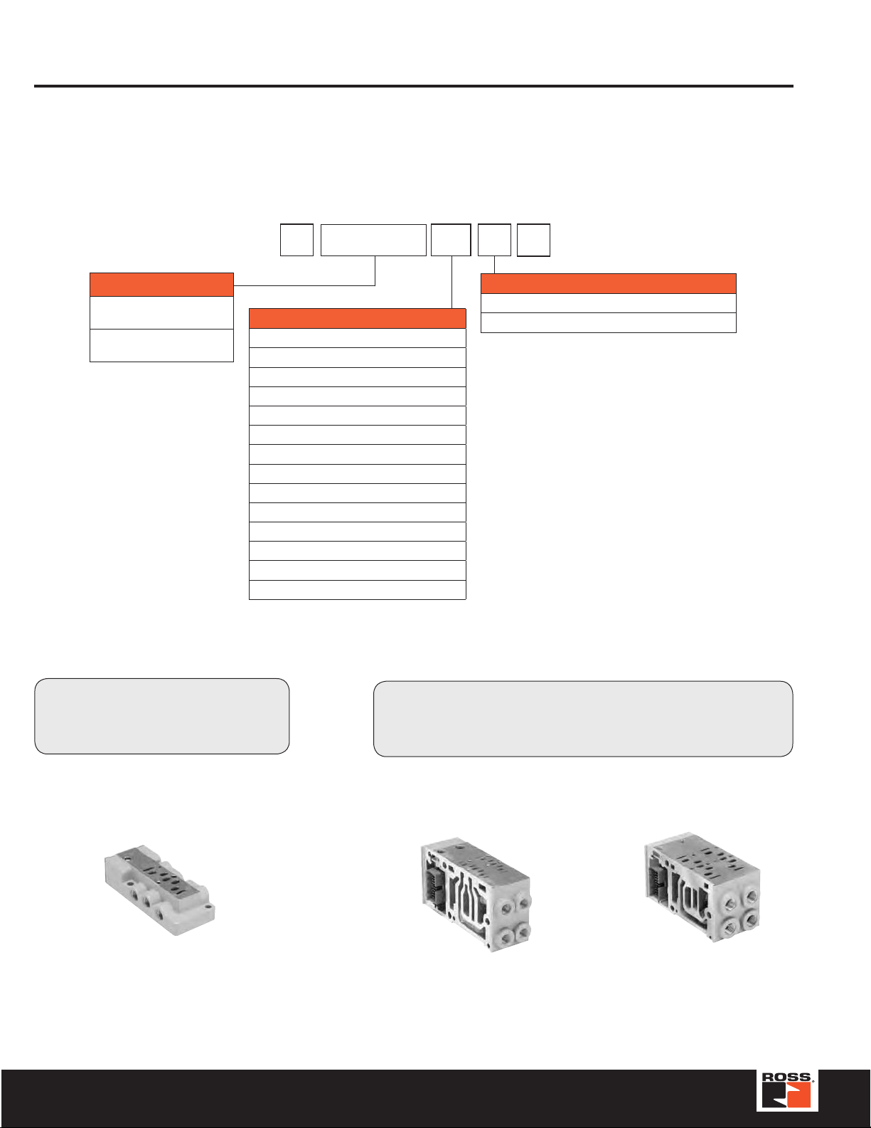
ISO Size 00 & 0 Valves Series W66
HOW T O ORDER
(Choose your options (in red) to configure your valve model number.)
W66 76 A 0 4 01 W
Function*
4-Way
2-Position
4-Way
3-Position
Dual
3-Way
2-Position
Remote Pilot 56
Solenoid Pilot 76
Remote Pilot 57
Solenoid Pilot 77
Normally Open 70
Normally Closed 75
NC / NO
NC - 14 End
78
Basic Size
Size 00 (18mm) 0
Size 0 (26mm) 1
* Be sure to choose Options from the correct list. For example,
if a Function of 4-Way 2-Position is chosen, then only choose
Options from the section listed for that function. See the light
gray-shaded columns of the Function and Options lists.
Size 00 (18mm), Single Solenoid (5/2)
Size 00 (18mm), Double Solenoid (5/2)
Size 0 (26mm), Double Solenoid (5/3)
Series W66 (15407-1)
Series W66 (15407-2)
Series W66 (15407-2)
Open Center
Options*
Single
4-Way 2-Position
Double
Closed
Center
Power
Center
4-Way 3-Position
Open
Center
2-Position
Dual 3-Way
Plug-In (15407-2)
Drop Cord (15407-1)
Plug-In (15407-2)
Drop Cord (15407-1)
Plug-In (15407-2)
Drop Cord (15407-1)
Plug-In (15407-2)
Drop Cord (15407-1)
Plug-In (15407-2)
Drop Cord (15407-1)
Plug-In (15407-2)
Drop Cord (15407-1)
Non-Locking Overrides
Locking Overrides
Non-Locking Overrides
Locking Overrides
Non-Locking Overrides
Locking Overrides
Non-Locking Overrides
Locking Overrides
Non-Locking Overrides
Locking Overrides
Non-Locking Overrides
Locking Overrides
Non-Locking Overrides
Locking Overrides
Non-Locking Overrides
Locking Overrides
Non-Locking Overrides
Locking Overrides
Non-Locking Overrides
Locking Overrides
Non-Locking Overrides Internal Pilot - 07
Locking Overrides Internal Pilot - 17
Non-Locking Overrides Internal Pilot - 67
Locking Overrides Internal Pilot - 77
Internal Pilot - 01
External Pilot - 51
Internal Pilot - 11
External Pilot - 21
Internal Pilot - 61
External Pilot - 81
Internal Pilot - 71
External Pilot - 91
Internal Pilot - 07
External Pilot - 57
Internal Pilot - 17
External Pilot - 27
Internal Pilot - 67
External Pilot - 87
Internal Pilot - 77
External Pilot - 97
Internal Pilot - 01
External Pilot - 51
Internal Pilot - 11
External Pilot - 21
Internal Pilot - 61
External Pilot - 81
Internal Pilot - 71
External Pilot - 91
Internal Pilot - 03
External Pilot - 53
Internal Pilot - 13
External Pilot - 23
Internal Pilot - 63
External Pilot - 83
Internal Pilot - 73
External Pilot - 93
Internal Pilot - 07
External Pilot - 57
Internal Pilot - 17
External Pilot - 27
Internal Pilot - 67
External Pilot - 87
Internal Pilot - 77
External Pilot - 97
Voltage
24 VDC W
120 VAC Z
6 © 2012, ROSS CONTROLS
®
. All Rights Reserved.
Page 7
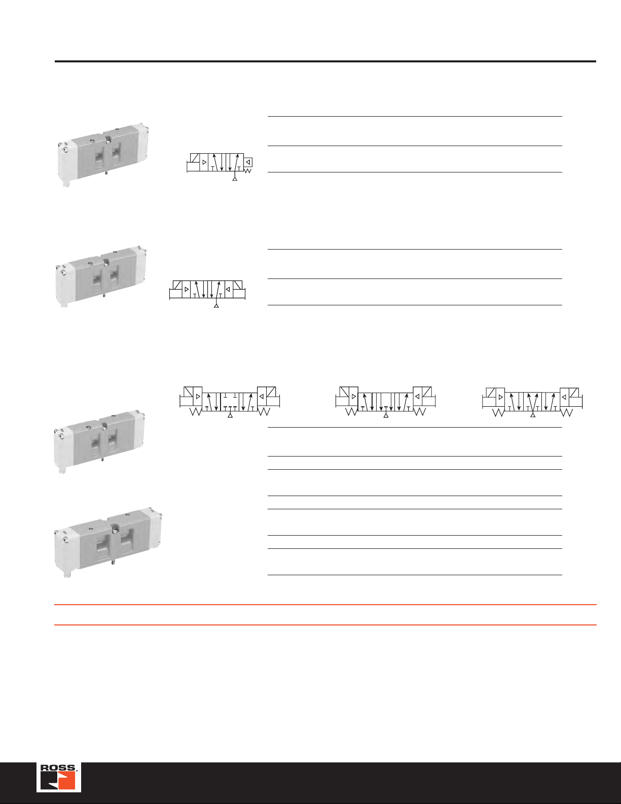
Size 00 (18mm) & Size 0 (26mm )
Open Center
Closed Center
Plug-in, Series W66 (15407-2)
5/2 Valves – Single Solenoid Pilot
ISO Port Valve Model Avg. Dimensions inches (mm) Weight
Size Size Number* C
Series W66, Size 00
Sol. 14
42
1
53
00 1/8 W6676A0401 0.55 4.43 (113) 0.72 (18) 1.98 (50)
0 1/4 W6676A1401 1.1 5.10 (130) 1.02 (26) 1.98 (50)
* Sub-base not included. See page 10-17 for sub-bases, manifolds and
accessories.
5/2 Valves – Double Solenoid Pilot
ISO Port Valve Model Avg. Dimensions inches (mm) Weight
Size Size Number* C
00 1/8 W6676A0407 0.55 4.43 (113) 0.72 (18) 1.98 (50)
0 1/4 W6676A1407 1.1 5.10 (130) 1.02 (26) 1.98 (50)
* Sub-base not included. See page 10-17 for sub-bases, manifolds and
Series W66, Size 00
42
Sol. 14 Sol. 12
1
53
accessories.
5/3 Valves – Double Solenoid Pilot
42
#12#14
53
1
Series W66, Size 00
Series W66, Size 0
ISO Port Valve Model Avg. Dimensions inches (mm) Weight
Size Size Number* C
Closed Center
00 1/8 W6677A0401 0.50 4.43 (113) 0.72 (18) 1.98 (50)
0 1/4 W6677A1401 1.0 5.10 (130) 1.02 (26) 1.98 (50)
00 1/8 W6677A0407 0.50 4.43 (113) 0.72 (18) 1.98 (50)
0 1/4 W6677A1407 1.0 5.10 (130) 1.02 (26) 1.98 (50)
Power Center
00 1/8 W6677A0403 0.50 4.43 (113) 0.72 (18) 1.98 (50)
0 1/4 W6677A1403 1.0 5.10 (130) 1.02 (26) 1.98 (50)
* Sub-base not included. See page 10-17 for sub-bases, manifolds and
accessories.
Length Width Height lb (kg)
V
Length Width Height lb (kg)
V
Power Center
42
#12#14
53
1
Length Width Height lb (kg)
V
Open Center
42
53
1
#12#14
Remote Pressure Control Models Available (2 & 3-Position) – Consult ROSS
STANDARD SPECIFICATIONS (for valves on this page):
Solenoids: Bi-polar, surge suppression (standard), indicator
lights.
Standard V oltages: 1.0, 24 volts DC; 2.0 VA, 120 volts AC.
Flow Media: Filtered air; 5 micron recommended.
Operating Pressure:
Vacuum to 145 psig (9.9 bar).
Minimum Operating Pressure:
2-position : 20 psig (1.37 bar).
3-position: 30 psig (2.07 bar).
Manifolds: Terminal Block Wiring (HA Only).
Collective Wiring: 25-Pin' D-Sub; 19-Pin Round; 16 Point
Terminal Strip; M23, 12-Pin; Isysnet Field Bus.
Construction:
Valve Body: Die Cast Aluminum.
Ens Caps: Polybutylene Terephthalate (PBT).
Fasteners: Zinc Plated Steel.
Coils: Thermoset Plastic.
Port Threads: NPT, BSPP. For BSPP threads add a “D” prefix to
the model number, e.g., DW6677A0401.
Manifolds: Terminal Block Wiring (HA Only).
7www.rosscontrols.com
Page 8
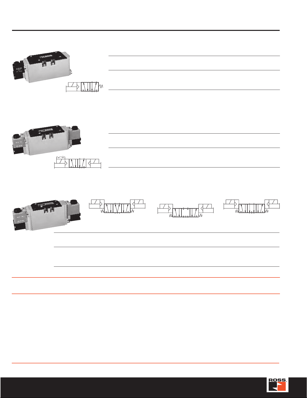
234
Spool and Sleeve Valves for ISO Sub-Bases (5599/II) Series W65
5/2 Valves – Single Solenoid Pilot Controlled, Spring Return
ISO Port Valve Model Avg. Dimensions inches (mm) Weight
Size Size Number* C
1 1/4 - 3/8 W6576A2401 1.0 6.3 (161) 1.6 (41) 2.7 (69) 1.5 (0.7)
14
5
2 3/8 - 1/2 W6576A3401 2.3 7.3 (186) 2.1 (52) 2.8 (71) 2.0 (1.0)
3 1/2 - 3/4 W6576A4401 3.4 8.5 (216) 2.6 (67) 3.1 (78) 3.5 (1.6)
1
* Sub-base not included. See page 11-17 for sub-bases, manifolds and accessories.
5/2 Valves – Double Solenoid Pilot Controlled, Detented
ISO Port Valve Model Avg. Dimensions inches (mm) Weight
Size Size Number* C
1 1/4 - 3/8 W6576A2407 1.0 8.8 (224) 1.6 (41) 2.7 (69) 2.0 (1.0)
14
2
345
1
2 3/8 - 1/2 W6576A3407 2.3 9.0 (228) 2.1 (52) 2.8 (71) 2.5 (1.2)
12
3 1/2 - 3/4 W6576A4407 3.4 10.0 (254) 2.6 (67) 3.1 (78) 4.0 (1.9)
* Sub-base not included. See pages 11-17 for sub-bases, manifolds and accessories.
Length Width Height lb (kg)
V
Length Width Height lb (kg)
V
5/3 Valves – Double Solenoid Pilot Controlled
2
14
4
5
3
1
Power Center
12
14
Closed Center
2
4
12
14
ISO Port Valve Model Number* Avg.
Size Size Power Center Closed Center Open Center CV
1
1/4 - 3/8 W6577A2902 W6577A2401 W6577A2407 1.0 8.8 (224) 1.6 (41) 2.7 (69) 2.0 (1.0)
Dimensions inches (mm) Weight
Length Width Height lb (kg)
2 3/8 - 1/2 W6577A3901 W6577A3401 W6577A3407 2.3 9.0 (228) 2.1 (52) 2.8 (71) 2.5 (1.2)
3 1/2 - 3/4 W6577A4900 W6577A4401 W6577A4407 3.4 10.0 (254) 2.6 (67) 3.1 (78) 4.0 (1.9)
* Sub-base not included. See pages 11-17 for sub-bases, manifolds and accessories.
The W65 Series has a base electrical connector whic h eliminates the need to disconnect wires to remove the valve. This eliminates dr op cords,
simplifies maintenance and connection to Serial Data Communication systems. For more information, refer to Bulletin 379B (form number A10090).
STANDARD SPECIFICATIONS (for valves on this page):
Solenoids: Rated for continuous duty.
Standard V oltages: 100-110 volts, 50 Hz; 100-120 volts, 60
Hz; 24 volts DC; 110 volts DC. For other voltages, consult
ROSS.
Power Consumption: Each solenoid. 6.5 VA holding on 50
or 60 Hz; 3.5 watts on DC (at 10 bar).
Ambient Temperature: 40° to 120°F (4° to 50°C).
Media Temperature: 40° to 175°F (4° to 80°C).
Flow Media: Filtered air; 5 micron recommended.
Standard Inlet Pressure:
Size 1 models: 2-10 bar; Size 2 & 3 models: 1-10 bar.
All sizes also available up to 16 bar.
Pilot Supply: Internal/external supply selected automatically.
Required pressure at least 30 psig (2 bar).
Certification / Approval: CSA
Materials of Construction:
End Caps & Valve Body: Die Cast Aluminum
Fasteners: Zinc Plated Steel
Spool & Sleeve: Stainless Steel
Coils: Thermoset Plastic
234
5
1
Open Center
12
IMPORTANT NOTE: Please read carefully and thoroughly all of the CAUTIONS on the inside back cover.
8 © 2012, ROSS CONTROLS
®
. All Rights Reserved.
Page 9
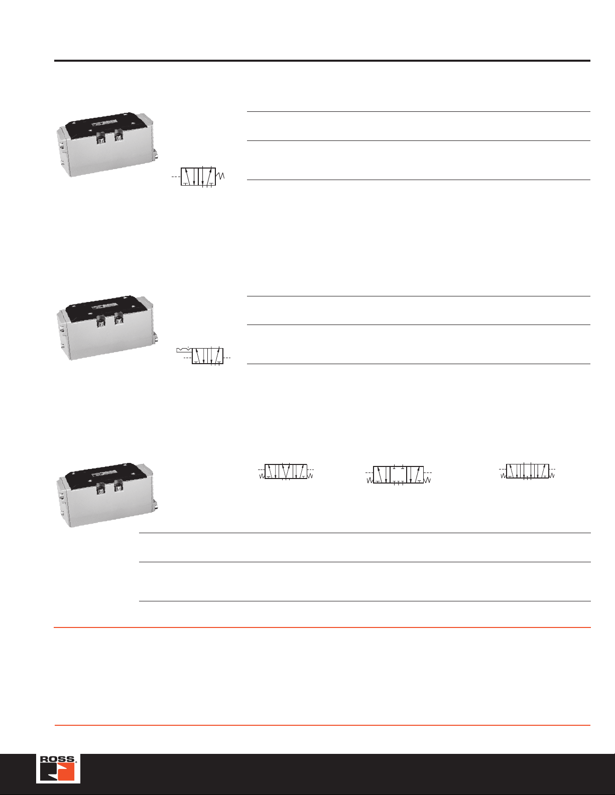
Spool and Sleeve Valves for ISO Sub-Bases (5599/II) Series W65
2
5/2 Valves – Single Pressure Controlled, Spring Return
ISO Port Valve Model Avg. Dimensions inches (mm) Weight
Size Size Number* C
1 1/4 - 3/8 W6556A2411 1.0 4.8 (121) 1.6 (41) 2.7 (69) 0.8 (0.4)
2 3/8 - 1/2 W6556A3411 2.3 5.8 (148) 2.1 (52) 2.8 (71) 1.5 (0.7)
3 1/2 - 3/4 W6556A4411 3.4 7.0 (178) 2.6 (67) 3.1 (78) 3.0 (1.4)
* Sub-base not included. See pages 11-17 for sub-bases, manifolds and accessories.
5/2 Valves – Double Pressure Controlled, Detented
ISO Port Valve Model Avg. Dimensions inches (mm) Weight
Size Size Number* C
1 1/4 - 3/8 W6556A2417 1.0 4.8 (121) 1.6 (41) 2.7 (69) 0.8 (0.4)
2 3/8 - 1/2 W6556A3417 2.3 5.8 (148) 2.1 (52) 2.8 (71) 1.5 (0.7)
3 1/2 - 3/4 W6556A4417 3.4 7.0 (178) 2.6 (67) 3.1 (78) 3.0 (1.4)
* Sub-base not included. See pages 11-17 for sub-bases, manifolds and accessories.
V
V
A B C lb (kg)
A B C lb (kg)
5/3 Valves – Double Pressure Controlled
Power Center
ISO Port Valve Model Number* Avg.
Size Size Power Center Closed Center Open Center CV
1
2 3/8 - 1/2 W6557A3901 W6557A3411 W6557A3417 2.3 5.8 (148) 2.1 (52) 2.8 (71) 1.5 (0.7)
3 1/2 - 3/4 W6557A4900 W6557A4411 W6557A4417 3.4 7.0 (178) 2.6 (67) 3.1 (78) 3.0 (1.4)
* Sub-base not included. See pages 11-17 for sub-bases, manifolds and accessories.
STANDARD SPECIFICATIONS (for valves on this page):
Ambient/Media Temperature: 40° to 175°F (4° to 80°C).
Flow Media: Filtered air; 5 micron recommended.
Standard Inlet Pressure:
Size 1 models: 2-10 bar;
Size 2 & 3 models: 1-10 bar.
All sizes also available up to 16 bar.
1/4 - 3/8 – W6557A2411 W6557A2417 1.0 4.8 (121) 1.6 (41) 2.7 (69) 0.8 (0.4)
14
12
345
1
234
5
1
Closed Center Open Center
Dimensions inches (mm) Weight
A B C lb (kg)
Pilot Supply: Internal/external supply selected automatically.
Required pressure at least 30 psig (2 bar).
Materials of Construction:
End Caps & Valve Body: Die Cast Aluminum
Fasteners: Zinc Plated Steel
Spool & Sleeve: Stainless Steel
1214
IMPORTANT NOTE: Please read carefully and thoroughly all of the CAUTIONS on the inside back cover.
9www.rosscontrols.com
Page 10
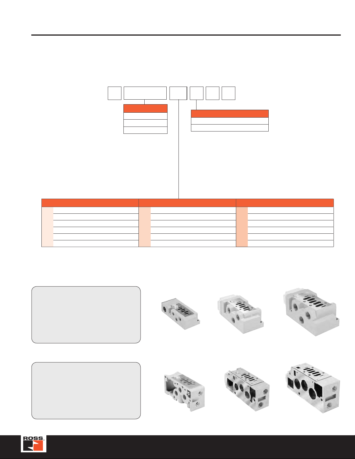
Plug-in, Series W66 (15407-2)
Size 00 & 0 Manifold / Sub-Base Kits
HOW T O ORDER
(Choose your options (in red) to configure your valve model number.)
R PS5511 13 M P
Basic Series
ISO 15407-2 18mm,
Series W66, Size 00
ISO 15407-2 26mm,
Series W66, Size 0
PS5611
PS5511
Mounting Style / Port Size
Series W66, Size 00
Manifold with 1/8 NPT End Ports 51
Manifold with 1/8 BSPP End Port 52
Manifold with 1/8 NPT Bottom / End Port 61
Manifold with 1/8 BSPP Bottom / End Port 62
Series W66, Size 0
Subbase with 1/4 NPT Side Ports 13
Subbase with 1/4 BSPP Side Ports 14
Subbase with 1/4 NPT Bottom / Side Port 23
Subbase with 1/4 BSPP Bottom / Side Port 24
Manifold with 1/4 NPT End Port 53
Manifold with 1/4 BSPP End Port 54
Manifold with 1/4 NPT Bottom / End Port 63
Manifold with 1/4 BSPP Bottom / End Port 64
Enclosures / Lead Length
J* Circuit Board, Single Address
M* Circuit Board, Double Address
Sub-Base Kits
Series W66, Size 0 Sub-Base
10 © 2012, ROSS CONTROLS
Series W66, Size 00 Series
2-Station Manifold
Manifold Kits
®
. All Rights Reserved.
Series W66, Size 0 Series
2-Station Manifold
Page 11
Plug-in, Series W65 (5599-2)
Size 1, 2, & 3 Manifold / Sub-Base Kits
HOW T O ORDER
(Choose your options (in red) to configure your valve model number.)
R PS4011 55 M C P
Basic Series
Size 1 PS4011
Size 2 PS4111
Size 3 PS4211
Note:
When using the Enclosure / Lead Length “J” or “M” option:
12 volts DC - Maximum number of coils is 13
24 volts DC - Maximum number of coils is 21
120 volts AC - Coils limited by the number of pins available in the connector
(25-Pin D-Sub = 24 coils, 19-Pin Brad Harrison = 16, 12-Pin M23 = 8)
240 volts AC - Must use “A” or “C” Option, Lead Wires or Terminal Blocks
Mounting Base Style / Port Size
Sub-base: 3/8 NPT Side Ports 15
Sub-base: 3/8 BSPP Side Ports 16*
Manifold: 3/8 NPT End Ports 55
Manifold: 3/8 NPT End Ports 56*
Size 1
Manifold: 3/8 NPT Bottom / End Port 65
Manifold: 3/8 BSPP Bottom / End Port 66*
* BSPP ISO 1179 Specifications.
† #1 Bottom Port - 1/4".
Sub-base: 1/2 NPT Side Ports 17
Sub-base: 1/2 BSPP Side Ports 18*
Sub-base: 1/2 NPT Bottom / End Port 27
Sub-base: 1/2 BSPP Bottom / End Port 28
Size 2
†
†
Manifold: 1/2 NPT Bottom / End Port 67
Manifold: 1/2 BSPP Bottom / End Port 68*
†
J
†
M
† Not Available with Subbase Kits.
Circuit Board, Single Address
Circuit Board, Double Address
Enclosures / Lead Length
Sub-base: 3/4 NPT Side Ports 19
Sub-base: 3/4 BSPP Side Port 10*
Sub-base: 3/4 NPT Bottom / End Port 29
Sub-base: 3/4 BSPP Bottom / End Port 20
Size 3
Manifold: 3/4 NPT Bottom / End Port 69
Manifold: 3/4 BSPP Bottom / End Port 60*
Sub-Base Kits
Automotive Connectors
Mounted in 1/2" Conduit Port
• 3-Pin-WiredforSingleSolenoid
• 4-Pin/5-Pin-WiredforDoubleSolenoid
Manifold Kits
Automotive Connectors
Mounted in Individual Manifold Conduit Cover
• 3-Pin - Wired for Single Solenoid
• 4-Pin / 5-Pin - Wired for Double Solenoid
Size 1
Size 1
Size 2 Size 3
Size 2 Size 3
11www.rosscontrols.com
Page 12
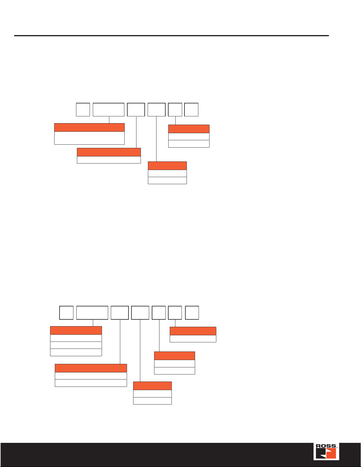
End Plate Kits, Series W66 & W65
Series W66
Size 00 & 0 End Plate Kits
HOW T O ORDER
(Choose your options (in red) to configure your valve model number.)
R PS56 20 T1 0 P
Basic Series
ISO 15407, Size 00 (18mm) &
Size 0 (26mm)
End Plate Kit Type
End Plate, Collective Wiring 20
PS56
Series W65
Size 1, 2, & 3 End Plate Kits
HOW T O ORDER
(Choose your options (in red) to configure your valve model number.)
0 NPT
1
Options
T1 16 Outputs
T2 32 Outputs
Thread Type
BSPP “G”
R PS40 20 T1 0 C P
Basic Series
ISO 5599, Size 1 PS40
ISO 5599, Size 2 PS41
ISO 5599, Size 3 PS42
End Plate Kit Type
End Plate, Collective Wiring 20
End Plate, Non-Collective Wiring 31
T1 16 Outputs
T2 32 Outputs
0 NPT
1
Options
12 © 2012, ROSS CONTROLS
Engineering Level
C Current
Thread Type
BSPP “G”
®
. All Rights Reserved.
Page 13
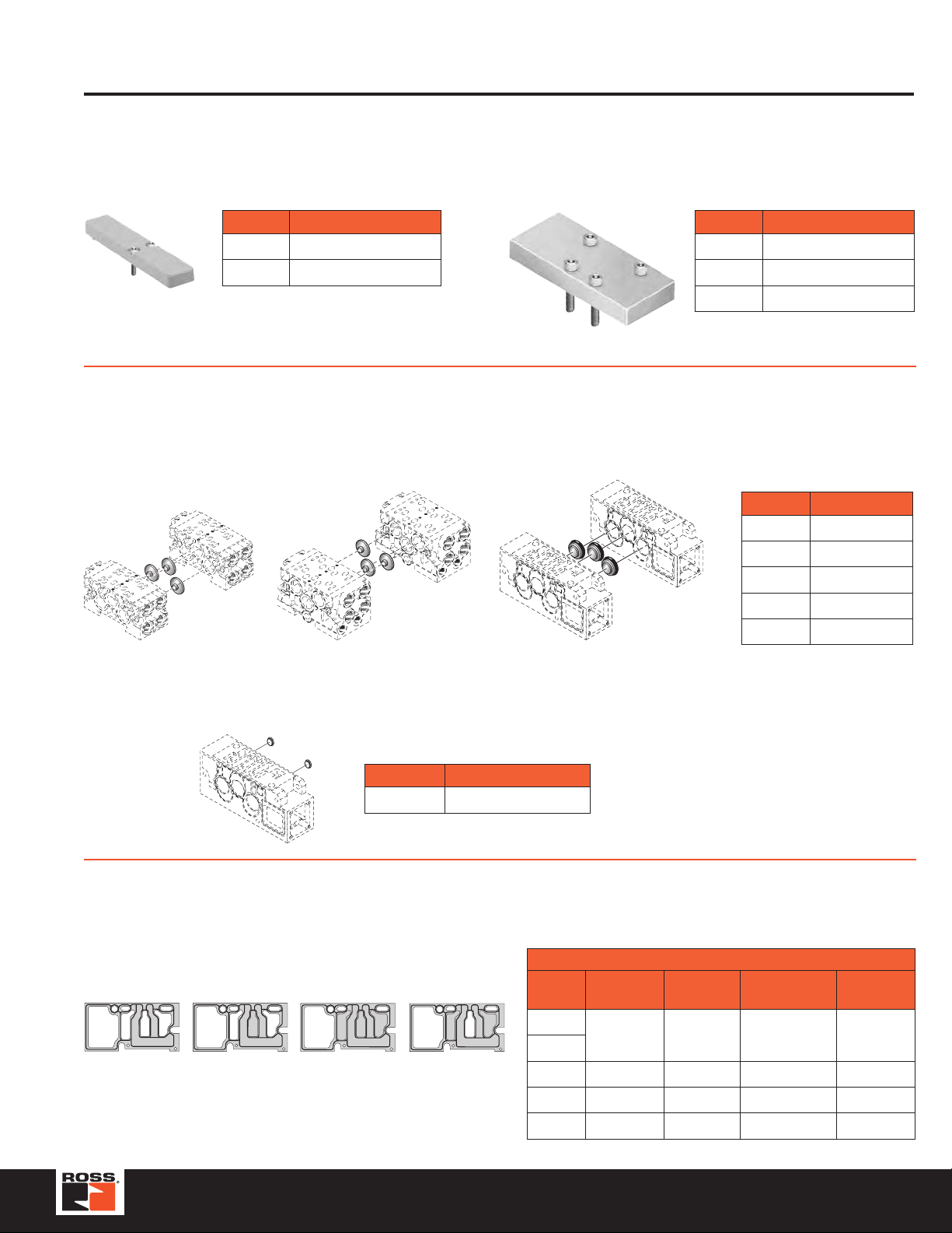
Blank Stations, Port Isolation , Gaskets
Blank Station Kits
Accessories
Size Kit Number 15407-2
RPS5634P
RPS5534P
15407-2
Size 00
Size 0
Kit includes: Blank Station Plate, Gasket,
and Mounting Bolts.
Manifold Port Isolation Kits
Main Galley (1, 3, 5)
2
4
2
4
Size 00
Main Galley
Size 0
Main Galley
5599
Size1, 2, 3
Main Galley
Size Kit Number 5599
Size 1
Size 2
Size 3
Kit includes: Blank Station Plate, Gasket,
and Mounting Bolts.
RPS4034CP
RPS4134CP
RPS4234CP
Size Kit Number
Size 00
Size 0
Size 1
Size 2
Size 3
Kit includes: Plugs with O-rings.
RD02BD0
RD01BD0
RPS4032CP
RPS4132CP
RPS4232CP
Pilot Galley
Size Kit Number
Size1, 2, 3
Pilot Galley
1, 2, & 3
Kit includes: Plugs with O-rings.
Manifold to Manifold Gasket Kits
RPS561AP RPS561CP RPS561DPRPS561BP
RPS4033CP
Size Standard
Size 00
Size 0
Size 1
Size 2
Size 3
15407-2
Blocked
#1 Port
RPS561AP RPS561BP RPS561CP RPS561DP
RPS4013P — — —
RPS4113P — — —
RPS4213P — — —
Blocked
#1, 3, 5 Ports
Blocked
#3, 5 Ports
13www.rosscontrols.com
Page 14
Accessories
Size 00 & 0
HOW T O ORDER
(Choose your options (in red) to configure your valve model number.)
R PS5637 1 6 6 P
Basic Series
Size 00 15407-2, 18mm PS5638
Size 0 15407-2, 26mm PS5538
Regulator Function
Common Pressure Regulator 1
Independent Pressure Regulator 2
#4 Port Regulator / Gauge*
2 2-60 PSIG w/o Gauge
3 5-125 PSIG w/o Gauge
5 2-60 PSIG w/Gauge
6 5-125 PSIG w/Gauge
* For Common Pressure Regulator Option, Regulator Gauge callout must
be the same number for both Port #4 and Port #2. (Example: 166)
* For Common Pressure Regulator Option, Regulator
Gauge callout must be the same number for both
Port #4 and Port #2. (Example: 166)
Size 1, 2 , & 3
HOW T O ORDER
(Choose your options (in red) to configure your valve model number.)
#2 Port Regulator / Gauge*
2 2-60 PSIG w/o Gauge
3 5-125 PSIG w/o Gauge
5 2-60 PSIG w/Gauge
6 5-125 PSIG w/Gauge
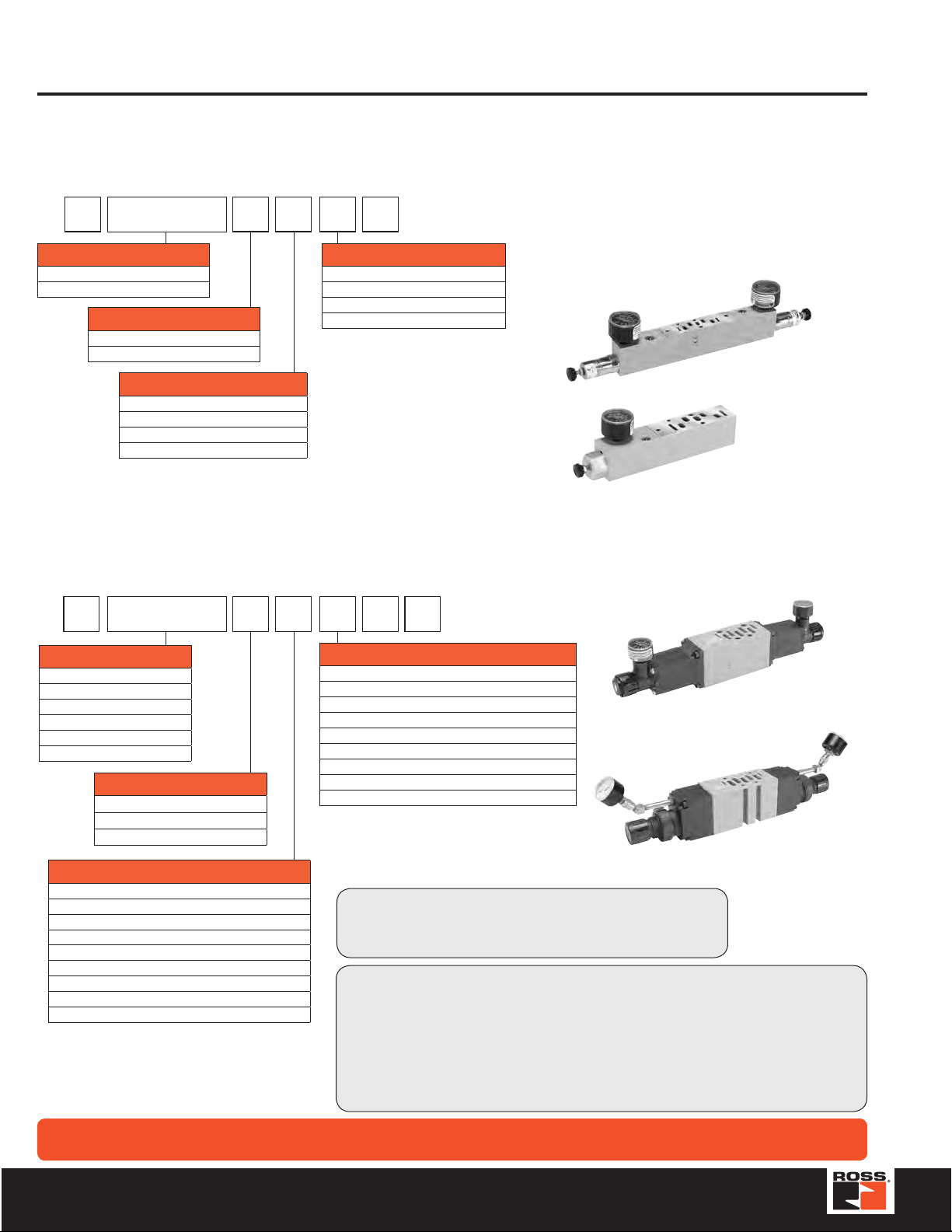
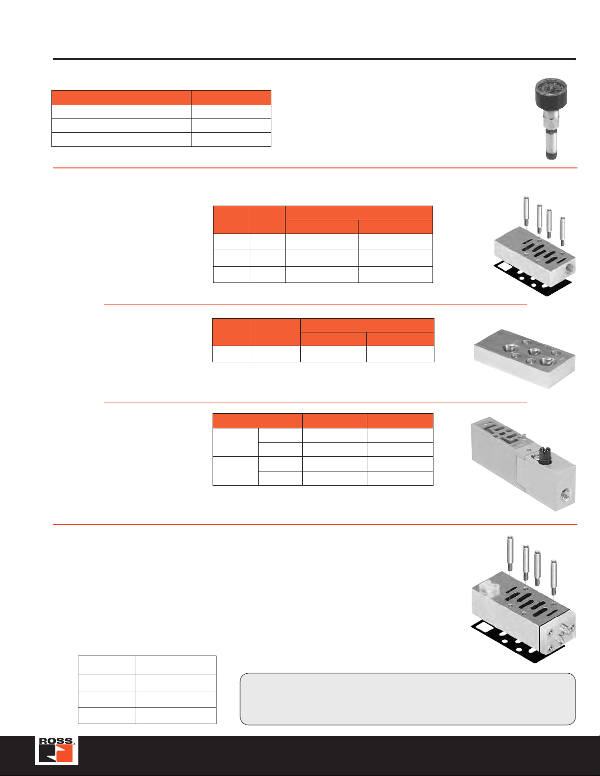
Interposed Regulators
Features:
• Remote Air Pilot Operated for hard-to-reach pressure
control
• Unregulated Pilot Pressure to valve for consistent
valve shifting reg ardl ess of pre ssure ad just ment
Size 00 - 18mm
(Dual Interposed Regulator Shown)
Size 0 - 26mm
(Single Interposed Regulator Shown)
R PS4037 1 6 6 C P
Basic Series
Size 1 5599-1 PS4037
Size 1 5599-2 PS4038
Size 2 5599-1 PS4137
Size 2 5599-1 PS4138
Size 3 5599-1 PS4237
Size 3 5599-1 PS4238
Regulator Function
Common Pressure Regulator 1
Independent Pressure Regulator 2
Selector Regulator 3
#4 Port Regulator / Gauge*
0** Line By-Pass Plate
1 1-30 PSIG w/o Gauge
2 2-60 PSIG w/o Gauge
3 5-125 PSIG w/o Gauge
4 1-30 PSIG w/Gauge
5 2-60 PSIG w/Gauge
6 5-125 PSIG w/Gauge
C Air Pilot w/60 PSIG Gauge
D Air Pilot w/160 PSIG Gauge
* For Common Pressure Regulator Option, Regulator Gauge callout must
be the same number for both Port #4 and Port #2. (Example: 166)
** Pressure Line By-Pass Option can only be used with Independent and
Selector Regulators (Option 2 & 3 in Interposed Block Function).
Ordering Components
• Manifold or Subbase Kit required
• Interposed Regulator Kit configured for Internal Pilot as standard
• Order valve as External Pilot
How to Configure Interposed Regulator / Valve Combinations
Internal Pilot Configuration - Pressure in Base Port 1 feeds regulator configured for
Internal Pilot which feeds valve configured for External Pilot.
External Pilot Configuration - Size 1, Size 2, Size 3
An External Pilot pressure in Port 12 or 14 of the base feeds thru the Interposed
Regulator 12 or 14 galley directly to the 12/14 pilot of the valve.
This configuration takes an External Pilot from the 12 port of the base and passes it thru
the regulator to feed the 12 galley of the valve.
#2 Port Regulator / Gauge*
Size 1
(Dual Interposed Regulator Shown)
Size 2
(Dual Interposed Regulator Shown)
WARNING
Double interposed regulators will reverse output ports, the 12 solenoid will pressurize the 4 port, the 14 solenoid will
pressurize the 2 port which may cause unexpected, potentially dangerous cylinder movement at valve pressurization.
14 © 2012, ROSS CONTROLS
®
. All Rights Reserved.
Page 15
Gauge Adapter Kit
Description Part Number
Gauge Kit RPS5651160P
1/8" Female to 1/8" Female Coupling R207P-2*
1/8" Male to 1/8" Male Long Nipple RVS215PNL-2-15*
* Included in Gauge Kit RPS5651160P
Included with all Size 00 Regulators. Both kits are
required on all Size 0 & 00 Regulators when the
Regulator is on the last Station on the Right (14) End.
Remote Pilot Access Plates, Exhaust Modules, Air Supply Bases
Accessories
Remote Pilot
Access Plate Kits
Size 1
Auxiliary
Access Plate Kits
Interposed Supply &
Exhaust Modules
Size
Size 1 1/8" RPS401500CP RPS401501CP
Size 2 1/8" RPS411500CP RPS411501CP
Size 3 1/8" RPS421500CP RPS421501CP
Kit includes: Pilot Port Access Plate, Gasket and Mounting Studs.
Size Port Size
Size 1 1/4" & 3/8" RPS403000CP RPS403001CP
Kit includes: Pilot Port Access Plate, Gasket and Mounting Screws.
•UsedonSize1ManifoldstoprovideauxiliaryaccesstoPorts1,3&5.
•Port1:1/4",Ports3&5:3/8".
Size 00
(15407-2)
Size 0
(15407-2)
Quantity 1
•UsedonSize00&Size0valvestoprovideapressureorexhaust
path to individual valves.
Port
Size
Valve Size NPT BSPP “G”
Supply RPS561600P RPS561601P
Exhaust RPS561700P RPS561701P
Supply RPS551600P RPS551601P
Exhaust RPS551700P RPS551701P
Kit Number
NPT BSPP “G”
Kit Number
NPT BSPP “G”
Height: .72 Inch
5599-1 Shown
15407-2 Shown
Interposed Flow Controls
Features:
• Bothadjustmentscrewsarelocatedonthe12endoftheunit.
•
Interposed Flow Contr ol mounts with its own studs, w hich means the valve uses
standard bol ts for mo unti ng.
• InterposedFlowControlisnottobeused as a shutoffdevice andisnotbubble
tight when need le s are fully tur ne d d own.
Valve Size Plug-In 5599-2
Size 1 RPS4035CP
Size 2 RPS4135CP
Size 3 RPS4235CP
A Interposed Flow Control and Common Port Interposed Regulator may be
sandwiched together on a manifold or subbase. The Interposed Flow Control
MUST be located between the manifold/subbase and the Common Port
Interposed Regulator.
Plug-In 5599-2
Size 2 Shown
15www.rosscontrols.com
Page 16

Service & Repair Kits
Series W65 Replacement Pilot
Assembly & Coil
Description Model Number
Pilot Assembly 1149C79
Coil 334B33
Specify Voltage and Hz when ordering.
Manifold Hardware Kits
Valve Size Kit Number
Size 00 RPS5612P
Size 0 RPS5512P
Size 1 RPS4012P
Size 2 RPS4112P
Size 3 RPS4212P
Quantity 12
Valve Bolt Kits
Valve Size Kit Number
Size 00 RPS5687P
Size 0 RPS5587P
Quantity 12
Manifold to Manifold Gasket Kits
15407-2
Size Standard
Size 00
Size 0
Size 1 RPS4013P — — —
Size 2 RPS4113P — — —
Size 3 RPS4213P — — —
RPS561AP RPS561CP RPS561DPRPS561BP
RPS561AP RPS561BP RPS561CP RPS561DP
Blocked
#1 Port
Blocked
#1, 3, 5 Ports
Blocked
#3, 5 Ports
Regulator & Flow Control Mounting Studs
Type Size 00 Size 0
Flow Control
Regulator
Type Size 1 Size 2 Size 3
Flow Control RPS4036P RPS4136P RPS4236P
Regulator RPS4040P RPS4140P RPS4240P
Quantity 12
RPS5636P RPS5536P
RPS5636P RPS5536P
Regulator Kits
Valve Size Kit Number
Size 1 RPS4039P
Size 2 & 3 RPS4139P
Pilot Select Gasket Kits
Valve Size Kit Number
Size 00 RPS5605P
Size 0 RPS5505P
Quantity 10
Indicates External Pilot
Size 00 Shown
Indicates Internal Pilot
Valve to Base Gasket Kits
Valve Size Standard
Size 00 RPS5605P*
Size 0 RPS5505P*
Size 1 797B11
Size 2 828B11
Size 3 858B11
Quantity 1, * Quantity 10.
Regulator Gauge Kits – Size 1, 2 & 3
Gauge Type Kit Number
3/4" Face Air - Standard
0-60 PSIG RPS4051060BP
0-160 PSIG RPS4051160BP
1-1/2" Face Air - Large*
0-60 PSIG RPS4053060BP
0-160 PSIG RPS4053160BP
1-1/2" Face Liquid*
0-160 PSIG RPS4052160BP
* Includes brass pipe fitting extensions
Quantity 1
Body Service Kits
Valve
Size
Size 00
Size 0
Size 1 1422K77 1423K77 1424K77 1425K77 1424K77
Size 2 1467K77 1468K77 1469K77 1470K77 1469K77
Size 3 1471K77 1472K77 1473K77 1474K77 1473K77
Kit Includes: Spool assembly with seals, all piston seals, return spring, pilot selector
gasket, coil to end cap gasket.
Quantity 1
2
Position
Single
RPS5601P RPS5601P RPS5602P RPS5603P RPS5604P
RPS5501P RPS5501P RPS5502P RPS5503P RPS5504P
2
Position
Double
Closed
Center
3-Position
Open
Center
Power
Center
16 © 2012, ROSS CONTROLS
®
. All Rights Reserved.
Page 17

Service & Repair Kits
Regulator Conversion Kits Regulator Spring Range Kits
Valve
Size
Size 1 RPS4045BP RPS4047BP RPS4048BP
Size 2
Size 3
Quantity 1
Manual Bonnet
Assembly
(w/o Spring)
RPS4145BP RPS4147BP RPS4148BP
Air Pilot
Bonnet
Assembly
Independent
By-Pass
Plate
Technical Information
Temperature Rating
Size 00, 0, 1, 2, & 3
-15°C to 49°C (5°F to 120°F) Ambient.
Flow Rating (Cv)
Valve Size Port Size 2-Position 3-Position
Size 00 1/8" 0.55 0.50
Size 0 1/4" 1.1 1.0
Size 1 3/8" 1.0 1.0
Size 2 1/2" 2.3 2.3
Size 3 3/4" 3.4 3.4
Cv tested per ANSI / (NFPA) T3.21.3
Spring Range Size 1 Size 2 & 3
0 to 30 PSIG RPS4050030P RPS4150030BP
2 to 60 PSIG RPS4050060P RPS4150060BP
5 to125 PSIG RPS4050125P RPS4150125BP
Quantity 1
Response Time** (ms)
Valve
Size
Port
Size
Single Solenoid 2-Position - Air Return / Spring Assist
Size 00 1/8" 28 30 141 154
Size 0 1/4" 24 26 77 124
†
Size 1
Size 2
Size 3
##
Size 00 (12), Size 0 (25)
** With 100 PSIG supply, time (ms) required to fill from 0 to 90 PSIG and Exhaust
from 100 PSIG to 10 PSIG measured from the instant of energizing or deenergizing 24VDC solenoid.
† For valve response time information for Size 1, 2, & 3 valves, see ROSS Bulletin
379B - form # A10090.
Tested per ANSI / (NFPA) T3.21.8
3/8" — — — —
†
1/2" — — — —
†
3/4" — — — —
0 Cu. In. Chamber ## Cu. In. Chamber
Fill Exhaust Fill Exhaust
Operating Pressure
Size 00, 0, 1, 2, & 3
Maximum: 145 PSIG (1000 kPa)
Minimum:
Internal Pilot
Single Solenoid - 2-Position
Double Solenoid- 2-Position
Single Remote Pilot - 2-Position ** Vacuum Vacuum
Double Remote Pilot - 2-Position** Vacuum Vacuum
Double Solenoid - 3-Position (CC, OC, PC)
Double Remote Pilot - 3-Position** (CC, OC, PC) Vacuum Vacuum
Single Solenoid Pilot - 2-Position
Air Return / Spring Assist
Single Remote Pilot - 2-Position**
Air Return / Spring Assist
PSIG (Min. kPa)
Series W66, Size 00
30
(207)
35
(241)
30
(207)
External Pilot * * *
All Functions Vacuum Vacuum
* External Pilot Pressure / Remote Pilot Supply - 45-145 PSIG (310-1000 kPa).
** Must be equal to or greater than operating pressure.
PSIG (Min. kPa)
Series W66, Size 0
25
(173)
35
(241)
30
(207)
See pages 13 & 14 for
Sizes 1, 2 & 3
17www.rosscontrols.com
Page 18

TURCK Modular Industrial I/O System BL 67
The BL67 Solution
BL67 combines all the flexibility of an in-the-cabinet PLC I/O
system with modularity, ruggedness and connectorization.
BL67 complements the AIM™, BL20 and piconet
families to meet the needs of unique applications, such as small
machine or conveyor systems requiring IP 67 protection.
The BL67 Concept
The BL67 modular concept is a very flexible approach to
connectorized I/O. The gateway, base and electronic modules
provide many benefits to the user.
• The gateway provides comm unication betw een the fieldbus
and I/O modules; modules are not dependent on the fieldb us
protocol.
• DIN-rail or frame mountable base modules are av ailable with
eurofast
®
(M12), minifast® (7/8-16UN), M23 and picofast®
(M8) connectors.
• Electronic modules are hot swappable.
• Power distribution module (24 volts DC) supplies the
connected I/O signals.
BL67’s openness, flexibility, connectorization, compact
housing and ruggedness provide a viable alternative to inthe-cabinet I/O.
Maximum Size of a BL67 Station
BL67 stations consist of a gateway and a maximum of 32
modules (equivalent to 1 m station length). Some high-tech and
analog I/O modules may consume or produce large amounts
of data, and therefore may limit the number of modules that
may be used per system. It is highly recommended that the I/
Oassistant software is used when planning and commissioning
BL67 systems. This prog ram allows you to b uild the BL67 node
on your computer and verify that all restrictions with regard
to power and size are met. The free I/O assistant software is
available for download from www.turck.com.
Addressing
As a node on a network, BL67 stations are addressed
dependent on the network system being used. Each network
gateway has a set of rotary switches used to set the address
for the node. DeviceNet™ and CANopen gateways may be
addressed between 0 and 63 via two switches (one f or the 10’s
digit and one for the 1’ s digit). For e xample, to set the address
to 37 you would set the 10’s switch to 3 and the 1’s switch to
7. The third switch on the gateway may be used to set the
communication rate of the network interface. PROFIBUS
gateways may be set from 1 to 125 by using three switches
(one for the 100’s, one for the 10’s and one for the 1’s).
Ethernet gateways allow different addressing schemes
depending on the Ethernet addressing method being used
in the overall system. Dynamic addressing schemes include
BootP and DHCP, while hard-coding a static address is also
allowed.
®
product
®
-DP
BL67 Power Distribution
Power Overview
The power supply for a BL67 station is fed via the power
connector on the PROFIBUS
network on the DeviceNet™ gateway. Power feeder modules
can be added to the system at any point to provide a fresh
isolated supply of power to all I/O connected to its right.
Internal Power Consumption via Module Bus
The amount of BL67 modules that may be supplied via the
internal module bus depends on the respective nominal current
IMB of the individual modules on the module bus. The sum of
the nominal current inputs of the connected BL67 module must
not exceed 1.5 A. If the I/O assistant software is used, an error
message is generated automatically via the <Station - Verify>
as soon as the system supply via the module bus is no longer
sufficiently guaranteed.
Module
BL67-GW-DPV1 – ≤150 mA
BL67-GW-DN – ≤100 mA
BL67-PF-24VDC ≤30 mA ≤9 mA
BL67-4DI-P ≤30 mA ≤9 mA ≤40 mA
BL67-8DI-P ≤30 mA ≤9 mA ≤40 mA
BL67-4DO-0.5A-P ≤30 mA ≤9 mA ≤100 mA
BL67-4DO-2A-P ≤30 mA ≤9 mA ≤100 mA
BL67-8DO-0.5A-P ≤30 mA ≤9 mA ≤100 mA
BL67-2AI-V ≤35 mA ≤10 mA ≤12 mA
BL67-2AI-I ≤35 mA ≤10 mA ≤12 mA
BL67-2AI-TC ≤35 mA ≤10 mA ≤30 mA
BL67-2AI-PT ≤45 mA ≤13 mA ≤45 mA
BL67-2AO-I ≤40 mA ≤12 mA ≤50 mA
BL67-2AO-V ≤60 mA ≤17 mA ≤50 mA
BL67-1RS232 ≤100 mA ≤28 mA ≤50 mA
BL67-8XSG-PD ≤30 mA ≤9 mA ≤100 mA
BL67-1SSI ≤50 mA ≤15 mA ≤50 mA
BL67-4DI-PD ≤30 mA ≤9 mA
BL67-8DI-PD ≤30 mA ≤9 mA ≤100 mA
To calculate current draw on DeviceNet: Add IMB(24) for all
modules. Then add VI and VO f or electronic modules to the left
of the first power feed module. Next, add the current draw of
the I/O devices.
To calculate current draw on PROFIBUS gateway power
connector for VI: Add IMB for all modules. Then add VI current
for all modules to the left of the first power feed module. Next,
add the current draw of the input devices.
For V O , add the VO current for all modules to the left of the first
power feed module. Next, add the current draw of the output
devices.
VMB = Module bus power
VI = Input power
VO = Output power
IMB = Module bus current
IMB(24) = Effective current dra w from gateway at 24 v olts DC supply
Nominal 1
Current
at 5 V I
®
gateway or directly from the
MB(24)
Nominal 3
Current
from V
Effective Draw 2
from Gateway at
24 VDC I
MB
Nominal 4
I
≤100 mA
Current
from V
O
18 © 2012, ROSS CONTROLS
®
. All Rights Reserved.
Page 19

TURCK Modular Industrial I/O System BL 67
Applying Power to BL67
PROFIBUS® , Ethernet and CANopen System
System Power
Isolation
Field Power
< 1.5A
I
MB(5V)
< 4A
I
I
(protected)
IO < 8A
V
MB(5V)
V
MB(24V)IMB(24V)
VOV
I
VI, VO, V
V
MB
V
V
4A
from Power on Gateway
MB
I
I
I
O
= Module Bus Power
= Input Power
I
= Output Power
O
I
MB(5V)
4A
VOV
I
Isolation of Field Power VI, V
I
I
I
O
O
A power feeder module provides
a new isolated segment for all
modules to its right.
System Power
Field Power
I
< 1.5A
MB(5V)
I
< 4A
I
(protected)
IO < 8A
V
MB(5V)
V
MB(24V)IMB(24V)
VOV
I
VI, VO, V
V
MB
V
I
V
O
4A
from DeviceNet™
MB
= Module Bus Power
= Input Power
= Output Power
TM
System
I
MB(5V)
DeviceNet
Isolation
4A
I
I
I
O
VOV
I
Isolation of Field Power VI’ V
I
I
I
O
O
A power feeder module provides
a new isolated segment for all
modules to its right.
19www.rosscontrols.com
Page 20

TURCK Modular Industrial I/O System BL 67
Environmental Conditions
Intended Application Environments
• BL67 does not need an enclosure
• Mount directly on machine or conveyor
•
Rugged design provides protection against dirt, dust and
liquids
Not intended for These Environments
• Continuous submersion
• 100 percent humidity
• High pressure washdown
Note:
For higher le vels of protection consider fully potted AIM stations .
BL 67 Selection Guide
General Environmental
Potential isolation Via optocoupler
Operating temperature 32° to +131°F (0° to +55°C)
Storage temperature -13° to +185°F (-25° to +85°C)
Relative humidity 5 to 95% (indoor), noncondensing
Vibration 1.0 g 5-10 Hz
Shock 15 g
Protection class
Electromagnetic
compatibility (EMC)
Housing material PC-V0 (Lexan), Nickel plated brass
Approvals CE
IP 67, NEMA 1, 3, 4, 12, 13
According to EN 61131-2
UL (pending)
CSA (pending)
Gateways Higher Level System Pages
DeviceNet
Ethernet
PROFIBUS-DP
CANopen
21
22, 23
24
25, 26
Modules Type I/O Direction Pages
Input 33-34, 36
Discrete
Analog
Serial
Output 29-31, 36
Input & Output 35
Input 40
Output 42
Input & Output 38-39
20 © 2012, ROSS CONTROLS
Power Feed
Base Modules
Accessories
®
. All Rights Reserved.
43
44
45
Page 21

TURCK Modular Industrial I/O System BL 67
Modular I/O • Fieldbus Independent Configuration • IP 67 Protection • Various I/O Styles
DeviceNet Gateway
Electrical: • Operating Current: <600 mA from V
BL67-GW-DN
MB
• Supply Current: <8 A to I/O (from DeviceNet)
• Backplane Current: <1.5 A (from DeviceNet)
Mechanical: • Operating Temperature: 0 to +55°C (+32 to +131°F)
• Protection: IP 67
• Vibration: 5 g @ 10-500 Hz
Material: • Housing: PC-V0 (Lexan)
Diagnostics (Logical)
• Diagnostic information available through the DeviceNet I/O map
Diagnostics (Physical)
• LEDs to indicate status of DeviceNet and Module Bus communication
3.051 (77.5)
Service
Port and
Address
Switches
(91.0)
5.709
(145.0)
3.583
DeviceNet
2.913 (74.0)
BL67
GW-DN
GW
VCC
MNS
IO
Diagnostic
VO
VI
IO
LEDs
DeviceNet
Connector
DeviceNet
Connector
DeviceNet
1.260 (32.0)
DeviceNet minifast
®
Pinouts
Male Female
1 = Shield
2 = V+
3 = V4 = CAN_H
5 = CAN_L
3
2
2
4
1
5
1
3
4
5
5-Pin 5-Pin
Note: Power feeding modules may be used for I/O current supply to prevent overloading the DeviceNet power supply.
21www.rosscontrols.com
Page 22

TURCK Modular Industrial I/O System BL 67
3.051 (77.5)
Ethernet Pinout
Modular I/O • Fieldbus Independent Configuration • IP 67 Protection • Various I/O Styles
ModBus TCP/IP
Ethernet Gateways
Ethernet IP
Ethernet Gateways
Electrical: • Operating Current: <600 mA from V
BL67-GW-EN
BL67-PG-EN
BL67-GW-EN-IP
BL67-PG-EN-IP
MB
• Input Supply Current: <4 A (from VI)
• Output Supply Current: <8 A (from VO)
• Backplane Current: <1.5 A (from V
MB)
Mechanical: • Operating Temperature: -12 to +55°C (-13 to +131°F)
• Protection: IP 67
• Vibration: 5 g @ 10-500 Hz
Material: • Housing: PC-V0 (Lexan)
Diagnostics (Logical)
• Diagnostic information available through the DeviceNet I/O map
Diagnostics (Physical)
• LEDs to indicate status of DeviceNet and Module Bus communication
Programmability
• PG in part number designates a programmable gateway
• Progammable according to IEC 61131.3 using CodeSys
(includes ladder logic)
• Use CodeSys to create logic programs to control local I/O
5.709
(145.0)
3.583
(91.0)
Service
Port and
Address
Switches
2.913 (74.0)
ETHERNET
POWER
BL67
GW-EN
VCC
LNK/ACT
GW
VO
VI
MS
1.260
(32.0)
Female
4
1 = TD+
2 = RD+
3
1
3 = TD-
IO
4 = RD-
2
4-Pin
Diagnostic
LEDs
Ethernet
Connector
5-pin minifast ® Power Pinout
Male
Power
Connector
1 = Gnd
2 = Gnd
3 = PE
4 = V
I
5 = V
O
3
2
4
5
1
5-Pin
22 © 2012, ROSS CONTROLS
®
. All Rights Reserved.
Page 23

TURCK Modular Industrial I/O System BL 67
3.051 (77.5)
2.913 (74.0)
Pinout
Modular I/O • Fieldbus Independent Configuration • IP 67 Protection • Various I/O Styles
Profinet
Ethernet Gateways
BL67-GW-EN-PN
Electrical:
• Operating Current: <600 mA from V
MB
• Input Supply Current: <4 A (from VI)
• Output Supply Current: <8 A (from VO)
• Backplane Current: <1.5 A (from V
MB)
Mechanical: • Operating Temperature: -12 to +55°C (-13 to +131°F)
• Protection: IP 67
• Vibration: 5 g @ 10-500 Hz
Material: • Housing: PC-V0 (Lexan)
Diagnostics (Logical)
• Diagnostic information available through the DeviceNet I/O map
Diagnostics (Physical)
• LEDs to indicate status of DeviceNet and Module Bus communication
Service
Port and
Address
Switches
3.583
(91.0)
5.709
(145.0)
ETHERNET
BL67
GW-EN
GW
VCC
LNK/ACT
VO
MS
IO
Diagnostic
LEDs
VI
Ethernet
Connector
1 = TD+
2 = RD+
3 = TD4 = RD-
Ethernet Pinout
Female
4
3
2
4-Pin
Power
Connector
POWER
1.260
(32.0)
5-pin minifast
®
Power
Male
1 = Gnd
2 = Gnd
1
3 = PE
4 = V
5 = V
I
O
3
2
4
5
1
5-Pin
23www.rosscontrols.com
Page 24

2.913 (74.0)
1 = Gnd
2 = Gnd
TURCK Modular Industrial I/O System BL 67
Modular I/O • Fieldbus Independent Configuration • IP 67 Protection • Various I/O Styles
PROFIBUS-DP Gateway
Electrical: • Operating Current: <50 mA from V
• Supply Current: <10 A to I/O (from V
• Backplane Current: <1.5 A (from V
BL67-PG-DP
I
)
I and VO
I)
Mechanical: • Operating Temperature: -25 to +55°C (+32 to +131°F)
BL67-GW-DPV1
• Protection: IP 67
• Vibration: 5 g @ 10-500 Hz
Material: • Housing: PC-V0 (Lexan)
Diagnostics (Logical)
• Diagnostic information available through the DeviceNet I/O map
Diagnostics (Physical)
• LEDs to indicate status of DeviceNet and Module Bus communication
Programmability
• PG in part number designates a programmable gateway
• Progammable according to IEC 61131.3 using CodeSys (includes ladder logic)
• Use CodeSys to create logic programs to control local I/O
3.051 (77.5)
Service
Port and
Address
Switches
3.583
(91.0)
5.709
(145.0)
PROFIBUS eurofast ® Pinouts
DP OUT
DP IN
POWER
Male Female
5
1
4
3
2
5-Pin 5-Pin
4
3
5
1
2
1 = 5 VDC*
2 = BUS _A
3 = Gnd
4 = BUS_B
5 = Shield
* Female connector only
Note: Power feeding modules may be used for I/O current supply to prevent overloading the DeviceNet power supply.
BL67 IO
GW-DP
GW
VCC
VO
VI
DIA
BUS
1.260
(32.0)
Diagnostic
LEDs
Profibus-DP
Connector
Power
Connector
minifast ® Power Pinouts
Male
3
4
5
5-Pin
2
3 = PE
4 = V
1
5 = V
I
O
24 © 2012, ROSS CONTROLS
®
. All Rights Reserved.
Page 25

TURCK Modular Industrial I/O System BL 67
3.051 (77.5)
2.913 (74.0)
Modular I/O • Fieldbus Independent Configuration • IP 67 Protection • Various I/O Styles
CANopen Gateway
Electrical: • Operating Current: <600 mA from V
BL67-GW-CO
MB
• Supply Current: <8 A to I/O (from DeviceNet)
• Backplane Current: <1.5 A (from DeviceNet)
Mechanical: • Operating Temperature: -25 to +55°C (+32 to +131°F)
• Protection: IP 67
• Vibration: 5 g @ 10-500 Hz
Material: • Housing: PC-V0 (Lexan)
Diagnostics (Logical)
• Diagnostic information available through the DeviceNet I/O map
Diagnostics (Physical)
• LEDs to indicate status of DeviceNet and Module Bus communication
Service
Port and
Address
3.583
(91.0)
5.709
(145.0)
Switches
BL67
GW-CO
GW
VCC
VO
Bus
Error
IO
Diagnostic
LEDs
VI
CANopen
Connector
Power
Connector
1
CANopen eurofast ®Pinouts
Male Female
5
4
3
2
5-Pin 5-Pin
4
3
2
5
1
1 = Shield
2 = V+
3 = V-
4 = CAN_H
5 = CAN_L
* Female connector only
POWER
1.260
(32.0)
minifast ® Power Pinouts
Male
3
2
4
5
5-Pin
1
1 = Gnd
2 = Gnd
3 = PE
4 = V
I
5 = V
O
Note: Power feeding modules may be used for I/O current supply to prevent overloading the DeviceNet power supply.
25www.rosscontrols.com
Page 26

TURCK Modular Industrial I/O System BL 67
2.913 (74.0)
55
Modular I/O • Fieldbus Independent Configuration • IP 67 Protection • Various I/O Styles
CANopen Gateway
Electrical: • Operating Current: <600 mA from V
BL67-GW-CO-T
MB
• Supply Current: <8 A to I/O (from DeviceNet)
• Backplane Current: <1.5 A (from DeviceNet)
Mechanical: • Operating Temperature: 0 to +55°C (+32 to +131°F)
• Protection: IP 67
• Vibration: 5 g @ 10-500 Hz
Material: • Housing: PC-V0 (Lexan)
Diagnostics (Logical)
• Diagnostic information available through the DeviceNet I/O map
Diagnostics (Physical)
• LEDs to indicate status of DeviceNet and Module Bus communication
3.051 (77.5)
Address
Service
Set
3.583
(91.0)
5.709
(145.0)
Service
Port and
Address
Switches
BL67 IO
GW-
GW
VCC
VO
VI
MNS
IO
Diagnostic
LEDs
CANopen
Connector
CANopen minifast ® Pinouts
Male Female
1 = Shield
2 = V+
3 = V4 = CAN_H
5 = CAN_L
4 4
22
11
5-Pin 5-Pin
26 © 2012, ROSS CONTROLS
POWER
1.260
(32.0)
33
®
. All Rights Reserved.
CANopen
Connector
Page 27

TURCK Modular Industrial I/O System BL 67
A B C
DD
S
4
5
Modular I/O • Fieldbus Independent Configuration • IP 67 Protection • Various I/O Styles
4 Discrete Input Modules
Electrical: • Operating Current: <30 mA from V
<40 mA from V
Power Distribution:
• Logic: VMB and V
Material: • Connectors: Nickel-plated brass
• Housing: PC-VO (Lexan)
Diagnostics (Logical): • Diagnostic information available through the fieldbus gateway
Diagnostics (Physical): • LED to indicate module bus communication status as well as I/O diagnostics
• LEDs for each I/O point to indicate on/off status
23
5
1
Mating cordset: RK 4.4T-*-RS 4.4T
23
5
1
Mating cordset: RK 4.5T-*-RS 4.5T
6
8
BL67-4DI-P with BL67-B-4M12* A 4 0-3 S 1 PNP X 1
BL67-4DI-P with BL67-B-2M12* B 4 0-1 2S 2 PNP X 1
BL67-4DI-P with BL67-B-2M12-P* B 4 0-1 2S 2 PNP X 1
BL67-4DI-P with BL67-B-4M8* D 4 0-3 PI 1 PNP X 1
BL67-4DI-P with BL67-B-1M23* C 4 0 M23-4I 4 PNP X 1
BL67-4DI-N with BL67-B-4M12* A 4 0-3 S 1 NPN X 1
BL67-4DI-N with BL67-B-2M12* B 4 0-1 2N 2 NPN X 1
BL67-4DI-N with BL67-B-2M12-P* B 4 0-1 2N 2 NPN X 1
BL67-4DI-N with BL67-B-4M8* D 4 0-3 PI 1 NPN X 1
BL67-4DI-N with BL67-B-1M23* C 4 0 M23-4I 4 NPN X 1
BU
4
BK
BN
2N
Input (B)
WH
V-(A&B)
BU
4
Input (A)
BK
+(A&B)
V
I
BN
1
91011
Part Number Drawing
<1 mA from V
• Inputs: V
I
Input Connectors
V-
3
PE
Input
V
PE
2
+
I
1 = Input
2 = Input
3 = Input
4 = Input
23
5
1
Mating cordset: RK 4.4T-*-RS 4.4T
Splitter: VBRS 4.4-2RK 4T-*/*
3
4
1
Mating cordset: PSG 3M-*
1
2
3
4
I
4
PI
BU
BK
BN
M23-4I
5 = NC
6 = NC
7 = NC
8 = NC
MB
(...-P)
I
(...-N)
I
2S
Input (B)
WH
V-(A&B)
BU
PE
BK
Input (A)
BN
+(A&B)
V
I
V-
Input
+
V
I
9 = V
10 = V
11 = V
12 = V-
Input
Connectors Pinout
Count
BL67-4DI-P
BL67-4DI-N
3.583
(91.0)
7.677
(195.0)
+
I
+
I
+
I
Shown with
BL67-B-4MB base
D
1.654 (42.0)
BL67
1.260 (32.0)
5.709
(145.0)
BL67
BL67
BL67DD
I/O Data Map 1
Byte Bit 7 Bit 6 Bit 5 Bit 4 Bit 3 Bit 2 Bit 1 Bit 0
n-1 (Data for modules to the left)
Out
n Data for next discrete modules I-1 I-2 I-3 I-0
n+1 (Data for modules to the right)
Inputs Data
Inputs per
Connector
Sensor
Style
Group
Diagnostics
Individual
Diagnostics
Wire-Break
Detection
Diagnostic
LEDs
I/O LEDs
I/O
Connector
I/O
Map
27www.rosscontrols.com
Page 28

TURCK Modular Industrial I/O System BL 67
DABC
2S
Modular I/O • Fieldbus Independent Configuration • IP 67 Protection • Various I/O Styles
8 Discrete Input Modules
Electrical: • Operating Current: <30 mA from V
<40 mA from V
Power Distribution:
• Inputs: V
• Logic: V
<1 mA from V
I
MB
BL67-8DI-N
MB
(...-P)
I
(...-N)
I
Mechanical: • Operating Temperature: 0 to +55°C (+32 to +131°F)
• Protection: NEMA 1,3,4,12,13 / IEC IP 67
• Vibration: 5 g @ 10-500 Hz
Material: • Connectors: Nickel-plated brass
• Housing: PC-VO (Lexan)
Diagnostics (Logical):
• Diagnostic information available through the fieldbus gateway
Diagnostics (Physical):
• LED to indicate module bus communication status as well as I/O
diagnostics
BL67-8DI-P
• LEDs for each I/O point to indicate on/off status
7.677
(195.0)
3.583
(91.0)
1.654 (42.0)
Shown with
BL67-B-4M12 base
Diagnostic
LEDs
I/O LEDs
I/O
Connector
Input Connectors
Mating cordset: RK 4.4T-*-RS 4.4T
Splitter: VBRS 4.4-2RK 4T-*/*
2N
Mating cordset: RK 4.5T-*-RS 4.5T
Mating cordset: PSG 3M-*
PI
Application:
TURCK splitter box: 8MB12Z-4PZ-CS12
Cable: CSWM CKWM 12-10-*/S101/BL67
In
Part Number Drawing
BL67-8DI-P with BL67-B-4M12* A 8 0-3 2S 2 PNP X 1
BL67-8DI-P with BL67-B-4M12-P* B 8 0-3 2S 2 PNP X 1
BL67-8DI-P with BL67-B-8M8* B 8 0-7 PI 1 PNP X 1
BL67-8DI-P with BL67-B-1M23 D 8 0 M23-8I 8 PNP X 1
BL67-8DI-N with BL67-B-4M12* A 8 0-3 2N 2 PNP X 1
BL67-8DI-N with BL67-B-4M12-P* B 8 0-3 2N 2 NPN X 1
BL67-8DI-N with BL67-B-8M8* C 8 0-7 PI 1 NPN X 1
BL67-8DI-N with BL67-B-1M23 D 8 0 M23-8I NPN X 1
Input
Connectors Pinout
Count
1.260 (32.0)
4
5
6
7
12
8
3
1 = Input
2
2 = Input
3 = Input
4 = Input
1
91011
0
1
2
3
M23-8I
5 = Input
6 = Input
7 = Input
8 = Input
4
5
6
7
9 = V
10 = V
11 = V
12 = V-
I/O Data Map 1
Byte Bit 7 Bit 6 Bit 5 Bit 4 Bit 3 Bit 2 Bit 1 Bit 0
n-1 (Data for modules to the left)
n I-7 I-6 I-5 I-4 I-3 I-2 I-1 I-0
n+1 (Data for modules to the right)
Inputs Data
Inputs per
Connector
Sensor
Style
Group
Diagnostics
Individual
Diagnostics
Wire-Break
Detection
Map
+
I
+
I
+
I
I/O
28 © 2012, ROSS CONTROLS
®
. All Rights Reserved.
Page 29

TURCK Modular Industrial I/O System BL 67
A B C
G
4
5
Modular I/O • Fieldbus Independent Configuration • IP 67 Protection • Various I/O Styles
4 Discrete Output Modules
Electrical: • Operating Current: <30 mA from V
<100 mA from V
Power Distribution: • Inputs: V
• Logic: VMB and V
• Output Current: <0.5 A per output from V
O
O
BL67-4DO-0.5A-P
MB
O
O
Shown with
BL67-B-4M12 base
Material: • Connectors: Nickel-plated brass
• Housing: PC-VO (Lexan)
Diagnostics (Logical): • Diagnostic information available through the fieldbus gateway
Diagnostics (Physical): • LED to indicate module bus communication status as well as I/O diagnostics
• LEDs for each I/O point to indicate on/off status
1.654 (42.0)
Outputs Connectors
3.583
(91.0)
7.677
(195.0)
5.709
(145.0)
2G
Mating cordset: RK 4.4T-*-RS 4.4T
PO
D
Diagnostic
LEDs
I/O LEDs
Mating cordset: RK 4.4T-*-RS 4.4T
Splitter: VBRS 4.4-2RK 4T-*/*
6
7
12
8
91011
Part Number Drawing
BL67-4DO-0.5A-P with BL67-B-4M12* A 4 0-3 G 1 0.5 A Source 1
BL67-4DO-0.5A-P with BL67-B-2M12* B 4 0-1 2G 2 0.5 A Source 1
BL67-4DO-0.5A-P with BL67-B-2M12-P* B 4 0-1 2G 2 0.5 A Source 1
BL67-4DO-0.5A-P with BL67-B-4M8* D 4 0-3 PO 1 0.5 A Source 1
BL67-4DO-0.5A-P with BL67-B-1M23* C 4 0 M23-4O 4 0.5 A Source 1
I/O
Connector
Mating cordset: PSG 3M-*
1.260 (32.0)
0
1
2
3
M23-4O
5 = NC
6 = NC
7 = NC
8 = NC
9 = V
10 = V
11 = V
12 = V-
I/O Data Map 1
+
I
+
I
+
I
Byte Bit 7 Bit 6 Bit 5 Bit 4 Bit 3 Bit 2 Bit 1 Bit 0
n-1 (Data for modules to the left)
Out
n Data for next discrete modules 0-3 0-2 0-1 0-0
n+1 (Data for modules to the right)
3
1 = Output
2
2 = Output
3 = Output
4 = Output
1
Outputs Data
Output
Count
Connectors Pinout
Outputs per
Connector
Current Style
Individual
Diagnostics
I/O
Map
29www.rosscontrols.com
Page 30

TURCK Modular Industrial I/O System BL 67
DA B C
H
Modular I/O • Fieldbus Independent Configuration • IP 67 Protection • Various I/O Styles
4 Discrete Output Modules
Electrical: • Operating Current: <30 mA from V
<100 mA from V
Power Distribution: • Inputs: V
• Logic: VMB and V
Material: • Connectors: Nickel-plated brass
• Housing: PC-VO (Lexan)
Diagnostics (Logical):
• Diagnostic information available through the fieldbus gateway
Diagnostics (Physical):
• LED to indicate module bus communication status as well as
I/O diagnostics
• LEDs for each I/O point to indicate on/off status
• Output Current: <2 A per output from V
O
O
Input Connectors
Mating cordset: RK 4.5T-*-RS 4.5T
2H
BL67-4DO-2A-N
MB
O
O
PO
BL67-4DO-2A-P
7.677
(195.0)
3.583
(91.0)
1.654 (42.0)
5.709
(145.0)
Shown with
BL67-B-2M12 base
Diagnostic
LEDs
I/O LEDs
Mating cordset: RK 4.4T-*-RS 4.4T
Splitter: VBRS 4.4-2RK 4T-*/*
4
5
7
12
6
8
91011
3
2
1
Part Number Drawing
BL67-4DO-2A-P with BL67-B-4M12* A 4 0-3 H 1 2 A Source 1
Mating cordset: PSG 3M-*
M23-4O
1 = Output
2 = Output
3 = Output
4 = Output
0
1
2
3
5 = NC
6 = NC
7 = NC
8 = NC
Output
Count
9 = V
+
I
10 = V
+
I
11 = V
+
I
12 = V-
Connectors Pinout
1.260 (32.0)
I/O Data Map 1
Byte Bit 7 Bit 6 Bit 5 Bit 4 Bit 3 Bit 2 Bit 1 Bit 0
n-1 (Data for modules to the left)
Out
n Data for next discrete modules 0-3 0-2 0-1 0-0
n+1 (Data for modules to the right)
Outputs Data
Outputs per
Connector Current
Style
Individual
Diagnostics
BL67-4DO-2A-P with BL67-B-2M12* B 4 0-1 2H 2 2 A Source 1
BL67-4DO-2A-P with BL67-B-2M12-P* C 4 0-1 2H 2 2 A Source 1
BL67-4DO-2A-P with BL67-B-4M8* D 4 0-3 PO 1 2 A Source 1
BL67-4DO-2A-P with BL67-B-1M23* C 4 0 M23-4O 4 2 A Source 1
BL67-4DO-2A-N with BL67-B-4M12* A 4 0-3 H 1 2 A Sink 1
BL67-4DO-2A-N with BL67-B-2M12* B 4 0-1 2H 2 2 A Sink 1
BL67-4DO-2A-N with BL67-B-2M12-P* C 4 0-1 2H 2 2 A Sink 1
BL67-4DO-2A-N with BL67-B-4M8* D 4 0-1 PO 1 2 A Sink 1
BL67-4DO-2A-N with BL67-B-1M23*
C 4 0 M23-4O 4 2 A Sink 1
I/O
Connector
I/O
Map
30 © 2012, ROSS CONTROLS
®
. All Rights Reserved.
Page 31

TURCK Modular Industrial I/O System BL 67
DABC
PO
4
5
Modular I/O • Fieldbus Independent Configuration • IP 67 Protection • Various I/O Styles
8 Discrete Output Modules
Electrical: • Operating Current: <30 mA from V
<100 mA from V
Power Distribution: • Inputs: V
• Logic: VMB and V
Material: • Connectors: Nickel-plated brass
• Output Current: <0.5 A per output from V
O
O
BL67-8DO-0.5A-P
MB
O
O
BL67-B-8MB base
• Housing: PC-VO (Lexan)
Diagnostics (Logical): • Diagnostic information available through the fieldbus gateway
Diagnostics (Physical): • LED to indicate module bus communication status as well as I/O diagnostics
• LEDs for each I/O point to indicate on/off status
1.654 (42.0)
Outputs Connectors
2G
3.583
(91.0)
Shown with
Diagnostic
LEDs
I/O LEDs
Mating cordset: RK 4.4T-*-RS 4.4T
Splitter: VBRS 4.4-2RK 4T-*/*
6
7
12
8
3
1 = Output
2
2 = Output
3 = Output
4 = Output
1
91011
Application:
TURCK splitter box: 8MB12Z-4PZ-CS12
Cable: CSWM CKWM 12-10-*/S101/BL67
Mating cordset: PSG 3M-*
M23-8O
0
1
2
3
5 = Output
6 = Output
7 = Output
8 = Output
4
5
6
7
9 = VI+
10 = V
11 = V
12 = V-
7.677
(195.0)
1.260 (32.0)
+
I
+
I
I/O
Connector
I/O Data Map 1
Byte Bit 7 Bit 6 Bit 5 Bit 4 Bit 3 Bit 2 Bit 1 Bit 0
n-1 (Data for modules to the left)
Out
n 0-7 0-6 0-5 0-4 0-3 0-2 0-1 0-0
n+1 (Data for modules to the right)
Outputs Data
Part Number Drawing
BL67-8DO-0.5A-P with BL67-B-4M12* A 8 0-3 2G 2 0.5 A Source 1
BL67-8DO-0.5A-P with BL67-B-4M12-P* B 8 0-3 2G 2 0.5 A Source 1
Output
Count
Connectors Pinout
Outputs per
Connector
Current Style
Individual
Diagnostics
I/O
Map
BL67-8DO-0.5A-P with BL67-B-8M8* C 8 0-7 PO 1 0.5 A Source 1
BL67-8DO-0.5A-P with BL67-B-1M23 D 8 0 M23-4O 4 0.5 A Source 1
31www.rosscontrols.com
Page 32

TURCK Modular Industrial I/O System BL 67
M23-16O
Modular I/O • Fieldbus Independent Configuration • IP 67 Protection • Various I/O Styles
16 Discrete Output Modules
Electrical: • Operating Current: <30 mA from V
<100 mA from V
Power Distribution: • Inputs: V
• Logic: VMB and V
Material: • Connectors: Nickel-plated brass
• Output Current: <0.5 A per output from V
O
O
BL67-16DO-0.1A-P
MB
O
O
BL67-8-1M23 base
• Housing: PC-VO (Lexan)
Diagnostics (Logical): • Diagnostic information available through the fieldbus gateway
Diagnostics (Physical): • LED to indicate module bus communication status as well as I/O diagnostics
• LEDs for each I/O point to indicate on/off status
1.654 (42.0)
Outputs Connectors
15 6
7
8
16
9
10
17
11
5
19
4
14
3
2
13
1
18
12
1 = Output
2 = Output
3 = Output
4 = Output
5 = Output
6 = V7 = Output
8 = Output
9 = Output
14
10
6
3
2
1
5
9
10 = Output
13
11 = Output
12 = PE
13 = Output
14 = Output
15 = Output
16 = Output
17 = Output
18 = Output
19 = VI+
12
3.583
5.709
(145.0)
(91.0)
11
7
0
4
8
15
Shown with
Diagnostic
LEDs
I/O LEDs
I/O
Connector
1.260 (32.0)
Application:
•SMCValveBlocks;CSMDB2519-17-*/SMC
•MACValveBlocks;CSMDBK2519-17-*/MAC
•16MB12-4P2-CS191;CSMCKM19-19-0-*/S101
* Indicates lenght in meters.
1 Splitter box, refer to Connectivity Catalog for more information
Note: TURCK cannot guarantee pinout pinout of connecting de vices.
Please verify pinout is correct for your application.
Byte Bit 7 Bit 6 Bit 5 Bit 4 Bit 3 Bit 2 Bit 1 Bit 0
n-1 (Data for modules to the left)
n 0-7 0-6 0-5 0-4 0-3 0-2 0-1 0-0
Out
n+1 0-15 0-14 0-13 0-12 0-11 0-10 0-9 0-8
n+2 (Data for modules to the right)
I/O Data Map 1
Outputs Data
Part Number Drawing
Output
Count
Connectors Pinout
BL67-16DO-0.1-P with BL67-B-1M23-19 A 16 0 M23-16O 16 0.1 A Source 1
32 © 2012, ROSS CONTROLS
Outputs per
Connector
®
. All Rights Reserved.
Current Style
Individual
Diagnostics
Map
I/O
Page 33

TURCK Modular Industrial I/O System BL 67
D
A B C
Modular I/O • Fieldbus Independent Configuration • IP 67 Protection • Various I/O Styles
Deluxe 4 Discrete Input Modules
Electrical: • Operating Current: <30 mA from V
<100 mA from V
Power Distribution: • Inputs: V
• Logic: VMB and V
I
I
MB
I
BL67-4DI-PD
Material: • Connectors: Nickel-plated brass
• Housing: PC-VO (Lexan)
Diagnostics (Logical):
• Diagnostic information available through the fieldbus gateway
Diagnostics (Physical):
• LED to indicate module bus communication status as well as I/O diagnostics
• LEDs for each I/O point to indicate on/off status
1.654 (42.0)
3.583
(91.0)
S
5.709
(145.0)
Shown with
BL67-B-4M8 base
Diagnostic
LEDs
I/O LEDs
Input Connectors
7.677
(195.0)
Mating cordset: RK 4.4T-*-RS 4.4T
2S
PI
1.260 (32.0)
I/O Data Map 1
Mating cordset: RK 4.4T-*-RS 4.4T
Splitter: VBRS 4.4-2RK 4T-*/*
Part Number Drawing
BL67-4DI-PD with BL67-B-4M12* A 4 0-3 S 1 PNP X X 1
BL67-4DI-PD with BL67-B-2M12* B 4 0-1 2S 2 PNP X 1
BL67-4DI-PD with BL67-B-2M12-P* C 4 0-1 2S 2 PNP X 1
BL67-4DI-PD with BL67-B-4M8* D 4 0-3 PI 1 PNP X 1
Mating cordset: PSG 3M-*
Input
Count
Connectors Pinout
Byte Bit 7 Bit 6 Bit 5 Bit 4 Bit 3 Bit 2 Bit 1 Bit 0
n-1 (Data for modules to the left)
In
n Data for next discrete modules I-3 I-2 I-1 I-0
n+1 (Data for modules to the right)
Note: I/O faults can be reported in the I/O map. Consult the product user
manual for details.
Inputs Data
Inputs per
Connector
Sensor
Style
Individual
Diagnostics
Wire-Break
Detection
I/O
Connectors
I/O
Map
33www.rosscontrols.com
Page 34

TURCK Modular Industrial I/O System BL 67
PI
2S
ABC
Modular I/O • Fieldbus Independent Configuration • IP 67 Protection • Various I/O Styles
Deluxe 8 Discrete Input Modules
Electrical: • Operating Current: <30 mA from V
<100 mA from V
Power Distribution: • Inputs: V
• Logic: VMB and V
I
I
MB
I
BL67-8DI-PD
Material: • Connectors: Nickel-plated brass
• Housing: PC-VO (Lexan)
Diagnostics (Logical):
• Diagnostic information available through the fieldbus gateway
Diagnostics (Physical):
• LED to indicate module bus communication status as well as I/O diagnostics
• LEDs for each I/O point to indicate on/off status
Input Connectors
3.583
(91.0)
1.654 (42.0)
Shown with
BL67-B-4M12 base
Diagnostic
LEDs
I/O LEDs
7.677
(195.0)
Mating cordset: RK 4.4T-*-RS 4.4T
Splitter: VBRS 4.4-2RK 4T-*/*
Mating cordset: PSG 3M-*
1.260 (32.0)
I/O
Connectors
I/O Data Map 1
Byte Bit 7 Bit 6 Bit 5 Bit 4 Bit 3 Bit 2 Bit 1 Bit 0
n-1 (Data for modules to the left)
Input
Count
Connectors Pinout
Part Number Drawing
BL67-8DI-PD with BL67-B-4M12* A 8 0-3 2S 2 PNP X X 1
BL67-8DI-PD with BL67-B-4M12-P* B 8 0-3 2S 2 PNP X 1
BL67-8DI-PD with BL67-B-8M8* C 8 0-7 PI 1 PNP X 1
In
n I-7 I-6 I-5 I-4 I-3 I-2 I-1 I-0
n+1 (Data for modules to the right)
Note: I/O faults can be reported in the I/O map. Consult the product user
manual for details.
Inputs Data
Inputs per
Connector
Sensor
Style
Individual
Diagnostics
Wire-Break
Detection
I/O
Map
34 © 2012, ROSS CONTROLS
®
. All Rights Reserved.
Page 35

TURCK Modular Industrial I/O System BL 67
CAB
4
5
2X
Modular I/O • Fieldbus Independent Configuration • IP 67 Protection • Various I/O Styles
Discrete Input/Output Module
Electrical: • Operating Current: <30 mA from V
<100 mA from V
Power Distribution: • Inputs: V
• Logic: VMB and V
• Output Current: <0.5 A per output from V
O
O
Material: • Connectors: Nickel-plated brass
• Housing: PC-VO (Lexan)
Diagnostics (Logical): • Diagnostic information available through the fieldbus gateway
Diagnostics (Physical): • LED to indicate module bus communication status as well as I/O diagnostics
• LEDs for each I/O point to indicate on/off status
Input/Output Connectors
Mating cordset: RK 4.4T-*-RS 4.4T
Splitter:
VBRS 4.4-2RK 4T-*/*
Mating cordset: PSG 3M-*
MB
O
PI
BL67-8XSG-PD
O
7.677
(195.0)
3.583
(91.0)
Shown with
BL67-B-4M12 base
1.654 (42.0)
BL67-8XSG-P
Diagnostic
LEDs
I/O
LEDs
Diagnostic
LEDs
I/O LEDs
I/O
Connectors
I/O
Connectors
I/O Data Map 1
7
12
6
3
1 = Output
2
2 = Output
3 = Output
4 = Output
8
1
91011
0
1
2
3
M23
5 = Output
6 = Output
7 = Output
8 = Output
I/O Data Map 1
Byte Bit 7 Bit 6 Bit 5 Bit 4 Bit 3 Bit 2 Bit 1 Bit 0
n-1 (Data for modules to the left)
In
n I-7 I-6 I-5 I-4 I-3 I-2 I-1 I-0
n+1 (Data for modules to the right)
4
5
6
7
9 = VI+
10 = V
11 = V
12 = V-
+
I
+
I
1.260 (32.0)
Byte Bit 7 Bit 6 Bit 5 Bit 4 Bit 3 Bit 2 Bit 1 Bit 0
n-1 (Data for modules to the left)
Out
n 0-7 0-6 0-5 0-4 0-3 0-2 0-1 0-0
n+1 (Data for modules to the right)
Note: I/O faults can be reported in the I/O map. Consult the product user manual for details.
Inputs Outputs Data
Part Number
Drawing
Connectors
Input Count
Pinout
Sensor
Inputs per
Connector
Style
+ Avail.
I
V
Current
Individual
Detection
Wire-Break
Diagnostics
Connectors
Output Count
Pinout
Current
Connector
Outputs per
Individual
Diagnostics
I/O
Detection
Wire-Break
Map
BL67-8XSG-PD with BL67-B-4M12* A 8 0-3 2X 2 PNP X 8 0-3 2X 2 0.5 A X 1
BL67-8XSG-PD with BL67-B-8M8* B 8 0-7 PI 1 PNP X 8 0-7 PO 1 0.5 A X 1
BL67-8XSG-PD with BL67-B-1M23 C 8 0 M23 8 PNP
BL67-8XSG-PD with BL67-B-1M23-VI* C 8 0 M23 8 PNP
80 mA
each
4A
total
8 0 M23 8 0.5 A X 1
8 0 M23 8 0.5 A X 1
35www.rosscontrols.com
Page 36

TURCK Modular Industrial I/O System BL 67
BAC
2S
2G
Modular I/O • Fieldbus Independent Configuration • IP 67 Protection • Various I/O Styles
Deluxe 4 Discrete Input
BL67-4DI4DO-PD
4 Discrete Output Module
Electrical: • Operating Current: <30 mA from V
<100 mA from V
Power Distribution: • Inputs: V
• Logic: VMB and V
• Output Current: <0.5 A per output from V
O
O
Material: • Connectors: Nickel-plated brass
• Housing: PC-VO (Lexan)
Diagnostics (Logical): • Diagnostic information available through the fieldbus gateway
Diagnostics (Physical):
• LED to indicate module bus communication status as well
as I/O diagnostics
• LEDs for each I/O point to indicate on/off status
Input/Output Connectors
Mating cordset:
RK 4.4T-*-RS 4.4T
Splitter: VBRS 4.4-2RK 4T-*/*
Mating cordset:
RK 4.4T-*-RS 4.4T
Splitter: VBRS 4.4-2RK 4T-*/*
PI
MB
O
O
1.654 (42.0)
3.583
(91.0)
7.677
(195.0)
C
Shown with
BL67-B-4M12 base
Diagnostic
LEDs
I/O
LEDs
I/O
Connectors
D
Diagnostic
LEDs
I/O LEDs
I/O
Connectors
1.260 (32.0)
I/O Data Map 1
Mating cordset: PSG 3M-*
Mating cordset:
RK 4.4T-*-RS 4.4T
Splitter:
VB2-RS 4.4T-1/2RK 4.4T-*/*/S651
M23
1 = Input
2 = Input
3 = Input
4 = Input
Part Number
BL67-4DI4DO-PDwith BL67-B-4M12-P* A 4 0-1 2S 2 PNP X 4 2-3 2G 2 0.5 A X 1
BL67-4DI4DO-PD with BL67-B-4M12* B 4 0-3 C 1 PNP X 4 0-3 C 1 0.5 A X 1
BL67-4DI4DO-PD with BL67-B-8M8* C 4 0-3 PI 1 PNP X 4 4-7 PO 1 0.5 A X 1
BL67-4DI4DO-PD with BL67-B-1M23* D 4 0 M23 4 PNP 80 mA each 4 0 M23 4 0.5 A 1
BL67-4DI4DO-PD with BL67-B-1M23* D 4 0 M23 4 PNP 4 a total 4 0 M23 4 0.5 A
0
1
2
3
5 = Output
6 = Output
7 = Output
8 = Output
Drawing
Input Count
9 = VI+
0
10 = V
11 = V
12 = V-
I+
I+
1
2
3
Inputs Outputs Data
Pinout
Connectors
Style
Sensor
Inputs per
Connector
Byte Bit 7 Bit 6 Bit 5 Bit 4 Bit 3 Bit 2 Bit 1 Bit 0
n-1 (Data for modules to the left)
In
n Data for next discrete modules I-3 I-2 I-1 I-0
n+1 (Data for modules to the right)
n-1 (Data for modules to the left)
Out
n Data for next discrete modules 0-3 0-2 0-1 0-0
n+1 (Data for modules to the right)
Note: I/O faults can be reported in the I/O map. Consult the product user
manual for details.
+ Avail.
I
V
Current
Group
Diagnostics
Detection
Individual
Wire-Break
Connectors
Output Count
Pinout
Current
Connector
Outputs per
Individual
Wire-Break
Diagnostics
Detection
I/O Map
36 © 2012, ROSS CONTROLS
®
. All Rights Reserved.
Page 37

TURCK Modular Industrial I/O System BL 67
2S
Modular I/O • Fieldbus Independent Configuration • IP 67 Protection • Various I/O Styles
CANopen Interface Module
Electrical: • Operating Current: <30 mA from V
MB
(SSI)
BL67-1CVI
<50 mA from V (all)
Power Distribution: • Inputs: V
• Logic: VMB and V
Material:
• Connectors: Nickel-plated brass
<100 mA from V supply
I
BL67-B-4M12 base
• Housing: PC-VO (Lexan)
Diagnostics (Logical): • Diagnostic information available through the fieldbus gateway
Diagnostics (Physical): • LED to indicate module bus communication status as well as I/O diagnostics
• LEDs for each I/O point to indicate on/off status
Functional Description: • Connect up to 8 CANopen slaves to this module
• Map the slaves into any available fieldbus
Input Connectors
3.583
(91.0)
1.654 (42.0)
Shown with
Mating cordset: RK 4.4T-*-RS 4.4T
Splitter: VBRS 4.4-2RK 4T-*/*
1.260 (32.0)
I/O Data Map 1
Byte Bit 7 Bit 6 Bit 5 Bit 4 Bit 3 Bit 2 Bit 1 Bit 0
1 Slave 2 Slave 1
In
2 Slave 4 Slave 3
3 Slave 6 Slave 5
4 Slave 7 Slave 8
5 Slave 2 Slave 1
Out
6 Slave 4 Slave 3
7 Slave 6 Slave 5
8 Slave 7 Slave 8
Inputs Data
BL67-1CVI with BL67-B-1M12 A 8 0 2S 1 X X 1
Part Number Drawing Slaves Connectors Pinout Bytes/Slaves Max. Baud Rate
Group
Diagnostics
I/O Map
37www.rosscontrols.com
Page 38

TURCK Modular Industrial I/O System BL 67
CBA
Modular I/O • Fieldbus Independent Configuration • IP 67 Protection • Various I/O Styles
BL67-1RS485/422
Serial Communication Modules
BL67-1RS232
BL67-1SSI
Electrical: • Operating Current: <140 mA from V
<60 mA from V
Power Distribution:
• Inputs: V
<50 mA from V
<50 mA from V (all)
(RS232)
MB
(RS485/422)
MB
(SSI)
MB
• Logic: VMB and V
Material: • Connectors: Nickel-plated brass
• Housing: PC-VO (Lexan)
Diagnostics (Logical): • Diagnostic information available through the fieldbus gateway
Diagnostics (Physical): • LED to indicate module bus communication status as well as I/O diagnostics
• LEDs for each I/O point to indicate on/off status
1.654 (42.0)
5.709
(145.0)
3.583
(91.0)
Diagnostic
LEDs
I/O
LEDs
Diagnostic
LEDs
I/O LEDs
I/O
Connectors
I/O
Connectors
1.260 (32.0)
Inputs Outputs Data
Part Number
Drawing
Connectors
Input Count
Pinout
Inputs per
Connector
Style
Sensor
Groups
Diagnostics
Count
Output
Connectors
Pinout
Connectors
Outputs per
BL67-1RS485/422 with BL67-B-1M12* A 1 0 B4 1 RS 485/422 X 0 B4 1 1 1
BL67-1RS485/422 with BL67-B-1M12-8* B 1 0 B4-8 1 RS 485/422 X 0 B4-8 1 1 1
BL67-1RS232 with BL67-B-1M12* A 1 0 B2 1 RS 232 X 0 B2 1 1 1
BL67-1RS232 with BL67-B-1M12-8* B 1 0 B2-8 1 RS 232 X 0 B2-8 1 1 1
BL67-1SSI with BL67-B-1M23* C 1 0 SSI-23 1 SSI X 0 SSI-23 1 2 2
BL67-1SSI with BL67-B-1M12-8* B 1 0 SSI 1 SSI X 0 SSI 1 2 2
38 © 2012, ROSS CONTROLS
®
. All Rights Reserved.
I/O
Map
Page 39

TURCK Modular Industrial I/O System BL 67
B4
Modular I/O • Fieldbus Independent Configuration • IP 67 Protection • Various I/O Styles
BL67-1RS485/422
Serial Communication Modules
Input/Output Connectors
BL67-1RS232
BL67-1SSI
Byte Bit 7 Bit 6 Bit 5 Bit 4 Bit 3 Bit 2 Bit 1 Bit 0
In
Out
n-1
n
n+1
n+2
n+3
n+4
n+5
n+6
n+7
n+8
n-1
n
n+1
n+2
n+3
n+4
n+5
n+6
n+7
n+8
Buf
Ovfl
STAT
STAT
Res
Frame
TX_CNT_
RX_CNT_
ACK
(Data from modules to the left)
Data Byte 5 (MSB)
Data Byte 4
Data Byte 3
Data Byte 2
Data Byte 1
Data Byte o (LSB)
HndSh
Err
ACK
ErrHWFailure
RX_CNT
(Data from modules to the right)
(Data from modules to the left)
Data Bytes 5 (MSB)
Data Bytes 4
Data Bytes 3
Data Bytes 2
Data Bytes 1
Data Bytes 0 (LSB)
Reserved
TX_
CNT
(Data from modules to the right)
Prm
Err
Reserved
RX_BYTE_
CNT
TX_BYTE_
CNT
RxBuf
Flush
TxBuf
Flush
Byte Bit 7 Bit 6 Bit 5 Bit 4 Bit 3 Bit 2 Bit 1 Bit 0
In
Out
n-1
n
STOP X X
n+1
UP DN
REG WR
n+2
ACPT
REG RD
n+3
ABRT
n+4
n+5
n+6
n+7
n+8
n-1
n
STOP X X X X X X X
n+1
n+2
n+3
n+4
n+5
n+6
n+7
n+8
X X X
REG WR X REG_WR_ADR
X X REG_WR_ADR
(Data from modules to the left)
ERR
UFLW OFLW
PARA
REL
FLAG
CMP2
REG WR
ACK
X REG_RD_ADR
X X
REG_RD_DATA, Byte 0
REG_RD_DATA, Byte 1
REG_RD_DATA, Byte 2
REG_RD_DATA, Byte 3
(Data from modules to the right)
(Data from modules to the left)
REG_WR_DATA, Byte 0
REG_WR_DATA, Byte 1
REG_WR_DATA, Byte 2
REG_WR_DATA, Byte 3
(Data from modules to the right)
STS
CMP2
CMP2
SSI
STS3
CLR
CMP2ENCMP2
REL
CMP1
SSI
STS2
X
ERR
SSI
SSI
DIAG
FLAG
STS
CMP1
CMP1
SSI
SSI
STS1
STS0
CLR
CMP1ENCMP1
B2
1 = NC
2 = TxD
3 = Gnd
4 = RxD
5 = Shield
1 = Tx
2 = Tx+
3 = Rx4 = Rx+
5 = Shield
1 = V2 = VI+
3 = CLK+
4 = CLK-
ISO
SSI
5 = DATA+
6 = DATA7 = NC
8 = Shield
1 = RxD
2 = TxD
3 = RTS
4 = CTS
1 = Rx+
2 = Tx+
3 = Tx4 = NC
1 = V2 = V
+
I
3 = CLK+
4 = CLK-
B2-8
5 = Gnd
6 = NC
7 = NC
5 = Shield
B4-8
5 = Rx6 = Gnd
7 = NC
5 = Shield
SSI-23
5 = DATA+
6 = DATA7 = NC
8 = Shield
ISO
ISO
9 = NC
10 = NC
11 = NC
12 = NC
39www.rosscontrols.com
Page 40

TURCK Modular Industrial I/O System BL 67
B-AI
Modular I/O • Fieldbus Independent Configuration • IP 67 Protection • Various I/O Styles
BL67-2AI-V
2 Analog Input Modules
BL67-2AI-I
BL67-4AI-V/I
Electrical: • Operating Current: <35 mA from V
Power Distribution: • Inputs: V
• Logic: VMB and V
<12 mA from V
I
I
MB
Material: • Connectors: Nickel-plated brass
• Housing: PC-VO (Lexan)
Diagnostics (Logical):
• Diagnostic information available through the fieldbus gateway
Diagnostics (Physical):
• LED to indicate module bus communication status as well as I/O diagnostics
• LEDs for each I/O point to indicate on/off status
Input Connectors
Loop Powered (Isolated) DeviceNet Powered Transducer
5.709
(145.0)
3.583
(91.0)
1.654 (42.0)
1.260 (32.0)
BL67-2AI-V/I
Diagnostic
LEDs
I/O LEDs
(195.0)
I/O
Connectors
7.677
3.583
(91.0)
1.654 (42.0)
1.260 (32.0)
I/O Data Map 1
Mating cordset:
Isolated Loop: RK 4.5T-*M-RS 4.5T/S653
Loop Powered: RK 4.5T-*M-RS 4.5T/LPS/S653
Applications:
TURCK Sensors: LU; RK 4.4T-*-RS 4.4T/S1118
LI; RK 4.4T-*-*RS 4.4T/S1120
Part Number
BL67-2AI-V with BL67-B-2M12* 2 0-1 B-AI 1 -10/0 to 10 V 1
BL67-2AI-I with BL67-B-2M12*
BL67-4AI-V/I with BL67-B-4M12*
Input
Count
Connectors Pinout
2 0-1 B-AI 1 0/4 to 20 mA 1
4 0-3 B-AI 1 -10/0 to 10 V, 0/4 to 20 mA 2
Inputs per
Connector
Byte Bit 7 Bit 6 Bit 5 Bit 4 Bit 3 Bit 2 Bit 1 Bit 0
n-1 (Data from modules to the left)
n Channel 0, LSB
n+1 Channel 0, MSB
n+2 Channel 1, LSB
In
n+3 Channel 1, MSB
n+4 Channel 2, MSB
n+5 Channel 2, MSB
n+6 Channel 3, MSB
n+7 Channel 3, MSB
n+8 (Data from modules to the right)
Inputs Data
Sensor
Style
Group
Diagnostics
Individual
Diagnostics
I/O Map
Detection
Wire-Break
40 © 2012, ROSS CONTROLS
®
. All Rights Reserved.
Page 41

TURCK Modular Industrial I/O System BL 67
1.654 (42.0)
TC
RTD
Modular I/O • Fieldbus Independent Configuration • IP 67 Protection • Various I/O Styles
2 Temperature Input Module
Electrical: • Operating Current: <35 mA from V
<45 mA from V
Power Distribution: • Inputs: V
• Logic: VMB and V
• Thermocouples Types: B, E, J, K, N, R, S AND T (TC)
<30 mA from V (all)
I
I
MB
MB
(TC)
(PT)
BL67-2AI-TC
BL67-2AI-PT
• RTD Types: PT100, PT200, PT500, PT1000, Ni100, Ni1000 (PT)
Material: • Connectors: Nickel-plated brass
• Housing: PC-V0 (Lexan)
Diagnostics (Logical): • Diagnostic information available through the fieldbus gateway
Diagnostics (Physical): • LED to indicate module bus communication status as well as I/O diagnostics
• LEDs for each I/O point to indicate on/off status
Input Connectors
Diagnostic
LEDs
Mating Connector (field wireable): WAS5-THERMO
(includes cold junction compensation)
Isolated Loop: RK 4.5T-*M-RS 4.5T/S653
Loop Powered: RK 4.5T-*M-RS 4.5T/LPS/S653
Mating cordset: RK 4.5T-*-RS 4.5T
Isolated Loop: RK 4.5T-*M-RS 4.5T/S653
Loop Powered: RK 4.5T-*M-RS 4.5T/LPS/S653
5.709
(145.0)
3.583
(91.0)
1.260 (32.0)
I/O LEDs
I/O
Connectors
I/O Data Map 1
Byte Bit 7 Bit 6 Bit 5 Bit 4 Bit 3 Bit 2 Bit 1 Bit 0
n-1 (Data from modules to the left)
n Channel 0, LSB
n+1 Channel 0, MSB
In
n+2 Channel 1, LSB
n+3 Channel 1, MSB
n+4 (Data from modules to the right)
Inputs Data
BL67-2AI-TC with BL67-B-2M12* 2 0-1 TC 1 TC 1
Part Number
Input
Count
Connectors Pinout
Inputs per
Connector
Sensor
Style
Group
Diagnostics
Individual
Diagnostics
Wire-Break
Detection
BL67-2AI-PT with BL67-B-2M12* 2 0-1 RTD 1 RTD 1
I/O Map
41www.rosscontrols.com
Page 42

TURCK Modular Industrial I/O System BL 67
B-AOV
B-AOI
Modular I/O • Fieldbus Independent Configuration • IP 67 Protection • Various I/O Styles
2 Analog Output Modules
Electrical: • Operating Current: <60 mA from V
<40 mA from V
Power Distribution: • Inputs: V
• Logic: VMB and V
<50 mA from VI (all)
I
I
MB
MB
(V)
(I)
BL67-2AO-V
BL67-2AO-I
Material: • Connectors: Nickel-plated brass
• Housing: PC-V0 (Lexan)
Diagnostics (Logical): • Diagnostic information available through the fieldbus gateway
Diagnostics (Physical): • LED to indicate module bus communication status as well as I/O diagnostics
• LEDs for each I/O point to indicate on/off status
1.654 (42.0)
Input Connectors
3.583
(91.0)
Diagnostic
LEDs
I/O LEDs
5.709
(145.0)
Mating cordset:
RK 4.5T-*-RS 4.5T
1.260 (32.0)
I/O
Connectors
I/O Data Map 1
Byte Bit 7 Bit 6 Bit 5 Bit 4 Bit 3 Bit 2 Bit 1 Bit 0
n-1 (Data from modules to the left)
DeviceNet Powered Transducer
Mating cordset:
RK 4.5T-*-RS 4.5T
Outputs Data
Part Number
BL67-2AO-V with BL67-B-2M12* 2 0-1 B-AOV 1 -10/0 to 10V 1
BL67-2AO-I with BL67-B-2M12* 2 0-1 B-AOI 1 0/4 to 20 mA 1
Output
Count
Connectors Pinout
n Channel 0, LSB
n+1 Channel 0, MSB
Out
n+2 Channel 1, LSB
n+3 Channel 1, MSB
n+4 (Data from modules to the right)
Outputs per
Connector
Type
Individual
Diagnostics
Wire-Break
Detection
I/O Map
42 © 2012, ROSS CONTROLS
®
. All Rights Reserved.
Page 43

TURCK Modular Industrial I/O System BL 67
1.654 (42.0)
21
Modular I/O • Fieldbus Independent Configuration • IP 67 Protection • Various I/O Styles
Power Feeding Module
Electrical: • Operating Current: <30 mA from V
• Output Current: <10 A for downstream I/O
MB
BL67-PF-24VDC
Power Distribution: • Accepts 24 VDC supply to provide V1 and VO for downstream modules
Material: • Connectors: Nickel-plated brass
• Housing: PC-V0 (Lexan)
Diagnostics (Logical): • Diagnostic information available through the fieldbus gateway
Diagnostics (Physical): • LED to indicate module bus communication status as well as I/O diagnostics
• LEDs for each I/O point to indicate on/off status
Diagnostic
LEDs
1 = Gnd
2 = Gnd
3 = PE
4 = V
I
5 = V
O
5.709
(145.0)
3.583
(91.0)
1.260 (32.0)
Status
LEDs
Power
Connectors
Pinouts
minifast ® Pinoutsminifast ® Pinouts
Male
3
4
5
5-Pin
1
1 = VO, V
2 = NC
3 = NC
4 = Gnd
I
Male
3
2
4-Pin
4
When used with BL67-B-1RSM base module. When used with BL67-B-1RSM-4 base module.
43www.rosscontrols.com
Page 44

TURCK Modular Industrial I/O System BL 67
Modular I/O • Fieldbus Independent Configuration • IP 67 Protection • Various I/O Styles
Base Modules for BL67 I/O
Two eurofast ® Connectors
BL67-B-2M12
Base module with two eurofast connectors.
When used with 4 input or 4 output modules each
connector has 2 I/O points.
®
Four eurofast
Connectors
BL67-B-4M12
Base module with four eurofast connectors.
When used with 8 input or 8 output modules
each connector has 2 I/O points.
®
One eurofast
Connector (5-pin)
BL67-B-1M12
®
Two eurofast
Connectors with P aired I/O
BL67-B-2M12-P
Base module with two eurofast connectors.
Each connector has 2 I/O points, paired so consecutive
points are on the same connector.
Four eurofast ® Connectors with Paired I/O
BL67-B-4M12-P
Base module with four eurofast connectors.
Each connector has 2 I/O points, paired so
consecutive points are on the same connector.
One eurofast
®
Connector (8-pin)
BL67-B-1M12-8
Base module with one eurofast 5-pin connector .
Typically used with serial I/O modules.
®
Four picofast
Connectors
BL67-B-4M8
Base module with four picofast connectors.
T ypically used with 4-input or 4-output modules.
44 © 2012, ROSS CONTROLS
Base module with one eurofast 8-pin connector.
Typically used with serial I/O modules.
Eight picofast ® Connectors
BL67-B-8M8
Base module with eight picofast connectors.
Typically used with 8-input or 8-output modules.
®
. All Rights Reserved.
Page 45

TURCK Modular Industrial I/O System BL 67
Modular I/O • Fieldbus Independent Configuration • IP 67 Protection • Various I/O Styles
Base Modules for BL67 I/O
One M23 Connector (12-pin)
BL67-B-1M23
Base module with one 12-pin M23 connector.
Typically used with 8-output or SSI modules.
One M23 Connector (19-pin)
BL67-B-1M23-19
Base module with one 19-pin M23 connector.
For use with the 16-output module.
®
One minifast
BL67-B-1RSM-4
Connector (4-pin)
BL67-B-1M23-VI
Base module that allows full 4 A
available from V+ pins.
One minifast ® Connector (5-pin)
BL67-B-1RSM
Base module with one 5-pin minifast connector.
For use with the power feeding module, five wire
power scheme.
Base module with one 4-pin minifast connector.
For use with the power f eeding module, four wire
power scheme.
Labels for labeling electronic modules
BL67-Label/DIN-A4-50-PCS
DIN A4 sheet size
Programming Cable For connecting the BL20/BL67 system to
the I/O Assistant software
XN-PS2-CABLE
45www.rosscontrols.com
Page 46

TURCK Products Warranty Terms and Conditions
RISK OF LOSS
Delivery of the equipment to a common carrier shall constitute delivery to
the Purchaser and the risk of loss shall transfer at that time to Purchaser.
Should delivery be delayed due to an act or omission on the part of the
Purchaser, risk of loss shall transfer to the Purchaser upon notification by
TURCK Inc. that the order is complete and ready for shipment.
WARRANTIES
TURCK INC. (hereinafter “TURCK”) offers five (5) WARRANTIES to cover
all products sold. They are as follows:
1) The 12-MONTH WARRANTY is available f or the products listed - generally
those not covered by LIFETIME, 5-YEAR, 24-MONTH or 18-MONTH
warranty. No registration required.
2) The 18-MONTH WARRANTY is available f or the products listed - generally
those not covered by LIFETIME or 5-YEAR WARRANTY. No registration
is required.
3) The 24-MONTH WARRANTY is available for the products listed - gener ally
those not covered by LIFETIME, 5-YEAR or 18-MONTH. No registration
is required.
4) The 5-YEAR WARRANTY is available generally for the products listed.
No registration is required.
5) A LIFETIME W ARRANTY is av ailable f or the products listed. It becomes
effective when the accompanying TURCK LIFETIME WARRANTY
REGISTRATION is completed and returned to TURCK.
GENERAL TERMS AND CONDITIONS FOR ALL WARRANTIES
•12-MONTHSTANDARDWARRANTY
•18-MONTHSTANDARDWARRANTY
•24-MONTHSTANDARDWARRANTY
•5-YEARWARRANTY
•LIFETIMEWARRANTY
TURCK warrants the Products covered by the respective WARRANTY
AGREEMENTS to be free from defects in material and workmanship under
normal and proper usage for the respective time periods listed above from
the date of shipment from TURCK. In addition, certain specific terms apply
to the various WARRANTIES.
THESE EXPRESS WARRANTIES ARE IN LIEU OF ANDEXCLUDE ALL
OTHER REPRESENT ATIONSMADE - BOTH EXPRESSEDANDIMPLIED.
THERE ARE NO W ARRANTIES OF MERCHANT ABILITY OR OF FITNESS
FOR A P ARTICULAR PURPOSE FOR PRODUCTS CO VERED BY THESE
TERMS AND CONDITIONS.
TURCK warrants that the goods sold are as described, but no promise,
description, affirmation of fact, sample model or representation, oral
or written shall be part of an order, unless set forth in these terms and
conditions, or are in writing and signed by an authorized representative of
TURCK. These WARRANTIES do not apply to an y Product which has been
subject to misuse, negligence, or accident -or to any Product which has
been modified or repaired, improperly installed, altered, or disassembled
-except according to TURCK’s written instructions.
These WARRANTIES are subject to the following conditions:
1) These WARRANTIES are limited to the electronic and mechanical
performance only, as expressly detailed in the Product specifications and
NOT to cosmetic performance.
2) These WARRANTIES shall not apply to any cables attached to, or
integrated with the Product. However, the 18-MONTH WARRANTY shall
apply to cables sold separately by TURCK.
3) These WARRANTIES shall not apply to any Products which are stored,
or utilized, in harsh environmental or electrical conditions outside TURCK’ s
written specifications.
4) The WARRANTIE S are applicable only to Products shipped from TURCK
subsequent to January 1, 1988.
ADDITIONAL SPECIFIC TERMS FOR (12-MONTH STANDARD WARRANTY) for Linear Displacement
Transducers and RFID products.
(18-MONTH STANDARD WARRANTY) FOR ULTRASONIC SENSORS,
CABLES AND ALL NON-SENSING PRODUCTS SOLD BY TURCK INC.
INCLUDING MUL TI-SAFE, MUL TI-MODUL, MUL TI-CART AND RELA TED
AMPLIFIER PRODUCTS, RELAYS AND TIMERS.
(24-MONTH STANDARD WARRANTY) FOR ENCODERS.
5-YEAR WARRANTY FOR INDUCTIVE AND CAPACITIVE PROXIMITY
SENSORS: The periods covered for the above WARRANTIES and
Products shall be 12 MONTHS, 18-MONTHS, 24-MONTHS and 5-YEARS,
respectively, from the date of shipment from TURCK.
LIFETIME WARRANTY (OPTIONAL - REGISTRATION REQUIRED)
FOR INDUCTIVE, INDUCTIVE MA GNET OPERATED AND CAPA CITIVE
PROXIMITY SENSORS SOLD TO THE ORIGINAL PURCHASER FOR
THE LIFETIME OF THE ORIGINAL APPLICATION.
The following terms apply to the LIFETIME WARRANTY in addition to
the General Terms:
1) This WARRANTY shall be eff ective only when the LIFETIME W ARRANTY
REGISTRATION has been completed, signed by the End User and an
authorized TURCK Representative or Distributor and has been received
by TURCK no later than six (6) months after installation in the End User’s
Plant, or two (2) years from the date product was shipped from TURCK,
whichever is sooner.
2) This warranty is available only to TURCK’s authorized Representatives,
Distributors and to the Original User. (The term “Original User” means that
person, firm, or corporation which first uses the Product on a continuous
basis in connection with the operation of a production line, piece of
machinery, equipment, or similar de vice .) In the e vent the o wnership of the
product is transferred to a
person, firm or corporation other than the Original User, this WARRANTY
shall terminate.
3) This WARRANTY is applicable only to the Original Application. In the
event the machinery, equipment, or production line to which the Product
is connected, or on which it is installed, is substituted, changed, moved or
replaced, the WARRANTY shall terminate.
4) This W ARRANTY shall be valid only if the Product w as purchased by the
Original User from TURCK, or from an authorized TURCK Distributor, or
was an integral part of a piece of machinery and equipment obtained by the
Original user from an Original Equipment Manufacturer, which itself, was
purchased directly from TURCK or from an authorized Distributor.
PURCHASER’S REMEDIES
This Remedy shall apply to all W ARRANTIES. If a TURCK Distributor desires
to make a W ARRANTY Claim, the Distributor shall, if requested by TURCK,
ship the Product to TURCK’s factory in Minneapolis, Minnesota, postage
or freight prepaid. If the User desires to make a WARRANTY Claim, they
shall notify the authorized TURCK Distributor from whom it was purchased
or, if such Distributor is unknown, shall notify TURCK. TURCK shall, at its
option, take any of the following tw o courses of action for any products which
TURCK determines are defective in materials or workmanship.
1) Repair or replace the Product and ship the Product to the Original
Purchaser or to the authorized TURCK Distributor, postage or freight
prepaid; or
2) Repay to the Original Purchaser that price paid by the Original Purchaser;
provided that if the claim is made under the LIFETIME WARRANTY, and
such Product is not then being manufactured by TURCK, then the amount to
be repaid by TURCK to the Original Purchaser shall be reduced according
to the following schedule:
Number of Years Since Date Percent of Original Purchase
of Purchase by Original Purchaser Price To Be Paid by TURCK
10 50%
15 25%
20 10%
More than 20 5%
PURCHASER’S REMEDIES SHALL BE LIMITED EXCLUSIVELY T O THE
RIGHT OF REPLACEMENT, REPAIR OR REPAYMENT AS PROVIDED
AND DOES NOT INCLUDE ANY LABOR COST OR REPLA CEMENT AT
ORIGINAL PURCHASER’S SITE. TURCK SHALL NOT BE LIABLE FOR
ANY CONSEQUENTIALDAMAGES RESULTINGFROM ANY BREACH
OF ANY WARRANTY, EXPRESSEDORIMPLIED, APPLICABLETOTHE
PRODUCT, INCLUDING WITHOUT LIMITATION, ANY DAMAGES
RESULTING FROM PROPERTY DAMAGE, PERSONAL INJURY OR
BUSINESS INTERRUPTION.
CONSIDER SAFETY AND PROTECTION PRECAUTIONS
TURCK takes great care to design and build reliable and dependable
products, however, some products can fail eventually. You must take
precautions to design your equipment to prevent property damage and
personal injury in the unlikely event of failure . As a matter of policy, TURCK
does NOT recommend the installation of electronic controls as the sole
device FOR THE PROTECTION OF PERSONNEL
in connection with power driven presses, brakes, shears and similar
equipment and, therefore, the customer should build in redundancy or dual
control using approved safety devices for these applications.
46 © 2012, ROSS CONTROLS
®
. All Rights Reserved.
Page 47

STANDARD CAUTIONS
PRE-INSTALLATION or SERVICE
1. Before servicing a valve or other pneumatic component,
be sure that all sources of energy are turned off, the entire
pneumatic system is shut off and exhausted, and all power
sources are locked out (ref: OSHA 1910.147, EN 1037).
2. All ROSS products, including service kits and parts, should
be installed and/or serviced only by persons having training
and experience with pneumatic equipment. Because any
installation can be tampered with or need servicing after
installation, persons responsible for the safety of others or the
care of equipment must check every installation on a regular
basis and perform all necessary maintenance.
3. All applicable instructions should be read and complied with
before using any fluid power system in order to prevent harm
to persons or equipment. In addition, overhauled or serviced
valves must be functionally tested prior to installation and use.
4. Each ROSS product should be used within its specification
limits. In addition, use only ROSS parts to repair ROSS
products. Failure to follow these directions can adversely
affect the performance of the product or result in the potential
for human injury or damage to property.
FILTRATION and LUBRICATION
5. Dirt, scale, moisture, etc. are present in virtually every air
system. Although some valves are more tolerant of these
contaminants than others, best performance will be realized
if a filter is installed to clean the air supply, thus preventing
contaminants from interfering with the proper performance of the
equipment. ROSS recommends a filter with a 5-micron rating
for normal applications.
6. All standard ROSS filters and lubricators with polycarbonate
plastic bowls are designed for compressed air applications only.
Do not fail to use the metal bowl guard, where provided, to
minimize danger from high pressure fragmentation in the event
of bowl failure.
Do not expose these products to certain fluids, such as alcohol
or liquefied petroleum gas, as they can cause bowls to rupture,
creating a combustible condition, hazardous leakage, and the
potential for human injury or damage to property. Immediately
replace a crazed, cracked, or deteriorated bowl. When bowl gets
dirty, replace it or wipe it with a clean dry cloth.
7. Only use lubricants which are compatible with materials
used in the valves and other components in the system.
Normally, compatible lubricants are petroleum based oils with
oxidation inhibitors, an aniline point between 180°F (82°C) and
220°F (104°C), and an ISO 32, or lighter, viscosity. Avoid oils
with phosphate type additives which can harm polyurethane
components, potentially leading to valve failure which risks
human injury, and/or damage to property.
AVOID INTAKE/EXHAUST RESTRICTION
8. Do not restrict the air flow in the supply line. To do so could
reduce the pressure of the supply air below the minimum
requirements for the valve and thereby cause erratic action.
9. Do not restrict a valve’s exhaust port as this can adversely
affect its operation. Exhaust silencers must be resistant to
clogging and must have flow capacities at least as great as the
exhaust capacities of the valves. Contamination of the silencer
can result in reduced flow and increased back pressure.
ROSS expressly disclaims all warranties and responsibility for
any unsatisfactory performance or injuries caused by the use
of the wrong type, wrong size, or an inadequately maintained
silencer installed with a ROSS product.
ENERGY ISOLATION/EMERGENCY STOP
®
11. Per specifications and regulations, ROSS L-O-X
L-O-X® valves with EEZ-ON® operation are defined as energy
isolation devices, NOT AS EMERGENCY STOP DEVICES.
valves and
ROSS PRODUCTS STANDARD WARRANTY
All products sold by ROSS CONTROLS are warranted for a one-year period [with the exception of all Filters, Regulators and
Lubricators (“FRLs”) which are warranted for a period of seven years] from the date of purchase to be free of defects in material
and workmanship. ROSS’ obligation under this warranty is limited to repair or replacement of the product or refund of the purchase
price paid solely at the discretion of ROSS and provided such product is returned to ROSS freight prepaid and upon examination by
ROSS is found to be def ective. This w arr anty becomes void in the event that product has been subject to misuse, misapplication,
improper maintenance, modification or tampering.
THE W ARRANTY EXPRESSED ABO VE IS IN LIEU OF AND EXCLUSIVE OF ALL O THER W ARRANTIES AND ROSS EXPRESSLY
DISCLAIMS ALL OTHER WARRANTIES EITHER EXPRESSED OR IMPLIED WITH RESPECT TO MERCHANTABILITY OR
FITNESS FOR A PARTICULAR PURPOSE. ROSS MAKES NO WARRANTY WITH RESPECT TO ITS PRODUCTS MEETING
THE PROVISIONS OF ANY GOVERNMENTAL OCCUPATIONAL SAFETY AND/OR HEALTH LAWS OR REGULATIONS. IN NO
EVENT IS ROSS LIABLE T O PURCHASER, USER, THEIR EMPLO YEES OR OTHERS FOR INCIDENTAL OR CONSEQUENTIAL
DAMAGES WHICH MAY RESULT FROM A BREACH OF THE WARRANTY DESCRIBED ABOVE OR THE USE OR MISUSE OF
THE PRODUCTS. NO STA TEMENT OF ANY REPRESENTATIVE OR EMPLOYEE OF ROSS MAY EXTEND THE LIABILITY OF
ROSS AS SET FORTH HEREIN.
47www.rosscontrols.com
Page 48

GLOBAL Reach with a LOCAL Touch
sm
ROSS CONTROLS
Troy, MI., U.S.A.
Telephone: + 1-248-764-1800
Fax: + 1-248-764-1850
In the United States:
Customer Service: 1-800-GET ROSS
(438-7677)
Technical Service: 1-888-TEK-ROSS
(835-7677)
www.rosscontrols.com
ROSS EUROPA GmbH
Langen, Germany
Telephone: + 49-6103-7597-0
Fax: + 49-6103-74694
Email: info@rosseuropa.com
www.rosseuropa.com
ROSS ASIA K.K.
Kanagawa, Japan
Telephone: + 81-427-78-7251
Fax: + 81-427-78-7256
www.rossasia.co.jp
ROSS UK Ltd.
Birmingham, United Kingdom
Telephone: + 44-121-559-4900
Fax: + 44-121-559-5309
Email: sales@rossuk.co.uk
ROSS CONTROLS INDIA Pvt. Ltd.
Chennai, India
Telephone: + 91-44-2624-9040
Fax: + 91-44-2625-8730
Email: rossindia@airtelmail.in
ROSS SOUTH AMERICA Ltda.
São Paulo, Brazil CEP 09725-020
Telephone: + 55-11-4335-2200
Fax: + 55-11-4335-3888
Email: vendas@ross-sulamerica.com.br
DIMAFLUID s.a.s.
Saint Ouen, France
Telephone: + 33-01-49-45-65-65
Fax: + 33-01-49-45-65-30
Email: dimafluid@dimafluid.com
www.dimafluid.com
ROSS CONTROLS (CHINA) Ltd.
Shanghai, China
Telephone: + 86-21-6915-7951
Fax: + 86-21-6915-7960
www.rosscontrolschina.com
Your local ROSS distributor is:
There are ROSS Distributors Throughout the World
To meet your requirements across the globe, ROSS distributors are located throughout the
world. Through ROSS or its distributors, guidance is available for the selection of ROSS
products, both for those using pneumatic components for the first time and those designing
complex pneumatic systems.
This catalog presents an overview of the extensive ROSS product line. Other literature is
available for engineering, maintenance, and service requirements. If you need products or
specifications not shown here, please contact ROSS or your ROSS distributor. They will be
happy to assist you in selecting the best product for your application.
Printed in the U.S.A. - Rev. 02/12
TM
© 2012, ROSS CONTROLS. All Rights Reserved.
ControlNet
TM
PROFIBUS
®
DeviceNet
TM
CANopen
Form A10309T
 Loading...