

Page 1
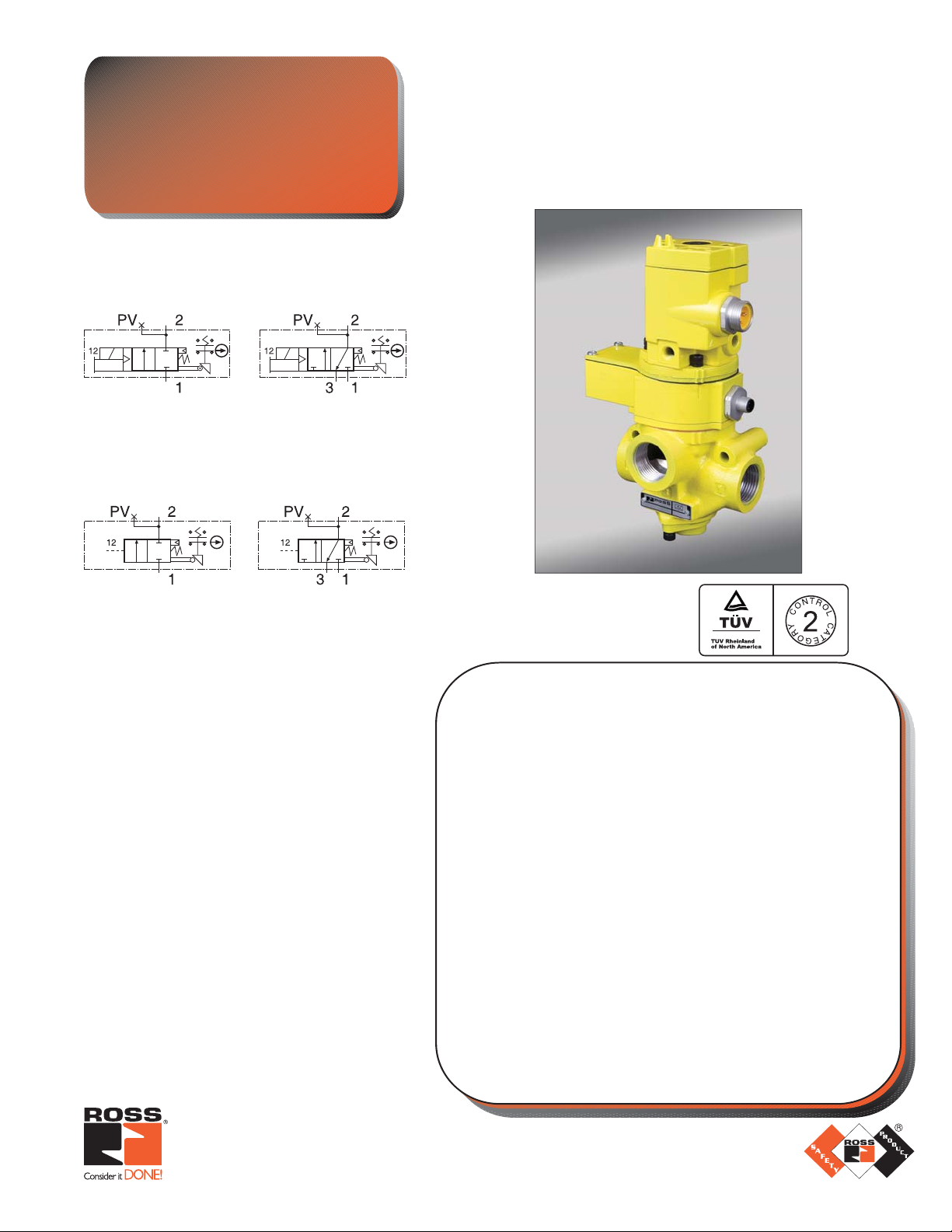
Series SV27 Sensing Valves
New Product
Information
Solenoid Pilot Controlled
2/2 3/2
Pressure Controlled
2/2 & 3/2 Normally Closed
with Position & State Sensing Feedback
for Category 2 Safety Applications
Air Dump/Release
3/2 Sensing Valve
(solenoid model shown)
2/2 3/2
Schematics shown for 3/4 and 1¼ bodies.*
STANDARD SPECIFICATIONS:
Pilot Solenoid: Rated for continuous duty.
Standard Voltages: 100–110 volts 50 Hz;
100–120 volts 60 Hz; 24, 110 volts DC.
Other voltages available.
Power Consumption: 87 VA inrush, 30 VA holding
on 50 or 60 Hz; 14 watts on DC.
Ambient Temperature: 40° to 120°F (4° to 50°C).
Media Temperature: 40° to 175°F (4° to 80°C).
Flow Media: Filtered air.
Inlet Pressure: 40 to 150 psig (2.8 to 10 bar).
Pilot Pressure: Equal to or greater than inlet
pressure.
Switch Current/Voltage Max.: 2.5 A/120 volts AC.
Switch Current/Voltage Min.: 50 mA/24 volts DC.
NOTE: Electrical life of switch varies with conditions
and voltage; rated in excess of 15 million cycles.
EN 954-1, ISO 13849-1,
& AS4024-1
(3/4 bodies only,
other sizes approval pending)
GENERAL:
ROSS’ new Series SV27 Sensing Valves, based upon the proven
Ser
ies 27 valve family, combine the tough, dirt tolerant characteristics
of poppet technology with sensing for actual internal position and state.
Electrical feedback is provided via a positively-driven, safety-rated
DPST (Double-Pole Single-Throw) switch with both normally open
(NO) and normally closed (NC) contacts. *For 3/4 and 1¼ bodies, the
DPST switch is actuated whenever the valve is not in the normal home
position. For size 2 body, the DPST switch is only actuated whenever
the valve IS in the normal home position.
An optional visual pressure indicator (988A30) or pressure switch
kit (608A86) can be installed into the 1/8 NPT pressure verifi cation
port (PV) for verifi cation of pressure release.
FEATURES:
• Solenoid pilot and pressure controlled versions
• Senses poppet position & state
• Electrical feedback via DPST switch (Double-Pole Single-Throw)
• Directly operated safety-rated force-guided status switch (DPST)
• Positive-break on 3/4 and 1¼ body valves
• Poppet construction for near zero leakage & high dirt tolerance
• Applications include Air Dump and Trapped-Pressure Release
www.rosscontrols.com
Page 2
Model Numbers* Valve Port Size C
SV27NC305407PSAA1A** 3/2 1/2 1 6.3 9.2 5.7 (145) 9.6 (244) 3.1 (77) 4.5 (2.0)
Function
Solenoid Pilot Controlled Models
v
Dimensions inches (mm)
1, 2 3 1 - 2 2 - 3 A B C lb (kg)
Weight
SV27NC305507PSAA1A** 3/2 3/4 1 7.7 11 5.7 (145) 9.6 (244) 3.1 (77) 4.5 (2.0)
SV27NC305607PSAA1A** 3/2 1 1 8.0 12 5.7 (145) 9.6 (244) 3.1 (77) 4.5 (2.0)
SV27NC105407PSAA1A** 2/2 1/2 – 7.7 N/A 5.7 (145) 9.3 (235) 3.1 (77) 4.6 (2.1)
SV27NC105507PSAA1A** 2/2 3/4 – 9.0 N/A 5.7 (145) 9.3 (235) 3.1 (77) 4.6 (2.1)
SV27NC105607PSAA1A** 2/2 1 – 9.0 N/A 5.7 (145) 9.3 (235) 3.1 (77) 4.6 (2.1)
SV27NC307607PSAA1A** 3/2 1 1½ 23 34 6.8 (173) 12.0 (303) 4.9 (123) 7.8 (3.5)
SV27NC307707PSAA1A** 3/2 1¼ 1½ 30 32 6.8 (173) 12.0 (303) 4.9 (123) 7.8 (3.5)
SV27NC307807PSAA1A** 3/2 1½ 1½ 30 31 6.8 (173) 12.0 (303) 4.9 (123) 7.8 (3.5)
SV27NC107607PSAA1A** 2/2 1 – 24 N/A 6.8 (173) 12.0 (303) 4.9 (123) 8.1 (3.7)
SV27NC107707PSAA1A** 2/2 1¼ – 29 N/A 6.8 (173) 12.0 (303) 4.9 (123) 8.1 (3.7)
SV27NC107807PSAA1A** 2/2 1½ – 29 N/A 6.8 (173) 12.0 (303) 4.9 (123) 8.1 (3.7)
Pressure Controlled Models
SV27NC305405ASAA 3/2 1/2 1 6.3 9.2 5.7 (145) 6.4 (163) 3.6 (91) 3.3 (1.5)
SV27NC305505ASAA 3/2 3/4 1 7.7 11 5.7 (145) 6.4 (163) 3.6 (91) 3.3 (1.5)
SV27NC305605ASAA 3/2 1 1 8.0 12 5.7 (145) 6.4 (163) 3.6 (91) 3.3 (1.5)
SV27NC105405ASAA 2/2 1/2 – 7.7 N/A 5.7 (145) 6.1 (155) 3.1 (79) 3.4 (1.6)
SV27NC105505ASAA 2/2 3/4 – 9.0 N/A 5.7 (145) 6.1 (155) 3.1 (79) 3.4 (1.6)
SV27NC105605ASAA 2/2 1 – 9.0 N/A 5.7 (145) 6.1 (155) 3.1 (79) 3.4 (1.6)
SV27NC307605ASAA 3/2 1 1½ 23 34 6.8 (173) 8.8 (222) 4.9 (123) 6.4 (2.9)
SV27NC307705ASAA 3/2 1¼ 1½ 30 32 6.8 (173) 8.8 (222) 4.9 (123) 6.4 (2.9)
SV27NC307805ASAA 3/2 1½ 1½ 30 31 6.8 (173) 8.8 (222) 4.9 (123) 6.4 (2.9)
SV27NC107605ASAA 2/2 1 – 24 N/A 6.8 (173) 8.7 (220) 4.1 (105) 6.7 (3.0)
SV27NC107705ASAA 2/2 1¼ – 29 N/A 6.8 (173) 8.7 (220) 4.1 (105) 6.7 (3.0)
SV27NC107805ASAA 2/2 1½ – 29 N/A 6.8 (173) 8.7 (220) 4.1 (105) 6.7 (3.0)
*NPT port threads. For BSPP threads, replace “N” in the model number with a “D”.
** “1A”=120 volts 60 Hz, solenoids. For 240 volts 60 Hz, change “1A” to “2A”; for 24 volts 60 Hz, change to “3A” ; for 24 volts DC, change to “1D”.
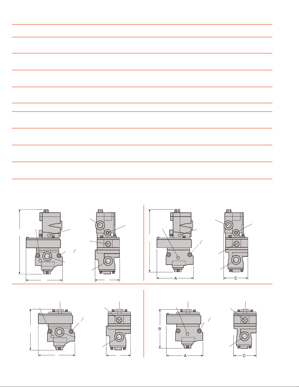
Port PV
(pressure
verification)
B
Port PV
(pressure
verification)
B
3/2 Solenoid Pilot Controlled Model
3-pin Mini
connector
Por t Y-3
(pilot exhaust)
5-pin M12
connector
2X O 0.34 (8.0)
Port 3 (exhaust)
Port 1(inlet)
[Port 2 (outlet
A
on opposite site]
C
3/2 Pressure Controlled Model
1/4 Signal Port
5-pin M12
connector
2X O 0.34 (8.0)
Port 3 (exhaust)
1/4 Signal Port
Port X-1
(1/8 external
pilot supply)
Port PV
(pressure
verification)
B
Port PV
(pressure
verification)
2/2 Solenoid Pilot Controlled Model
3-pin Mini
connector
Por t Y-3
(pilot exhaust)
2X O 0.34 (8.0)
5-pin M12
connector
Port 1(inlet)
[Port 2 (outlet
on opposite site]
2/2 Pressure Controlled Models
1/4 Signal Port
5-pin M12
connector
2X O 0.34 (8.0)
1/4 Signal Port
Port X-1
(1/8 external
pilot supply)
Port 1(inlet)
[Port 2 (outlet
A
on opposite site]
C
2 ROSS CONTROLS
Port 1(inlet)
[Port 2 (outlet
on opposite site]
®
Page 3

Model Numbers* Valve Port Size C
Function
Solenoid Pilot Controlled Models
v
Dimensions inches (mm)
1, 2 3 1 - 2 2 - 3 A B C lb (kg)
Weight
SV27NC309807PSAA1A** 3/2 1½ 2½ 68 70 8.7 (219) 11.8 (300) 6.4 (161) 18.1 (8.2)
SV27NC309907PSAA1A** 3/2 2 2½ 70 70 8.7 (219) 11.8 (300) 6.4 (161) 18.1 (8.2)
SV27NC309957PSAA1A** 3/2 2½ 2½ 70 71 8.7 (219) 11.8 (300) 6.4 (161) 18.1 (8.2)
Pressure Controlled Models
SV27NC309805ASAA 3/2 1½ 2½ 68 70 8.7 (219) 11.8 (300) 6.4 (161) 17.2 (7.8)
SV27NC309905ASAA 3/2 2 2½ 70 70 8.7 (219) 11.8 (300) 6.4 (161) 17.2 (7.8)
SV27NC309955ASAA 3/2 2½ 2½ 70 71 8.7 (219) 11.8 (300) 6.4 (161) 17.2 (7.8)
*NPT port threads. For BSPP threads, replace “N” in the model number with a “D”.
** “1A”=120 volts 60Hz, solenoids. For 240 volts 60 Hz, change “1A” to “2A”; for 24 volts 60 Hz, change to “3A”; for 24 volts DC, change to “1D”.
3/2 Solenoid Pilot Controlled Models
PV
12
Por t 3
(exhaust)
Port 1(inlet)
[Port 2 (outlet
on opposite site]
Port X-1
(1/8 external
pilot supply)
5-pin M12
connector
2X O 0.53 (13.5)
B
3-pin Mini
connector
Port PV
(pressure
A
verification)
C
3/2 Pressure Controlled Models
1/8” Signal Port
Por t 3
(exhaust)
2
Port 1(inlet)
[Port 2 (outlet
on opposite site]
2X O 0.53 (13.5)
5-pin M12
connector
B
13
Port PV
(pressure
A
verification)
C
Wiring Kits
These kits are available in lengths of 4 or 10 meters, with
a cord grip on each cable. The kits for SV27 solenoid
pilot controlled models come with 2 cables; one with
a 3-pin MINI connector for the solenoid and one with
a 5-pin M12 (Micro) connector for the sensing switch.
The kits for the pressure controlled models include only
one cable with a 5-pin M12 connector for the sensing
switch. (Note: Each cable has one connector.)
Solenoid Cable with
3-pin MINI Connector
BRN
PIN 3
BRN
BLUE
GRN/YEL
BLUE
PIN 2
GRN/YEL
(GROUND)
PIN 1
Sensing Switch Cable
with 5-pin M12 Connector
for 3/4 and 1¼ bodies.
WHT
PIN 2
BLK
WHT
GRAY
BRN
PIN 1
BLK
PIN 4
BLUE
PIN 3
BLUE
BRN
Current/Voltage Max. 2.5 A /120 VAC
Sensing Switch Cable
with 5-pin M12
Connector for 2 inch body.
BLUE
PIN 3
BLK
PIN 4
GRY
PIN 5
Current/Voltage Max. 2.5 A /120 VAC
Kit Number Valve Type Length (meters) No. of Cables
2239H77 Solenoid Pilot 4 2
2240H77 Solenoid Pilot 10 2
2241H77 Air Pilot 4 1
2242H77 Air Pilot 10 1
*For 3/4 and 1¼ inch bodies, the DPST switch is actuated
whenever the valve is not in the normal home position. For 2
inch bodies, the DPST switch is only actuated whenever the
valve is in the normal home position.
www.rosscontrols.com 3
WHT
PIN 2
BRN
PIN 1
GRY
PIN 5
Page 4

DISCLAIMER
These circuits are illustrative only and not intended to be used literally for your application. Each machine
is unique and has individual characteristics that must be considered when designing a safety circuit. In
addition, the referenced standards are not an exhaustive list. There may be many additional local, state,
national, and international standards as well as machine function specifi c standards pertinent to your
machine. This document is not a substitute for a complete risk assessment of a machine’s hazards,
professional circuit design or acquiring an in depth understanding of standards/regulations relevant to
an application or machine.
Optional Pressure Switch Kit (608A86)
Schematic
Note: Pressure switch closes on falling pressure of 5 psig.
Integrated Double-Pole Single-Throw Switch (DPST)
Switch States
for 3/4 and
1¼ bodies
General Illustration Safety-Related Applications
ROSS Controls is the leader in safety-related pneumatic products.
Shown here are a few examples of the variety of ROSS’ safetyrelated products and their applications. Please contact us if you
are interested in or confused about safety for your pneumatically
operated equipment.
3
1
®
L-O-X
Cat 4 Alternative Method LOTO
Switch States
for 2 inch body
ROSS Safety-Related Applications
* Cylinder hazard in 2 directions
* Pinch points
* Tooling or product damage
* Single point Lockout
* Press clutch/brake
3-Way
Control Reliable
Double Valve
2
* Counterbalance
* Monitored power systems
* Partial de-energization
* Vertical loads
* Cylinder hazard
Referenced Standards:
All standards are subject to revision. Parties are
encouraged to investigate and apply the most recent
editions of the standards indicated below.
OSHA 29 CFR 1910.147
CSA Z142-02
CSA Z460-05
ISO 13849-1
ISO 14118:2000
EN 1037
ANSI/ASSE Z244.1- 2003
ANSI/PMMI B155.1- 2006
ROSS CONTROLS
Customer Svs. 1-800-GET-ROSS
Technical Svs. 1-888-TEK-ROSS
www.rosscontrols.com
ROSS EUROPA GmbH
Germany
Fax: 49-6103-74694
info@rosseuropa.com
ROSS ASIA
Japan
Fax: 81-427-78-7256
custsvc@rossasia.co.jp
U.S.A.
®
K.K.
®
ROSS UK Ltd.
United Kingdom
Fax: 44-121-559-5309
sales@rossuk.co.uk
DISCLAIMER
These circuits are illustrative only and not intended to be used literally for your application. Each machine
is unique and has individual characteristics that must be considered when designing a safety circuit. In
addition, the referenced standards are not an exhaustive list. There may be many additional local, state,
national, and international standards as well as machine function specifi c standards pertinent to your
machine. This document is not a substitute for a complete risk assessment of a machine’s hazards,
professional circuit design or acquiring an in depth understanding of standards/regulations relevant to
an application or machine.
Standard ROSS warranty and cautions apply, available upon request or at www.rosscontrols.com
Cat 2 Alternative Method LOTO
3
1
2
3-Way SV27
Sensing Valve
®
ROSS CONTROLS
Fax: 91-44-2625-8730
rossindia@airtelbroadband.in
INDIA Pvt. Ltd.
India
WARRANTY and CAUTIONS
ROSS SOUTH AMERICA Ltda.
Brazil
Fax: 55-11-4335-3888
vendas@ross-sulamerica.com.br
Redundant PO Check
®
EEZ-ON
DIMAFLUID s.a.s.
France
Fax: 33-01-4945-6530
dimafluid@dimafluid.com
PO Check
ROSS CONTROLS
Fax: 86-21-6915-7960
alvinzhurong@vip.163.com
(CHINA) Ltd.
China
Printed in the U.S.A. – Rev. 3/09 © 2009 ROSS CONTROLS®. All Rights Reserved. Form NPS279
 Loading...