

Page 1
Series LT Leak Test Valves & Manifolds
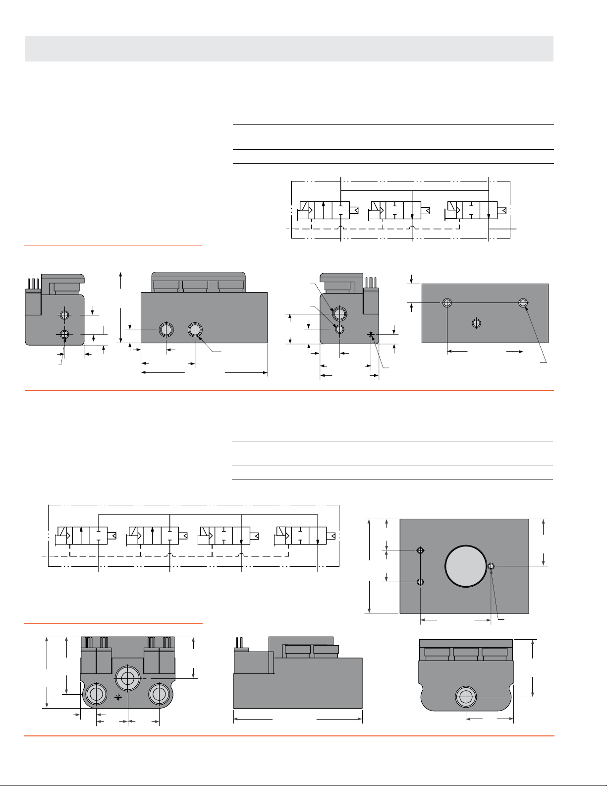
3/4 Manifolds
Manifold valve 3-port 4-position, normally closed.
Operator: External pilot, multi solenoid
actuated.
Applications: Single inlet for Decay, Flow, and
Differential tests.
Dimensions – inches (mm)
2.80
(71.1)
1/8-27 NPT
(2 Places)
P2
P3
0.77
(19.7)
0.77
(19.5)
(10.7)
0.42
0.52
(13.2)
TEST
1.00
(25.4)
2.14 (54.4)
INLET
5.00 (127.0)
The LT 3/4 manifold has excellent flow, is compact and adaptable. This product
can be field configured for flow, pressure decay, or differential pressure testing
by selecting different combinations of the three sensor ports.
Port Size Model Number Avg.
1 2 NC C
V
Dimensions inches (mm) Weight
Length Width Height lb (kg)
1/4 1/4 LT32NA27500W 2.2 5.00 (127.0) 2.33 (59.2) 2.80 (71.1) 2.9 (1.3)
1/4-18 NPT
(2 Places)
PILOT
1/4-18 NPT
1/8-27 NPT
1.19
(30.2)
0.59
(14.9)
INLET
EXHAUST
P1
0.78
(19.7)
2.01 (51.1)
2.33 (59.2)
P1
EXHAUST
BOTTOM VIEW
0.75
(19.1)
PILOT
0.38 (9.58)
10-32
P2
TEST
3.00 (76.2)
P3
1/4-20
Mounting Holes
4/4 Manifolds
Manifold valve 4-port 4-position, normally closed.
Operator: External pilot, multi-solenoid
actuated.
Applications: Flow and Pressure Decay.
PILOT
INLET 1
Dimensions – inches (mm)
2.84
(72.1)
2.28
(57.9)
0.63
(16.0)
INLET 1
PILOT
1.25
(31.8)
EXH
1.25
(31.8)
INLET 2
1.66
(42.2)
INLET 2
Port Size Model Number Avg.
1 2 NC C
V
Dimensions inches (mm) Weight
Length Width Height lb (kg)
1/2 1/2 LT44NA47500W 5.0 5.13 (130.3) 3.75 (95.3) 2.84 (72.1) 3.2 (1.5)
BOTTOM VIEW
1.25
EXHAUST
5.13 (130.3)
TEST
3.75
(95.3)
(31.8)
1.25
(31.8)
2.81 (71.4)
TEST PORT
Mounting Holes
1.88
(47.8)
1.88
(47.8)
1/4-20 UNC
2.28
(57.9)
24 © 2010, ROSS CONTROLS®.
All Rights Reserved.
Page 2
Series LT Leak Test Valves & Manifolds
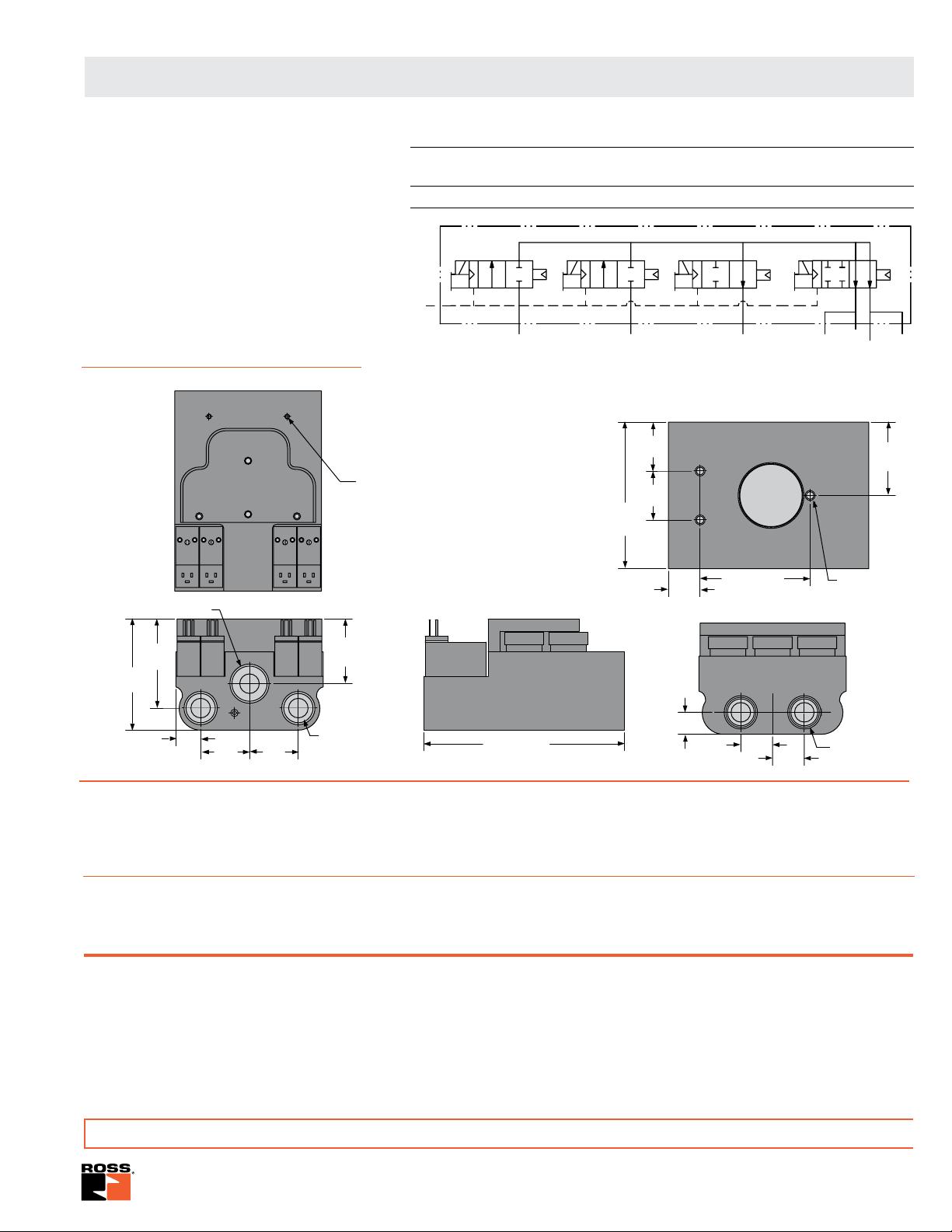
5/4 Manifolds
Manifold valve 5-port 4-position, normally closed.
Operator: External piloted, multi-solenoid
actuated.
Applications: Two channel Pressure Decay,
Differential Pressure.
Dimensions – inches (mm)
P1
3/4-14 NPT
P2
1/8-27 NPT
(2 Places)
Port Size Model Number Avg.
1 2 NC C
V
Dimensions inches (mm) Weight
Length Width Height lb (kg)
1/2 1/2 LT54NA47500W 5.0 5.13 (130.3) 3.75 (95.3) 2.84 (72.1) 3.2 (1.5)
PILOT
INLET 1
INLET 2
3.75
(95.3)
1.25
(31.8)
1.25
(31.8)
0.812
(20.6)
EXHAUST
BOTTOM VIEW
2.81 (71.4)
TEST 1
P1
TEST 2
1/4-20 UNC
Mounting Holes
1.88
(47.8)
P2
1.66
(42.2)
1/2-14 NPT
(2 Places)
5.13 (130.3)
0.56 (14.3)
TEST PORT
2
0.81
(20.6)
TEST PORT
1
0.81
(20.6)
1/2-14 NPT
(2 Places)
2.84
(72.1)
2.28
(57.9)
INLET 1
0.63
(16.0)
PILOT
1.25
(31.8)
EXH
INLET 2
1.25
(31.8)
The LT 4/4 and 5/4 manifolds are “all in one” directional control valves designed to fill, isolate, and test pressure containing vessels.
All manifolds contain integrated sensor ports for flow, pressure decay or differential pressure testing. With dual inlet ports, and
independent actuation of four internal poppets these manifolds also provide a flexible, high flow, compact air distribution solution
for many other applications.
* For 120 volts AC, 50/60 Hz, replace suffix “W” with “Z”, e.g., LT32NA27500Z.
Electrical connectors not included, see page 26 for ordering information.
STANDARD SPECIFICATIONS:
For Series LT 3/4, 4/4, 5/4 Manifolds.
Pilot Solenoid: DC power. Rated for continuous duty.
Standard Voltages: 24 volts DC; 120 volts AC, 50/60 Hz.
Power Consumption:
Per Solenoid: 3 VA on AC; 2.5 watts on DC.
Ambient/Media Temperature: 40° to 120°F (4° to 50°C).
Flow Media: Filtered air; 5 micron recommended.
Sensor Port: 1/8 NPT sensor ports.
Pilot Pressure: 50 to 145 psi (3.4 to 10 bar). Must be equal to
or greater than inlet pressure.
Inlet Pressure: 2 to 145 psi (0.13 to 10 bar).
Port Threads: NPT.
IMPORTANT NOTE: Please read carefully and thoroughly all of the CAUTIONS on the inside back cover.
www.rosscontrols.com 25
Page 3

Series LT Leak Test Valves & Manifolds
ELECTRICAL CONNECTORS: For Series LT Valves.
Part Numbers of Electrical Connectors
Valve Port Lighted Connector Only Lighted Connector Pre-wired*
Size
1/4, 1/2 2306K77W 2306K77Z 2307K77W 2307K77Z
*Pre-wired connectors are lighted and include a 2 meter (6½ ft.) cord.
The Dale series CX and LT can be combined to simplify the most complex test circuits. The LT manifold with integrated sensor
ports is the primary valve used for the fill, isolate and test functions. In this example the test port of the LT is connected to the
CX manifold allowing four chambers to be tested one at a time. The flexibility of combining the LT and CX manifolds creates a
compact package, reduces leak paths, and provides an all in one test solution.
24 volts DC 110 Volts AC 24 volts DC 110 Volts AC
Applications Examples
Manifold Shown below:
2/2 Valve, 4-Station, Normally Closed
Port 1/2”, 24 Volts DC
Manifold Shown below:
3/4, Leak Test Manifold, 24 Volts DC
LT32NA27500W
CX14NA47514W
2 2 2 2
To Chambers Being Tested
TEST
INLET
Supply
The CX series manifold port pressure independence and bidirectional flow capabilities allows the user to create a simple manifold
solution for the most complex test circuits. The following example shows a test performing a vacuum test, followed by a low
pressure test, and finishing with a high pressure test using a single CX manifold. The vacuum, low pressure and high pressure
valves are NC (normally closed). The isolation and exhaust valves are NO (normally open), allowing the valve to go to a safe
mode if power is cut.
Note: Once the unit under test is filled and the
isolation poppet is closed the pressure or vacuum
in the common valve chamber can be exhausted.
2 2 2 2
This prevents the possibility of leak up that could
cause the unit under test to pass a test it should
have failed.
Vacuum
Inlet
26 © 2010, ROSS CONTROLS®.
High
Pressure
Low
Pressure
Inlet
All Rights Reserved.
Inlet
2
Unit Under
Test
Common
Inlet
Port Blocked
Exhaust
 Loading...