

Page 1
1
35
24
14
Series W74 Poppet Valves for ANSI Bases
A
B
C
A
B
C
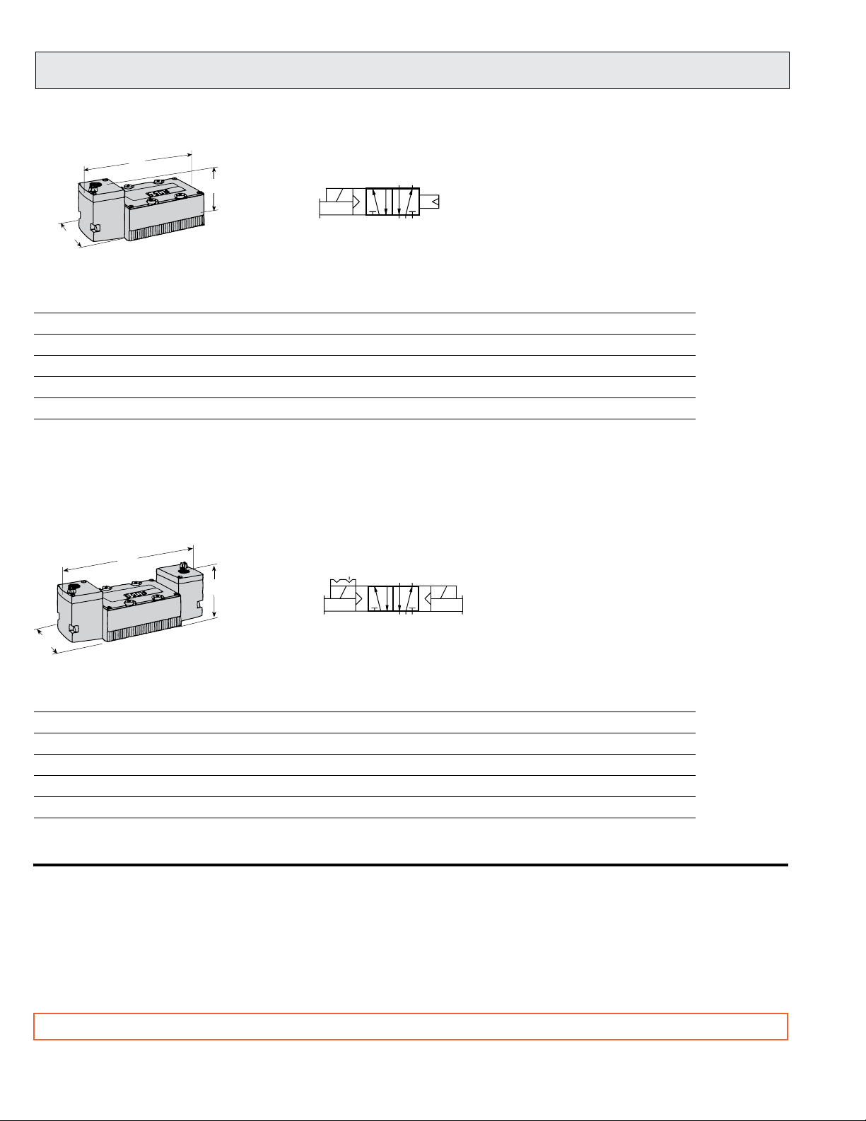
5/2 Valves – Single Solenoid Pilot Controlled, Air Return
ANSI Range of Valve Model Number* Avg. Dimensions inches (mm) Weight
Size Port Sizes Std. Temp. High Temp. C
1 1/4 - 3/8 W7476A2331 W7476A2336 0.9 6.5 (164) 2.0 (50) 2.4 (59) 3.0 (1.4)
2.5 3/8 - 1/2 W7476A3331 W7476A3336 2.0 7.3 (185) 2.7 (67) 3.6 (91) 3.0 (1.4)
4 3/8 - 3/4 W7476C4331 W7476B4336 4.2 8.4 (212) 3.5 (88) 4.0 (101) 5.0 (2.3)
10 3/4 - 1¼ W7476A6331 W7476A6336 11 9.8 (249) 3.9 (99) 4.0 (101) 6.1 (2.8)
20 1¼ - 1½ W7476A8331 W7476A8336 22 15.0 (381) 5.6 (142) 4.1 (104) 18.5 (8.3)
* Base not included. See pages 8-10 for accessories.
A B C lb (kg)
V
5/2 Valves – Double Solenoid Pilot Controlled, Detented
ANSI Range of Valve Model Number* Avg. Dimensions inches (mm) Weight
Size Port Sizes Std. Temp. High Temp. C
1 1/4 - 3/8 W7476A2332 W7476A2337 0.9 7.7 (194) 2.0 (50) 2.4 (59) 3.5 (1.6)
2.5 3/8 - 1/2 W7476A3332 W7476A3337 2.0 8.8 (224) 2.7 (67) 3.6 (91) 4.0 (1.8)
4 3/8 - 3/4 W7476C4332 W7476C4337 4.2 9.8 (249) 3.5 (88) 4.0 (101) 5.5 (2.5)
10 3/4 - 1¼ W7476A6332 W7476A6337 11 11.3 (286) 3.9 (99) 4.0 (101) 10.8 (4.9)
20 1¼ - 1½ W7476A8332 W7476A8337 22 16.5 (417) 5.6 (142) 4.1 (104) 19.8 (8.9)
* Base not included. See pages 8-10 for accessories.
STANDARD SPECIFICATIONS: For valves on this page.
Solenoids: AC or DC power.
Standard Voltages: See page 110; consult ROSS.
Power Consumption: Each solenoid.
Size 1 models: 10 VA inrush, 9 VA holding on 50 or 60 Hz;
5 watts on DC.
All other sizes: 87 VA inrush, 30 VA holding on 50 or 60 Hz;
14 watts on DC.
A B C lb (kg)
V
Indicator Light: Size 4, 10 & 20 models only.
Ambient Temperature: 40° to 120°F (4° to 50°C); extended to
175°F (80°C) for High Temperature models.
Media Temperature: 40° to 175°F (4° to 80°C); extended to 220°F
(105°C) for High Temperature models.
Flow Media: Filtered air; 5 micron recommended.
Inlet Pressure: 30 to 150 psig (2 to 10 bar).
Pilot Pressure: Must be equal to or greater than inlet pressure.
IMPORTANT NOTE: Please read carefully and thoroughly all of the CAUTIONS on the inside back cover.
6
© 2009, ROSS CONTROLS®. All Rights Reserved.
Page 2
1
35
24
14
A
B
C
A
B
C
Series W74 Poppet Valves for ANSI Bases
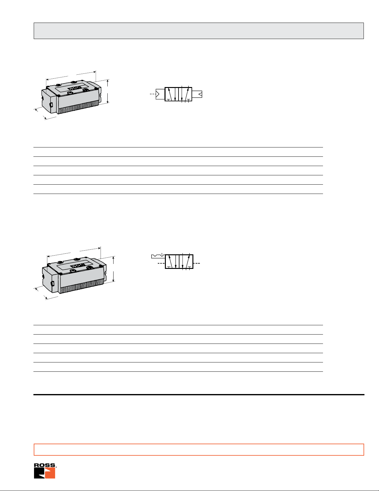
5/2 Valves – Single Pressure Controlled, Air Return
ANSI Range of Valve Model Number* Avg. Dimensions inches (mm) Weight
Size Port Sizes Std. Temp. High Temp. C
1 1/4 - 3/8 W7456A2331 W7456A2336 0.9 5.1 (128) 2.0 (50) 2.3 (58) 2.5 (1.1)
2.5 3/8 - 1/2 W7456A3331 W7456A3336 2.0 5.7 (145) 2.6 (66) 2.6 (66) 2.0 (0.9)
4 3/8 - 3/4 W7456C4331 W7456C4336 4.2 6.9 (174) 3.5 (88) 2.8 (70) 3.3 (1.5)
10 3/4 - 1¼ W7456A6331 W7456A6336 11 8.3 (211) 3.9 (99) 2.7 (68) 7.3 (3.3)
20 1¼ - 1½ W7456A8331 W7456A8336 22 13.5 (342) 5.6 (142) 3.0 (76) 17.5 (7.9)
* Base not included. See pages 8-10 for accessories.
A B C lb (kg)
V
5/2 Valves – Double Pressure Controlled, Detented
ANSI Range of Valve Model Number* Avg. Dimensions inches (mm) Weight
Size Port Sizes Std. Temp. High Temp. C
1 1/4 - 3/8 W7456A2332 W7456A2337 0.9 5.1 (128) 2.0 (50) 2.3 (58) 2.5 (1.1)
2.5 3/8 - 1/2 W7456A3332 W7456A3337 2.0 5.7 (145 2.6 (66) 2.6 (66) 2.0 (0.9)
4 3/8 - 3/4 W7456C4332 W7456C4337 4.2 6.9 (174) 3.5 (88) 2.8 (70) 3.3 (1.5)
10 3/4 - 1¼ W7456A6332 W7456A6337 11 8.3 (211) 3.9 (99) 2.7 (68) 7.3 (3.3)
20 1¼ - 1½ W7456A8332 W7456A8337 22 13.5 (342) 5.6 (142) 3.0 (76) 17.5 (7.9)
* Base not included. See pages 8-10 for accessories.
STANDARD SPECIFICATIONS: For valves on this page.
Ambient/Media Temperature: 40° to 175°F (4° to 80°C); media
temperature extended to 220°F (105°C) for High Temperature
models.
A B C lb (kg)
V
Flow Media: Filtered air; 5 micron recommended.
Inlet Pressure: 30 to 150 psig (2 to 10 bar).
Pilot Pressure: Must be equal to or greater than inlet pressure.
IMPORTANT NOTE: Please read carefully and thoroughly all of the CAUTIONS on the inside back cover.
www.rosscontrols.com
7
Page 3

4
2
Y2
12
A
B
C
Sub-Bases for Series W70 & W74 ANSI Valves
The sub-base numbers shown in the chart below
specify pressure ports with NPT threads, and
electrical openings with 1/2 NPT threads.
Sub-base for
C
= 4.2 valves illustrated.
V
ANSI SUB-BASES
Type of Sub-Base
Port None One Two C
1/4 500B91 525K91 526K91 0.9 to 1.0 2.8 (72) 1.6 (41) 6.2 (157)
3/8 501B91 527K91 528K91 0.9 to 1.0 2.8 (72) 1.6 (41) 6.2 (157
3/8 474K91 482K91 484K91 2.0 to 2.5 3.6 (91) 1.5 (37) 7.1 (180)
1/2 475K91 483K91 485K91 2.0 to 2.5 3.6 (91) 1.5 (37) 7.1 (180)
3/8 361B91 — — 4.2 3.3 (84) 2.7 (67) 7.2 (183)
Side-Ported
3/4 363B91 — — 4.2 3.3 (84) 2.7 (67) 7.2 (183)
3/4 364B91 — — 10 to 11 5.1 (130) 3.8 (96) 10.5 (266)
1 365B91 — — 10 to 11 5.1 (130) 3.8 (96) 10.5 (266)
1¼ 366B91 — — 10 to 11 5.1 (130) 3.8 (96) 10.5 (266)
1¼ 367B91 — — 22 6.4 (163) 3.7 (94) 12.4 (314)
1½ 368B91 — — 22 6.4 (163) 3.7 (94) 12.4 (314)
1/4 499B91 529K91 530K91 0.9 to 1.0 2.8 (72) 1.5 (37) 6.2 (157)
Side and
Bottom-Ported
1/2 370B91 — — 4.2 3.4 (86) 2.7 (67) 7.2 (183)
3/4 371B91 — — 4.2 3.4 (86) 2.7 (67) 7.2 (183)
3/4 372B91 — — 10 to 11 5.1 (130) 3.9 (99) 10.5 (266)
1 373B91 — — 10 to 11 5.1 (130) 3.9 (99) 10.5 (266)
Bottom-Ported
1¼ 375B91 — — 22 6.4 (163) 3.8 (98) 12.4 (314)
1½ 376B91 — — 22 6.4 (163) 3.8 (98) 12.4 (314)
*NPT port threads. For BSPP threads, add a “D” prefix to the model number; for JIS threads, add a “J” prefix to the model number.
Outlet Indicator Lights in Base* Avg. Dimensions inches (mm)
A B C
V
1/2 362B91 — — 4.2 3.3 (84) 2.7 (67) 7.2 (183)
3/8 476K91 477K91 486K91 2.0 to 2.5 3.6 (91) 1.5 (37) 7.1 (180)
3/8 369B91 — — 4.2 3.4 (86) 2.7 (67) 7.2 (183)
1¼ 374B91 — — 10 to 11 5.1 (130) 3.9 (99) 10.5 (266)
Electrical connection conforming to ANSI standard B93.55M is available.
For more information, refer to ROSS Bulletin 379 (form number A10090).
IMPORTANT NOTE: Please read carefully and thoroughly all of the CAUTIONS on the inside back cover.
8
© 2009, ROSS CONTROLS®. All Rights Reserved.
Page 4

Manifolds for Series W70 & W74 ANSI Valves
A
B
C
The numbers of the manifold stations shown in the chart
below specify pressure ports with NPT threads and electrical
openings with 1¼ NPT threads.
All necessary hardware and seals for manifold assembly are
included with each manifold station.
Indicator Lights: As shown in the chart below, the smaller
sizes of manifolds are available with indicator lights. These
lights are located in the end plate covering the electrical
cavity.
Manifold Note: The port positions of the solenoid controlled
and the pressure controlled manifolds are not the same.
For this reason these stations cannot be mixed in the
same installation. If both types of valves must be used
in the same installation, use only manifold stations for
solenoid controlled valves.
ANSI MANIFOLDS
Type of Manifold
Port None One** Two** C
1/4 502B91 531K91 532K91 0.9 to 1.0 2.3 (57) 2.3 (58) 8.0 (205)
3/8 503B91 533K91 534K91 0.9 to 1.0 2.3 (57) 2.3 (58) 8.0 (205)
3/8 472K91 478K91 480K91 2.0 to 2.5 2.3 (57) 2.3 (57) 8.0 (205)
1/2 473K91 479K91 481K91 2.0 to 2.5 2.3 (57) 2.3 (57) 8.0 (205)
For Solenoid 3/8 377B91 — — 4.2 3.54 (90) 3.7 (94) 9.1 (232)
Controlled 1/2 378B91 — — 4.2 3.54 (90) 3.7 (94) 9.1 (232)
Valves 3/4 379B91 — — 4.2 3.54 (90) 3.7 (94) 9.1 (232)
3/4 380B91 — — 10 to 11 4.25 (108) 4.1 (104) 13.3 (338)
1 381B91 — — 10 to 11 4.25 (108) 4.1 (104) 13.3 (338)
1¼ 382B91 — — 10 to 11 4.25 (108) 4.1 (104) 13.3 (338)
1/4 359B91 — — 0.9 to 1.0 2.26 (57) 2.3 (58) 6.3 (160)
3/8 360K91 — — 0.9 to 1.0 2.26 (57) 2.3 (58) 6.3 (160)
3/8 468B91 — — 2.0 to 2.5 2.80 (71) 2.7 (69) 6.9 (174)
For Pressure 1/2 469B91 — — 2.0 to 2.5 2.80 (71) 2.7 (69) 6.9 (174)
Controlled 3/8 383B91 — — 4.2 3.54 (90) 3.7 (94) 9.2 (232)
Valves 1/2 384B91 — — 4.2 3.54 (90) 3.7 (94) 9.2 (232)
3/4 385B91 — — 4.2 3.54 (90) 3.7 (94) 9.2 (232)
3/4 386B91 — — 10 to 11 4.25 (108) 4.1 (104) 13.3 (338)
1 387B91 — — 10 to 11 4.25 (108) 4.1 (104) 13.3 (338)
1¼ 388B91 — — 10 to 11 4.25 (108) 4.1 (104) 13.3 (338)
*NPT port threads. For BSPP threads, add a “D” prefix to the model number; for JIS threads, add a “J” prefix to the model number.
** Specify voltage on manifold.
Standard Voltages: 24 volts DC; 110 volts AC, 50 Hz ; 120 volts AC, 60 Hz; 200 volts AC, 50 Hz; 240 volts AC, 60 Hz. For other voltages, consult ROSS.
Outlet Indicator Lights in Manifold* Avg. Dimensions inches (mm)
V
Typical Manifold Station
A B C
ASSEMBLED MANIFOLDS
Valves and manifold stations can be assembled by ROSS to precise specifications.
The assembly is then ready for integration into your system.
For detailed information about such assemblies, consult your ROSS Distributor or call ROSS
in the U.S.A. at 1-888-TEK-ROSS (835-7677) or 1-706-356-3708.
IMPORTANT NOTE: Please read carefully and thoroughly all of the CAUTIONS on the inside back cover.
www.rosscontrols.com
9
Page 5

Accessories
Interposed Pressure Regulators
Both single and double interposed regulators are available
for valves with CV ratings up to 4.2. A regulator is bolted to
the valve’s sub-base or manifold station, and the valve is
then bolted to the regulator. This mounting method allows
the valve to be removed and replaced without disturbing the
regulator.
Single pressure regulators provide the same regulated
pressure at both outlet ports. Double pressure regulators allow
the pressure at each outlet port to be set independently.
A locking type knob is used to set the regulated pressure at
any point in the range of:
5 to 100 psig (0.3 to 7 bar) for size 1 and 2 models;
5 to 125 psig (0.3 to 8.5 bar) for size = 4.2 models.
Maximum inlet pressure is 150 psig (10 bar).
Pressure gauge(s) included.
Order regulators by the part numbers shown at the right.
Single
Double * Remote
Single Solenoid Air
C
= 0.9, Size 1 Valves: 840C91 841C91 713C91
V
= 2.0, Size 2.5 Valves: 626C91 627C91 714C91
C
V
= 4.2, Size 4 Valves: 632C91 633C91 715C91
C
V
* Double regulator only for W70 spool valves.
Double interposed regulators will reverse output
ports - the 12 solenoid will pressurize the 4 port,
the 14 solenoid will pressurize the 2 port - which may
cause unexpected, potentially dangerous cylinder
WARNING
movement at valve pressurization.
Manual Override Kits for Solenoid Pilot Controlled Valves
FLUSH BUTTON
Locking type ............... Kit 792K87
Flush flexible manual overrides are standard on solenoid pilot
controlled valves with CV ratings of 2.0 or larger. Both locking
and non-locking metal override buttons are also available for
these models.
Each of the override buttons in the kits at the right is made
of metal and is spring-returned. The locking type button,
however, can be kept in the actuated position by turning the
slot in the top of the button with a screwdriver.
Order by the kit numbers shown at the right.
Non-locking type ......... Kit 790K87
EXTENDED BUTTON
Non-locking type...........Kit 791K87
EXTENDED BUTTON WITH PALM
ACTUATOR
Non-locking type..........Kit 984H87
10
© 2009, ROSS CONTROLS®. All Rights Reserved.
 Loading...