

Page 1
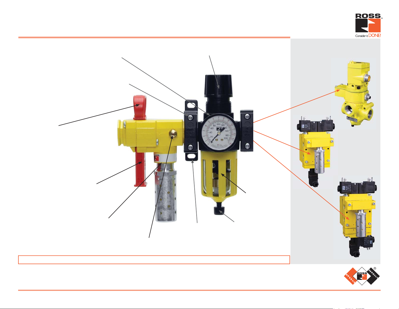
Modular L-O-X® Air Entry Combination
Lockout Valve with Integrated Filter/Regulator
Reverse fl ow self-relieving piston-type
for assured full fl ow exhaust.
Modular mounting for easy servicing.
Easy to operate
(positive push/pull operation-detented).
Only lockable in the off position.
Removable cap for tamper-resistant
pressure setting.
Combination Examples
Cat-2 Applications
SV Sensing Valve
Cat-3 Applications
DM1 Series E
Available in
polycarbonate or
metal bowl.
Has a full size exhaust port
(equal to or larger than supply).
Has a visible indicator of
Optional Mounting
Bracket
Manual or Auto Drain
(fl oat drain optional
with metal bowl).
Cat-4 Applications
DM2® Series E
pressure release (verifi cation port).
WARRANTY and CAUTIONS: Standard ROSS warranty and cautions apply, available upon request or at www.rosscontrols.com.
®
ROSS CONTROLS
U.S.A.
Customer Svs. 1-800-GET-ROSS
Technical Svs. 1-888-TEK-ROSS
www.rosscontrols.com
Printed in the U.S.A. – Rev. 05/09 © 2009, ROSS CONTROLS®. All Rights Reserved. Form PSI005
ROSS EUROPA GmbH
Germany
Fax: 49-6103-74694
info@rosseuropa.com
ROSS ASIA® K.K.
Japan
Fax: 81-427-78-7256
custsvc@rossasia.co.jp
ROSS UK Ltd.
United Kingdom
Fax: 44-121-559-5309
sales@rossuk.co.uk
ROSS CONTROLS® INDIA Pvt. Ltd.
India
Fax: 91-44-2625-8730
rossindia@airtelbroadband.in
ROSS SOUTH AMERICA Ltda.
Brazil
Fax: 55-11-4335-3888
vendas@ross-sulamerica.com.br
DIMAFLUID s.a.s.
France
Fax: 33-01-4945-6530
dimafluid@dimafluid.com
ROSS CONTROLS (CHINA) Ltd.
China
Fax: 86-21-6915-7960
alvinzhurong@vip.163.com
Page 2
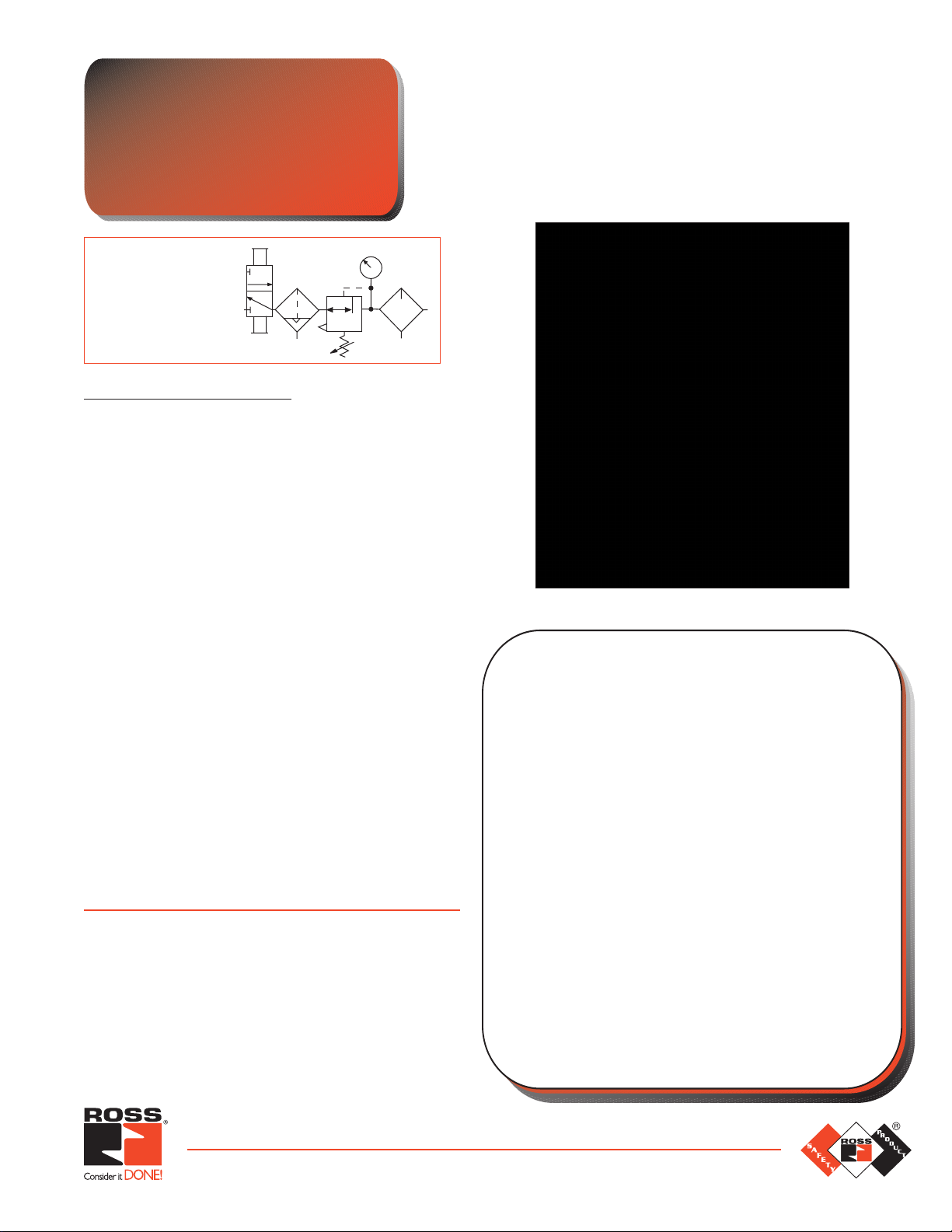
Modular L-O-X®
New Product
Introduction
Lockout/Filter/Regulator
ISO
Symbol
Lockout
Automatic Drain
Self-relieving
STANDARD SPECIFICATIONS
Ambient/Media Temperature:
Plastic or Metal bowl: 40° to 125°F (4° to 52°C).
Body: Zinc.
Bonnet: Acetal.
Bowl: 4-oz (120-ml) polycarbonate plastic with zinc
shatterguard; optional zinc bowl with clear nylon sight glass
6-oz (178-ml).
Bowl Drain: Internal automatic drain; optional manual dr ain
or float drain (metal bowl only).
Cap Color: Black.
Filter Element: 5-micron rated polyethylene filter element;
optional 40-micron element.
Fluid Media: Compressed air.
Inlet Pressure: 15 psig (1 bar) minimum with automatic drain.
Plastic bowl: 150 psig (10 bar).
Metal bowl: 200 psig (14 bar).
Outlet Pressure: Adjustab le up to 150 psig (10 bar); o ptional
adjusting springs.
Pressure Adjustment: Removable, knob.
Pressure Gauge: 0 to 200 psig (14 bar); 1/4 NPT gauge
ports front and rear; 0-60 psig (4 bar) optional.
Panel Mounting: 1.56 inch (37.1 mm) hole required.
Ports: Tapped inlet, outlet and exhaust ports.
Seals/Elastomers: Carboxylated Nitrile (XNBR).
Valve: Zinc.
Valve Color: Yellow body, red lockout slide.
Slide: Acetal.
Threads: NPT standard, BSPP.
Referenced Standards:
All standards are subject to revision. Parties are
encouraged to investigate and apply the most recent
editions of the standards indicated below.
1
OSHA 29 CFR 1910.147
CSA Z142-02
CSA Z460-05
ISO 13849-1
ISO 14118:2000
EN 1037
ANSI/ASSE Z244.1- 2003 (R2010)
ANSI/PMMI B155.1- 2010
2
Air Entry Combination
Lockout Valve with
Integrated Filter/Regulator
GENERAL:
The Modular L-O-X® Air Entry is a combination Lockout
Valve with Integrated Filter/Regulator in a high flow,
compact space saving design. Full flow exhaust meets
all the applicable standards.
FEATURES:
• Filter and regulator consolidated into a single space-saving
assembly
• Modular mounting for easy servicing
• Internal automatic drain; optional manual drain or float drain
(metal bowl only)
• Reverse flow, self-relieving piston-type regulator; nonrelieving optional
• Tamper-resistant pressure setting
• Has a visible indicator of pressure release (verification port)
• Only lockable in the off position
• Has a full size exhaust port (equal to or larger than supply)
• Easy to operate (positive push/pull operation-detented)
• Optional EEZ-ON
• Packaging
• Conveyor panels
®
operation availab le
APPLICATIONS:
• Material handling
• All Air Entry points
www.rosscontrols.com
Page 3

Modular L-O-X® Air Entry Combination
250
010
scfm
FLOW
l/s
0 5
20
psi
100
OUTLET PRESSURE
1.4
2.8
4.2
5.6
bar
7.0
INLET PRESSURE: 91 psig (6.3 bar)
0
scfm
FLOW
l/s
0
00
20 30 40 50 60 70 80 90 100 110
10 15 20 25 30 35 40 45 50
1/2 Ports
1/4 Ports
3/8 Ports
40
60
80
20
psi
100
OUTLET PRESSURE
1.4
2.8
4.2
5.6
bar
7.0
00
40
60
80
20
psi
100
OUTLET PRESSURE
1.4
2.8
4.2
5.6
bar
7.0
00
40
60
80
Ports: 1/4, 3/8, 1/2
Flow to 105 scfm
DIMENSIONS inches (mm)
Bowl A B * C ** Depth † lb (kg)
Polycarbonate 7.7 (195.6) 4.81 (122.2) 3.23 (82.0) 2.9 (73.7) 3.12 (1.4)
Metal 7.7 (195.6) 6.43 (163.4) 3.23 (82.0) 2.9 (73.7) 3.18 (1.4)
* Bowl removal clearance: add 3.1 (79).
** Dome removal clearance: add 0.63 (16).
† Less gauge.
Inlet pressure psig (bar)
0.34
0.31
0.28
0.24
0.21
0.17
0.14
0.10
0.06
0.03
5
4.5
4
3.5
3
2.5
2
1.5
1
0.5
0
0
psid
bar
scfm
36 (2.5) 92 (6.3) 145 (10.0)
DIFFERENTIAL PRESSURE
050 100 150 200 250
l/s
0 25 50 75 100
1/4 Ports
A
Weight †
LOCKOUT VALVE FLOW CHARACTERISTICS
Inlet pressure psig (bar)
0.34
0.31
0.28
0.24
0.21
0.17
0.14
0.10
0.06
0.03
5
4.5
4
3.5
3
2.5
2
1.5
1
0.5
0
0
psid
bar
scfm
36 (2.5) 92 (6.3) 145 (10.0)
DIFFERENTIAL PRESSURE
050 100 150 200 250
0 25 50 75 100
l/s
FILTER/REGULATOR FLOW CHARACTERISTICS
C
B
Inlet pressure psig (bar)
36 (2.5) 92 (6.3) 145 (10.0)
1/2 Ports
DIFFERENTIAL PRESSURE
050 100 150 200
0 25 50 75 100
3/8 Ports
0.34
0.31
0.28
0.24
0.21
0.17
0.14
0.10
0.06
0.03
5
4.5
4
3.5
3
2.5
2
1.5
1
0.5
0
0
psid
bar
scfm
l/s
MD3 53P B A B 5 B B –
BOWL SIZE
53P - Polycarbonate Bowl (4 oz)
53M - Metal Bowl with sight gauge (6 oz)
ELEMENT TYPE
A - 40 Micron
B - 5 Micron; standard
Element Rating Kit Number
5-µm (Std. element) ................................936K77
40-µm ..........................................938K77
Accessories not included with the product, see page 4
for ordering information.
2 © 2012, ROSS CONTROLS
BOWL DRAIN
A - Auto Drain/Differential Pressure
M - Manual Drain
F - Float Drain (metal bowl only)
REPLACEMENT FILTER ELEMENT KITS
HOW TO ORDER
PIPE SIZE
2 - 1/4 NPTF
3 - 3/8 NPTF
4 - 1/2 NPTF
C - 1/4 BSPP
D - 3/8 BSPP
E - 1/2 BSPP
®
. All Rights Reserved.
GAUGE
A - No Gauge
B - (0-200 psig)
C - (0-60 psig)
D - No Gauge with Panel Mount Nut
E - (0-200 psig) Gauge with Panel Mount Nut
F - (0-60 psig) Gauge with Panel Mount Nut
ADJUSTMENT RANGE
A - 0-150 psig (0-10 bar); reverse flow
B - 0-100 psig (0-6.8 bar); standard, reverse flow
C - 0-50 psig (0-3.4 bar); reverse flow
ADD ON L-O-X
®
1 - Outlet Side
2 - Inlet Side
3 - L-O-X® with EEZ-ON
on Outlet Side
4 - L-O-X
on Inlet Side
X - no L-O-X
®
with EEZ-ON®
®
®
Page 4

Modular L-O-X® Air Entry Packages
Model Air Entry Port Size C
Number Type In-Out Exh. 1 to 2 2 to 3 Length Width Depth
Cat-2 with SV27 RC208-09 FR 1/2 1 6.3 9.2 14.80 (374.9) 11.00 (279.0) 6.60 (167.7)
Cat-2 with SV27 RC208L-09 FRL 1/2 1 6.3 9.2 14.80 (374.9) 11.00 (279.0) 6.60 (167.7)
Cat-3 with DM1 Series E RC304-09 FR 1/4 1/2 1.3 2.4 13.00 (330.0) 11.00 (279.0) 5.40 (134.7)
Cat-3 with DM1 Series E RC306-09 FR 3/8 1/2 1.9 2.4 13.00 (330.0) 11.00 (279.0) 5.40 (134.7)
Cat-3 with DM1 Series E RC304L-09 FRL 1/4 1/2 1.3 2.4 13.00 (330.0) 11.00 (279.0) 5.40 (134.7)
Cat-3 with DM1 Series E RC306L-09 FRL 3/8 1/2 1.9 2.4 13.00 (330.0) 11.00 (279.0) 5.40 (134.7)
Cat-4 with DM
Cat-4 with DM
Cat-4 with DM
Cat-4 with DM
* NPT port threads. Specify voltage and hertz when ordering.
2®
Series E RC404-09 FR 1/4 1/2 1.3 2.4 13.00 (330.0) 11.00 (279.0) 5.40 (134.7)
2®
Series E RC406-09 FR 3/8 1/2 1.9 2.4 13.00 (330.0) 11.00 (279.0) 5.40 (134.7)
2®
Series E RC404L-09 FRL 1/4 1/2 1.3 2.4 13.00 (330.0) 11.00 (279.0) 5.40 (134.7)
2®
Series E RC406L-09 FRL 3/8 1/2 1.9 2.4 13.00 (330.0) 11.00 (279.0) 5.40 (134.7)
V
Air Entry Package with 3/2 Normally Closed
Sensing V alve
• Pre-engineered panel-mounted design with air entry via filter and
regulator “FR”, or filter, regulator, and lubricator “FRL”.
• Includes 3/2 Normally Closed Sensing Valve which senses poppet position
and state. Electrical feedback via DPST switch (double-pole, single-throw).
• Applications include Air Dump and Trapped-Pressure Release.
Dimensions (inches/mm)
Air Entry Packages with Control Reliable
Energy Isolation
• Pre-engineered panel-mounted design with air entry
via a filter and regulator “FR”, or filter, regulator and
lubricator “FRL”.
• Includes DM
a) Self-contained dynamic monitoring system requires no further valve
monitoring controls.
b) Ready-to-run: If an abnormality clears itself upon the remo val of electricity to both
solenoids, it will be ready-to-run again. It does not remember the abnormality & stay
in a locked-out state until intentionally reset. Therefore, cumulative abnormalities
may go undetected.
c) Status indicator switch for valve condition (ready-to-run) feedback.
Do not use in power press clutch/brake applications.
• Pre-engineered panel-mounted design with air entry via a filter and
regulator “FR”, or filter, regulator and lubricator “FRL”.
• Includes DM
a) Self-contained dynamic monitoring system requires no further valve
monitoring controls.
b) Dynamic memory of abnormal function prevents unintentional reset with removal
of air or electricity.
• All necessary features for safety applications are included:
a) Electrical reset valve
b) Status indicator switch for valve condition (ready-to-run) feedback.
Do not use in power press clutch/brake applications.
1
Series E Double Valve with Monitoring:
2®
Series E Double Valve with Monitoring & Memory:
www.rosscontrols.com 3
Page 5

AIR ENTRY COMBINATION ACCESSORIES
Female
Male
Module
Connecting Clamp
Part No. R-A118-105
Combined
Clamp & Bracket
Part No. R-A118-105M
Mounting Bracket
Part No. R-A118-103
CLAMP for MODULE CONNECTIONS
Specially designed clamps provide a quick and easy assembly
or disassembly of MD3 modules. Two allen-head bolts quickly
tighten or loosen the clamp using a 5/32 or 4mm hex key.
The clamp contains a plate carrying two O-rings to provide
positive sealing between modules. Order clamp by part number
R-A118-105. Combined clamp and bracket (below) can be
ordered by part number R-A118-105M.
MOUNTING BRACKET
Two brackets are normally used to mount an FRL to a vertical
surface. The mounting bracket attaches to the moduleconnecting clamp (see above) with a single screw. Each
bracket then employs two bolts (1/4” or 6mm) to connect the
assembly to the mounting surface. Order bracket and screw
by part number R-A118-103. Combined bracket and
clamp
(above) can be ordered by part number R-A118-105M.
MALE and FEMALE END PORTS
Either male or female end ports can
be attached to threaded inlet and
outlet lines. This allows all mo dules
of an FRL assembly to be removed
easily and quickly without having
to unthread the end modules. The
end ports are attached to the modules with clamps (see at left).
End ports can be included in an assembled FRL or ordered
separately by the following part numbers:
Port Size Male Number Female Number
1/4 NPTF R-118-109-2F R-118-100-2
3/8 NPTF R-118-109-3F R-118-100-3
1/2 NPTF R-118-109-4F R-118-100-4
3/4 NPTF R-118-109-6F R-118-100-6
EXTRA PORT BLOCK
An extra port block can be placed between
modules to provide two auxiliary 1/4 NPTF
ports. Its mounting position can be rotated
to obtain the most convenient operating
orientation. If only one auxiliary port is to be
used, the unused port must be closed with
a pipe plug. (The inlet and outlet are not threaded.)
Port Size Part Number
1/4 NPTF ................R-118-106-2
3/8 NPTF ................R-118-106-3
1/2 NPTF ................R-118-106-4
MUFFL-AIR® Silencer
Port NPT Model Avg. Dimensions inches (mm) Weight
Size Threads Number C
V
A B lb (kg)
3/4 Male 5500A5013 7.0 1.3 (32) 3.8 (96) 0.5 (0.2)
* NPT port threads. For BSPP threads, add the letter “D” in front of the part number.
Pressure Range: 150 psig (10.3 bar) maximum.
Visual Pop-Up Indicator or Pressure Switch (electrical)
• May be installed on all L-O-X
®
valves and manual L-O-X® valves with EEZ-ON
operation with pressure sensing port
• Provides a means to verify the release of downstream pressure to next obstruction
Model Inlet Port Verification Dimensions inches (mm) Weight
Number Size* Option A B C lb (kg)
988A30 1/8 Pop-Up Indicator 0.55 (14) 0.98 (25) – 0.03 (0.01)
586A86 1/8 Pressure Switch 2.01 (51) 4.3 (110) 1.22 (31) 0.28 (0.12)
* NPT port threads.
®
Standard ROSS warranty and cautions apply, available upon request or at www.rosscontrols.com
ROSS UK Ltd.
United Kingdom
Fax: 44-121-559-5309
sales@rossuk.co.uk
ROSS CONTROLS
India
Fax: 91-44-2625-8730
rossindia@airtelmail.in
®
INDIA Pvt. Ltd.
WARRANTY and CAUTIONS
ROSS SOUTH AMERICA Ltda.
Brazil
Fax: 55-11-4335-3888
vendas@ross-sulamerica.com.br
ROSS EUROPA GmbH
Germany
Fax: 49-6103-74694
info@rosseuropa.com
ROSS CONTROLS
Customer Svs. 1-800-GET-ROSS
Technical Svs. 1-888-TEK-ROSS
Fax: 81-427-78-7256
custsvc@rossasia.co.jp
U.S.A.
www.rosscontrols.com
®
ROSS ASIA
K.K.
Japan
A
B
®
B
A
C
A
DIMAFLUID s.a.s.
France
Fax: 33-01-4945-6530
dimafluid@dimafluid.com
MUFFL-AIR® Silencer
B
Pop-Up
Indicator
Pressure Switch
ROSS CONTROLS
China
Fax: 86-21-6915-7960
alvinzhurong@vip.163.com
(CHINA) Ltd.
Printed in the U.S.A. – Rev. 07/12 © 2012, ROSS CONTROLS®. All Rights Reserved. Form NPS015
 Loading...