

Page 1
C
B
A
123
4
14
1
2
12
1
2
10
A
C
B
A
B
C
1
2
3
12
1
2
10
3
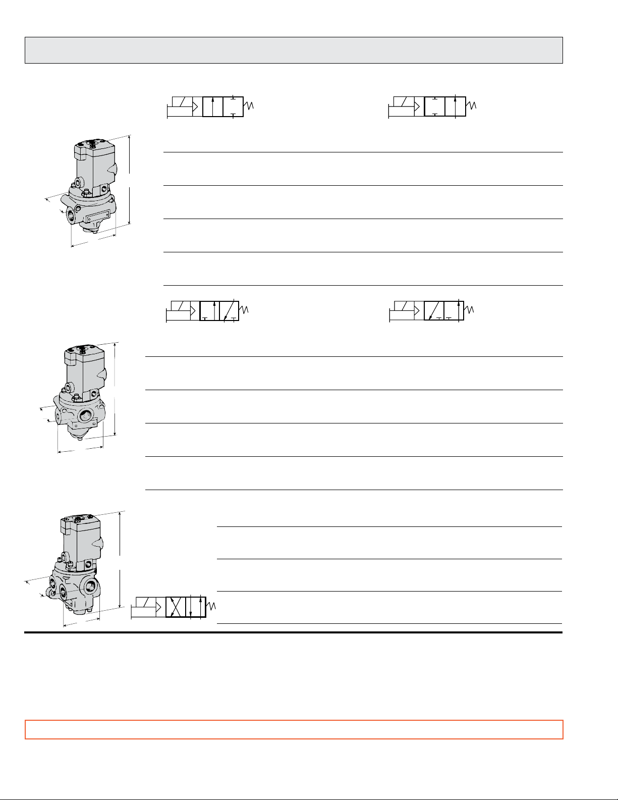
Series 27 Poppet Valves for Line Mounting
Single Solenoid Pilot Controlled
2/2 Valves
3/2 Valves
Normally Closed (NC) Normally Open (NO)
Port Valve Model Number Avg. C
Size NC NO NC NO A B C lb (kg)
Dimensions inches (mm)
V
Weight
1/4 2771B2001 2772B2001 2.3 2.3 3.6 (91) 3.2 (79) 6.9 (175) 2.5 (1.2)
3/8 2771B3001 2772B3001 3.8 3.3 3.6 (91) 3.2 (79) 6.9 (175) 2.5 (1.2)
1/2 2771B4011 2772B4011 4.0 3.5 3.6 (91) 3.2 (79) 6.9 (175) 2.5 (1.2)
1/2 2771B4001 2772B4001 7.7 6.5 4.6 (116) 3.2 (79) 7.6 (193) 3.3 (1.5)
3/4 2771B5001 2772B5001 9.0 7.3 4.6 (116) 3.2 (79) 7.6 (193) 3.3 (1.5)
1 2771B6011 2772B6011 9.0 7.9 4.6 (116) 3.2 (79) 7.6 (193) 3.3 (1.5)
1 2771B6001 2772B6001 24 21 6.7 (169) 4.1 (104) 10.4 (265) 7.0 (3.2)
1¼ 2771B7001 2772B7001 29 20 6.7 (169) 4.1 (104) 10.4 (265) 7.0 (3.2)
1½ 2771B8011 2772B8011 29 21 6.7 (169) 4.1 (104) 10.4 (265) 7.0 (3.2)
1½ 2771B8001 2772B8001 49 49 8.7 (219) 5.2 (131) 11.8 (300) 15.5 (6.9)
2 2771B9001 2772B9001 57 57 8.7 (219) 5.2 (131) 11.8 (300) 15.5 (6.9)
2½ 2771B9011 2772B9011 64 72 8.7 (219) 5.2 (131) 11.8 (300) 15.5 (6.9)
Normally Closed (NC) Normally Open (NO)
Port Sizes Valve Model Number Avg. CV Dimensions inches (mm)
Weight
In-Out Exh. NC NO NC NO A B C lb (kg)
1/4 1/2 2773B2001 2774B2001 2.8 2.5 3.6 (91) 3.2 (79) 7.2 (182) 2.5 (1.2)
3/8 1/2 2773B3001 2774B3001 4.0 3.0 3.6 (91) 3.2 (79) 7.2 (182) 2.5 (1.2)
1/2 1/2 2773B4011 2774B4011 3.8 3.0 3.6 (91) 3.2 (79) 7.2 (182) 2.5 (1.2)
1/2 1 2773B4001 2774B4001 7.8 7.2 4.6 (116) 3.6 (92) 7.9 (201) 3.3 (1.5)
3/4 1 2773B5001 2774B5001 9.4 7.2 4.6 (116) 3.6 (92) 7.9 (201) 3.3 (1.5)
1 1 2773B6011 2774B6011 10 7.2 4.6 (116) 3.6 (92) 7.9 (201) 3.3 (1.5)
1 1½ 2773B6001 2774B6001 29 21 6.7 (169) 4.9 (123) 10.4 (265) 7.0 (3.2)
1¼ 1½ 2773B7001 2774B7001 31 22 6.7 (169) 4.9 (123) 10.4 (265) 7.0 (3.2)
1½ 1½ 2773B8011 2774B8011 31 21 6.7 (169) 4.9 (123) 10.4 (265) 7.0 (3.2)
1½ 2½ 2773B8001 2774B8001 69 58 8.7 (219) 6.4 (161) 12.4 (313) 16.5 (7.4)
2 2½ 2773B9001 2774B9001 70 60 8.7 (219) 6.4 (161) 12.4 (313) 16.5 (7.4)
2½ 2½ 2773B9011 2774B9011 71 55 8.7 (219) 6.4 (161) 12.4 (313) 16.5 (7.4)
4/2 Valves
Port Sizes Valve Model Avg. Dimensions inches (mm) Weight
In-Out Exh. Number C
1/4 1/2 2776B2001 2.5 4.0 (100) 3.9 (97) 7.2 (182) 3.0 (1.4)
3/8 1/2 2776B3001 3.6 4.0 (100) 3.9 (97) 7.2 (182) 3.0 (1.4)
1/2 1/2 2776B4011 3.7 4.0 (100) 3.9 (97) 7.2 (182) 3.0 (1.4)
1/2 1 2776B4001 6.9 4.7 (118) 5.3 (135) 9.0 (228) 5.3 (2.4)
3/4 1 2776B5001 8.2 4.7 (118) 5.3 (135) 9.0 (228) 5.3 (2.4)
1 1 2776B6011 8.9 4.7 (118) 5.3 (135) 9.0 (228) 5.3 (2.4)
1 1½ 2776B6001 23 6.5 (166) 8.3 (211) 10.7 (271) 11.3 (5.1)
1¼ 1½ 2776B7001 24 6.5 (166) 8.3 (211) 10.7 (271) 11.3 (5.1)
1½ 1½ 2776B8011 25 6.5 (166) 8.3 (211) 10.7 (271) 11.3 (5.1)
STANDARD SPECIFICATIONS: For valves on this page.
Solenoids: AC or DC power.
Standard Voltages: Consult ROSS.
Power Consumption: 87 VA inrush, 30 VA holding on 50 or 60 Hz;
14 watts on DC.
Ambient Temperature: 40° to 120°F (4° to 50°C).
Media Temperature: 40° to 175°F (4° to 80°C).
IMPORTANT NOTE: Please read carefully and thoroughly all of the CAUTIONS on the inside back cover.
4 © 2009, ROSS CONTROLS®.
A B C lb (kg)
V
Flow Media: Filtered air; 5 micron recommended.
Inlet Pressure: 1/4 to 1½ Port Sizes: 15 to 150 psig (1 to 10 bar);
1½ to 2½ Port Sizes: 30 to 150 psig (2 to 10 bar).
Pilot Pressure: When external supply is used, pressure must be
equal to or greater than inlet pressure.
Threads: Model numbers above specify NPT pressure port threads.
For other threads, consult ROSS.
All Rights Reserved.
Page 2
B
A
C
B
A
C
B
A
C
1
2
3
4
14
1
2
3
12
1
2
10
3
1
2
10
1
2
12
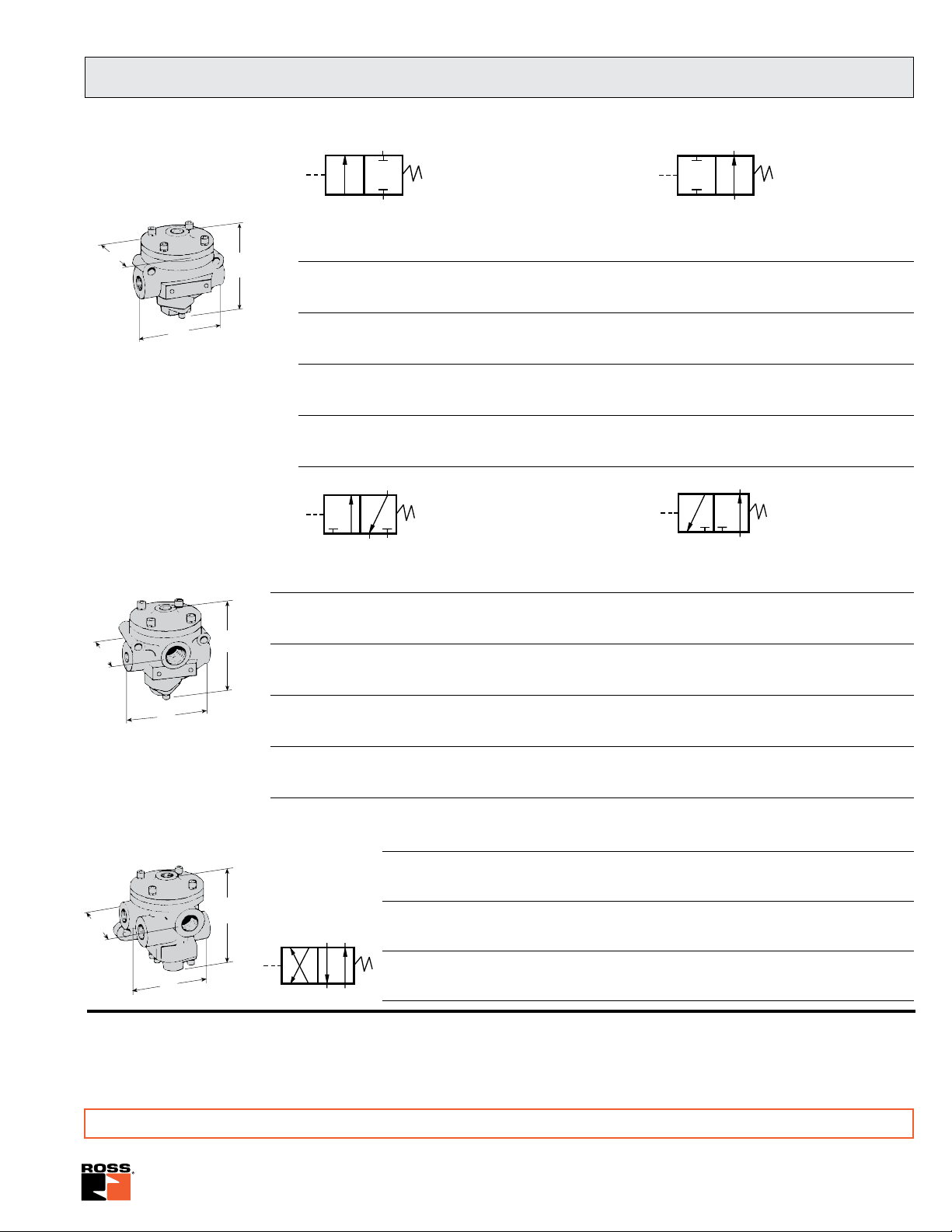
Series 27 Poppet Valves for Line Mounting
Single Pressure Controlled
2/2 Valves
3/2 Valves
Normally Closed (NC)
Port Valve Model Number Avg. CV Dimensions inches (mm)
Size NC NO NC NO A B C lb (kg)
1/4 2751A2001 2752A2001 2.3 2.3 3.6 (91) 3.2 (79) 3.8 (95) 1.3 (0.6)
3/8 2751A3001 2752A3001 3.8 3.3 3.6 (91) 3.2 (79) 3.8 (95) 1.3 (0.6)
1/2 2751A4011 2752A4011 4.0 3.5 3.6 (91) 3.2 (79) 3.8 (95) 1.3 (0.6)
1/2 2751A4001 2752A4001 7.7 6.5 4.6 (116) 3.2 (79) 4.5 (113) 2.0 (0.9)
3/4 2751A5001 2752A5001 9.0 7.3 4.6 (116) 3.2 (79) 4.5 (113) 2.0 (0.9)
1 2751A6011 2752A6011 9.0 7.9 4.6 (116) 3.2 (79) 4.5 (113) 2.0 (0.9)
1 2751A6001 2752A6001 24 21 6.7 (169) 4.1 (104) 7.5 (190) 8.0 (3.6)
1¼ 2751A7001 2752A7001 29 20 6.7 (169) 4.1 (104) 7.5 (190) 8.0 (3.6)
1½ 2751A8011 2752A8011 29 21 6.7 (169) 4.1 (104) 7.5 (190) 8.0 (3.6)
1½ 2751A8001 2752A8001 49 49 8.7 (219) 5.2 (131) 9.0 (228) 14.3 (6.4)
2 2751A9001 2752A9001 57 57 8.7 (219) 5.2 (131) 9.0 (228) 14.3 (6.4)
2½ 2751A9011 2752A9011 64 72 8.7 (219) 5.2 (131) 9.0 (228) 14.3 (6.4)
Normally Closed (NC)
Port Sizes Valve Model Number Avg. CV Dimensions inches (mm)
In-Out Exh. NC NO NC NO A B C lb (kg)
1/4 1/2 2753A2001 2754A2001 2.8 2.5 3.6 (91) 3.2 (79) 4.0 (101) 1.3 (0.6)
3/8 1/2 2753A3001 2754A3001 4.0 3.0 3.6 (91) 3.2 (79) 4.0 (101) 1.3 (0.6)
1/2 1/2 2753A4011 2754A4011 3.8 3.0 3.6 (91) 3.2 (79) 4.0 (101) 1.3 (0.6)
1/2 1 2753A4001 2754A4001 7.8 7.2 4.6 (116) 3.6 (92) 4.8 (121) 2.0 (0.9)
3/4 1 2753A5001 2754A5001 9.4 7.2 4.6 (116) 3.6 (92) 4.8 (121) 2.0 (0.9)
1 1 2753A6011 2754A6011 10 7.2 4.6 (116) 3.6 (92) 4.8 (121) 2.0 (0.9)
1 1½ 2753A6001 2754A6001 29 21 6.7 (169) 4.9 (123) 7.5 (190) 6.0 (2.7)
1¼ 1½ 2753A7001 2754A7001 31 22 6.7 (169) 4.9 (123) 7.5 (190) 6.0 (2.7)
1½ 1½ 2753A8011 2754A8011 31 21 6.7 (169) 4.9 (123) 7.5 (190) 6.0 (2.7)
1½ 2½ 2753A8001 2754A8001 69 58 8.7 (219) 6.4 (161) 9.5 (241) 15.3 (6.9)
2 2½ 2753A9001 2754A9001 70 60 8.7 (219) 6.4 (161) 9.5 (241) 15.3 (6.9)
2½ 2½ 2753A9011 2754A9011 71 55 8.7 (219) 6.4 (161) 9.5 (241) 15.3 (6.9)
Normally Open (NO)
Normally Open (NO)
Weight
Weight
4/2 Valves
STANDARD SPECIFICATIONS: For valves on this page.
Ambient/Media Temperature: 40° to 175°F (4° to 80°C).
Flow Media: Filtered air; 5 micron recommended.
Inlet Pressure: 1/4 to 1½ Port Sizes: 15 to 150 psig (1 to 10 bar).
1
½
to 2½ Port Sizes: 30 to 150 psig (2 to 10 bar).
Port Sizes Valve Model Avg. Dimensions inches (mm) Weight
In-Out Exh. Number C
1/4 1/2 2756A2001 2.5 4.0 (100) 3.9 (97) 4.0 (101) 1.8 (0.8)
3/8 1/2 2756A3001 3.6 4.0 (100) 3.9 (97) 4.0 (101) 1.8 (0.8)
1/2 1/2 2756A4011 3.7 4.0 (100) 3.9 (97) 4.0 (101) 1.8 (0.8)
1/2 1 2756A4001 6.9 4.7 (118) 5.3 (135) 5.8 (147) 4.3 (1.9)
3/4 1 2756A5001 8.2 4.7 (118) 5.3 (135) 5.8 (147) 4.3 (1.9)
1 1 2756A6011 8.9 4.7 (118) 5.3 (135) 5.8 (147) 4.3 (1.9)
1 1½ 2756A6001 23 6.5 (166) 8.3 (211) 7.5 (190) 10.3 (4.6)
1¼ 1½ 2756A7001 24 6.5 (166) 8.3 (211) 7.5 (190) 10.3 (4.6)
1½ 1½ 2756A8011 25 6.5 (166) 8.3 (211) 7.5 (190) 10.3 (4.6)
Pilot Pressure: Must be equal to or greater than inlet pressure.
Threads: Model numbers above specify NPT pressure port
threads. For other threads, consult ROSS.
A B C lb (kg)
V
IMPORTANT NOTE: Please read carefully and thoroughly all of the CAUTIONS on the inside back cover.
www.rosscontrols.com 5
Page 3

1
2
3
4
Y
12
14
Indicator
Light Kit
A
B
C
Series 27 Poppet Valves for Line Mounting
4/2 Valves – Double Direct Solenoid Controlled, Detented
Port Sizes Valve Model Avg. Dimensions inches (mm) Weight
In-Out Exh. Number C
1/4 1/2 2776B2003 2.5 9.3 (236) 3.9 (97) 7.9 (201) 4.0 (1.8)
3/8 1/2 2776B3003 3.6 9.3 (236) 3.9 (97) 7.9 (201) 4.0 (1.8)
1/2 1/2 2776B4013 3.7 9.3 (236) 3.9 (97) 7.9 (201) 4.0 (1.8)
1/2 1 2776B4003 6.9 9.3 (236) 5.3 (135) 9.7 (246) 6.3 (2.8)
3/4 1 2776B5003 8.2 9.3 (236) 5.3 (135) 9.7 (246) 6.3 (2.8)
1 1 2776B6013 8.9 9.3 (236) 5.3 (135) 9.7 (246) 6.3 (2.8)
1 1½ 2776B6003 23 9.3 (236) 8.3 (211) 11.6 (295) 12.3 (5.5)
1¼ 1½ 2776B7003 24 9.3 (236) 8.3 (211) 11.6 (295) 12.3 (5.5)
1½ 1½ 2776B8013 25 9.3 (236) 8.3 (211) 11.6 (295) 12.3 (5.5)
A B C lb (kg)
V
STANDARD SPECIFICATIONS: For valves listed above.
Solenoids: AC or DC power.
Standard Voltages: Consult ROSS.
Power Consumption: Each solenoid; 190 VA inrush, 40 VA
holding on 50 or 60 Hz; 20 watts on DC.
Inlet Pressure: 15 to 150 psig (1 to 10 bar).
Pilot Pressure: If external supply is used, pressure must
be equal to or greater than inlet pressure.
Threads: Model numbers above specify NPT pressure port
threads. For other threads, consult ROSS.
Indicator Lights: In each solenoid housing.
Ambient Temperature: 40° to 120°F (4° to 50°C).
Media Temperature: 40° to 175°F (4° to 80°C).
Flow Media: Filtered air; 5 micron recommended.
Please read carefully and thoroughly
all of the CAUTIONS on the inside back cover.
IMPORTANT NOTE
Indicator Light Kit Manual Override Kits
Flush flexible manual overrides are standard on single
solenoid models in Series 16 and Series 27. Double solenoid
models in Series 21 and 27 have flush metal-button overrides.
Both types are non-locking.
Each of the buttons in the override kits below is made of metal
and is spring-returned. The locking type button, however,
can be kept in the actuated position by turning the slot in the
top of the button with a screwdriver.
Order by the kit numbers shown below.
FLUSH BUTTON
Locking type ................Kit 792K87
Non-locking type ..........Kit 790K87
An indicator light extends through the solenoid or pilot
cover and is illuminated when the solenoid is energized.
Such lights are standard on double solenoid valves in
Series 21 and 27.
An indicator light is available in kit form for single solenoid
models in Series 16, Series 21 (type O only), and Series 27.
Order kit number 862K87 and specify the voltage of the
solenoid.
6 © 2009, ROSS CONTROLS®.
EXTENDED BUTTON
Non-locking type.......Kit 791K87
All Rights Reserved.
EXTENDED BUTTON
WITH PALM ACTUATOR
Non-locking type......Kit 984H87
 Loading...