

Page 1
Ports: 1/8 & 1/4
A
Flow to 22 scfm
120
80
68
4
10
16
0
40
2
12
0
14
2
00
BAR
0
100 x kPa
psi
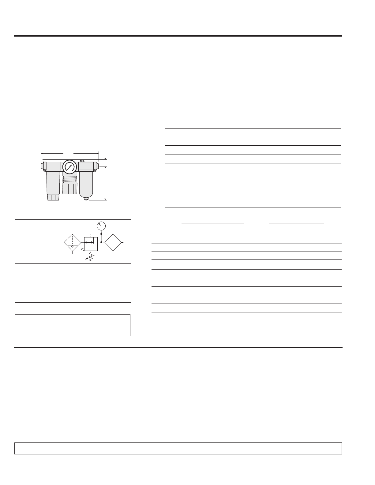
BANTAM Modular FRLs
FEATURES:
• Individual lter, piston-type regulator or diaphragm-type, wick-feed lubricator
• Modular assembly and mounting
• Threaded ports or quick-connect ttings for tubing up to 10 mm in diameter
• 5-micron rated polyethylene lter element
• High-strength polycarbonate plastic bowls or aluminum bowls
• Internal automatic lter drain; optional manual drain
• Self-relieving regulator; optional non-relieving
• Pressure gauge
Port
Size A B C Depth lb (kg)
C
1/8, 1/4 6.3 (160) 3.6 (92) 1.7 (43) 3.6 (92) 0.53 (0.24)
Models below have quick-connect fittings for tubing.
1/4 6.7 (170) 3.6 (92) 1.7 (43) 3.6 (92) 0.50 (0.23)
3/8 7.2 (183) 3.6 (92) 1.7 (43) 3.6 (92) 0.50 (0.23)
B
4 mm 6.7 (170) 3.6 (92) 1.7 (43) 3.6 (92) 0.50 (0.23)
6 mm 6.7 (170) 3.6 (92) 1.7 (43) 3.6 (92) 0.50 (0.23)
8 mm 6.4 (163) 3.6 (92) 1.7 (43) 3.6 (92) 0.50 (0.23)
10 mm 7.2 (183) 3.6 (92) 1.7 (43) 3.6 (92) 0.50 (0.23)
DIMENSIONS inches (mm)
Weight
Port Automatic Drain Models Manual Drain Models
ISO Symbol
FRL
1
2
Automatic Drain
Self-relieving
REPLACEMENT FILTER ELEMENT KIT
Element Rating/Type Kit Number
0.5 µm polyethylene - Standard 933K77
AIR FLOW DATA
See Flow Charts for individual assembly
components on preceding pages.
STANDARD SPECIFICATIONS (for products on this page):
Ambient/Media Temperature:
Polycarbonate plastic bowl: 40° to 125°F (4° to 52°C).
Metal bowls: 40° to 175°F (4° to 79°C).
Bodies: Acetal.
Bowls: 2-ounce (60-ml) capacity polycarbonate plastic bowls or
aluminum bowls.
Filter Drain: Internal automatic drain; optional manual drain.
Filter Element: 5-micron rated polyethylene.
Fluid Media: Compressed air.
Size Plastic Bowl Metal Bowl Plastic Bowl Metal Bowl
THREADED
1/8 5B01C0115 5B01C0216 5B01C0315 5B01C0416
1/4 5B02C0115 5B02C0216 5B02C0315 5B02C0416
TUBE FITTINGS
1/4 5B03C0115 5B03C0216 5B03C0315 5B03C0416
3/8 5B04C0115 5B04C0216 5B04C0315 5B04C0416
4mm 5B05C0115 5B05C0216 5B05C0315 5B05C0416
6mm 5B06C0115 5B06C0216 5B06C0315 5B06C0416
8mm 5B07C0115 5B07C0216 5B07C0315 5B07C0416
10mm 5B08C0115 5B08C0216 5B08C0315 5B08C0416
For quick fill cap on lubricator, change the last digit to a seven (7), e.g., 5B08C0216
becomes 5B08C0217.
For diaphragm regulator, change eighth digit to a two (2), e.g., 5B01C0115 becomes
5B01C0125.
IMPORTANT NOTE: Please read carefully and thoroughly all of the CAUTIONS on the inside back cover.
PISTON TYPE
Inlet Pressure:
For automatic drain model:
With polycarbonate plastic bowl: 15 to 150 psig (1.0 to 10.3 bar).
With metal bowl: 15 to 200 psig (1.0 to 13.8 bar).
For manual drain model:
With polycarbonate plastic bowl: 0 to 150 psig (0 to 10.3 bar).
With metal bowl: 0 to 200 psig (0 to 13.8 bar).
Oil Adjustment: External, no shutoff.
Outlet Pressure: Adjustable up to 100 psig (6.9 bar).
Panel Mounting: 1-3/16 inch (30 mm) hole required.
Regulator Dome and Knob: Acetal.
Seals: Nitrile.
Threads: NPT standard, BSPP. For BSPP threads, add a “C” prefix
to the model number, e.g., C5B01C0115.
68 © 2012, ROSS CONTROLS.
All Rights Reserved.
Page 2
Ports: 1/8 & 1/4
A
Flow to 19 scfm
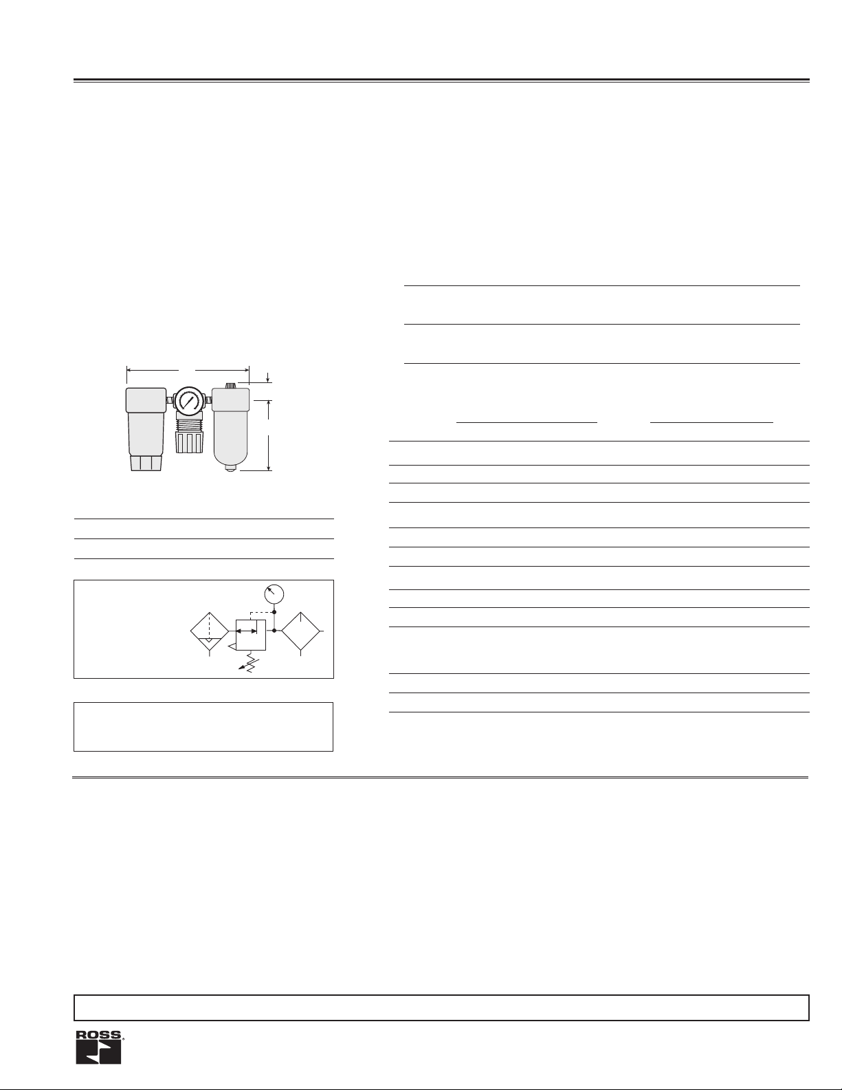
MINIATURE FRLs
FEATURES:
• Individual lter, piston-type or diaphragm-type regulator, wick-feed lubricator
• Inline mounting
• 5-micron rated polyethylene lter element
• High-strength polycarbonate plastic bowls or aluminum bowls
• Internal automatic lter drain; optional manual drain
• Self-relieving regulator; optional non-relieving
• Pressure gauge
120
80
68
4
10
1
60
0
4
2
12
0
14
2
0
BAR
0
0
100 x kPa
psi
C
B
REPLACEMENT FILTER ELEMENT KIT
Element Rating/Type Kit Number
0.5 µm polyethylene (Std. element) 933K77
ISO Symbol
FRL
1
2
Automatic Drain
Self-relieving
AIR FLOW DATA
See Flow Charts for individual assembly
components on preceding pages.
DIMENSIONS inches (mm)*
Weight †
Bowl A B C Depth † lb (kg)
Plastic 5.5 (140) 3.6 (90) 0.7 (17) 1.6 (41) 0.76 (0.34)
Metal 5.5 (140) 4.3 (109) 0.7 (17) 1.6 (41) 0.76 (0.34)
* Dimensions do not include pressure gauges.
† Less gauge.
Port Automatic Drain Models Manual Drain Models
Size Plastic Bowl Metal Bowl Plastic Bowl Metal Bowl
COMBINATION FILTER & REGULATOR* (diaphragm type)
1/8 5321C1027 5322C1024 5321C1026 5322C1025
1/4 5321C2027 5322C2024 5321C2026 5322C2025
COMBINATION FILTER & REGULATOR* (diaphragm type)
1/8 5321C1037 5322C1034 5321C1036 5322C1035
1/4 5321C2037 5322C2034 5321C2036 5322C2035
COMBINATION FILTER & LUBRICATOR ** (High flow)
1/8 5311C1012 5312C1012 5311C1011 5312C1011
1/4 5311C2012 5312C2012 5311C2011 5312C2011
1/8 5331C1006 5332C1006 5331C1005 5332C1005
1/4 5331C2006 5332C2006 5331C2005 5332C2005
*Regulated pressure 0 – 100 psig (0 - 6.9 bar); gauge included.
**To order the lubricator with a quick-fill cap, change the third digit from the end of
the model number from “0” to “1,” e.g., model 5311C1012 with quick-fill cap becomes
model 5311C1112.
COMBINATION FILTER, REGULATOR*
(diaphragm type) & LUBRICATOR** (High flow)
STANDARD SPECIFICATIONS (for products on this page):
Ambient/Media Temperature:
Polycarbonate plastic bowl: 40° to 125°F (4° to 52°C).
Metal bowls: 40° to 175°F (4° to 79°C).
Bowls: 2-ounce (60-ml) capacity polycarbonate plastic bowls or
aluminum bowls.
Filter Drain: Internal automatic drain; optional manual drain.
Filter Element: 5-micron rated polyethylene.
Fluid Media: Compressed air.
Heads: Aluminum.
Inlet Pressure:
For automatic drain model:
With polycarbonate plastic bowl: 15 to 150 psig (1.0 to 10.3 bar).
With metal bowl: 15 to 200 psig (1.0 to 13.8 bar).
Inlet Pressure:
For manual drain model:
With polycarbonate plastic bowl: 0 to 150 psig (0 to 10.3 bar).
With metal bowl: 0 to 200 psig (0 to 13.8 bar).
Oil Adjustment: Internal; tamper-resistant.
Outlet Pressure: Adjustable up to 100 psig (6.9 bar).
Pressure Gauge: 0 to 160 psig (0 to 11.0 bar); 1/8 NPT gauge
ports front and rear.
Panel Mounting: 1-3/16 inch (30 mm) hole required.
Regulator Dome and Knob: Acetal.
Seals: Nitrile.
Threads: NPT standard, BSPP. For BSPP threads, add a “C” prefix
to the model number, e.g., C5321C1027.
IMPORTANT NOTE: Please read carefully and thoroughly all of the CAUTIONS on the inside back cover.
www.rosscontrols.com 69
Page 3

Ports: 1/4, 3/8, 1/2
A
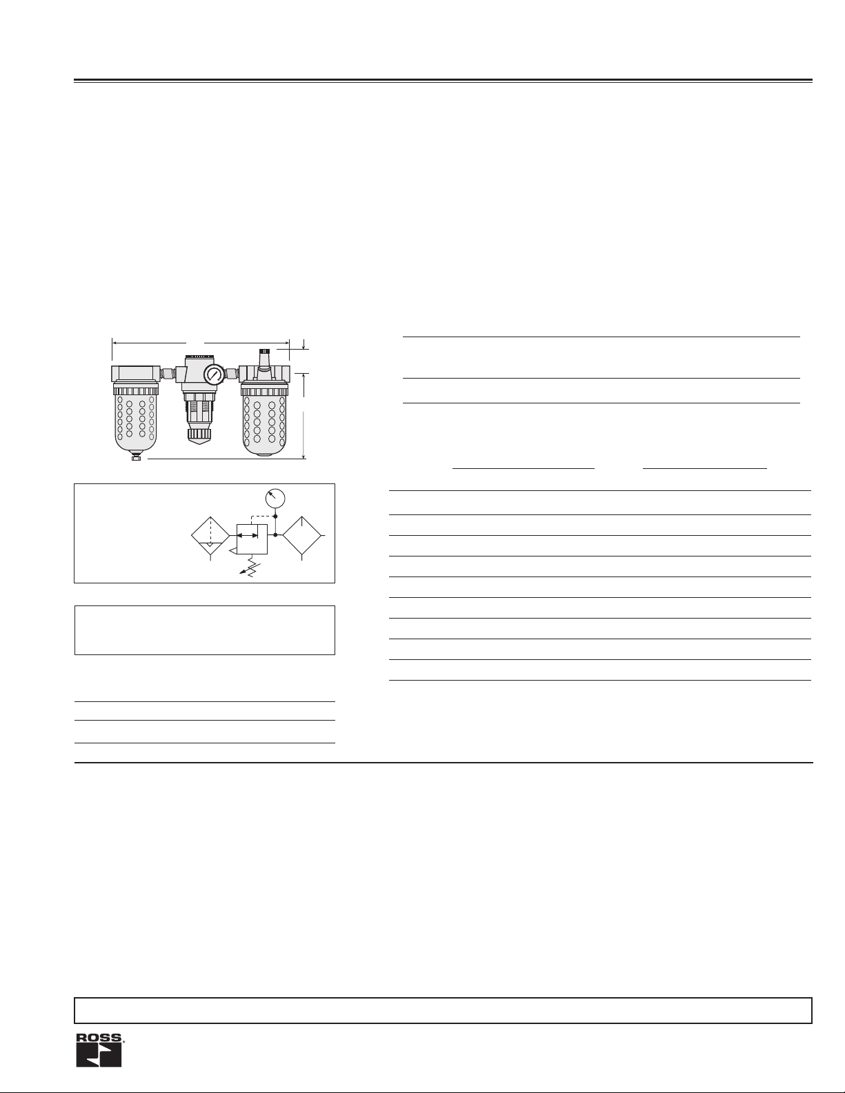
MID-SIZE Modular FRLs
FEATURES:
• Individual lter, piston-type regulator, sight-feed lubricator
• Modular or inline mounting
• 5-micron rated polyethylene lter element
• High-strength zinc bowl or polycarbonate plastic bowl with shatterguard
• Internal automatic lter drain; optional manual drain
• Self-relieving regulator; optional non-relieving
• Pressure gauge
120
0
8
68
4
10
160
40
2
12
0
14
200
BAR
0
100 x kPa
psi
C
B
ISO Symbol
FRL
1
2
Automatic Drain
Self-relieving
REPLACEMENT FILTER ELEMENT KIT
Element Rating/Type Kit Number
0.5 µm polyethylene (Std. element) 936K77
AIR FLOW DATA
See Flow Charts for individual assembly
components on preceding pages.
DIMENSIONS inches (mm)
Weight
Bowl A B C Depth † lb (kg)
Plastic 8.5 (215) 4.6 (117) 1.8 (46) 2.8 (71) 3.75 (1.70)
Metal 8.5 (215) 4.7 (119) 1.8 (46) 2.8 (71) 3.75 (1.70)
† Less gauge.
Port Automatic Drain Models Manual Drain Models
Size Plastic Bowl** Metal Bowl Plastic Bowl** Metal Bowl
COMBINATION FILTER & REGULATOR* (Includes 2 female port kits.)
1/4 5M11B2110 5M11B2210 5M11B2310 5M11B2410
3/8 5M11B3110 5M11B3210 5M11B3310 5M11B3410
1/2 5M11B4110 5M11B4210 5M11B4310 5M11B4410
COMBINATION FILTER & LUBRICATOR (Includes 2 female port kits.)
1/4 5M11B2101 5M11B2202 5M11B2301 5M11B2402
3/8 5M11B3101 5M11B3202 5M11B3301 5M11B3402
1/2 5M11B4101 5M11B4202 5M11B4301 5M11B4402
1/4 5M11B2111 5M11B2212 5M11B2311 5M11B2412
3/8 5M11B3111 5M11B3212 5M11B3311 5M11B3412
1/2 5M11B4111 5M11B4212 5M11B4311 5M11B4412
*Piston type; regulated pressure 0-100 psig (0-6.9 bar); gauge included.
**Plastic bowl includes metal bowl guard.
Note: Each regulator comes complete with a gauge.
COMBINATION FILTER, REGULATOR* & LUBRICATOR
(Includes 2 female port kits.)
STANDARD SPECIFICATIONS (for products on this page):
Ambient/Media Temperature:
Polycarbonate plastic bowl: 40° to 125°F (4° to 52°C).
Metal bowls: 40° to 175°F (4° to 79°C).
Bowls: 4-ounce (120-ml) capacity zinc bowls or polycarbonate
plastic bowls with zinc shatterguards.
Filter Drain: Internal automatic drain; optional manual drain.
Filter Element: 5-micron rated polyethylene.
Fluid Media: Compressed air.
Heads: Zinc.
Inlet Pressure:
For automatic drain model:
With polycarbonate plastic bowl: 15 to 150 psig (1.0 to 10.3 bar).
With metal bowl: 15 to 200 psig (1.0 to 13.8 bar).
Inlet Pressure:
For manual drain model:
With polycarbonate plastic bowl: 0 to 150 psig (0 to 10.3 bar).
With metal bowl: 0 to 200 psig (0 to 13.8 bar).
Oil Adjustment: External; tamper-resistant.
Outlet Pressure: Adjustable up to 100 psig (6.9 bar).
Pressure Gauge: 0 to 200 psig (0 to 14 bar); 1/4 NPT gauge ports
front and rear.
Panel Mounting: 1-9/16 inch (40 mm) hole required.
Regulator Dome and Knob: Acetal. Optional metal regulator dome.
Seals: Nitrile.
Sight Dome: Clear nylon.
Threads: NPT standard, BSPP, SAE. For BSPP threads, add a
“C” prefix to the model number, e.g., C5M11B2110.
IMPORTANT NOTE: Please read carefully and thoroughly all of the CAUTIONS on the inside back cover.
70 © 2012, ROSS CONTROLS.
All Rights Reserved.
Page 4

FULL-SIZE FRLs
Ports: 1/4, 3/8, 1/2, 3/4
Flow to 138 scfm
A
12
0
80
68
4
10
1
6
0
0
4
2
12
0
14
200
BAR
0
100 x kPa
psi
REPLACEMENT FILTER ELEMENT KIT
Element Rating/Type Kit Number
0.5 µm polyethylene (Std. element) 939K77
ISO Symbol
FRL
1
Automatic Drain
Self-relieving
AIR FLOW DATA
See Flow Charts for individual assembly
components on preceding pages.
C
B
FEATURES:
• Individual lter, diaphragm-type regulator, sight-feed lubricator
• Modular or inline mounting
• 5-micron rated polyethylene lter element
• Zinc bowl with clear nylon sight glass or polycarbonate plastic bowl with
steel shatterguard
• Internal automatic lter drain; optional manual drain or electronic drain
• Self-relieving regulator; optional non-relieving
• Pressure gauge
DIMENSIONS inches (mm)
Weight †
Bowl A B C Depth † lb (kg)
8-oz Plastic 10.1 (256) 5.8 (147) 1.3 (33) 2.8 (71) 7.06 (3.20)
8-oz Metal 10.1 (256) 6.4 (163) 1.3 (33) 2.8 (71) 7.06 (3.20)
† Less gauge.
Port Automatic Drain Models Manual Drain Models
Size Plastic Bowl** Metal Bowl Plastic Bowl** Metal Bowl
COMBINATION FILTER & REGULATOR* (Includes 2 female port kits.)
1/4 5F11B2120 5F11B2220 5F11B2320 5F11B2420
3/8 5F11B3120 5F11B3220 5F11B3320 5F11B3420
1/2 5F11B4120 5F11B4220 5F11B4320 5F11B4420
3/4 5F11B5120 5F11B5220 5F11B5320 5F11B5420
COMBINATION FILTER & LUBRICATOR (Includes 2 female port kits.)
1/4 5F11B2101 5F11B2202 5F11B2301 5F11B2402
3/8 5F11B3101 5F11B3202 5F11B3301 5F11B3402
1/2 5F11B4101 5F11B4202 5F11B4301 5F11B4402
3/4 5F11B5101 5F11B5202 5F11B5301 5F11B5402
2
1/4 5F11B2121 5F11B2222 5F11B2321 5F11B2422
3/8 5F11B3121 5F11B3222 5F11B3321 5F11B3422
1/2 5F11B4121 5F11B4222 5F11B4321 5F11B4422
3/4 5F11B5121 5F11B5222 5F11B5321 5F11B5422
*Piston type; regulated pressure 0-100 psig (0-6.9 bar); gauge included.
**Plastic bowl includes metal bowl guard.
For pipe nipple version, change the third and fourth digit to zero (0),
e.g., 5F11B2321 becomes 5F00B2321.
COMBINATION FILTER, REGULATOR* & LUBRICATOR
(Includes 2 female port kits.)
STANDARD SPECIFICATIONS (for products on this page):
Ambient/Media Temperature:
Polycarbonate plastic bowl: 40° to 125°F (4° to 52°C).
Metal bowls: 40° to 175°F (4° to 79°C).
Bowls: 8-ounce (240-ml) capacity zinc bowl with clear n ylon sight
glass or polycarbonate plastic bowl with steel shatterguard.
Bowl Rings: Aluminum.
Filter Drain: Internal automatic drain; optional manual drain or
electronic drain.
Filter Element: 5-micron rated polyethylene.
Fluid Media: Compressed air.
Heads: Zinc.
Inlet Pressure:
For automatic drain model:
Inlet Pressure:
For manual drain model:
With polycarbonate plastic bowl: 0 to 150 psig (0 to 10.3 bar).
With metal bowl: 0 to 200 psig (0 to 13.8 bar).
Oil Adjustment: External; tamper-resistant.
Outlet Pressure: Adjustable up to 125 psig (8.6 bar).
Pressure Adjustment Locking Key: Removable.
Pressure Gauge: 0 to 200 psig (0 to 14 bar); 1/4 NPT gauge
ports front and rear.
Regulator: Nylon dome; acetal knob.
Seals: Nitrile.
Sight Dome: Clear nylon.
Threads: NPT standard, BSPP, SAE. For BSPP threads, add a
“C” prefix to the model number, e.g., C5F11B2120.
With polycarbonate plastic bowl: 15 to 150 psig (1.0 to 10.3 bar).
With metal bowl: 15 to 200 psig (1.0 to 13.8 bar).
IMPORTANT NOTE: Please read carefully and thoroughly all of the CAUTIONS on the inside back cover.
www.rosscontrols.com 71
Page 5

Ports: 3/8, 1/2, 3/4
Flow to 205 scfm
MD4TM FRLs
A
12
0
0
8
68
4
10
1
60
0
4
2
12
0
14
2
0
BAR
0
0
100 x kPa
psi
Metal Bowls
C
B
FEATURES:
• Individual lter, regulator, lubricator
• Modular or inline mounting
• 5-micron rated polyethylene lter element; optional 40-micron
element
• Aluminum bowl with clear nylon sight glass or polycarbonate
plastic bowl with steel shatterguard
• Internal automatic lter drain; optional manual or electronic drain
• Optional extended aluminum lubricator bowl with sight glass
• Self-relieving diaphragm-type regulator; optional non-relieving
• Pressure gauge; two gauge ports
ISO Symbol - FRL
Automatic Drain - Self-relieving
1
2
A
12
0
80
68
4
10
1
60
40
2
12
0
14
200
BAR
0
100 x kPa
psi
Bowl A B* C Depth † lb (kg)
C
DIMENSIONS inches (mm)
9 oz Plastic 10.9 (276) 7.7 (195) 2.2 (56) 2.9 (73) 6.94 (3.15)
9 oz Metal 10.9 (276) 7.6 (193) 2.2 (56) 3.1 (79) 6.94 (3.15)
15 oz Metal 10.9 (276) 10.6 (269) 2.2 (56) 3.1 (79) 7.13 (3.24)
B
* Bowl removal clearance: For 9-ounce bowls add 3.4 (86).
For extended bowl add 6.1 (155).
† Less gauge.
Extended Metal
Lubricator Bowl
AIR FLOW DATA
See Flow Charts for individual assembly components on preceding pages.
REPLACEMENT FILTER ELEMENT KIT
Element Rating/Type Kit Number
0.5-µm polyethylene - Standard R-A115-106PE5
40-µm bronze R-A115-106PE3
HOW T O ORDER
MD4 53P B A 5 5 2 S *
BOWL SIZE
53P - Two 9 oz Polycarbonate Bowls
53M - Two 9 oz Metal Bowls
53E - 9 oz metal bowl on filter
15 oz metal bowl on lubricator
53F - 9 oz polycarbonate bowl on filter
15 oz metal bowl on lubricator
FILTER
ELEMENT TYPE
A - 40-µm
B - 5-µm (standard)
REGULATOR ADJUSTMENT RANGE
A - 0-175 psig (0-12.1 bar) with 0-200 psig (0-13.8 bar) gauge
B - 0-125 psig (0-8.6 bar) standard with 0-200 psig (0-13.8 bar) gauge
C - 0-50 psig (0-3.4 bar) with 0-60 psig (0-4.1 bar) gauge
D - 0-20 psig (0-1.3 bar) with 0-60 psig (0-4.1 bar) gauge
E - no regulator with 0-60 psig (0-4.1 bar) gauge
For mounting bracket options, see page 77.
B
PIPE SIZE
3 - 3/8 NPTF
4 - 1/2 NPTF
5 - 3/4 NPTF
C - 3/8 BSPP
D - 1/2 BSPP
E - 3/4 BSPP
F - 3/4-16 SAE
G - 7/8-14 SAE
FIL TER REGULA TOR TYPE
5 - Side by side (two piece) with auto drain
6 - Side by side (two piece) with manual drain
7 - Side by side (two piece) with electronic drain - manual drain only
8 - Side by side (two piece) with automatic external drain - manual drain only
LUBRICA TOR TYPE
S - Standard
Q - Quick-Fill Cap
N - No Lubricator
COLOR
G - Gray
Y - Yellow
R - Red
B - Blue
2 - Gold (standard)
ADD ON L-O-X
Weight †
®
1 - Outlet Side
2 - Inlet Side
3 - L-O-X
®
with EEZ-ON
on Outlet Side
4 - L-O-X® with EEZ-ON®
on Inlet Side
- Blank for no L-O-X®
®
STANDARD SPECIFICATIONS (for products on this page):
Ambient/Media Temperature:
Polycarbonate plastic bowl: 40° to 125°F (4° to 52°C).
Metal bowls: 40° to 175°F (4° to 79°C).
Bowls: 9-ounce (270-ml) capacity aluminum bowl with clear nylon
sight glass or polycarbonate plastic bowl with steel shatterguard.
Optional 15-ounce (450-ml) extended aluminum lubricator bowl with
two clear nylon sight glasses.
Bowl Rings: Nylon.
Cap Color: Gold standard; optional gray, yellow, red, blue.
Filter Drain: Internal automatic drain; optional manual drain or
electronic drain.
Filter Element: 5-micron rated polyeth ylene; optional 40-micron element.
Fluid Media: Compressed air.
Heads: Zinc.
Inlet Pressure:
For automatic drain model:
With polycarbonate plastic bowl: 15 to 150 psig (1.0 to 10.3 bar).
With metal bowl: 15 to 200 psig (1.0 to 13.8 bar).
For manual drain model:
With polycarbonate plastic bowl: 0 to 150 psig (0 to 10.3 bar).
With metal bowl: 0 to 200 psig (0 to 13.8 bar).
Oil Adjustment: External; tamper-resistant.
Outlet Pressure: Adjustable up to 125 psig (8.6 bar).
Pressure Adjustment Locking Key: Removable.
Pressure Gauge: 0 to 200 psig (0 to 14 bar); 1/4 NPT gauge
ports front and rear.
Seals: Nitrile.
Sight Dome: Clear nylon.
Threads: NPT standard, BSPP, SAE.
IMPORTANT NOTE: Please read carefully and thoroughly all of the CAUTIONS on the inside back cover.
72 © 2012, ROSS CONTROLS.
All Rights Reserved.
Page 6
Ports: 3/4 & 1
A
Flow to 270 scfm
HIGH-CAPACITY FRLs
FEATURES:
• Individual lter, piston-type regulator, wick-feed lubricator
• Inline mounting
• 5-micron rated polyethylene lter element
• Metal bowls with clear nylon sight glass or polycarbonate plastic bowls
with steel shatterguard
• Internal automatic lter drain, optional manual drain, external automatic
drain, or electronic drain
• Self-relieving regulator; optional non-relieving
• Pressure gauge
12
0
80
68
4
10
160
40
2
12
0
14
20
BAR
0
0
100 x kPa
psi
C
B
ISO Symbol
FRL
1
Automatic Drain
Self-relieving
AIR FLOW DATA
See Flow Charts for individual assembly
components on preceding pages.
REPLACEMENT FILTER ELEMENT KIT
Element Rating/Type Kit Number
0.5-µm polyethylene (Std. element) 1010K77
DIMENSIONS inches (mm)*
Weight
A B C Depth lb (kg)
15.8 (401) 8.0 (204) 1.2 (31) 4.3 (108) 8.00 (3.64)
*Dimensions do not include pressure gauges.
Port Automatic Drain Models Manual Drain Models
Size Plastic Bowl** Metal Bowl Plastic Bowl** Metal Bowl
COMBINATION FILTER & REGULATOR*
2
3/4 5H00C5110 5H00C5210 5H00C5310 5H00C5410
1 5H00C6110 5H00C6210 5H00C6310 5H00C6410
COMBINATION FILTER & LUBRICATOR
3/4 5H00B5101 5H00B5202 5H00B5301 5H00B5402
1 5H00B6101 5H00B6202 5H00B6301 5H00B6402
COMBINATION FILTER, REGULATOR* & LUBRICATOR
3/4 5H00C5111 5H00C5212 5H00C5311 5H00C5412
1 5H00C6111 5H00C6212 5H00C6311 5H00C6412
*Piston type; regulated pressure 0-100 psig (0-6.9 bar); gauge included.
**Plastic bowl includes metal bowl guard.
Note: Each regulator comes complete with a gauge.
Note: For BSPP threads, add the letter “C” in front of the part number.
STANDARD SPECIFICATIONS (for products on this page):
Ambient/Media Temperature:
Polycarbonate plastic bowl: 40° to 125°F (4° to 52°C).
Metal bowls: 40° to 175°F (4° to 79°C).
Bowls: 16-ounce (480-ml) capacity aluminum bowls with sight glass
or polycarbonate plastic bowls with steel shatterguard.
Bowl Rings: Aluminum.
Filter Drain: Internal automatic drain; optional manual drain,
external automatic, or electronic drain.
Filter Element: 5-micron rated polyethylene.
Fluid Media: Compressed air.
Heads: Aluminum.
Inlet Pressure:
For automatic drain model:
With polycarbonate plastic bowl: 15 to 150 psig (1.0 to 10.3 bar).
With metal bowl: 15 to 200 psig (1.0 to 13.8 bar).
For manual drain model:
With polycarbonate plastic bowl: 0 to 150 psig (0 to 10.3 bar).
With metal bowl: 0 to 200 psig (0 to 13.8 bar).
Oil Adjustment: External; tamper-resistant.
Outlet Pressure: Adjustable up to 100 psig (6.9 bar).
Pressure Adjustment Locking Key: Removable.
Pressure Gauge: 0 to 200 psig (0 to 14 bar);
1/4 NPT gauge ports front and rear.
Seals: Nitrile.
Threads: NPT standard, BSPP . For BSPP threads, add a “C” prefix
to the model number, e.g., C5H00C5110.
IMPORTANT NOTE: Please read carefully and thoroughly all of the CAUTIONS on the inside back cover.
www.rosscontrols.com 73
Page 7

Ports: 1¼ & 1½
A
Flow to 495 scfm
12
0
80
68
4
10
1
60
0
4
2
12
0
14
200
BAR
0
100 x kPa
psi
See Flow Charts for individual assembly
AIR FLOW DATA
components on preceding pages.
HIGH-CAPACITY FRLs
FEATURES:
• Individual lter, piston-type regulator, sight-feed
• Inline mounting
• 5-micron rated lter element; optional 40-micron lter element
• Aluminum bowls with clear nylon sight glass
• Internal automatic lter drain; optional manual drain
• Self-relieving regulator
• Pressure gauge
ISO Symbol
Automatic Drain
Self-relieving
C
DIMENSIONS inches (mm)
B
A B* C Depth lb (kg)
15.8 (401) 10.6 (268) 2.1 (54) 4.3 (108) 8.00 (3.64)
REPLACEMENT FILTER ELEMENT KIT
Element Rating/Type Kit Number
0.5-µm polyethylene - Standard 1656K77
40-µm bronze - Optional R-A114-106E3
FRL
1
Weight
2
HOW T O ORDER
HIGH-CAPACITY Model No. 5H 00C
PIPE SIZE
7 = 1¼
8 = 1½
STANDARD SPECIFICATIONS (for products on this page):
Ambient/Media Temperature:
Polycarbonate plastic bowl: 40° to 125°F (4° to 52°C).
Metal bowls: 40° to 175°F (4° to 79°C).
Bowls: 35-ounce (1 liter) capacity aluminum bowls with clear nylon
sight glasses.
Bowl Rings: Aluminum.
Filter Drain: Internal automatic drain. Optional manual drain.
Filter Element: 5-micron or 40-micron rated filter element availab le.
Fluid Media: Compressed air.
Heads: Aluminum.
Inlet Pressure:
For automatic drain model:
With polycarbonate plastic bowl: 15 to 150 psig (1.0 to 10.3 bar).
With metal bowl: 15 to 200 psig (1.0 to 13.8 bar).
FILTER
0 = None
1 = Automatic drain, metal bowl, 40 micron
2 = Automatic drain, metal bowl, 5 micron
3 = Manual drain, metal bowl, 40 micron
4 = Manual drain, metal bowl, 5 micron
NOTE: Polycarbonate plastic bowls for 1¼ and 1½ units not available.
* * * *
LUBRICATOR
0 = None
2 = Sight-feed, metal bowl
4 = Sight-feed, metal bowl, quick-fill cap
REGULATOR
0 = None
1 = Piston, 0-100 psig (0-6.9 bar)
8 = Internal pilot, 15-200 psig (1.0-13.8 bar)
Inlet Pressure:
For manual drain model:
With polycarbonate plastic bowl: 0 to 150 psig (0 to 10.3 bar).
With metal bowl: 0 to 200 psig (0 to 13.8 bar).
Oil Adjustment: External; tamper-resistant.
Outlet Pressure: Adjustable up to 100 psig (6.9 bar).
Pressure Adjustment Locking Key: Removable.
Pressure Gauge: 0 to 200 psig (0 to 14 bar); 1/4 NPT gauge
ports front and rear.
Regulator: Nylon dome; acetal knob.
Seals: Nitrile.
Sight Dome: Clear nylon.
Threads: NPT standard, BSPP. For BSPP threads, add a “C” prefix
to the model number, e.g., C5H00C7112.
IMPORTANT NOTE: Please read carefully and thoroughly all of the CAUTIONS on the inside back cover.
74 © 2012, ROSS CONTROLS.
All Rights Reserved.
Page 8

Components for Modular Assembly
MID-SIZE and FULL-SIZE Units
The modular designs of the MID-SIZE and FULL-SIZE series offer
maximum flexibility in customizing FRL assemblies. As shown at the
right, connector kits are required to interconnect units. Various port
kits (shown below) can be used to connect the assemblies to the
inlet and outlet piping. Note that all FRL components have threaded
ports so that conventional pipe fittings may be used where desired.
Female Port Kits
Used to connect to piping at
inlet or outlet.
Port Size Part Number
1/4 897K77
3/8 898K77
1/2 899K77
3/4 900K77
Male Port Kits
Used to connect modular to
non-modular units. Also allows
90-degree connections using
side, bracket, or extra port kits.
Port Size Part Number
1/4 893K77
3/8
894K77
1/2
895K77
3/4 896K77
Side Port Kits
Functions as a 90-degree female port.
Three types:
(1) port at front or back; (2) port at top; (3) port at bottom.
Port Size Part Number
Front/Back Top Bottom
1/4 902K77 906K77 1000K77
3/8 903K77 907K77 1001K77
1/2 904K77 908K77 1002K77
3/4 905K77 909K77 1003K77
Female Port Kits or
other port kits shown below
Connector
Kits 892K77
7
8
6
9
5
100
1
120
80
0
4
fi
140
60
11
3
160
40
1
2
2
180
20
1
200
3
0
1
2
lb/in
1
4
0
bar
MID-SIZE and FULL-SIZE Modular Assembly
Connector Kit 892K77
Used to connect units to one another as well
as to any of the ports shown on this page.
Mounting Bracket Kit 915K77
L-shaped metal brackets (not illustrated) are used f or wall mounting
modular assemblies. Kit contains two brackets and four screws for
attaching brackets to tops of modular units.
BANTAM Units
BANT AM modular units use end plates secured with scre ws to hold
the pipe or tubing ports (see below), and also to serve as mounting
brackets. Shor t screws are used to secure the end plates when a
Pipe or
Tubing Port
single BANT AM unit is used. If two or more units are combined, long
screws extend through an end plate and thread into the next unit.
Screw kits required are as follows:
End Plate
Single Unit: Two short screw kits.
Two-Unit Combination: One each short screw kit and long
screw kit.
Three-Unit Combination: Two long screw kits.
Part Number
Port Size Part Number
1/8 NPT 862K77
Pipe Ports
1/8 BSP D864K77
1/4 NPT 863K77
1/4 BSP D865K77
END PLATE (1): 857K77
Short Screw (2): 858K77
Long Screw (2): 859K77
Small O-Rings: 860K77
(for inlet or mating ports)
Large O-Rings: 861K77
(for outlet or mating ports)
www.rosscontrols.com 75
Port Size Part Number
1/4 866K77
3/8 867K77
Tube Ports
6 mm 869K77
4 mm 868K77
8 mm 870K77
10 mm 871K77
7
8
6
9
5
100
1
120
80
0
4
fi
140
60
1
1
3
160
40
1
2
2
180
20
1
200
3
0
1
2
lb/in
1
4
0
bar
Page 9

Series MD4TM Modular Assemblies
Female
Male
Dimensions: inches (mm)
0.88 (22.4)
3.71 (94.2)
(327.41)
12.89
11.13 (282.7)
3.71 (94.2)
3.71 (94.2)
0.88 (22.4)
3.24
(82.3)
1.79
(45.5)
1.5
(38.1)
3.00
(76.2)
Remove clamp with
5/32 or 4mm hex key
Mount with 1/4”
or 6 mm bolt
Combined Clamp & Bracket
Module Connecting Clamp
Part No. R-A118-105
Part No. R-A118-105M
Mounting Bracket
Part No. R-A118-103
2.19
0.20
(5.1)
(55.6)
7.36
(186.9)
7.56
(192.0)
120
80
68
4
10
160
40
2
12
0
14
2
00
BAR
0
100 x kPa
psi
Male and Female End Ports
Either male or female end ports can be attached to threaded inlet
and outlet lines. This allows all modules of an FRL assemb ly to
be removed easily and quickly without having to unthread the
end modules. The end ports are attached to the modules with
clamps (see at left). End ports can be included in an assembled
FRL or ordered separately by the following part numbers:
Clamp for Module Connections
Port Size Male Part Number* Female Part Number*
1/4 NPTF R-118-109-2F R-118-100-2
Specially designed clamps provide a quick and easy assembly
or disassembly of MD4
TM
modules. Two allen-head bolts quickly
tighten or loosen the clamp using a 5/32 or 4mm hex key. The
clamp contains a plate carrying two O-rings to provide positive
sealing between modules.
3/8 NPTF R-118-109-3F R-118-100-3
1/2 NPTF R-118-109-4F R-118-100-4
3/4 NPTF R-118-109-6F R-118-100-6
For BSPP threads, add a “W” suffix to the model number,
e.g., R-118-109-2FW.
Order clamp by part number R-A118-105.
Combined clamp and bracket (below) can be ordered by part
Extra Port Blocks
number R-A118-105M.
An extra port block can be placed between modules to provide
Mounting Brackets
Two brackets are normally used to mount an FRL to a vertical
surface. The mounting bracket attaches to the module
connecting clamp (see above) with a single screw . Each brack et
then employs two bolts (1/4” or 6mm) to connect the assembly
to the mounting surface.
Order bracket and screw by part number R-A118-103.
Combined bracket and
number R-A118-105M.
clamp (above) can be ordered by part
two auxiliary 1/4 NPTF ports. Its mounting position can be
rotated to obtain the most convenient operating orientation. If
only one auxiliary port is to be used, the unused port must be
closed with a pipe plug. (The inlet and outlet are not threaded.)
Port Size
1/4 NPTF R-118-106-2
3/8 NPTF R-118-106-3
1/2 NPTF R-118-106-4
For BSPP threads, add a “W” suffix to the model number,
e.g., R-118-109-2FW.
76 © 2012, ROSS CONTROLS.
Part Number*
All Rights Reserved.
Page 10

Mounting Accessories
Regulator Mounting Brackets
Regulators and integral filter/regulators can be mounted
E
C
D
to a surface with a bracket that attaches to the regulator.
Brackets and mounting nuts can be ordered separately or
in a kit which includes both bracket and mounting nut.
Usage Kit Bracket Nut A B C D E Diameter inches (mm)
MINIATURE 873K77 872K77 874K77 1.375 (35) 1.125 (29) 0.31 (8) 0.31 (8) 0.69 (17) 1.19 (30)
MID-SIZE 876K77 875K77 877K77 2.38 (60) 1.00 (25) 1.50 (38) – – 1.56 (40)
MD4TM & FULL-SIZE 879K77 878K77 880K77 2.38 (60) 1.00 (25) 1.50 (38) – – 2.06 (52)
Part Numbers Dimensions inches (mm) Panel Mounting Hole
MINIATURE
B
A
MID-SIZE & MD4
TM
C
B
A
Modular Mounting Brackets
Two L-shaped metal brackets as shown at the right can be used for wall mounting of modular
FRLs or Clean Air Packages . A single br acket can be used to mount individual filters or lubricators.
Kits include two brackets and four screws for attaching the brackets to the modules.
Kit Dimensions inches (mm)
Usage Number A B C D
BANTAM - Mounts with long screws that extend through end plates,
number 859K77 (two required).
MID-SIZE & FULL-SIZE 915K77 3.0 (76) 0.88 (22) 1.00 (25) 1.20 (31)
MID-SIZE, & FULL-SIZE
A
C
B
FRL Inline Mounting Pipe Brackets
A
Two pipe brackets can be used for wall
mounting of FRL assemblies that use
pipe nipples to join the components. The
bracket kits listed below include two sets
of brackets.
Bracket Assembly Kit for HIGH-RELIEF Pilot
Operated Regulator
High-Relief Pilot Operated Regulator with 1/4- thru 1¼ inch
ports can be mounted to a vertical surface using the bracket
assembly kit listed below.
Bracket Assembly Kit
Model Number R-A37-381
Nipple Kit Dimensions inches (mm)
Size Number A B C
1/4 887K77 2.72 (28) 0.50 (13) 1.00 (25)
C
3/8 888K77 2.72 (28) 0.50 (13) 1.00 (25)
B
1/2 889K77 2.72 (28) 0.50 (13) 1.00 (25)
3/4 890K77 3.69 (94) 1.13 (29) 1.25 (32)
1 891K77 3.69 (94) 1.13 (29) 1.25 (32)
www.rosscontrols.com 77
 Loading...