

Page 1
Bulletin E383Bulletin E383
5/2-W ay Double Valves with
5/2-W ay Double Valves with
®
ROSSMIRROR
C
C
ROSSMIRROR
®
Sensing
Sensing
1www.rosseuropa.com
Page 2

ROSS safety-related technology
has a long tradition...
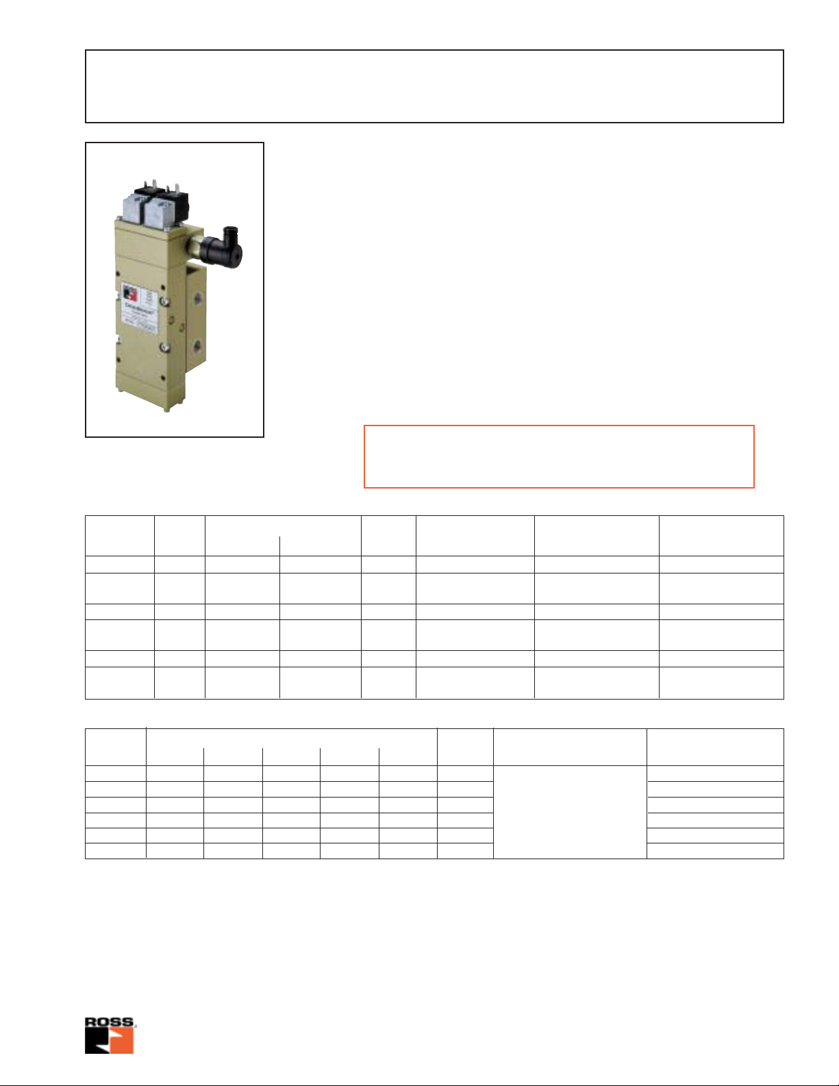
ROSS 5/2-way Double Valves with
CROSSMIRROR®-Sensing
For almost 40 years ROSS has been developing double
valves which have made a significant contribution to the
operating safety of pneumatically controlled presses. During this period our range of double valves has been developed continuously in response to the needs of press
manufacturers and users. Monitoring devices have also
been offered in a variety of designs to satisfy different requirements.
The range of double valves in 5/2-way configuration featuring the all-new CROSSMIRROR® -sensing system presented
in this leaflet incorporates all our experience and represents the state-of-the-art in ROSS double valves.
Selecting the double valve best suited to each application
requires considerable technical knowledge. If you need
further information or technical advice, please contact
ROSS or your nearest ROSS distributor or sales office.
CAUTION: On mechanical presses and other hazardous
machines with pneumatically operated clutches and brakes double valves at least should be used. Double valves
without self-monitoring should be used only if current regulations permit.
If the valves are used on presses in Germany, the
„Safety Regulations For Control Systems On Power-driven Presses for Metalworking zH 1/457“ must be observed.
For applications not covered by standard valves, please
consult ROSS. We reserve the right to make technical modifications in the course of further product development.
This all-new ROSS-Crossflow double valve with CROSSMIR-
®
-sensing is a 5/2-way valve with two individual soleno-
ROR
id pilot valves each actuating its own individual metalspool-sleeve valve element.
The spool-and-sleeve valve elements are arranged in parallel design and - as a safety-related feature - they are connected by „crossflow“ channels. In case of normal valve
operation both spools move synchronously; when de-actuated, the spools are in the upper position; and when actuated, they are in the lower position. Because of their redundant design and their self-monitoring capabilities, ROSS
5/2-way-Crossflow double valves with C
sing provide a very high safety standard for the control of
single- or double acting cylinders or rotary drives.
Additional safety features are incorporated in the base. In
the event of loss of air pressure at the inlet port a check
valve is installed to trap the downstream air, a small bleed
orifice slowly relieves the trapped air. Additionally a small
two-way valve provides safety in the case where inlet pressure is restored whilst the solenoids are still energized. To
guard against any sudden cylinder movement, this valve
provides a path to exhaust for one of the pilot valves which
puts the valve into an inoperable state until both solenoids
have been de-energized.
The new ROSS C
gned to exhaust the pilot supply to one solenoid pilot when
only one half of the valve is in an actuated position. This is
accomplished by connecting the pilot air supply system to
the main valve spool and sleeve. The connection is made
such that as the spool moves toward the actuated position
the pilot supply is vented to exhaust via the second valve
element. When the second valve element moves to the actuated position, it blocks the exhausting pilot air thereby
maintaining a constant supply. Pilot supply to the opposite
pilot is connected in a mirror image of the first pilot supply,
hence the name „cross mirror“.
ROSSMIRROR
®
-sensing system is desi-
ROSSMIRROR
®
-sen-
CONTENTS:
Product description........................................ Page 2
Specifications, model numbers ..................... Page 3
Dimensions ................................................... Page 4
Replacement parts ........................................Pages 5, 6
Flow characteristics, valve response times ...Page 7
General information....................................... Page 8
Cautions........................................................ Pages 9, 11
Operating instructions ................................... Page 10
2www.rosseuropa.com
Page 3
5/2-Way Double V alves
with CROSSMIRROR®-Sensing
SPECIFICATIONS
Design: Metal-to-metal spool-and-
sleeve valves, pressure-operated.
Air and spring returned.
Operation: Solenoid-operated airpiloted valves, 3/2-way-spring-return.
2)
Media
: compressed air,
dehydrated, filtered (5 µm),
lubricated or unlubricated.
Operating pressure: 2,5 to 10 bar.
Temperature range: 4° C to 50° C.
Mounting orientation: preferably
Pilot solenoid: according to VDE 0580.
Enclosure rating acc. to DIN 400 50 IP
65. Connector socket according to DIN
43650 Form A.
Solenoids rated for continuous duty.
Standard voltages:
24 V DC 110 V DC
24 V 50 Hz, 110 V 50 Hz, 230 V 50 Hz;
24 V 60 Hz, 110 V 60 Hz, 240 V 60 Hz.
Power consumption:
DC solenoids - 5,3 W
AC solenoids - 8,5 VA
vertically.
1)
Monitoring
: dynamically, cyclically,
internally.
The double valves listed have been approved by the following testing
and certificating authority:
BG-Fachausschüsse Eisen und Metall III und Hebezeuge II,
Deutschland: Certificate No. 99035
Double Valve
Nominal Size Operating pressure (bar) Weight Type Model Number3)Replacement valve
Diameter min. max. (kg) (with sub-base) (without sub-base)
10 G 3/8 2,5 10 3,8 CM 5/2 D7776A3410 7776A3400
10 G 3/8 2,5 10 3,9 CM 5/2 D7776A3411 7776A3401
with pressure switch
15 G 1/2 2,5 10 4,8 CM 5/2 D7776A4420 7776A4400
15 G 1/2 2,5 10 5,1 CM 5/2 D7776A4421 7776A4401
with pressure switch
15 G 3/4 2,5 10 4,8 CM 5/2 D7776A5410 7776A4400
15 G 3/4 2,5 10 5,1 CM 5/2 D7776A5411 7776A4401
with pressure switch
3)
Sub-base
Nominal Pipe size Weight Design Model Number
Diameter 1 2 3 4 5 (kg) Feature
10 G 1/2 G 3/8 G 3/8 G 3/8 G 3/8 1,1 D996C91
10 1/2 NPT 3/8 NPT 3/8 NPT 3/8 NPT 3/8 NPT 1, 1 996C91
15 G 3/4 G 1/2 G 1/2 G 1/2 G 1/2 1,6 D1049C91
15 3/4 NPT 1/2 NPT 1/2 NPT 1/2 NPT 1/2 NPT 1,6 1049C91
15 G 3/4 G 3/4 G 3/4 G 3/4 G 3/4 1,6 D1153C91
15 3/4 NPT 3/4 NPT 3/4 NPT 3/4 NPT 3/4 NPT 1,6 1153C91
Notes
1) In addition, a pressure-switch-monitored model of this valve is available. In case of a malfunction or pressure failure, the pressure
switch can be used for signaling abnormal operation. Important Note: The pressure switch is not designed to be integrated in a safety
circuitry as its response may be delayed, depending on the type of malfunction.
2) It is recommended to use compressed air, filtered and unlubricated. If lubricated air must be used, we recommend oils conforming to
ISO viscosity classes 32-46 (DIN 51519).
3) When ordering the valve, specify AC or DC voltage and frequency for operating the pilot solenoids (see Specifications above).
Sub-base is equipped
with check valve in
pipe connection 1 and
2/2-way valve as reset
after pressure energy
failure
3www.rosseuropa.com
Page 4
5/2-Way Double V alves
with CROSSMIRROR®-Sensing
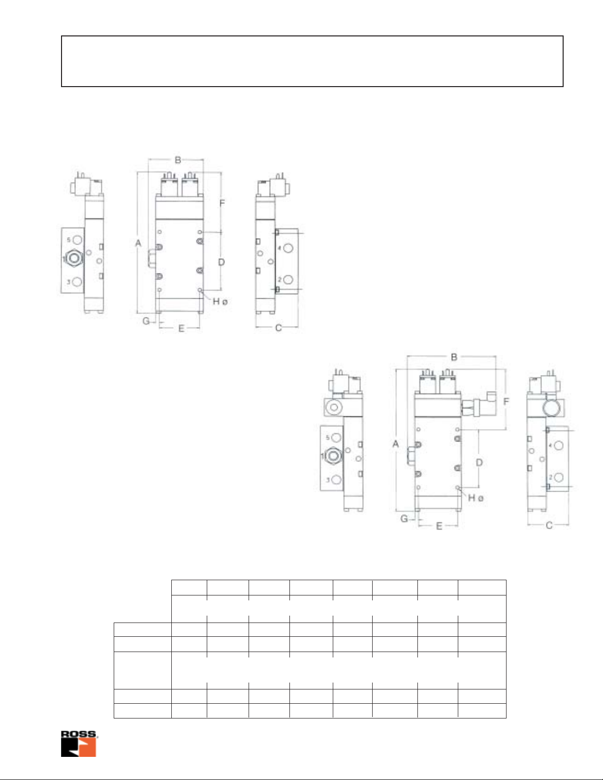
Dimensions –
Valve with ported sub-base
Dimensions –
Valve with ported sub-base and
pressure switch
Dimensional drawings:
Mounting interface sub-base to machine
dimensions: D; E; F; G and H
Dimensions in mm
ND 10 282 104 81 115,6 75 119,5 7 7 or M 6
ND 15 310 108 106 136 81 122 7 7 or M 6
ND 10 282 172 81 115,6 75 119,5 7 7 or M 6
ND 15 310 175 106 136 81 122 7 7 or M 6
ABCDEFGH ø
Double valve with ported sub-base
Double valve with ported sub-base
and pressure switch
4www.rosseuropa.com
Page 5
5/2-Way Double V alves
with CROSSMIRROR®-Sensing
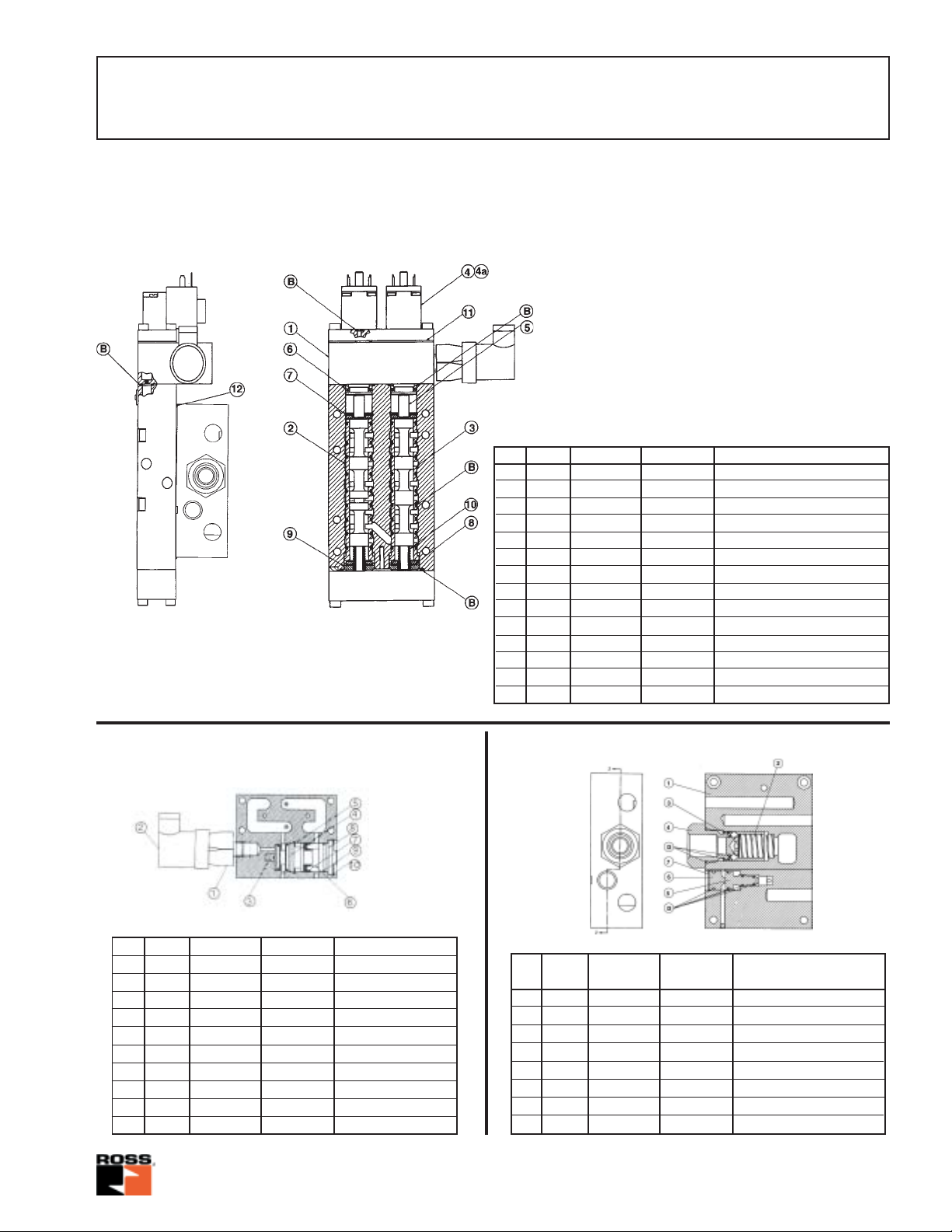
Replacement parts –
Valve with pressure switch
Valve Numbers
7776A3401
7776A4401
Pos. Qty. 7776A3401 7776A4401 Description
1 1 854C89 883C89 Sensing as semb ly
2 1 420H90 418A90 Inlet spool/sleeve
3 1 421H90 419A90 Outlet spool/sleeve
4 2 1044H79 1044H79 Pilot assembly
4a 2 – – Coil
5 2 577A09 603A09 Actuation piston
6 2 583A32 503A32 Seal
7 2 139J22 143J22 Retaining ring
8 4 288A32 289A32 Bumper
9 2 1460A25 1585A25 Spacer
10 2 478A13 497A13 Compression spring
11 1 860A11 886A11 Gasket (pilot-to-body)
12 1 861A11 885A11 Gasket (body-to-sub-base)
B 1 1575K77 1577K77 Seal kit
Pressure switch assembly Sub-base assembly
Pos. Qty. 854C89 883C89 Description
1 1 518E30 518E30 Pressure switch
2 1 522E30 522E30 Connector socket
3 1 207A13 207A13 Spring
4 1 200A97 200A97 Insert assy.
5 1 144J22 144J22 Retaining ring
6 1 580A09 580A09 Piston
7 1 768J32 768J32 U-cup seal
8 1 678B25 678B25 Stem guide
9 1 207J15 207J15 O-Ring
10 1 131J22 131J22 Retaining ring
Pos. D996C91Qty. Description
1 1 D1048B91 D1130B91 Valve body assembly
2 1 488A13 222A13 Spring
3 1 185A88 351A88 Valve poppet assembly
4 1 D332B85 D334B85 Check valve assembly
5 1 147A90 147A90 Spool assembly
6 1 157A85 157A85 Plug assembly
7 1 133J22 133J22 Retaining ring
D 1 1576K77 1578K77 Seal kit
D1049C91
D1153C91
5www.rosseuropa.com
Page 6

Replacement parts –
Valve without pressure switch
Valve Numbers
7776A3400
7776A4400
5/2-Way Double V alves
with CROSSMIRROR®-Sensing
Sub-base assembly
Pos. Qty. 7776A3400 7776A4400 Description
1 1 853C89 884B89 Sensing assembly
2 1 420H90 418A90 Inlet spool/sleeve
3 1 421H90 419A90 Outlet spool/sleeve
4 2 1044H79 1044H79 Pilot valve assembly
4a 2 – – Coil
5 2 577A09 603A09 Actuating piston
6 2 583A32 503A32 Seal
7 2 139J22 143J22 Retaining ring
8 4 288A32 289A32 Bumper
9 2 1460A25 1585A25 Spacer
10 2 478A13 497A13 Compression spring
11 1 860A11 886A11 Gasket (pilot-to-body)
12 1 861A11 885A11 Gasket (body-to-sub-base)
B 1 1575K77 1577K77 Seal kit
Pos. D996C91Qty. Description
1 1 D1048B91 D1130B91 Valve body assembly
2 1 488A13 222A13 Spring
3 1 185A88 351A88 Valve poppet assembly
4 1 D332B85 D334B85 Check valve assembly
5 1 147A90 147A90 Spool assembly
6 1 157A85 157A85 Plug assembly
7 1 133J22 133J22 Retaining ring
D 1 1576K77 1578K77 Seal kit
D1049C91
D1153C91
6www.rosseuropa.com
Page 7

5/2-Way Double V alves
with CROSSMIRROR®-Sensing
Flow characteristics (kv-values)
kv - values
Valve No.: 7776A3400 & 7776A3401
with sub-base D996C91
Inlet G 1/2; Outlet G 3/8
Flow direction Function Function
Normal Abnormal Normal Abnormal
Side „A“ Side „B“ Side „A“ Side „B“
1 to 2 1,8 1,4 1,8 2,78 2,0 2,78
1 to 4 1,5 – – 2,95 – –
2 to 3 1,4 – – 2,34 – –
4 to 5 2,4 1,8 1,8 6,26 3,65 3,13
Valve No.: 7776A4400 & 7776A4401
with sub-base D1049C91
Inlet G 3/4; Outlets G 1/2 - G 3/4
V alve response times
Valve No.: 7776A3400 and 7776A3401 5/2 Nominal diameter 10
7776A4400 and 7776A4401 5/2 Nominal diameter 15
Solenoid operated: 230V / 50Hz
T est pressure: 3; 6 bar
Work ports 2 and 4 are closed without volume.
Response times in ms
Flow direction Pressure 7776A.... 7776A....
3400 3401 3400 3401 4400 4401 4400 4401
3 bar 6 bar 3 bar 6 bar
ENERGIZED 1 to 4 rising 34 40 25 28 47 41 34 35
Normal function 2 to 3 falling 30 34 26 27 45 38 35 31
DE-ENERGIZED 1 to 2 rising 29 44 44 39 61 62 60 60
Normal function 4 to 5 falling 38 39 40 37 59 57 62 62
ENERGIZED
Abnormal function 1 to 2 rising 50 47 53 46 54 59 70 63
Side A
2)
4 to 5 falling 45 50 52 49 50 56 56 57
ENERGIZED
Abnormal function 1 to 2 rising 41 47 46 57 64 56 52 52
3)
Side B
4 to 5 falling 28 54 47 53 61 57 55 67
1)
1) Response time: ENERGIZED - average time required to fill volume to 90% of supply pressure.
DE-ENERGIZED - average time required to exhaust volume to 10% of supply pressure.
2) 3) In case of malfunctions due to differing actuation functions of pilot valves or/and the main v alv e systems of v alv e side A or B.
7www.rosseuropa.com
Page 8

5/2-Way Double V alves
with CROSSMIRROR®-Sensing
GENERAL INFORMA TION
The new ROSS 5/2-way
CROSS MIRROR
®
double
valve is designed as a self-monitoring valve. It can
be used for controlling pneumatic presses for coldforming of metal (optionally in connection with additional devices such as pilot-operated check valves),
if the electric control of the valve is designed in
accordance with prEN..."Pneumatic Presses" (June
1998). The mirror-image-type air flow pattern in the
CROSS MIRROR® double valve allows an alternating
pressure buildup from the de-actuated (pressure
port 1 to work port 2) to the actuated mode (pressure
port 1 to work port 4) only if the following conditions
are fulfilled:
1. The solenoid control signals must actuate the
solenoid pilot valves synchronously or with a time
difference of < 0,5 sec.
2. Both main valve systems must be in the at-rest
position before the valve is actuated.
3. Both main valve systems must have moved into
the actuated position within a defined time span of
< 0,5 sec.
Pressure Switch Unit (optional)
In case of a valve malfunction, the standard valve
shifts back to the at-rest-position; i.e. pressure
from port 1 to port 2. By actuating the valve again,
the cause of the malfunction (dirt or asynchronous
signals) can be eliminated and the valve can
operate normally again. In order to detect such a
malfunction, a valve with pressure switch unit is
available.
This pressure switch unit can be used to signal a
malfunction and to interrupt valve piloting. Properly
wired into the electric circuit, the pressure switch
can prevent a new valve cycle until the malfunction
has been analyzed and eliminated.
Pressure switch unit
Q
O
AB
12
(optional)
N
P5
12
Additional work-safety features are incorporated in
the base:
1 . A check valve in the inlet port prevents the cylinder from falling abruptly when a loss of pressure
occurs. In such a case a small bypass will allow the
cylinder to move gradually into the at-rest-position.
2
. When an unexpected loss of pressure occurs with
the electric pilot signal still being present, another
valve integrated in the sub-base is designed to
prevent any uncontrolled valve shifting and cylinder
movement that might occur when the pressure
returns. In case of a pressure loss this valve opens
the pilot air line and thereby prevents the main valve
system from shifting when pressure returns. All pilot
valves and main valve systems must be in the atrest-position before a restart of the system after a
pressure loss.
OUTLET 4
3
1
2
CHAMBER "A" CHAMBER "B"
2A
EXH. 5
OUTLET 2
A5
A2
A4
A8
A3
A7
A1
A6
1A
AIR SUPPLY
3
1
2
2B
B2
B8
B7
B6
1B
Pressure Port 1
EXH. 3
B4
B3
B1
B5
Sub-base with
pressure failure
monitoring
Schematic
(V alve in the de-actuated position)
8www.rosseuropa.com
Page 9
5/2-Way Double V alves
with CROSSMIRROR®-Sensing
CAUTIONS
Installation
Double valves should be installed only by persons
trained and experienced in the installation of such
equipment.
Lines
Air supply directed through air preparation units and
pressure regulator to pressure por
t 1 requires
minimum line capacity of pressure port 1.
Lines and line connections must be in accordance
with relevant safety regulations, e.g. prEN...
Pneumatic Presses“ (June 1998).
Cylinder speed regulation
When installing components between the double
valve and the work element, the relevant safety
regulations e.g. prEN... Pneumatic Presses“ (June
1998) need to be observed.
Air preparation
An efficient filter unit (at least 5 µm) must be mounted
before the valve. Use of a lubricator is not necessary
if the work element is designed for non-lube
operation.
Silencers
Silencers can be mounted to ports 3 and 5 of the
doub
le valve . These must be in accordance with the
relevant safety regulations, as for instance prEN...
Pneumatic Presses“ (June 1998). Restricting the
exhaust port of a double valve can adversely affect
its proper operation. Silencers must be resistant to
clogging and have a flow capacity larger than the
exhaust capacity of the valve.
Piloting
Electrical piloting of the double valve must be in
accordance with the relevant (application-specific)
safety regulations.
SAFETY-RELEV ANT CAUTIONS:
• The use of surge suppressors in the solenoid
circuits may slow down the de-energisation of the
solenoid coils and thereby may delay response of
the valve elements which may increase exhaust time.
Depending on the application, the electrical
•
connection with the valve may have to be secured
separately.
• In case of machine vibration > 25g a suitable
shock absorbing mounting device has to be provided
for the valve.
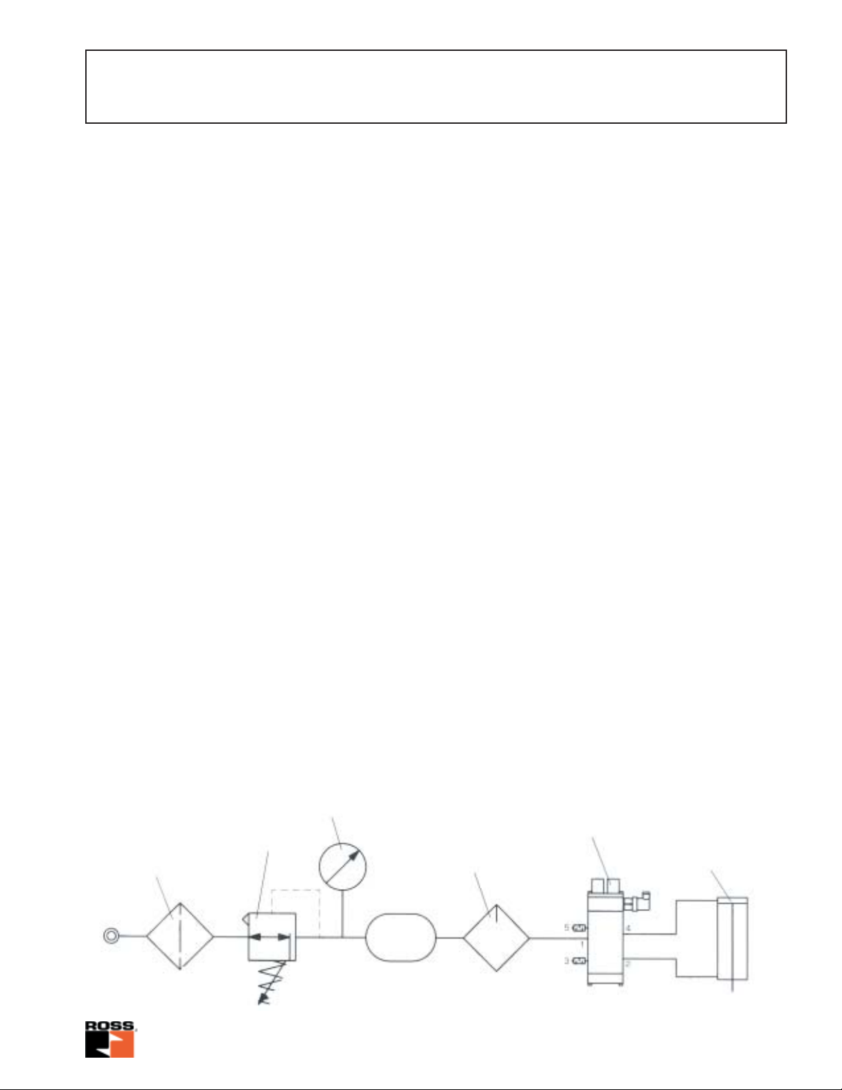
Mounting schematic (example)
Pressure reducing
Filter and
water separator
valve
Pressure gauge
Volume
Lubricator
5/2-CROSSMIRROR
double valve
Pressure switch
®
Double-acting
cylinder
9www.rosseuropa.com
Page 10

5/2-Way Double V alves
with CROSSMIRROR®-Sensing
OPERATING INSTRUCTIONS
Start-up
Prior to start-up, the installation must be checked thoroughly by persons trained and experienced in the
operation of pneumatic equipment. Make sure that the maximum operating pressure specified on the valve
label will not be e
rest-position. For further testing, a functional test as well as a pressure failure test must be performed.
Functional test
T
est Result
1. Actuate solenoid A Piston does not move
2. Actuate solenoid B Piston does not move
3. Actuate solenoid A, then actuate
solenoid B after t > 0,5s Piston does not move
4. Actuate solenoid B, then actuate
solenoid A after t > 0,5s Piston does not move
5. Actuate solenoids A and B after t < 0,5s
then de-energize solenoid A and Piston moves, but returns to at-rest-position after solenoid A
re-actuate after t > 0,5s is de-energized, and remains in that position
6. As under 5., however, test to be
performed with solenoid B See result 5
xceeded. When operating pressure is applied, the cylinder piston must move into the at-
Pressure failure test
The valve is in the at-rest position. T urn off operating
pressure at port 1 and exhaust the operating
pressure line. Actuate the valve in the normal way
(solenoids A and B in t < 0,5s), and keep the
solenoids energized. Then apply operating pressure
to port 1 again. The piston is not supposed to lea ve
its position. For checking the check v alv e in port 1,
close and exhaust the operating pressure line. If
the check valves close properly, the piston will not
move downward quic kly . Depending on the intensity
of usage, the check valves should be checked at
three month’ intervals.
Malfunctions
In case of malfunctions, we recommend to check/
e
xchange the double valve immediately.
Maintenance, testing
Maintenance and testing procedures must follow
the rules and guidelines set by the respective nati-
onal w
should only be performed by persons trained and
experienced in the use of pneumatic equipment. It
is recommended that maintenance and test
procedures be performed at least once a year,
unless otherwise specified.
Repair
It is recommended that double valves which need
to be serviced be handed over to a ROSS service
point. Customers maintaining their own repair
service have to make sure that only original spare
par
Pneumatic equipment should be repaired only by
persons trained and experienced in the repairing of
such equipment, guided by these operating
instructions. Information about valve repair and/or
the exchange of a valve must be written down in
the machine operation documentation.
ork-safety institutions. These procedures
ts (as specified in the ROSS parts lists) be used.
10www.rosseuropa.com
Page 11

with CROSSMIRROR®-Sensing
A
B
Male thread
5/2-Way Double Valves
MUFFL-AIR® -Silencers
Pipe ø k
size value number A B
R 3/8 5,0 D5500A3003 32 96
R 1/2 6,1 D5500A4003 32 96
R 3/4 6,1 D5500A5013 32 96
Cautions
- Model Dimensions - mm
v
PRE-INSTALLATION or SERVICE
1. Before servicing a valve or other pneumatic component, be sure
that the electrical supply is turned off and that the entire pneumatic
system is shut off and exhausted.
2. All ROSS products, including service kits and parts, should be
installed and/or serviced only by persons having training and
experience with pneumatic equipment. Because any installation can
be tampered with or need servicing after installation, persons
responsible for the safety of others or the care of equipment must
check every installation on a regular basis and perform all
necessary maintenance.
3. All applicable instructions should be read and complied with before using any fluid power system in order to prevent harm to persons and/or equipment. In addition, overhauled or serviced valves
must be functionally tested prior to installation and use.
4. Each ROSS product should be used within its specification limits.
In addition, use only ROSS parts to repair ROSS products. Failure
to follow these directions can adversely affect the performance of
the product or result in the potential for human injury.
FILTRATION and LUBRICATION
5. Dirt, scale, moisture, etc. are present in virtually every air sys-
tem. Although some valves are more tolerant of these contaminants
than others, best performance will be realized if a filter is installed to
clean the air supply, thus preventing contaminants from interfering
with the proper performance of the equipment. ROSS recommends
a filter with a 5-micron rating for normal applications.
6. All standard ROSS filters and lubricators with polycarbonate
plastic bowls are designed for compressed air applications only. Do
not fail to use the metal bowl guard, where provided, to minimize
danger from high pressure fragmentation in the event of bowl failure. Do not expose these products to certain fluids, such as alcohol
or liquified petroleum gas, as they can cause bowls to rupture,
creating a combustible condition, hazardous leakage, and the
potential for human injury. Immediately replace a crazed, cracked
or deteriorated bowl. When the bowl gets dirty, replace it or wipe it
with clean dry cloth.
7. Only use lubricants which are compatible with materials used in
the valves and other components in the system. Normally,
compatible lubricants are petroleum base oils with oxidation
inhibitors, an aniline point between 82°C and 104°C, and an ISO 32,
or lighter, viscosity. Avoid oils with phosphate type additives which
can harm polyurethane components, potentially leading to valve
failure and/or human injury.
AVOID INTAKE / EXHAUST RESTRICTION
8. Do not restrict the air flow in the supply line. To do so could re-
duce the pressure of the supply air below the minimum requirements for the valve and thereby cause erratic action.
9. Do not restrict a poppet valve's exhaust port as this can adversely affect its operation. Exhaust silencers must be resistant to clogging and have flow capacities at least as great as the exhaust capacities of the valves. Contamination of the silencer can result in
reduced flow and increased back pressure. ROSS expressly dis-
claims all warranties and responsibility for any unsatisfactory performance or injuries caused by the use of the wrong type, wrong
size, or inadequately maintained silencer installed with a ROSS
product.
DOUBLE VALVES
10. Mechanical power presses and other potentially hazardous ma-
chinery using a pneumatically controlled clutch and brake mechanism must use a press control double valve with a monitoring device. A double valve without a self-contained monitoring device
should be used only in conjunction with a control system which assures monitoring of the valve. All double valve installations involving
hazardous applications should incorporate a monitoring system
which inhibits further operation of the valve and machine in the
event of a failure within the valve mechanism.
11www.rosseuropa.com
Page 12

ROSS
Robert-Bosch-Strasse 2
D-63225 Langen / Germany
Phone: +49-6103-7597-0
Fax: +49-6103-74694
www.rosseuropa.com
EUROPA GmbH
ROSSROSS
ROSS
ROSSROSS
P.O. Box 7015,
Troy, Michigan 48007 U.S.A.
Phone: +1-248-764-1800
Fax: +1-248-764-1850
www.rosscontrols.com
CONTROLS
®
ROSS SOUTH AMERICA Ltda.
Rua Olavo Goncalves, 43/47 - Centro
Sao Bernardo do Campo - Sao Paulo
Brazil - CEP 09725-020
Phone: +55-11-4335-2200
Fax: +55-11-4335-3888
ROSS
Cakemore Road, Rowley Regis,
Warley, West Midlands, B65 OQW
United Kingdom
Phone: +44-121 559 4900
Fax: +44-121 559 5309
www.rossuk.com
UK Ltd.
ROSS
10209-5 Tana, Sagamihara-shi
Kanagawa-pref. 229-11, Japan
Phone: +81-427-78-7251
Fax: +81-427-78-7256
www.rossasia.co.jp
ASIA K.K.
ROSS ASIA K.K.-
CHINA LIAISON OFFICE
ROSS CONTROLS INDIA Pvt. Ltd.
Plot 113, Industrial Estate
Ambattur
Chennai 600 058, India
Phone: +91-44-8413136
Fax: +91-44-8413137
www.rossindia.com
Room 701, Taiji Building,
No. 33.1249 Street
Xikang Road
Shanghai, China
Phone: +86-21-6296-5123
Fax: +86-21-6299-0529
W ARRANTY
Products manufactured by ROSS are warranted to be free of defects in material and workmanship for a period of one year
from the date of purchase. ROSS' obligation under this warranty is limited to repair or replacement of the product or refund
of the purchase price paid solely at the discretion of ROSS and provided such product is returned to ROSS freight prepaid
and upon examination by ROSS is found to be defective. This warranty shall be void in the event that product has been
subject to misuse, misapplication, improper maintenance, modification or tampering. The warranty expressed above is in
lieu of and exclusive of all other warranties and ROSS expressly disclaims all other warranties either expressed or implied with respect to merchantability or fitness for a particular purpose. ROSS makes no warranty with respect to its products meeting the provisions of any governmental occupational safety and/or health laws or regulations. In no event shall
ROSS be liable to purchaser, user, their employees or others for incidental or consequential damages which may result
from a breach of the warranty described above or the use or misuse of the products. No statement of any representative
or employee of ROSS shall extend the liability of ROSS as set forth herein.
Printed in Germany 11-2003 Form No. RE-E-A 10200
12www.rosseuropa.com
Page 13

PRODUCT DATA SHEET INFORMATION
environment
safety
e
technology
productivity
5/2 CROSSMIRROR® Series 77
Solenoid Pilot Controlled Pneumatic Double Valve
Control Reliable Energy Isolation
• Self-contained dynamic monitoring system requires no additional valve
monitoring controls
• Base mounted, stainless steel spool valve construction
• Status indication switch (ready-to-run) to inform machine controller of valve
condition; MUST be integrated into machine controls in order to prevent run
signal until fault is cleared in valve
• Applications include small size pneumatic cylinder-operated presses, valve
operators, and safety latches
ISO 13849-1:2006 Category 4
PL e applications
• Base mounted, stainless steel spool valve construction
• Sistema library data available (consult ROSS or visit the Safety industry page at
www.rosscontrols.com)
• Explosion proof solenoid pilot available, for more information consult ROSS
Cylinder Return to
Ordering Information
Valve Size 2
Model* Port Sizes CV Pressure Dimensions inches (mm) Weight Replacements*
Number 1 2, 3 , 4 , 5 1-2 1-4 2-3 4-5 Switch A B C lb (kg) Valve No. Base No.
7776A3410 1/2 3/8 2.0 1.6 1.6 2.8 Without 11.1 (282) 4.1 (104) 3.2 (81) 7.6 (3.4) 7776A3400 996C91
7776A3411 1/2 3/8 2.0 1.6 1.6 2.8 With• 11.1 (282) 6.7 (170) 3.2 (81) 8.4 (3.8) 7776A3401 996C91
* Model number includes base supplied with NPT threads. For BSPP threads, order model or base with a “D” prefix, e.g., D7776A3410, D996C91.
• For pressure switch option, order model or v alve with a “Z” suffix for 110 volts AC or “W” suffix for 24 volts DC , e.g., 7786A3411Z, 7776A3401Z.
Valve Size 4
7776A4420 3/4 1/2 3.2 3.4 2.7 7.2 Without 12.1 (307) 4.3 (109) 4.1 (104) 10.2 (4.6) 7776A4400 1049C91
7776A4421 3/4 1/2 3.2 3.4 2.7 7.2 With• 12.1 (307) 6.9 (175) 4.1 (104) 11.2 (5.1) 7776A4401 1049C91
7776A5410 3/4 3/4 3.2 3.4 2.7 7.2 Without 12.1 (307) 4.3 (109) 4.1 (104) 10.2 (4.6) 7776A4400 1153C91
7776A5411 3/4 3/4 3.2 3.4 2.7 7.2 With• 12.1 (307) 6.9 (175) 4.1 (104) 11.2 (5.1) 7776A4401 1153C91
* Model number includes base supplied with NPT threads. For G threads, order model or base with a “D” prefix, e.g., D7776A4420, D1049C91.
• For pressure switch option, order model or valve with a “Z” suffix for 110 volts AC or “W” suffix for 24 volts DC, e.g., 7776A4421W, 7776A4401W.
Valve Size 4 SAE
S7776A4H10 SAE 12 SAE 12 3.2 3.4 2.7 7.2 Without 12.1 (307) 4.3 (109) 4.1 (104) 10.2 (4.6) 7776A4400 1159G91
S7776A4H11 SAE 12 SAE 12 3.2 3.4 2.7 7.2 With• 12.1 (307) 6.9 (175) 4.1 (104) 11.2 (5.1) 7776A4401 1159G91
* Model number includes base. • For pressure switch option, order model or valve with a “Z” suffix for 110 volts AC or “W” suffix for 24 volts DC, e.g.,
S7776A4H11Z, 7776A4401Z.
B
Standard Specifications
Pilot
Pilot Solenoids: Rated for continuous duty.
A
Standard Voltages: 100-110 volts, 50 Hz; 100-120 volts, 60 Hz;
24 volts DC; 110 volts DC. For other voltages, consult ROSS.
Power Consumption: Each solenoid, 18 VA inrush, 14 VA
holding on 50 or 60 Hz; 6 watts on DC.
Electrical Connections: Uses cord-grip connectors at solenoids.
Order connectors separately, see accessories.
Ambient Temperature: 40° to 120°F (4° to 50°C).
Flow Media: Filtered air; 5 micron recommended.
Inlet Pressure: 40 to 150 psig (2.5 to 10 bar).
Media Temperature: 40° to 175°F (4° to 80°C).
This valve is not designed for use in power press clutch/brake applications.
C
Base
Valve
Chambers
1
Air Supply
5
2
Home Position
Pressure
Switch
Pilot
Valve
Base
4
3
Designing toward
Zero-Harm.
Designing to
maximize return
on investment.
Designing to save
energy and reduce
greenhouse gases.
Designing to optimiz
reduction processes
and applications.
Page 14

PRODUCT DATA SHEET INFORMATION
5/2 CROSSMIRROR® Series 77
Two-Hand Pressure Controlled Pneumatic Double Valve
Control Reliable Energy Isolation
This Series 77 5/2 CrossMirror® valve is a control reliable, two hand pressure controlled 4-way
double valve that is controlled by two separate pneumatic signals essentially providing “AND”
gate control for the output ports. Both pilot signals must be provided within approximately 500
milliseconds of each other to actuate the valve.
Proper actuation shifts output pressure to port 4. If the valve is not actuated, not provided
appropriate pneumatic signals within the discordance window or if the valve actuates abnormally,
inlet pressure will only be passed to port 2 - cylinder retracted.
This valve is constructed with precision, stainless steel spools as the main valve elements, and
is designed to offer added safety to the operation of many pneumatically controlled machines.
• Requires two inputs within 500 ms
• Self-contained dynamic monitoring system requires no additional valve monitoring controls
• Senses asynchronous inputs via status indicator switch
• Status indication switch available to be integrated with electrical safety control system where
available
• Applications include small size pneumatic cylinder-operated presses, valve operators,
and safety latches
• Base mounted, stainless steel spool valve construction
• Sistema library data available (consult ROSS or visit the Safety industry page at
www.rosscontrols.com)
ISO 13849-1:2006 Category 4
PL e applications
APPLICATIONS: Pneumatic cylinder applications.
• Tw o hand control EN574 Type III C
• Pinch point applications
• Shearing equipment
• Forming applications
• Cutting applications
• Clamping applications
Cylinder Return to
Home Position
VALVE OPERATION
Normal Operation:
After installation the valve is operated by pressurizing both pilot supply ports (S1 and S2) simultaneously. This causes both main
valve elements to be actuated so that air from inlet port 1 flows to outlet port 4. Air downstream of port 2 is exhausted through port 3.
When the pilot supply ports are de-pressurized, both valve elements are de-actuated, and air then flows from inlet port 1 to outlet
port 2. Air downstream of port 4 is exhausted through port 5.
Safety Function:
If the two main valve elements are not actuated or de-actuated synchronously, within 500ms , the v alve def aults so that outlet port
2 receives full inlet pressure, and outlet port 4 is exhausted through port 5. If this abnormal operation is the result of a temporary
circumstance, the valve will be ready to resume normal operation as soon as both pilot signal ports have been de-pressurized and
both main valve elements hav e returned to their normal ready-to-run position. Applying pressure to both signal ports simultaneously
will resume normal operation.
If the cause of the abnormal operation is still present, the valve will either remain in the default position (pressure on port 2 and
not port 4) or will again go into this position on the next actuation attempt. The source of the abnormality must be investigated
and corrected before further operation.
Pressure Switch:
Valv es with model numbers ending in the n umber 1 hav e a pressure s witch to provide user f eedback when mo vement of the main
valve elements was asynchronous.
This valve is not designed for use in power press clutch/brake applications.
www.rosscontrols.com
Page 15

Ordering Information
A
Valve Size 2
Model* Port Sizes CV Pressure Dimensions inches (mm) Weight Replacements*
Number 1 2, 3, 4, 5 1-2 1-4 2-3 4-5 Switch A B C lb (kg) Valve No. Base No.
7786A3410 1/2 3/8 2.0 1.6 1.6 2.8 Without 10.9 (277) 4.1 (104) 3.2 (81) 7.6 (3.4) 7786A3400 996C91
7786A3411 1/2 3/8 2.0 1.6 1.6 2.8 With• 10.9 (277) 6.7 (170) 3.2 (81) 8.4 (3.8) 7786A3401 996C91
* Model number includes base supplied with NPT threads. For G threads, order model or base with a “D” prefix, e.g., D7786A3410, D996C91
• For pressure switch option, order model or v alve with a “Z” suffix for 110 volts AC or “W” suffix for 24 volts DC , e.g., 7786A3411Z, 7786A3401Z .
Valve Size 4
7786A4420 3/4 1/2 3.2 3.4 2.7 7.2 Without 12.1 (307) 4.3 (109) 4.1 (104) 10.6 (4.6) 7786A4400 1049C91
7786A4421 3/4 1/2 3.2 3.4 2.7 7.2 With• 12.1 (307) 6.9 (175) 4.1 (104) 11.6 (5.1) 7786A4401 1049C91
7786A5410 3/4 3/4 3.2 3.4 2.7 7.2 Without 12.1 (307) 4.3 (109) 4.1 (104) 10.6 (4.6) 7786A4400 1153C91
7786A5411 3/4 3/4 3.2 3.4 2.7 7.2 With• 12.1 (307) 6.9 (175) 4.1 (104) 11.6 (5.1) 7786A4401 1153C91
* Model number includes base supplied with NPT threads. For G threads, order model or base with a “D” prefix, e.g., D7786A4420, D1049C91.
• For pressure switch option, order model or valve with a “Z” suffix for 110 volts AC or “W” suffix for 24 volts DC, e.g., 7786A4421W, 7786A4401W.
Valve Size 4 SAE
S7786A4H10 SAE 12 SAE 12 3.2 3.4 2.7 7.2 Without 12.1 (307) 4.3 (109) 4.1 (104) 10.6 (4.6) 7786A4400 1159G91
S7786A4H11 SAE 12 SAE 12 3.2 3.4 2.7 7.2 With• 12.1 (307) 6.9 (175) 4.1 (104) 11.6 (5.1) 7786A4401 1159G91
* Model number includes base.
• For pressure switch option, order model or valve with a “Z” suffix for 110 volts AC or “W” suffix for 24 volts DC, e.g.,S7786A4H11Z, 7786A4401Z.
B
C
Standard Specifications
Ambient Temperature:
Typical 2-Hand-Anti-Tie-Down Application
Customer
Supplied
3/2 Valve
Customer
Supplied
3/2 Valve
40° to 120°F (4° to 50°C).
Media Temperature:
40° to 175°F (4° to 80°C).
Flow Media:
Filtered air; 5 micron recommended.
Inlet Pressure:
40 to 100 psig (2.5 to 7 bar).
Pilot Pressure:
Must be equal or greater than inlet pressure, but should not
exceed maximum inlet pressure.
CROSSMIRROR
Control Reliable
Pneumatic 5/2 “AND” Gate
®
S1 S2
5
1
3
Customer
Supplied
4
2
Cylinder
Pressure Switch Rating:
Max Current 4A, Max 250 volts AC .
Max Current 50 mA, Max 24 volts DC.
Pressure Switch: Pressure Switch signal indicates when
the input signals or parts movement is asynchronous.
Status Indicator (pressure switch)
Terminals 1 and 4 are connected when air pressure is
present and the valve is “Ready-to-Run”. If an abnormal
operation has occured or pressure is removed from the
valve inlet, terminals 1 and 2 are connected.
Note: DC voltage pressure switches do not have a
ground terminal.
Pin 1: Common
Pin 2: Normally Closed
Pin G: Not used
Pin 4 : Normally Open
www.rosscontrols.com
Page 16

ACCESSORIES
ELECTRICAL CONNECTORS
Electrical connectors are required to connect the valve solenoids to the drop cords supplying electrical
power.
Each connector can be positioned so that the cord exits upward or to the side. Cords of 6 mm to 10 mm
diameter can be used. Connectors with a light in a translucent housing are also available to serve as
indicator lights. Order connectors by the part numbers given in the chart below.
WIRED CONNECTORS have a 2 meter (6½ ft) cord with three 18 gauge conductors. Cord exits upw ard,
and is available in either 6 mm or 10 mm diameter.
CONNECTORS for THREADED CONDUIT accept 1/2 inch electrical conduit fittings.
Model Numbers of Electrical Connectors
Connector Type Without Light With Light*
For use with dropcord
(Cord not included)
Wired with 6-mm cord 721K77 720K77*
Wired with 10-mm cord 371K77 383K77*
937K87 936K87*
CAUTION:
Do not use electrical connectors with surge suppressors, as
this may increase valve response time when de-actuating
the solenoids.
For use with threaded conduit 723K77 724K77*
Service Kits for Two-Hand Pressure Controlled Valves
Valve Valve Body Valve Body Base Pressure Switch Pressure Pressure
Valve Model Seal and Gasket Service Kit Service Kit Assembly Service Switch Switch Connector
Size Number Kit Model Number Model Number Model Number Kit Model Number Model Number Model Number
7786A3400 2216K77 2218K77 1694K77 N/A N/A N/A
2
7786A3401 2216K77 2218K77 1694K77 1696K77 AC - 518E30 522E30
DC - 798E30
7786A4400 2217K77 2219K77 1695K77 N/A N/A N/A
4
7786A4401 2217K77 2219K77 1695K77 1696K77 AC - 518E30 522E30
DC - 798E30
COMPANY INFORMATION
Your local ROSS distributor is:
In 1954 ROSS patented the first double valve for
the most demanding of safety applications: metal
forming press clutch and brake control. Since that
time, ROSS has patented several improved versions
of the double valve and expanded its safety product
offering. ROSS has become recognized as the
premier supplier of high-quality pneumatic and
hydraulic safety components for various applications
in metal forming and other industries.
ROSS CONTROLS
Customer Svs. 1-800-GET-ROSS
Technical Svs. 1-888-TEK-ROSS
ROSS EUROPA GmbH
Germany
Fax: 49-6103-74694
info@rosseuropa.com
Printed in the U.S.A. – Rev. 12/12 © 2012 ROSS CONTROLS®. All Rights Reserved. Form NPS005
ROSS ASIA
Fax: 81-427-78-7256
custsvc@rossasia.co.jp
U.S.A.
www.rosscontrols.com
®
K.K.
Japan
®
ROSS UK Ltd.
United Kingdom
Fax: 44-121-559-5309
sales@rossuk.co.uk
ROSS CONTROLS
India
Fax: 91-44-2625-8730
rossindia@airtelmail.in
WARRANTY and CAUTIONS
Standard ROSS warranty and cautions apply, available upon
request or at www.rosscontrols.com
®
INDIA Pvt. Ltd.
ROSS SOUTH AMERICA Ltda.
Brazil
Fax: 55-11-4335-3888
vendas@ross-sulamerica.com.br
DIMAFLUID s.a.s.
France
Fax: 33-01-4945-6530
dimafluid@dimafluid.com
ROSS CONTROLS
(CHINA) Ltd.
China
Fax: 86-21-6915-7960
alvinzhurong@vip.163.com
 Loading...