

Page 1
DM
1
Series E
New Product
Introduction
Simplified
Schematic
Port Size C
Model Number* In-Out Exh. In-Out Out-Exh. lb (Kg)
DM1ENA20**31 1/4 1/2 1.34 2.43 5.0 (2.27)
DM1ENA21**31 3/8 1/2 1.92 2.43 5.0 (2.27)
* NPT port threads. For BSPP threads , replace “N” in the model
number with a “D”.
** Insert voltage code: “A” = 24 volts DC, “B” = 110 volts AC,
“C” = 220 volts AC, “D” = 12 volts DC.
V
Weight
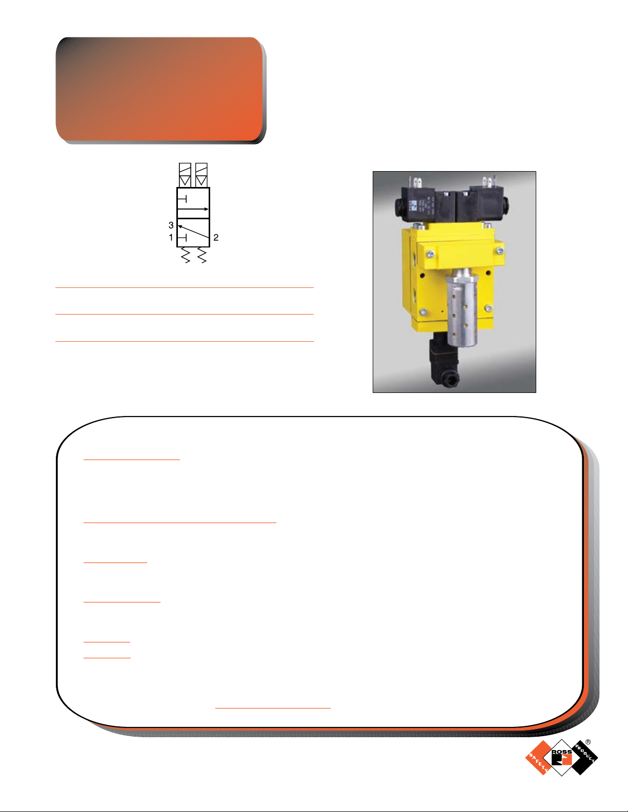
Control Reliable
Double Valve
with Dynamic Monitoring
Size 2
This valve is not designed for controlling clutch/brake mechanisms on mechanical power presses.
FEATURES:
Dynamic Monitoring:• Monitoring and air flow control functions are integrated into two identical valve elements
for CAT 3 applications. The valve exhausts downstream air if asynchronous movement of valve elements occurs
during actuation or de-actuation, resulting in a residual outlet pressure of less than 1% of supply. If the abnormality
clears itself, the valve will return to the ready-to-run state; there is no memory of the abnormal behavior, as in
ROSS’ DM
Basic 3/2 Normally Closed Valve Function:• Dirt tolerant, wear compensating poppet design for quick response
and high flow capacity. Teflon back-up rings on pistons to enhance valve endurance – operates with or without
inline lubrication.
Ready-to-run:• If an abnormality clears itself upon the removal of electricity to both solenoids, it will be ready-to-
run again. It does not remember the abnormality & stay in a locked-out state until intentionally reset. Therefore,
cumulative abnormalities may go undetected.
Status Indicator:• The above products include a pressure switch with both NO & NC contacts to provide status
feedback to the control system indicating whether the valve is in the “ready-to-run” condition or has experienced
abnormal function. This indicator only reports status it is not part of a lockout function.
Silencers:• All models include high flow, clog resistant silencers.
Mounting:• Inline mounted – with BSPP or NPT pipe threads. Inlet and outlet ports on both sides provide for
flexible piping (plugs for unused ports included).
2®
Series E and DM
2®
Series C products that require an intentional reset following lockout.
APPLICATIONS:
Category 3 applications - e.g. Air Dump/Release.
www.rosscontrols.com
Page 2
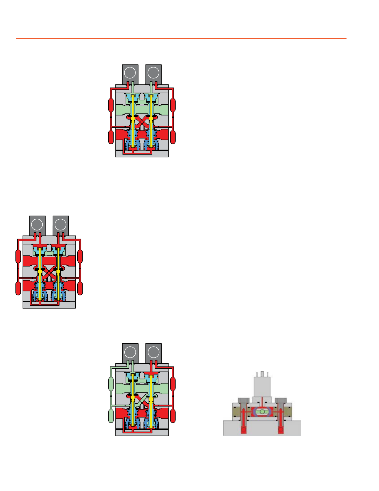
Overview of DM1 Series E Double Valve Function
.004
.004
.004
B
A
EXHAUST
OUTLET
INLET
B
A
EXHAUST
OUTLET
INLET
B
A
EXHAUST
OUTLET
INLET
Valve de-actuated
(ready-to-run):
The flow of inlet air pressure
into the crossover passages
fr om the i nlet cha mber is
restricted by orifices that allow
air pressure to bypass the lower
inlet poppets. Flow is sufficient
to quickly pressurize the pilot
supply/timing chambers on both
sides A and B. The upper inlet
poppets prevent air flow from
the crossover passages into the
outlet chamber. Air pressure
acting on the inlet poppets and
return pistons securely hold
the valve elements in the deactuated position. (Internal air
passages shown out of the valve
body for clarity.)
Valve actuated:
Energizing the pilot solenoids
simultaneously applies pressure
to both pistons, forcing the
internal parts to move to their
actuated position, where inlet
air flow to outlet is open and
both exh aust poppets are
closed. The outlet is then quickly
pressurized, and pressure in
the inlet, crossovers, outlet, and
timing chambers are quickly
equalized. De-energizing the
main solenoids causes the valve
Valve actuated.
elements to return to the readyto-run (de-actuated) position.
Asynchronous operation:
If the valve elements operate
in a sufficiently asynchronous
manner on ACTUATION, the
valve will shift into a position
where one crossover and its
related timing chambers will
be exhausted, and the other
crossover and its related timing
chambers will be pressurized.
In the illustration, side B is in the
de-actuated position, but has
no pilot air available to actuate
with and has full pressure on its
Valve ready-to-run.
Valve in restricted outlet
to exhaust state.
upper and lower inlet poppets and return piston to hold it in
place. Inlet air flow on side B into its crossover is restricted
and flows through the open upper inlet poppet on side A,
through the outlet into the the exhaust port, and from the
exhaust port to atmosphere. Residual pressure in the outlet
is less than 1% of inlet pressure.
Once the main solenoids are de-energized, actuating pressure
is removed from the top of the main pistons and then the
lower inlet poppet return spring along with inlet air pressure
acting on the side A return piston will push side A back into
the de-actuated position. Inlet air pressurizes the crossovers
and volume chambers. Pressure in the crossovers helps
hold the upper inlet poppets on seat. The valve will then be
in the ready-to-run position. On the next attempt to actuate
normally, if side B is still unable to actuate synchronously
with side A, the same sequence of events described above
will occur again.
WARNING:
If asynchronous operation occurs while DE-ACTUATING,
the pilot supply/timing chambers on one side will still be
exhausted as described above. However, this could be a
temporary situation because the cause of the asynchronous
operation may be able to correct itself allowing the stuck or
slow acting side of the valve to eventually move back into
the de-actuated position. Once the slow or stuck side has
de-actuated, the pilot supply/timing chambers that were
exhausted will then repressurize. If an external monitoring
system is only checking the status indicator periodically this
fault signal could be missed. The machine’s safety system
must be designed to ensure that this does not cause a
hazardous situation.
Status indicator:
The status indicator pressure switch will actuate when the
main valve is operating normally, and will de-actuate when
the main valve operation is sufficiently asynchronous or inlet
pressure is removed. This device is not part of the valve
lock-out function, but, rather, only reports the status of the
main valve.
Status indicator in normal
ready-to-run position.
ROSS CONTROLS
®
Page 3
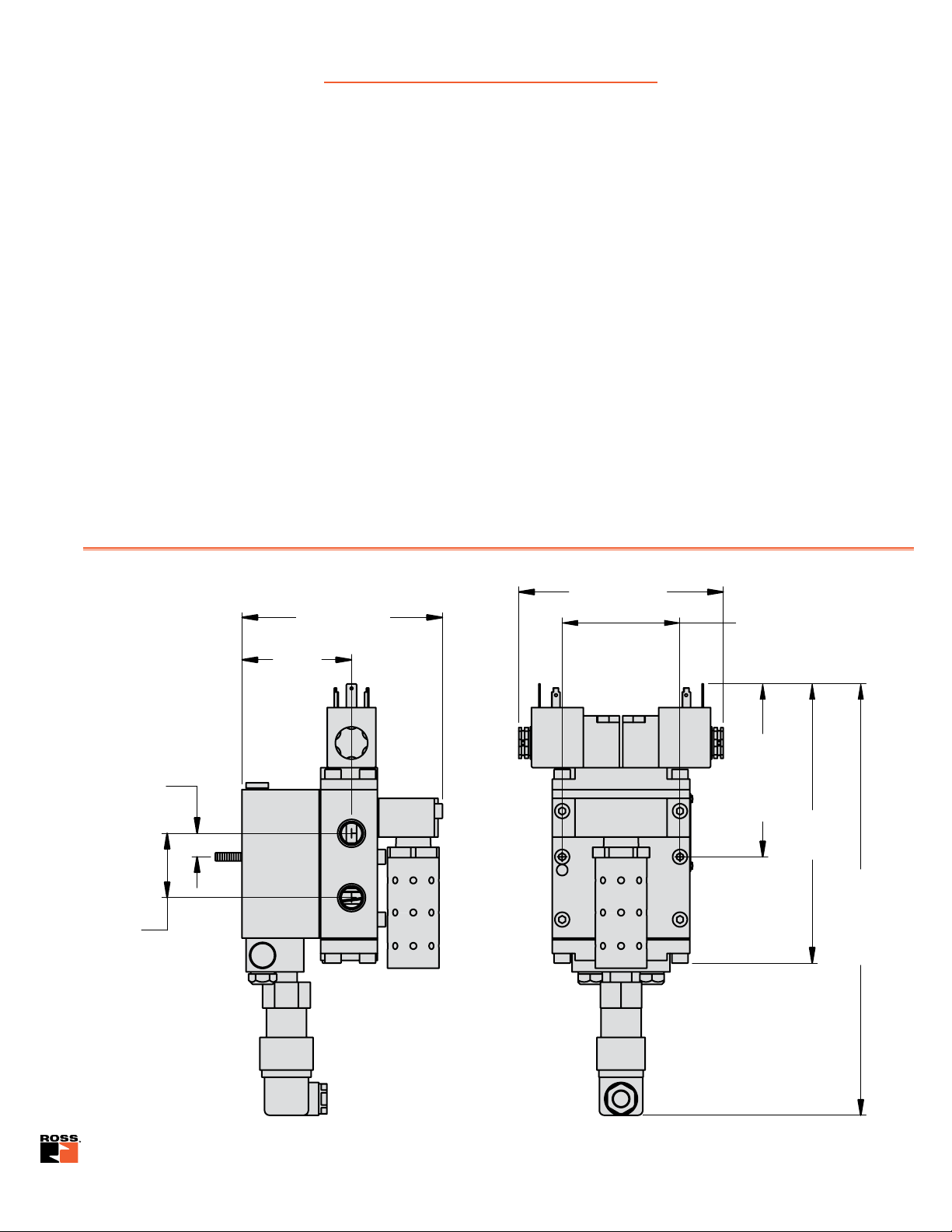
STANDARD SPECIFICATIONS
1
2
4.87 (123.6)
2.66
(67.6)
.57
(14.5)
1.56
(40.0)
4.96 (126.1)
2.87 (72.6)
Valve Mounting Pattern
4.20
(106.6)
Valve
Mounting
Pattern
6.77
(172.0)
10.46
(265.7)
with
Status
Indicator
Pilot Solenoid Power Consumption (each solenoid): 6.0 watts on DC; 15.8 VA inrush and
10.4 VA holding on AC.
Solenoids: According to VDE 0580. Enclosure rating according to DIN 400 50 IP 65.
Connector socket according to DIN 43650 Form A. Three solenoids, rated for continuous duty.
Standard Voltages: 110 volts AC, 50/60 Hz; 24 volts DC.
Temperature Range:
Ambient: 15° to 122°F (4° to 50°C).
Media: 40° to 175°F (4° to 80°C).
Flow Media: Filtered (5 micron recommended), lubricated or unlubricated air (mineral oils
according to DIN 51519, viscosity classes 32-46).
Inlet Pressure: 30 to 116 psig (2 to 8 bar).
Pressure Switch (Status Indicator) Rating: Contacts - 5 amps at 250 volts AC, or 5 amps at
30 volts DC.
DIMENSIONS – inches (mm)
www.rosscontrols.com
Page 4
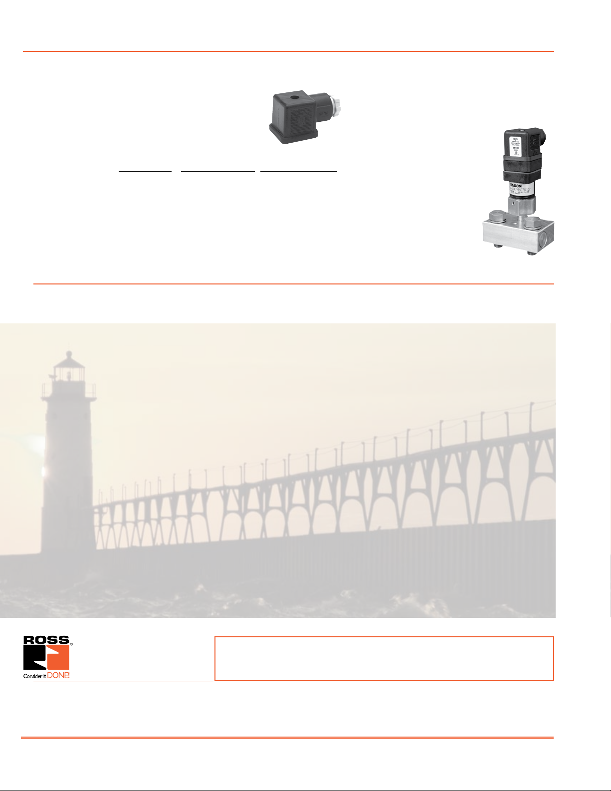
ACCESSORIES
ELECTRICAL CONNECTORS
Wired connectors have a 2-meter (6½ ft) cord with three
18-gauge conductors. Cord is available in either 6-mm
or 10-mm diameter and with or without indicator light.
Without Light With Light 24 VDC With Light 110 VAC
Wired with 6-mm cord 721K77 720K77-W 720K77-Z
Wired with 10-mm cord 371K77 383K77-W 383K77-Z
For threaded conduit 723K77 724K77-W 724K77-Z
For use with drop cord 937K87 936K87-W 936K87-Z
(cord not included)
For additional wiring kit accessories, please see Form NPS011 available at
www.rosscontrols.com.
Company Information
STATUS INDICATOR
The Status Indicator pressure switch
actuates when the valve is in a ready-to-run
condition and de-actuates
when the valve is in a
lockout condition or when
the inlet air pressure has
been removed.
Although, the valves can
be purchased with this
option already installed,
the Status Indicator can
be purchased separately
by ordering part number:
Y670B94.
ROSS EUROPA GmbH
Germany
Fax: 49-6103-74694
info@rosseuropa.com
Since 1921 ROSS CONTROLS® has been manufacturing the highest quality
pneumatic valves. Founded by three families and still privately held, Ross has
grown from a small Michigan valve company into a company with global subsidiaries
and distribution throughout the world. It is this global presence that allows Ross
to focus on specific industries and provide the support required in our integrated
world. Ross continues to lead in industries such as safety by providing products to
meet or exceed the specific requirements of those industries as well as the global
standards.
Our global safety team can assist with system and product selection and provide
solutions that help customers standardize globally.
ROSS CONTROLS
Customer Svs. 1-800-GET-ROSS
Technical Svs. 1-888-TEK-ROSS
ROSS ASIA
Fax: 81-427-78-7256
custsvc@rossasia.co.jp
U.S.A.
www.rosscontrols.com
®
K.K.
Japan
®
ROSS UK Ltd.
United Kingdom
Fax: 44-121-559-5309
sales@rossuk.co.uk
WARRANTY and CAUTIONS
Standard ROSS warranty and cautions apply, available upon request or at
www.rosscontrols.com.
®
ROSS CONTROLS
Fax: 91-44-2625-8730
rossindia@airtelbroadband.in
INDIA Pvt. Ltd.
India
ROSS SOUTH AMERICA Ltda.
Brazil
Fax: 55-11-4335-3888
vendas@ross-sulamerica.com.br
DIMAFLUID s.a.s.
France
Fax: 33-01-4945-6530
dimafluid@dimafluid.com
ROSS CONTROLS
Fax: 86-21-6915-7960
alvinzhurong@vip.163.com
(CHINA) Ltd.
China
Printed in the U.S.A. – Rev. 05/09 © 2009 ROSS CONTROLS®. All Rights Reserved. Form NPS006
 Loading...