

Page 1
SERIES W64 POPPET VALVES – Solenoid Control
ISO 5599/I - Drop Cord Connections
42
13
5
42
13
5
12
STANDARD SPECIFICATIONS
Solenoids: Rated for continuous duty.
Standard voltages: 100–110 volts 50 Hz.; 100–120
volts 60 Hz.; 24, 110 volts d.c.
Power Consumption: 8.5 VA inrush; 6 VA holding
on 50 or 60 Hz.; 6 watts on d.c.
Ambient Temperature: 40 to 120° F (4 to 50° C);
High temperature models: 40 to 175° F (4 to 80° C).
Media Temperature: 40 to 175° F (4 to 80° C); High
temperature models: 40 to 220° F (4 to 105° C).
Flow Media: Filtered air.
1214
Inlet Pressure: 30 to 150 psig (2 to 10 bar).
Pilot Pressure: Must be equal to or greater than
inlet pressure.
14
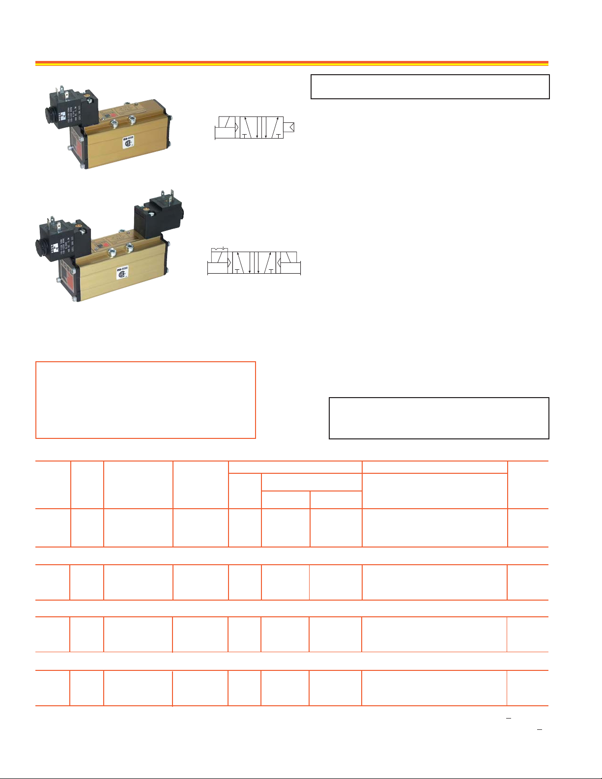
5/2 Single Solenoid Pilot Valve
5/2 Double Solenoid Pilot Valve
**VALVE RESPONSE TIME (msec) = M + (F • V)
Aver age time required to fill volume V (cubic inches)
to 90% of supply pressure or to exhaust it to 10%
of supply pressure. M and F values are shown in
charts for each valve. See discussion of Valve
Response Time on page 22.
5/2 SINGLE SOLENOID PILOT VALVES
Avg. Response Constants** Dimensions inches (mm)
Avg.CvISO
Size
1.0
2.1
4.0
1.0
2.1
4.0
1.0
2.1
4.0
1
2
3
1
2
3
1
2
3
Valve Model
Number
§
W6476B2401
W6476B3401
W6476B4401
W6476B2407
W6476B3407
W6476B4407
W6476B2402
W6476B3402
W6476B4402
HIGH TEMPERATURE 5/2 SINGLE SOLENOID PILOT VALVES
Port
Sizes*
1/8 – 3/8
3/8 – 1/2
1/2 – 3/4
M
33
33
50
5/2 DOUBLE SOLENOID PILOT VALVES
1/8 – 3/8
3/8 – 1/2
1/2 – 3/4
1/8 – 3/8
3/8 – 1/2
1/2 – 3/4
16
16
16
33
33
50
2.9
1.2
0.7
2.9
1.2
0.7
2.9
1.2
0.7
OPTIONS
Sub-Bases & Manifolds: Page 14.
Connectors, Electrical: Page 15.
Regulators, Interposed: Page 15.
Locking Overrides: See note below.
GM PS-1 models with 3-pin mini-connectors: See
note below .
IMPORTANT NOTE
Please read carefully and thoroughly the
CAUTIONS on page 23.
F
Out-Exh.In-Out
5.9
2.3
1.2
5.6
2.3
1.1
5.9
2.3
1.2
Length Width
5.6 (142)
6.3 (160)
6.4 (163)
6.9 (175)
7.7 (196)
6.4 (163)
5.6 (142)
6.3 (160)
6.4 (163)
1.7 (42)
2.1 (54)
2.6 (65)
1.7 (42)
2.1 (54)
2.6 (65)
1.7 (42)
2.1 (54)
2.6 (65)
§
Height
4.4 (112)
4.7 (119)
4.9 (124)
4.4 (112)
4.7 (119)
4.9 (124)
4.4 (112)
4.7 (119)
4.9 (124)
†
Weight
lb (kg)
1.3 (0.6)
1.8 (0.8)
2.8 (1.3)
1.8 (0.8)
2.3 (1.1)
3.3 (1.5)
1.3 (0.6)
1.8 (0.8)
2.8 (1.3)
HIGH TEMPERATURE 5/2 DOUBLE SOLENOID PILOT VALVES
1.0
2.1
4.0
§
Models with locking overrides can be ordered by changing the 9th digit of model number to “1”. For example, W6076B2411.
For models with 3-pin mini-connectors that conform to G.M. PS-1 standards, change the 9th digit to “3”. For example, W6076B2431.
* Port sizes determined by customer’s choice of base or manifold. Bases and manifolds sold separately – see page 14.
†
Height of valve with electrical connector installed. Connectors sold separately – see page 15.
12
1
2
3
W6476B2408
W6476B3408
W6476B4408
1/8 – 3/8
3/8 – 1/2
1/2 – 3/4
16
16
16
2.9
1.2
0.7
ROSS CONTROLS
5.6
2.3
1.1
®
6.9 (175)
7.7 (196)
6.4 (163)
1.7 (42)
2.1 (54)
2.6 (65)
4.4 (112)
4.7 (119)
4.9 (124)
1.8 (0.8)
2.3 (1.1)
3.3 (1.5)
Page 2
SERIES W64 POPPET VALVES – Pressure Control
ISO 5599/I
42
13
5
42
13
5
12
STANDARD SPECIFICATIONS
Ambient/Media Temperature Range: 40 to 175° F
(4 to 80° C).
High temperature models: 40 to 220° F (4 to 105° C).
Flow Media: 5 micron filtered air .
Inlet Pressure: Vacuum to 150 psig (10 bar).
Pilot Pressure: At least 30 psig (2 bar).
12
OPTIONS
Sub-Bases & Manifolds: Page 14.
Regulators, Interposed: Page 15.
14
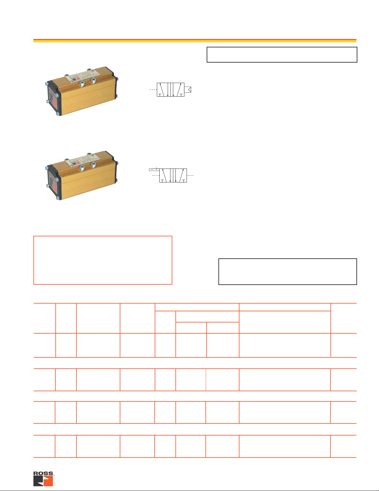
5/2 Single Remote Pilot Valve
14
5/2 Double Remote Pilot Valve
**VALVE RESPONSE TIME (msec) = M + (F • V)
Aver age time required to fill volume V (cubic inches)
to 90% of supply pressure or to exhaust it to 10%
of supply pressure. M and F values are shown in
charts for each valve. See discussion of Valve
Response Time on page 22.
5/2 SINGLE REMOTE PILOT VALVES
Avg. Response Constants** Dimensions inches (mm)
Avg.CvISO
Size
1.0
2.1
4.0
1.0
2.1
4.0
1.0
2.1
4.0
1
2
3
1
2
3
1
2
3
Valve Model
Number
W6456B2411
W6456B3411
W6456B4411
W6456B2417
W6456B3417
W6456B4417
W6456B2412
W6456B3412
W6456B4412
Port
Sizes*
1/8 – 3/8
3/8 – 1/2
1/2 – 3/4
5/2 DOUBLE REMOTE PILOT VALVES
1/8 – 3/8
3/8 – 1/2
1/2 – 3/4
HIGH TEMPERATURE 5/2 SINGLE REMOTE PILOT VALVES
1/8 – 3/8
3/8 – 1/2
1/2 – 3/4
M
33
33
50
16
16
16
33
33
50
2.9
1.2
0.7
2.9
1.2
0.7
2.9
1.2
0.7
IMPORTANT NOTE
Please read carefully and thoroughly the
CAUTIONS on page 23.
F
Out-Exh.In-Out
5.9
2.3
1.2
5.6
2.3
1.1
5.9
2.3
1.2
Length Width Height
4.4 (110)
5.1 (130)
6.4 (163)
4.4 (110)
5.1 (130)
6.4 (163)
4.4 (110)
5.1 (130)
6.4 (163)
1.7 (42)
2.1 (54)
2.6 (65)
1.7 (42)
2.1 (54)
2.6 (65)
1.7 (42)
2.1 (54)
2.6 (65)
1.8 (47)
2.1 (54)
2.3 (59)
1.8 (47)
2.1 (54)
2.3 (59)
1.8 (47)
2.1 (54)
2.3 (59)
Weight
lb (kg)
0.8 (0.4)
1.3 (0.6)
2.3 (1.1)
0.8 (0.4)
1.3 (0.6)
2.3 (1.1)
0.8 (0.4)
1.3 (0.6)
2.3 (1.1)
HIGH TEMPERATURE 5/2 DOUBLE REMOTE PILOT VALVES
1.0
2.1
4.0
* Port sizes determined by customer’s choice of base or manifold. Bases and manifolds sold separately – see page 14.
1
2
3
W6456B2418
W6456B3418
W6456B4418
1/8 – 3/8
3/8 – 1/2
1/2 – 3/4
16
16
16
2.9
1.2
0.7
5.6
2.3
1.1
4.4 (110)
5.1 (130)
6.4 (163)
1.7 (42)
2.1 (54)
2.6 (65)
1.8 (47)
2.1 (54)
2.3 (59)
0.8 (0.4)
1.3 (0.6)
2.3 (1.1)
13www.rosscontrols.com
Page 3

SUB-BASES and MANIFOLDS for ISO 5599/I VALVES
SUB-BASE NUMBERS and PORT SIZES
ISO
Size
1
2
3
Side
Ported
654K91
600C01
D600C01
642K91
601C01
D601C01
643K91
602C01
D602C01
644K91
Bottom
Ported
–
659K91
–
–
660K91
–
–
661K91
–
–
C
L
HH
42
I
I
1, 2, 4
1/8
1/4
G1/4
3/8
3/8
G3/8
1/2
1/2
G1/2
3/4
Port Sizes
3, 5
1/4
1/4
G1/4
3/8
3/8
G3/8
1/2
1/2
G1/2
3/4
D
12 14
M
12, 14
1/8
1/8
G1/8
1/8
1/8
G1/8
1/8
1/8
G1/8
1/8
K
In addition to the manifold stations, an end station kit must
be ordered for each manifold installation. End-ported stations
are assemblies consisting of a bottom-ported station and an
end-ported adaptor plate. Adaptor plates are cross-hatched in the
drawings below.
MANIFOLD NUMBERS and PORT SIZES
C
L
ISO
Size
1
2
3
P
N
N
Bottom
Ported
Station
460K91
D460K91
461K91
D461K91
462K91
D462K91
5
1
3
C
L
End
Ported
Station
664K91
D664K91
665K91
D665K91
666K91
D666K91
F
End
Station
Kit
326K86
D326K86
327K86
D327K86
328K86
D328K86
5
1
3
Port Sizes
2, 4
G1/4
G3/8
G1/2
1/4
3/8
1/2
1, 3, 5
3/8
G3/8
1/2
G1/2
1
G1
K
J
12, 14
1/8
G1/8
1/8
G1/8
1/8
G1/8
I
5
G
H
1
O
H
G
3
L
C
L
35
G
1
F
F
B
Sub-base Dimensions inches (mm)
ISO 1
1.89
4.33
1.26
0.41
0.85
0.85
0.39
0.47
1.14
0.94
0.93
3.86
0.22
(48)
(110)
(32)
(11)
(22)
(22)
(10)
(12)
(29)
(24)
(24)
(98)
(6)
A
B
C
D
E
F
G
H
I
J
K
L
M
* 1.77 (45) on sub-base 644K91.
ISO 2 ISO 3
2.24
(57)
4.88
(124)
1.57
(40)
0.55
(14)
1.02
(26)
1.10
(28)
0.51
(13)
0.59
(15)
1.46
(37)
1.12
(29)
1.18
(30)
4.41
(112)
0.26
(7)
14
2.80
5.87
1.26
0.67
0.67
1.34
0.71
0.63
1.77
1.40
0.87
5.35
0.26
J
D
A
E
(71)
(149)
(32)*
(17)
(17)
(34)
(18)
(16)
(45)
(36)
(22)
(136)
(7)
C
ACCESSORIES and
OPTIONS for MANIFOLDS
Blank Station Kits, Blocking
Discs, Pressure Plates,
Transition Plates and other
available options are shown
on page 15.
ROSS CONTROLS
DE
A
C
L
ML
BC
NOTE: Lined portions of
12 12
S
4
R
Q
2
4
2
drawings are end-ported
adaptors which are included
only with end-ported stations.
TT
Manifold Dimensions inches (mm)
ISO 1
5.12
0.87
1.69
0.30
0.06
4.25
0.55
0.94
0.83
0.94
1.81
0.33
0.85
0.51
4.33
0.27
0.47
0.98
3.19
0.43
(130)
(22)
(43)
(8)
(2)
(108)
(14)
(24)
(21)
(24)
(46)
(9)
(22)
(13)
(110)
(7)
(12)
(25)
(81)
(11)
A
B
C
D
E
F
G
H
I
J
K
L
M
N
O
P
Q
R
S
T
A and F dimensions are for a 2-station manifold.
For each additional station add the C dimension
to obtain new A and F dimensions.
®
ISO 2 ISO 3
6.46
1.02
2.20
0.24
0.20
5.43
0.69
1.24
0.87
0.94
1.85
0.35
1.10
0.59
5.31
0.35
0.55
1.02
3.54
0.57
(164)
(26)
(56)
(138)
(18)
(32)
(22)
(24)
(47)
(28)
(15)
(135)
(14)
(26)
(90)
(15)
(6)
(5)
(9)
(9)
7.95
1.18
2.80
0.31
0.24
6.77
1.02
1.85
1.22
1.34
2.20
0.39
1.40
0.75
7.48
0.47
0.67
1.14
3.90
0.71
(202)
(30)
(71)
(8)
6)
(172)
(26)
(47)
(31)
(34)
(56)
(10)
(36)
(19)
(190)
(12)
(17)
(29)
(99)
(18)
Page 4

ACCESSORIES for ISO 5599/I VALVES
CONNECTORS for use with
DROPCORDS
Electrical connectors are required to
connect the valve solenoids to the
dropcords supplying electrical power.
Each connector can be oriented so that the cord can exit in
any one of four directions: outboard, inboard, and to the
right or to the left of the valve centerline. Cords of 6-mm to
10-mm diameter can be used.
Indicator Lights. Lights in connectors with a translucent
housing can be used as indicator lights to show when solenoids are energized.
Wired Connectors. Connectors have a 6-1/2- ft (2-meter)
cord with three 18-gauge conductors. Cord exits outboard
as shown at the right. Insulation is water , oil, and abrasion
resistant. Connectors are available with 10-mm cords for
maximum abrasion resistance, or with 6-mm cords where
added flexibility or small diameter is required.
CONNECTORS for use with THREADED CONDUIT
Connectors similar to those above but threaded to accept
1/2-inch electrical conduit fittings are also available.
FLYING SOLENOID LEADS
Instead of the connectors described, power to the solenoids
can also be supplied via “flying leads.” These are 18-gauge
insulated wires with spade connectors at one end. A kit of
flying leads consists of three wires, each 39 inches (one
meter) long. Order by kit number 725K77.
PART NUMBERS of ELECTRICAL CONNECTORS
Connector Type
For use with drop cord
(Cord not included)
Wired with 6-mm cord
Wired with 10-mm cord
For use with
threaded conduit
* Specify solenoid voltage.
Without
Light
937K87
721K77
371K77
723K77
With
Light*
936K87
720K77
383K77
724K77
BLANK STATION KITS
A blank station plate is used to cover the top of a manifold
station that is not in use. A kit consists of a metal plate 0.32
inch (8mm) thick, a gasket, and mounting bolts.
ISO Size 1: 546H77
ISO Size 2: 694K77
ISO Size 3: 537H77
TRANSITION PLATES
Different size ISO valv es can be used in the same manifold
installation by means of transition plates. The inlet and exhaust ports of two different size manifold stations are connected by means of a transition plate installed between the
two stations Thic kness [inches (mm)] of the plates is shown
below.
ISO Size 1 to 2 - 0.79 (20): D355K86
ISO Size 2 to 3 - 1.26 (32): D356K86
ISO Size 1 to 3 - 1.26 (32): D357K86
INTERPOSED FLOW CONTROLS for SPOOL VALVES
An interposed flow control unit regulates the exhaust flow
of air from a pneumatic cylinder, thereby controlling the e xtension and retraction speeds. Separate controls regulate
the air flow from each end of the cylinder. Being located
between the valve and base, the unit requires no additional
piping. A vailable only f or Series W60 and W63 spool v alves.
ISO Size 1: 701B77
ISO Size 2: 702B77
ISO Size 3: 722K77
INDEPENDENT PRESSURE PLATES
When a valve in a manifold installation must work at a different pressure than that supplied to the manifold, an independent supply can be provided via an independent pressure plate. The pressure plate mounts between valve and
base and isolates the valve from the manifold inlet pressure. The independent supply is connected to an inlet port
in the end of the pressure plate.
ISO Size 1 (1/4 inlet port): 703K77
ISO Size 2 (3/8 inlet port): 692K77
ISO Size 3 (1/2 inlet port): 715K77
BLOCKING DISKS
Ports between manifold stations can be closed by means of
blocking disks.
Single Disk Kit of 3 Disks
ISO Size 1: 235A40 1007K77
ISO Size 2: 236A40 1008K77
ISO Size 3: 253A40 1009K77
INTERPOSED PRESSURE REGULATORS
Both single and double pressure regulators are available.
Single pressure regulators provide the same regulated pressure at both outlet ports.
Double pressure regulators allow the pressure at each outlet
port to be set independently.
Pressure can be regulated from
5 to 100 psig (0.3 to 7 bar) for
ISO sizes 1 and 2;
A
Single Regulator
5 to 125 psig (0.3 to
8.5 bar) for ISO size
3. Maximum inlet
pressure is 150 psig
(10 bar). Requires
no new piping.
Double Regulator
Double**
ISO Size
1
2
3
**Double regulators only for series W60 and W63 spool valves.
Regulator Dimensions - inches (mm)
ISO Size
1
2
3
Single
620C91
624C91
628C91
A
(Single)
7.75 (197)
8.25 (210)
12.70 (323)
(Solenoid)
621C91
625C91
629C91
A
(Double)
12.90 (328)
13.60 (346)
20.00 (508)
A
Double**
(Air)
710C91
711C91
712C91
B
(Single/Double)
2.50 (64)
2.90 (74)
3.78 (96)
B
B
15www.rosscontrols.com
 Loading...