

Page 1
CHECK
VALVE
CHECK
VALVE
C1
C1
Pilot Pilot
V1 V1
OPERATING
VALVE
ExhaustExhaust
CYLINDER
B
C
A
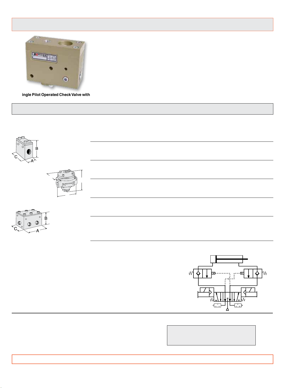
Series 27 Pilot Operated Check Valves
• Can be used wherever a high-flow or remotely-controlled checking
function is needed.
• Can be used in a circuit to provide automatic stopping of a cylinder
in the event of the loss of electrical or pneumatic power.
• Also available with an automatic exhausting function, remote and
manual trapped pressure relief function, or solenoid dual pilot
operated check.
Single Pilot Operated Check Valve with
trapped pressure relief illustrated
Pressure Controlled Pilot Operated Check Valves
WITHOUT Trapped Pressure Relief Function
Valve Port Valve Model Avg. CV Dimensions inches (mm) Weight
Type Size Number
Type A Single
PO Check Valve
Ports: 1/4 through 1/2
Type B Single
PO Check Valve
Ports: 1/4 through 1½
Type C Dual
PO Check Valve
Ports: 3/8 through 1
1/4 2751A2908 2.2 1.5 (38) 3.6 (91) 2.0 (51) 2.3 (1.0)
A 3/8 2751A3908 2.9 1.5 (38) 3.6 (91) 2.0 (51) 2.3 (1.0)
1/2 2751A4915 3.2 1.5 (38) 3.6 (91) 2.5 (64) 2.3 (1.0)
1/4 2751A2903 2.3 3.6 (91) 3.8 (95) 3.1 (79) 1.3 (0.6)
B 3/8 2751A3901 3.8 3.6 (91) 3.8 (95) 3.1 (79) 1.3 (0.6)
1/2 2751A4902 4.0 3.6 (91) 3.8 (95) 3.1 (79) 1.3 (0.6)
1/2 2751A4905 7.7 4.6 (116) 4.4 (112) 3.1 (79) 2.3 (1.0)
B 3/4 2751A5903 9.0 4.6 (116) 4.4 (112) 3.1 (79) 2.3 (1.0)
1 2751A6901 9.0 4.6 (116) 4.4 (112) 3.1 (79) 2.3 (1.0)
1 2751B6904 24 6.7 (169) 6.5 (165) 4.1 (104) 6.0 (2.7)
B 1¼ 2751B7901 29 6.7 (169) 6.5 (165) 4.1 (104) 6.0 (2.7)
1½ 2751B8902 29 6.7 (169) 6.5 (165) 4.1 (104) 6.0 (2.7)
3/8 2768C3900 2.9 3.4 (89) 3.7 (94) 2.4 (61) 2.0 (0.9)
C 1/2 2768C4900 3.2 3.4 (89) 3.7 (94) 2.4 (61) 2.4 (1.1)
Dual 3/4 2768C5900 8.5* 4.4 (111) 4.1 (104) 3.0 (76) 3.8 (1.7)
1 2768A6900 8.5* 5.8 (147) 4.1 (104) 3.9 (99) 6.8 (3.1)
*Effective CV varies with load and pressure drop. Consult ROSS for specifics on your system.
(Fully open) A B C lb (kg)
TYPICAL APPLICATION
In the schematic diagram at the right, two single PO check valves (Type A or B) are
used in a typical cylinder circuit. Their function is to provide automatic stopping of
the cylinder if either electrical or pneumatic power is lost. This circuit can also be
used for jogging the cylinder as well as providing for an emergency stop.
In certain port sizes the two check valves could be replaced by just one Type C dual
PO check valve. The dual PO check valve contains the functions of two individual
checks in a single compact housing, and eliminates the need to connect externally
the inlet of one check to the pilot of the other.
STANDARD SPECIFICATIONS: For valves on this page.
Ambient/Media Temperature: 40° to 175°F (4° to 80°C).
Flow Media: Filtered air; 5 micron recommended.
Inlet Pressure: 15 to 150 psig (1 to 10 bar).
Signal Pressure: Must be equal to or greater than inlet.
Port Threads: NPT standard, BSPP. For BSPP threads add a
“D” prefix to the model number, e.g., D2751A2908.
2 © 2009, ROSS CONTROLS®.
IMPORTANT NOTE: Please read carefully and thoroughly all of the CAUTIONS on page 11.
PIPING NOTE FOR TYPE B VALVES
Port 1 should be piped to the cylinder,
and port 2 to the operating valve.
All Rights Reserved.
Page 2
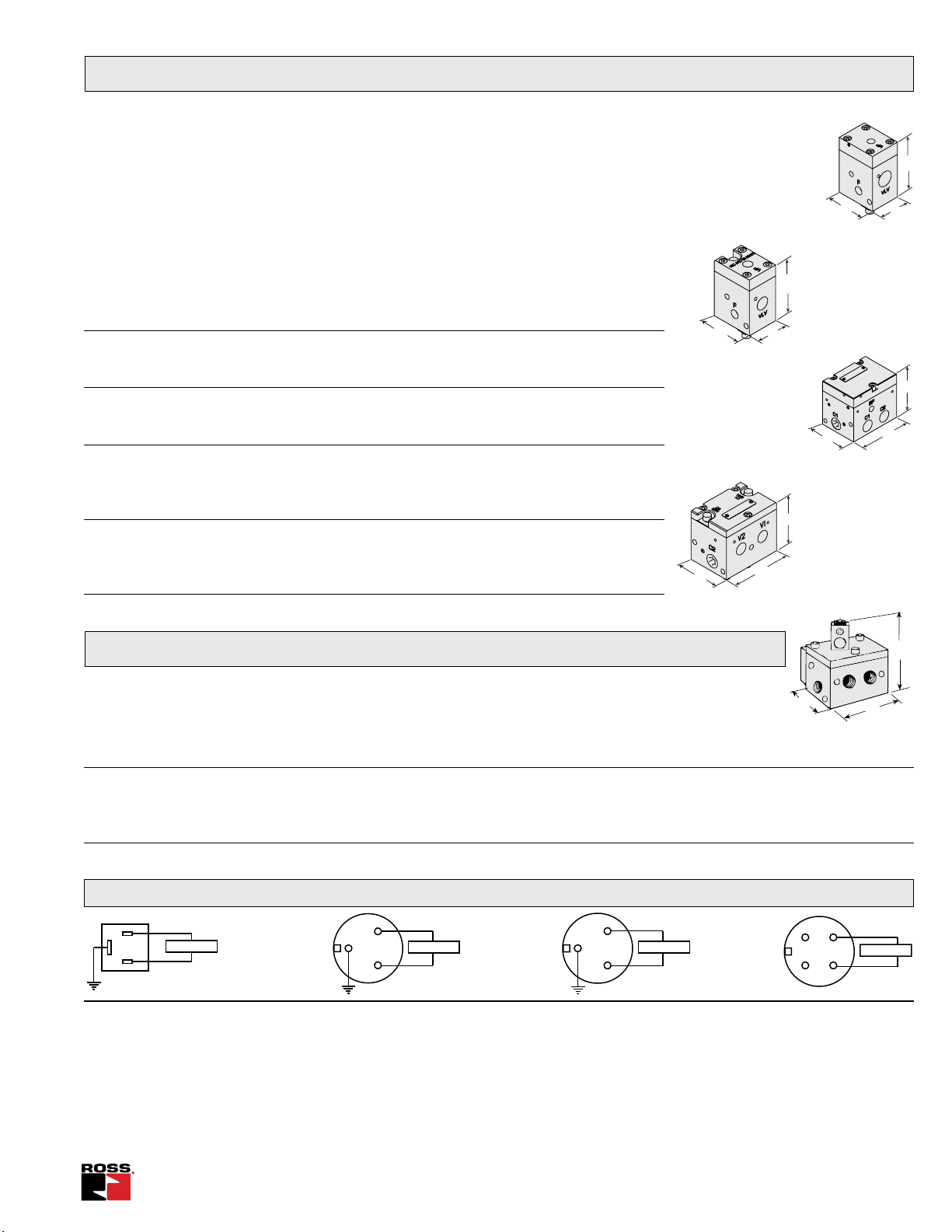
Pressure Controlled Pilot Operated Check Valves
B
A
C
WITH Trapped Pressure Relief Function
Air pilot or solenoid pilot operated check valves with trapped pressure relief can be used to control
a pneumatic cylinder in several important ways. For example:
• Maintaining a cylinder (horizontal or vertical) in a stationary position upon loss of electrical power.
• Jogging a cylinder.
• Relieving pressure trapped between check valve and cylinder.
Correct installation of a dual check valve is essential. It should be mounted as close to the cylinder
as possible. Minimizing the air volume by keeping the air lines short will reduce cylinder “bounce,”
and help to give the best performance.
Valve Port Valve Model Avg. CV Dimensions inches (mm) Weight
Type Size Number
(Fully open) A B C lb (kg)
3/8 2751B3922 2.6 1.65 (41.9) 3.57 (90.6) 2.2 (55.9) 1.8 (0.8)
A 1/2 2751B4922 2.8 1.65 (41.9) 3.57 (90.6) 2.2 (55.9) 1.8 (0.8)
Remote
3/4 2751B5917 9.2 4.3 (110) 4.2 (107) 2.2 (56) 2.9 (1.3)
3/8 2751B3920 2.6 1.65 (41.9) 3.47 (88) 2.2 (55.9) 1.8 (0.8)
A 1/2 2751B4920 2.8 1.65 (41.9) 3.47 (88) 2.2 (55.9) 1.8 (0.8)
Manual
3/4 2751B5919 9.2 4.3 (110) 4.2 (107) 2.2 (56) 2.9 (1.3)
3/8 2768D3901 2.9 3.6 (91.4) 3.64 (92.4) 2.6 (66.1) 3.5 (1.6)
D 1/2 2768D4901 3.2 3.6 (91.4) 3.64 (92.4) 2.6 (66.1) 3.5 (1.6)
Remote 3/4 2768D5901 8.5* 4.98 (126.5) 4.24 (107.7) 3.4 (86.4) 5.2 (2.3)
1 2768D6901 8.5* 4.98 (126.9) 4.24 (107.7) 3.4 (86.4) 8.8 (4.0)
3/8 2768D3904 2.9 3.6 (91.4) 3.6 (91.4) 2.6 (66.1) 3.2 (1.4)
D 1/2 2768D4904 3.2 3.6 (91.4) 3.6 (91.4) 2.6 (66.1) 3.5 (1.6)
Manual 3/4 2768D5904 8.5* 4.8 (122) 4.24 (107.7) 3.4 (86.4) 5.2 (2.3)
1 2768D6904 8.5* 4.8 (122) 4.24 (107.7) 3.4 (86.4) 8.8 (4.0)
*Effective CV varies with load and pressure drop. Consult ROSS for specifics on your system.
Type A Single
PO Check Valve
(Remote Trapped
Pressure Relief)
Ports: 3/8 through 3/4
B
Ports: 3/8 through 3/4
C
Type D Internal Pilot Dual
PO Check Valve
(Remote Trapped
Pressure Relief)
Ports: 3/8 through 1/2
C
A
Type D Internal Pilot
Dual PO Check Valve
B
Ports: 3/8 through 1/2
A
C
Type A Single
PO Check Valve
(Manual Trapped
Pressure Relief)
C
(Manual Trapped
Pressure Relief)
B
A
B
A
Solenoid Controlled Pilot Operated Check Valves
Type E Solenoid Pilot
Dual PO Check Valve
24 volts DC 24 volts DC
Valve Port Avg. DIN 3-Pin Mini 3-Pin Mini 4-Pin Micro Dimensions inches (mm) Weight
Type Size C
Connector Connector Connector Connector A B C lb (kg)
V
3/8 2.9 2778C3900 2778C3901 2778C3902 2778C3904 3.60 (91.4) 5.67 (144) 2.60 (66.1) 4.0 (1.8)
E 1/2 3.2 2778C4900 2778C4901 2778C4902 2778C4904 3.60 (91.4) 5.67 (144) 2.60 (66.1) 4.2 (1.9)
3/4 8.5* 2778C5900 2778C5901 2778C5902 2778C5904 4.98 (126.5) 6.77 (172) 3.40 (86.4) 6.1 (2.8)
1 8.5* 2778A6900 2778A6901 2778A6902 2778A6904 4.98 (126.5) 6.77 (172) 3.40 (86.4) 6.1 (2.8)
*Effective CV varies with load and pressure drop. Consult ROSS for specifics on your system.
Connector Wiring
3
1
SOLENOID
2
SOLENOID
DIN
Connector
AC Mini
Connector
STANDARD SPECIFICATIONS: For valves on this page.
INTERNAL PILOT MODELS:
Ambient/Media Temperature: 40° to 175°F (4° to 80°C).
Inlet Pressure: 15 to 150 psig (1 to 10 bar).
SOLENOID PILOT MODELS:
Solenoids: AC or DC power.
Standard Voltages:
24 volts DC; 3-pin Mini and 4-pin Micro connectors.
100-110 volts, 50 Hz; 100-120 volts, 60 Hz;
DC Mini
Connector
Power Consumption: 8 VA inrush, 6 VA holding on AC; on DC 4.5
watts with 4-pin Micro connector, 60 watts with 3-pin connector.
Ambient Temperature: 40° to 120°F (4° to 50°C).
Media Temperature: 40° to 175°F (4° to 80°C).
Flow Media: Filtered air; 5 micron recommended.
Inlet Pressure: 30 to 150 psig (2 to 10 bar).
Signal Pressure: Must be equal to or greater than inlet.
Port Threads: NPT standard, BSPP. For BSPP threads add a “D”
prefix to the model number, e.g., D2778D3900.
3
1
2
Ports: 3/8 through 1
Common
SOLENOID
+ 24VDC
DC Micro
Connector
4
1
2
3
+ 24 VDC
SOLENOID
Common
www.rosscontrols.com 3
Page 3

Cylinder
Cylinder
Single Pressure Controlled PO Check Valve Application
TYPICAL APPLICATIONS:
Horizontal or vertical long-stroke cylinders.
CIRCUIT FEATURES:
• Trapped pressure between check valve and cylinder is exhausted when the
air supply at the Blowdown Signal Port (BP) is lost or locked-out.
• Cylinder moves as long as the control valve solenoid is energized. Use for
With Trapped Pressure Relief
L-O-X (Lockout
& eXhaust Valve)
continuous motion or jogging.
• Cylinder remains stationary if neither control valve solenoid is energized, or
if electrical signal is lost.
• The single PO check with pressure relief have an additional 1/8” NPT port
provided for the installation of a pressure sensing device such as a pop-up
Single PO Check Valve
indicator or pressure switch. Standards suggest that machine design should
include a method for verifying the release of stored energy.
IMPORTANT NOTES and CAUTIONS:
» Cylinder movement may occur when inlet pressure is lost. The cylinder’s
movement is slowed only by the restrictions of the flow control valves, and
by the exhaust capacity of the check valve relief flow capacity.
» For best response, flow control valves should be installed between the check
valve and the cylinder.
» Pressurizing the system after supply air has been off may cause rapid movement
3-Position, Open-
Center Control Valve
Vertical
Cylinder
of the cylinder because cylinder air was exhausted while the supply air was off.
Dual Internal Pressure Controlled PO Check Valve Applications
TYPICAL APPLICATIONS: Horizontal or vertical long-stroke cylinders.
Remote Trapped Pressure Relief Manual Trapped Pressure Relief
Flow
Control
Valves
C1 C2
V1 V2
3-Position, OpenCenter Control Valve
Remote-controlled
Check Valve relief
Dual Check
Valve with
Internal Pilot
Holding
P
Pressure
®
L-O-X
Valve
CIRCUIT FEATURES:
• Trapped pressure between check valve and cylinder is exhausted
when the air supply at “P” port is lost or locked-out.
• Cylinder moves as long as a control valve solenoid is energized.
Use for continuous motion or jogging.
• Cylinder remains stationary if neither control valve solenoid is
energized, or if electrical signal is lost.
®
• L-O-X
valve provides lockable shutoff of air supply, and
exhausting of trapped downstream air.
IMPORTANT NOTES and CAUTIONS:
» Cylinder movement may occur when inlet pressure is lost. Its
movement is slowed only by the restrictions of the flow control
valves, and by the exhaust capacity of the check valve relief flow
capacity.
» For best response, flow control valves should be installed
between the check valve and the cylinder.
» Pressurizing the system after supply air has been off may
cause rapid movement of the cylinder because cylinder air
was exhausted while the supply air was off. See page 5 for
soft-startup circuit.
Flow
Control
Valves
C1 C2
V1 V2
3-Position, OpenCenter Control Valve
Manual-controlled
Check Valve relief
Internal Pilot
BA
L-O-X
Valve
Dual Check
Valve with
®
CIRCUIT FEATURES:
• Trapped pressure between check valve and cylinder is
exhausted when pushbuttons A and B are pressed.
• Cylinder moves as long as a control valve solenoid is energized.
Use for continuous motion or jogging.
• Cylinder remains stationary if neither control valve solenoid is
energized, or if electrical signal is lost.
®
• L-O-X
valve provides lockable shutoff of air supply.
IMPORTANT NOTES and CAUTIONS:
» Cylinder movement may occur if only one pushbutton (A or B)
is pressed. To exhaust fully both cylinder ports, push and hold
A and B simultaneously.
» For best response, flow control valves should be installed
between the check valve and the cylinder.
» Pressurizing the system after supply air has been off may
cause rapid movement of the cylinder. See page 5 for softstartup circuit.
NOTE: See Installation and Troubleshooting on page 6.
4 © 2009, ROSS CONTROLS®.
All Rights Reserved.
Page 4

Dual Solenoid Controlled PO Check Valve Application
V1 V2
2-Position
Control Valve
Cylinder
L-O-X
®
Valve
P
Holding
Pressure
Flow
Control
Valves
Dual Check
Valve with
Solenoid Pilot
C1 C2
EEZ-ON
®
Valve
Sol C
Sol A Sol B
V1 V2
3-Position
Open Center
Control Valve
Cylinder
L-O-X
®
Valve
P
Holding
Pressure
Flow
Control
Valves
Dual Check
Valve with
Solenoid Pilot
and Relief
Function
C1 C2
EEZ-ON
®
Valve
Sol C
External
Pilot
Supply
Sol A
Sol B
Cylinder
TYPICAL APPLICATIONS: Overhead lifter circuits; applications where there is
a long distance between the check valve and the operating valve.
Flow
Control
Valves
Sol C
C1 C2
Sol A Sol B
3-Position, OpenCenter Control Valve
V1 V2
Dual Check
Valve with
Solenoid Pilot
and Relief
Function
Holding
P
Pressure
®
L-O-X
Valve
CIRCUIT FEATURES:
• To operate cylinder, simultaneously energize solenoids A and C or B and C.
• Pilot supply and exhaust are independent of control valve. Response time is not affected
by exhaust restrictions of the control valve.
• Cylinder remains stationary if neither control valve solenoid is energized, or if electrical
signal is lost.
• Pressure in cylinder is exhausted when the air supply at “P” port is lost or locked-out.
®
• L-O-X
valve provides lockable shutoff of air supply, and exhausting of trapped
downstream air.
IMPORTANT NOTES and CAUTIONS:
» Cylinder movement may occur when inlet pressure is lost. Its movement is slowed
only by the restrictions of the flow control valves, and by the exhaust capacity of the
check valve relief flow capacity.
» The solenoid of the check valve must be wired so that it is energized whenever either
control valve solenoid is energized.
» Pressurizing the system after supply air has been off may cause rapid movement
of the cylinder because cylinder air was exhausted while the supply air was off. See
below for soft-startup circuit.
Dual PO Check Valve Applications with EEZ-ON® Valve for Soft Startup
With 2-Position Control Valve
With 3-Position Control Valve
TYPICAL APPLICATIONS:
Shuttle and lifter circuits; applications where there is a long distance
between the check valve and the operating valve; applications where
gradual cylinder movement upon pressurization is acceptable.
CIRCUIT FEATURES:
• Cylinder will remain fully extended or retracted if electrical
signal to control valve solenoid is lost.
• Pressure in the cylinder is exhausted when the air supply at
“P” port is lost or locked out.
• When the air supply is turned on, the EEZ-ON
(see page 6) allows slow pressurization of the system so
that the cylinder moves slowly into the fully extended or
retracted position.
• L-O-X
®
valve provides lockable shutoff of air supply, and
exhausting of trapped downstream air.
IMPORTANT NOTES and CAUTIONS:
» For cylinder to move, energizing of solenoids A and C or B and
C must occur simultaneously.
NOTE: See Installation and Troubleshooting on page 6.
www.rosscontrols.com 5
TYPICAL APPLICATIONS:
Shuttle and lifter circuits; applications where cylinder movement
upon pressurization is NOT acceptable.
CIRCUIT FEATURES:
• Regulators are set to compensate for differing areas on either
side of cylinder piston. Provides a steady startup and a gradual
stopping of the cylinder.
®
®
valve
• When the air supply is turned on, the EEZ-ON
page 6) allows pressure to build up on both sides of the piston.
valve (see
This minimizes startup “bounce.”
• Pilot operated check valve prevents drifting, and can be closecoupled to cylinder to reduce “bounce.”
• Pressure in the cylinder is exhausted when the air supply at
“P” port is lost or locked out.
®
• L-O-X
valve provides lockable shutoff of air supply, and
exhausting of trapped downstream air.
IMPORTANT NOTES and CAUTIONS:
» For cylinder to move, energizing of solenoids A and C or B and
C must occur simultaneously.
Page 5

Installation and Troubleshooting
ROSS
®
INSTALLATION
• Locate the check valve as close to the cylinder as possible.
This will minimize cylinder bounce and drift.
• Use non-expandable hose between check valve and cylinder.
The expandability of thin-wall flexible hose can magnify cylinder
bounce and drift.
• To install threaded pipe or fittings, engage threads one turn,
apply thread sealant (tape not recommended) to threads, and
tighten pipe or fitting fully.
• After system is pressurized, check all connections with soapy
water to ensure that there are no leaks. Drifting can occur if
leaks are present between the check valve and the cylinder.
Circuit for Control of Rodless Actuators
Rodless
Cylinder
Flow
Flow
Control
Valve
Control
Valves
3-Position,
Pressure Center
Control V alve
EEZ-ON
Valve
L-O-X
®
Valve
TYPICAL APPLICATIONS: Control of rodless cylinders, double-rod cylinders, air motors
on transfer systems, and part loaders.
CIRCUIT FEATURES:
• When the air supply is turned on, the EEZ-ON
the cylinder to provide soft start recharging.
• Allows cylinder to be jogged in either direction.
• L-O-X® valve (see below) provides lockable shutoff of supply air, and exhausting of
®
trapped downstream air.
• Prevents runaways due to loss of air pressure.
• Pressure at port P must be equal to or greater than the pressure
in the cylinder and greater than the minimum operating pressure
of the control valve.
• Do not restrict the exhaust of the control valve.
• In a circuit using a solenoid pilot check valve, the check valve
solenoid and a control valve solenoid must be energized
simultaneously.
TROUBLESHOOTING TIP
The most common cause of unsatisfactory performance is leaky
connections. Always check for leaks with before undertaking any
other repair procedures.
®
valve (see below) slowly pressurizes
Other ROSS Valves Used in the Circuits
EEZ-ON® Valves
An EEZ-ON® valve allows a gradual
buildup of downstream air pressure after
the supply is turned on. Rate of buildup
is adjustable. This controlled action lets
cylinders move slowly and more safely
into normal working positions.
A 3/2 EEZ-ON
which has a shutoff-andexhaust feature is also
available.
Port 2/2 Model Avg.
Size Number C
1/4 2781A2007 2.3
3/8 2781A3007 3.8
1/2 2781A4017 4.0
1/2 2781A4007 7.7
3/4 2781A5007 9.0
1 2781A6017 9.0
1 2781A6007 24
1¼ 2781A7007 29
1½ 2781A8017 29
®
valve
v
L-O-X® Valves
A ROSS L-O-X® valve is an energy isolation valve,
generally the first valve in the air supply line. Air
can be shut off with a push of the red handle, and
downstream air is exhausted at the same time. For
safety, the handle should be padlocked in the closed
position when system maintenance
is being performed.
Th e manu ally contr olled
®
valve is shown here,
L-O-X
but piloted models to control
the flow of air remotely are
also available.
Port Sizes L-O-X® Valve Avg. C
In-Out Exh. Model Numbers In-Out Out-Exh
1/4 1/4 Y1523C2002 1.9 1.9
3/8 3/8 Y1523C3012 2.5 2.6
3/8 3/4 Y1523C3002 6.0 8.0
1/2 3/4 Y1523C4002 7.1 8.3
3/4 3/4 Y1523C5012 8.6 9.5
3/4 1¼ Y1523C5002 13 12
1 1¼ Y1523C6002 13 14
1¼ 1¼ Y1523C7012 20 14
1½ 2 Y1523C8002 38 47
2 2 Y1523C9012 38 47
v
Flow Control Valves
A ROSS flow control valve provides a high
air flow rate into a cylinder, and a precisely
controlled flow rate out of the cylinder. The
adjustable flow can range from near zero
to full flow. A non-rising adjustment knob
turns clockwise to reduce controlled flow.
Flow control valves in
other configurations
are al s o ava i l a b l e
from ROSS.
Port Flow Control Avg. C
Size Model Numbers (Fully open)
1/4 1968E2007 2.3
3/8 1968E3007 2.6
1/2 1968E4007 7.5
3/4 1968E5007 8.3
1 1968E6007 17
1¼ 1968E7007 22
v
6 © 2009, ROSS CONTROLS®.
All Rights Reserved.
 Loading...