

Page 1

Maintenance Guide
Page 2

XPression Prime • Maintenance Guide
• Ross Part Number: 3503DR-006-01
• Release Date: November 22, 2012. Printed in Canada.
The information contained in this Guide is subject to change without notice or obligation.
Copyright
© 2012 Ross Video Limited. All rights reserved.
This work is proprietary and confidential to Ross Video Limited, its subsidiaries and its other affiliated corporations
and may not be copied, distributed, sold or otherwise used or relied upon without the express written permission of
Ross Video Limited. Reproduction or reverse engineering of copyrighted software is prohibited.
Notice
The material in this manual is furnished for informational use only. It is subject to change without notice and should
not be construed as commitment by Ross Video Limited. Ross Video Limited assumes no responsibility or liability
for errors or inaccuracies that may appear in this manual.
Trademarks
• is a registered trademark of Ross Video Limited.
• Ross, ROSS, ROSS
• Microsoft® and Windows® are registered trademarks of Microsoft Corporation.
• Intel® and Pentium® are registered trademarks of Intel Corporation.
• All other product names and any registered and unregistered trademarks mentioned in this guide are used for
identification purposes only and remain the exclusive property of their respective owners.
®
, and XPression™, are registered trademarks of Ross Video Limited.
Important Regulatory and Safety Notices to Service Personnel
Before using this product and any associated equipment, refer to the "Important Safety Instructions" listed below so
as to avoid personnel injury and to prevent product damage.
Products may require specific equipment, and /or installation procedures be carried out to satisfy certain regulatory
compliance requirements. Notices have been included in this publication to call attention to these Specific
requirements.
Symbol Meanings
Protective Earth — This symbol identifies a Protective Earth (PE) terminal, which is
provided for connection of the supply system’s protective earth (green or green/yellow)
conductor.
The exclamation point within an equilateral triangle is intended to alert the user to the presence
of important operating and maintenance (servicing) instructions in the literature accompanying
the product. Failure to heed this information may present a risk of damage or injury to persons
or equipment.
Warning — The symbol with the word "Warning" within the equipment manual indicates a
potentially hazardous situation, which if not avoided, could result in death or serious injury
Page 3

Caution — The symbol with the word "Caution" within the equipment manual indicates a
potentially hazardous situation, which if not avoided, may result in minor or moderate injury. It
may also be used to alert against unsafe practices.
Notice — The symbol with the word "Notice" within the equipment manual indicates a
situation, which if not avoided, may result in major or minor equipment damage or a situation,
which could place the equipment in a non-compliant operating state.
Warning Hazardous Volt a ges — The lightning flash with arrowhead symbol within an
equilateral triangle is intended to alert the user to the presence of uninsulated "dangerous
voltage" within the product's enclosure that may be of sufficient magnitude to constitute a risk of
shock to persons.
ESD Susceptibility — This symbol is used to alert the user that an electrical or electronic
device or assembly is susceptible to damage from an ESD event.
Important Safety Instructions
1) Read these instructions.
Warning
Warning
Warning
Caution
2) Follow all instructions and heed all warning.
3) Refer all servicing to qualified service personnel.
4) The equipment's AC appliance inlets are the means to disconnect the product from the
AC Mains and must remain readily operable for this purpose.
5) Parts of the equipment's power supplies can still present a safety hazard even when the
product is in the "OFF" state. To avoid the risk of electrical shock and to completely
disconnect the apparatus from the AC Mains, remove all power supply cords from the
product's AC appliance inlets prior to servicing.
6) If the product nameplate indicates that the chassis is “Rack Mounted”, it is to be rack
mounted only. To ensure safe operation and maintain long-term system reliability, proper
installation requires that the front and back area of the chassis remain clear of obstructions
so as not to restrict airflow.
7) No operator access to internal parts in this product. The power supply outputs are
considered an Energy Hazard (>240VA). To avoid the risk of contact with the Energy
Hazard and to completely de-energize the apparatus, remove all power supply cords from
the product’s AC appliance inlet(s) prior to servicing.
8) Indoor Use: To reduce the risk of fire or electric shock, do not expose this apparatus to
rain or moisture.
9) This product includes an “Ethernet Port” which allows this product to be connected to a
local area network (LAN). Only connect to networks that remain inside the building. Do
not connect to networks that go outside the building.
10) This apparatus contains a Lithium battery, which if replaced incorrectly, or with an
incorrect type, may cause an explosion. Replace only with the same type recommended by
the manufacturer. Dispose of used batteries according to the manufacturer's instruction by
qualified service personnel.
Page 4

EMC Notices
US
FCC Part 15
This equipment has been tested and found to comply with the limits for a class A Digital device, pursuant to part 15
of the FCC Rules. These limits are designed to provide reasonable protection against harmful interference when the
equipment is operated in a Commercial environment. This equipment generates, uses, and can radiate radio
frequency energy and, if not installed and used in accordance with the instruction manual, may cause harmful
interference to radio communications. Operation of this equipment in a residential area is likely to cause harmful
interference in which case the user will be required to correct the interference at his own expense.
Notice
Changes or modifications to this equipment not expressly approved by Ross Video Ltd. could
void the user’s authority to operate this equipment.
CANADA
This Class “A” digital apparatus complies with Canadian ICES-003.
Cet appareil numerique de la classe “A” est conforme a la norme NMB-003 du Canada.
EUROPE
This equipment is in compliance with the essential requirements and other relevant provisions of CE Directive
93/68/EEC.
AUSTRALIA
This equipment has been tested to AS/NZS CISPR22:2009 and found to comply with the limits for a Class A
Digital device.
INTERNATIONAL
This equipment has been tested to CISPR 22:2009 and found to comply with the limits for a Class A Digital
device.
Notice
This is a Class A product. In domestic environments, this product may cause radio interference,
in which case the user may have to take adequate measures.
Warranty and Repair Policy
Ross Video Limited (Ross) warrants its XPression systems to be free from defects under normal use and service for
the following time periods from the date of s hi p men t:
• XPression Server — 12 months
• XPression Software Upgrades — 12 months free of charge
• System hard drives — 54 months
If an item becomes defective within the warranty period Ross will repair or replace the defective item, as
determined solely by Ross.
Warranty repairs will be conducted at Ross, with all shipping FOB Ross dock. If repairs are conducted at the
customer site, reasonable out-of-pocket charges will apply. At the discretion of Ross, and on a temporary loan basis,
plug in circuit boards or other replacement parts may be supplied free of charge while defective items undergo
repair. Return packing, shipping, and special handling costs are the responsibility of the customer.
This warranty is void if products are subjected to misuse, neglect, accident, improper installation or application, or
unauthorized modification.
In no event shall Ross Video Limited be liable for direct, indirect, special, incidental, or consequential damages
(including loss of profit). Implied warranties, including that of merchantability and fitness for a particular purpose,
are expressly limited to the duration of this warranty.
This warranty is TRANSFERABLE to subsequent owners, subject to Ross’ notification of change of ownership.
Page 5

Extended Warranty
For customers that require a longer warranty period, Ross offers an extended warranty plan to extend the standard
warranty period by one year increments. For more information about an extended warranty for your XPression
system, contact your regional sales manager.
Environmental Information
The equipment that you purchased required the extraction and use of natural resources for its production. It may
contain hazardous substances that could impact health and the environment.
To avoid the potential release of those substances into the environment and to diminish the need for the extraction
of natural resources, Ross Video encourages you to use the appropriate take-back systems. These systems will reuse
or recycle most of the materials from your end-of-life equipment in an environmentally friendly and health
conscious manner.
The crossed-out wheeled bin symbol invites you to use these systems.
If you need more information on the collection, reuse, and recycling systems, please contact your local or regional
waste administration.
You can also contact Ross Video for more information on the environmental performances of our products.
Company Address
Ross Video Limited
8 John Street
Iroquois, Ontario
Canada, K0E 1K0
Ross Video Incorporated
P.O. Box 880
Ogdensburg, New York
USA 13669-0880
General Business Office:
Technical Support: (+1) 613 • 652 • 4886
After Hours Emergency: (+1) 613 • 349 • 0006
E-mail for Technical Support: techsupport@rossvideo.com
E-mail for General Information: solutions@rossvideo.com
Website: http://www.rossvideo.com
(+1) 613 • 652 • 4886
(+1) 613 • 652 • 4425
Fax:
Ross Video Europe
Sumatralaan 45
Gateway D
Hilversum, Noord-Holland 1217 GP
Page 6

Page 7

Contents
Introduction 1
About This Guide...............................................1-1
Documentation Conventions..............................1-1
Getting Help..................................... ..................1-1
Hardware Installation 2
Hardware Overview...........................................2-1
Hardware Installation......................................... 2-5
Maintenance 3
Front Door Filter Maintenance ..........................3-1
Replacing a System Drive..................................3-5
Removing and Re-Installing the Top Panel.......3-9
Replacing Cooling Fans...................................3-12
Accessing the USB Security Dongle ............... 3-16
Replacing the Power Supply............................3-17
Appendix A: Pinouts A
RS232................................................................ A-1
XPression Prime Maintenance Guide (v01) Contents • i
Page 8

ii • Contents XPression Prime Maintenance Guide (v01)
Page 9

Introduction
Thank you for choosing a Ross Video XPression system.
Ross Video designed the XPression product line with the needs of live production in mind. XPression is an easy to
use, yet powerful, 3D graphics and character generator. There are a range of XPression systems tailored to suit a
variety of needs.
We appreciate your business and sincerely hope that you have a great experience with your new XPression system.
As always, if there is anything that we at Ross Video can do to assist you, please do not hesitate to contact us.
About This Guide
This guide covers the installation and maintenance of the XPression Prime system. Refer to this guide and the
accompanying Getting Started guide when your first install or need to reconfigure your system.
If, at any time, you have a question pertaining to the operation of the XPression Prime system, please contact Ross
Video at the numbers listed in the section “Contacting Technical Support” on page 1–2. Our technical staff are
always available for consultation, training, or service.
Documentation Conventions
Special text formats are used in this guide to identify parts of the user interface, text that a user must type, or a
sequence of menus and submenus that must be followed to reach a particular command.
Getting Help
Bold text Bold text is used to identify a user interface element
such as a dialog box, menu item, or button.
For example:
In the IBP SD 4:2:0 Compression Options dialog
box, select the ZigZag Scan option, and click OK.
Courier text Courier text is used to identify text that a user must
type.
For example:
At the prompt, type
Italic text Italic text is used to identify the titles of referenced
guides, manuals, or documents.
For example:
For more information, refer to the section “Input
Channel Configuration” on page 4–16 in the
XPression Installation and Configuratio n Guide.
> Menu arrows are used in procedures to identify a
sequence of menu items that you must follow.
For example, if a step reads “Server > Save As,” you
would click the Server menu and then click Save As.
c:\windows\system32.
The XPression system Online Help system is accessed by selecting Help Topics from the Help menu.
Alternatively , press the F1 key while working with the XPression software.
The Online Help system contains navigation tabs to aid in locating information contained in the Online Help topics.
XPression Prime Maintenance Guide (v01) Introduction • 1–1
Page 10

Contacting Technical Support
At Ross Video, we take pride in the quality of our products, but if problems occur, help is as close as the nearest
telephone.
Our 24-hour Hot Line service ensures you have access to technical expertise arou nd the clock. After-sales service
and technical support is provided directly by Ross Video personnel. During business hours (eastern time), technical
support personnel are available by telephone any time. After hours and on weekends, a direct emergency technical
support phone line is available. If the technical support person who is on call does not answer this line immediately,
a voice message can be left and the call will be returned shortly. This team of highly trained staff is available to
react to any problem and to do whatever is necessary to ensure customer satisfaction.
• Technical Support: (+1) 613-652-4886
• After Hours Emergency: (+1) 613-349-0006
• E-mail: techsupport@rossvideo.com
• Website: http://www.rossvideo.com
1–2 • Introduction XPression Prime Maintenance Guide (v01)
Page 11

Hardware Installation
1
3
2
This chapter provides a brief overview of and installation instructions for the XPression Prime system hardware.
Hardware Overview
This section provides a brief overview of the XPression Prime system hardware.
Front View of the System
The following diagram displays the front of the XPression Prime system (Figure 2.1) with the front door removed.
Descriptions of individual components are contained in the legend below the diagram.
Figure 2.1 Front View of XPression Prime System
1. Power LED Area
This area includes the XPression Prime system Power button and LEDs for system components. Refer to the
section, “Power LED Area” on page 2–1 for further information.
2. USB Ports
These ports can be used to transfer media to and from USB drives.
3. DVD-RW Drive
This drive can be used to transfer media onto drives, or create copies of existing media on CD or DVD for use
elsewhere in a production environment. CD or DVD burning software must be installed on the XPression system
before media can be saved to CD or DVD.
Power LED Area
The Power LED area is located on the front of the XPression Prime system, in the middle top of the chassis. This
area contains the Power button for the XPression Prime system, as well as activity LEDs for system components.
Refer to the section “Front View of the System” on page 2–1 to locate the Power LED Area on the front of the
XPression Prime system.
XPression Prime Maintenance Guide (v01) Hardware Installation • 2–1
Page 12

The following diagram (Figure 2.2) displays the Power LED Area of the XPression Prime system. Descriptions of
1
2
3
4
6
5
individual components are contained in the legend below the diagram.
Figure 2.2 Power LED Area
1. Power Button
Press this button to begin the boot procedure. Press and hold the button for five seconds to power down the
system after a hardware or software failure.
2. Reset Button
Press this button to reset the system after a hardware or software failure. Pressing this button also reboots the
system.
3. Power Active Indicator LED
This LED is active when the system is powered on.
4. Hard Disk Activity LED
This LED activates when there is read/write activity on any system hard disk.
5. Network 1 Activity LED
This LED is not active.
6. Network 2 Activity LED
This LED is not active.
2–2 • Hardware Installation XPression Prime Maintenance Guide (v01)
Page 13
XPression Prime Rear Input/Output Connections
0
1
R-Y IN
RS-4222 DECK CONTROL
Y IN
B-Y IN
REF IN
R-Y OUT
Y OUT
B-Y OUT
AES/EBU OUT
AES/EBU IN
AUDIO OUT LEFT
AUDIO OUT RIGHT
AUDIO IN LEFT
AUDIO IN RIGHT
1394
USB3.0
CTR
BASS
REAR
SPK
SIDE
SPK
LINE
IN
FRONT
MIC IN
BIOS
USB BIOS Flashback
S/PDIF
2
3
4
5
6
7
1
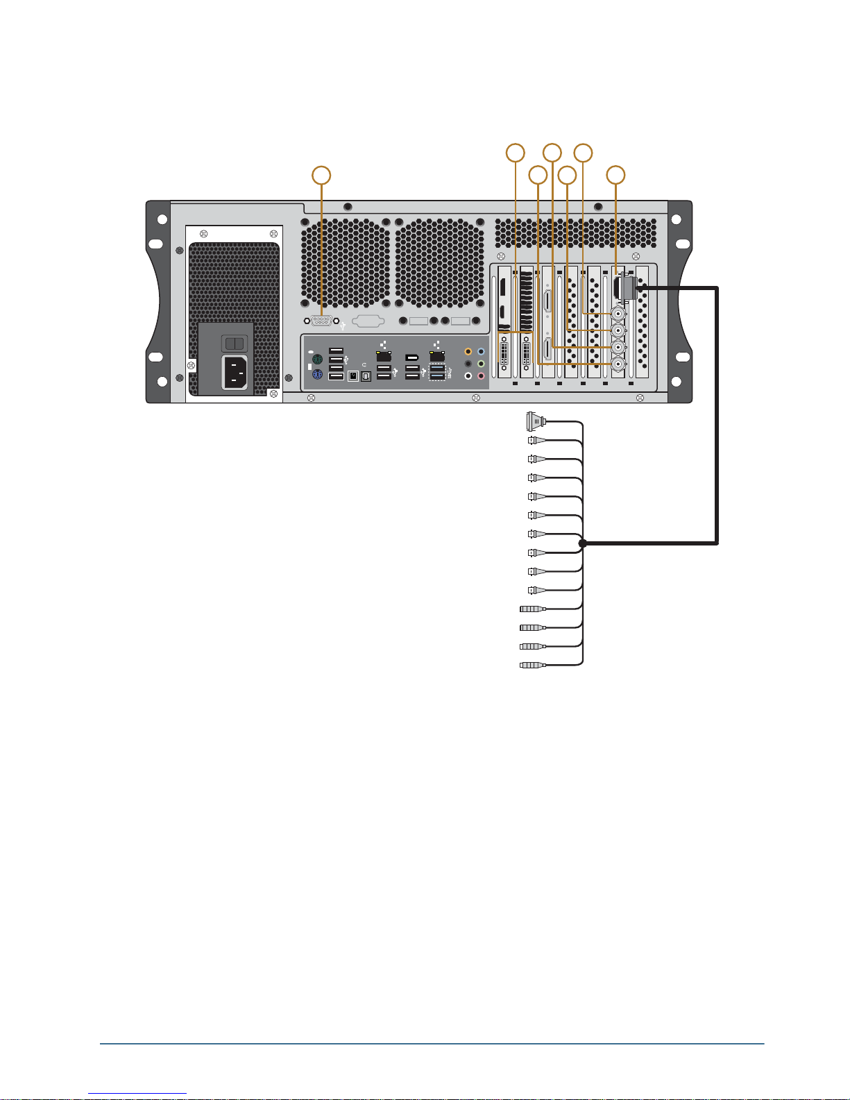
The following diagram (Figure 2.3) displays the Input/Output portion of the XPression Prime system. Descriptions
of individual components are contained in the legend below the diagram.
Figure 2.3 XPression Prime Rear Input/Output Connections
1. RS232 Port
Provides GPI and CII command functionality.
2. DVI Ports
Two DVI-I ports provide outputs for computer monitors. Digital monitors are recommended, however, analog
monitors are supported via VGA-DVI adapters.
3. SDI Input 2
Used for capturing a still image.
4. SDI Input 1
Provides background for when the XPression Prime system is using internal keying and also used for capturing a
still image.
5. SDI Key Out
Provides key or alpha channel output when in external key mode. Provides no output in internal key mod e.
XPression Prime Maintenance Guide (v01) Hardware Installation • 2–3
Page 14

6. SDI Fill Out
1394
USB3.0
CTR
BASS
REAR
SPK
SIDE
SPK
LINE
IN
FRONT
MIC IN
4
1
3
2
BIOS
USB BIOS Flashback
S/PDIF
Provides video fill in external key mode. In internal key mode, it provides the composite key over the input
background source.
7. Decklink St udio Breakout Port
Provides analog video output, audio, and reference input connections.
Rear Peripheral Connections
The following diagram (Figure 2.4) displays the peripheral connections under the Input/Output connections.
Descriptions of individual components are contained in the legend below the diagram.
Figure 2.4 Rear Peripheral Connections
1. PS/2 Ports
Use this port to connect peripheral devices such as a keyboard or mouse to the system.
2. GigE Ethernet Ports
Use this port to connect the XPression Prime system to an internal network. These ports can be used for
high-speed file transfer between the XPression Prime system and other computers on the internal network.
3. USB 2.0 Ports
Use these ports to connect peripheral devices such as a keyboard or mouse to the system. These ports can also be
used to transfer media to and from USB drives.
These ports support a maximum of 480 Mbit/s.
4. USB 3.0 Ports
Use these ports to connect peripheral devices such as a keyboard or mouse to the system. These ports can also be
used to transfer media to and from USB drives.
The ports support a maximum of 5 Gbit/s.
Use of USB 3.0 certified cable and devices are required for USB 3.0 super-speed data rates.
2–4 • Hardware Installation XPression Prime Maintenance Guide (v01)
Page 15

Power Supplies
The XPression Prime system has a single power supply, located at the rear of the system on the left-hand side.
The diagram (Figure 2.5) displays the parts of the power suppl y for the XPression Prime system. Descriptions of
individual components are contained in the legend below the diagram.
0
1
1
Figure 2.5 XPression Prime system Power Supply Unit
2
1. A/C Power Cord Connection
Connect the female end of the power cord to this connector, and the male end to a power circuit.
2. Power ON/OFF Switch
Turn the XPression Prime system power supply on or off.
Hardware Installation
The following sections provide installation instructions for the XPression Prime system hardware.
Unpacking the Unit
Unpack the XPression Prime system from the received shipping container(s), and check the contents against the
packing list to ensure all items are included. If any items are missing or damaged, contact your sales representative
or Ross Video for assistance.
Installation Requirements
Note the following installation requirements:
• Elevated Operating Ambient — If installed in a closed or multi-rack assembly, the operating ambient
temperature of the rack environment may be greater than the room ambient. Therefore, consideration should be
given to installing the equipment in an environment compatible with the maximum ambient temperature (Tma).
• Reduced Air Flow — Installation of the equipment in a rack or as a desktop/tower should be such that the
amount of air flow required for safe operation of the equipment in not compro mised.
• Mechanical Loading — Mounting of the equipment in the rack should be such that a hazardous condition is not
achieved due to uneven mechanical loading.
• Circuit Overloading — Consideration should be given to the connection of the equipment to the supply circuit
and the effect that overloading of the circuits might have on overcurrent protection and supply wiring.
Appropriate consideration of equipment nameplate rating should be used when addressing this concern.
• Reliable Earthing — Reliable earthing of rack and desktop/tower mounted equipment should be maintained.
Particular attention should be given to supply connections other than direct connections to the branch circuit (e.g.
use of power strips).
XPression Prime Maintenance Guide (v01) Hardware Installation • 2–5
Page 16

Installing the System in an Equipment Rack
The XPression Prime system can be rack mounted in a 16.9 inch wide equipment rack using a rack mount kit (not
supplied).
Contact Ross Video to order the rack mount kit for an XPression Prime system.
• Rack — 16.9 inch (43.0 cm) wide equipment rack
• Rack Units — 4 RU
• Height — 6.5 inches (17.6 cm)
• Depth — 21.5 inches, including rear BNCs (54.6 cm)
The slide rails must be installed onto the XPression Prime system before it can be mounted in an equipment rack.
Failure to install the XPression Prime system into an equipment rack using the rack mount kit available from
Ross Video will void the XPression Prime system warranty.
Installation Instructions
Note the following installation instructions:
1. This equipment has an operating temperature range of 0º C to 35º C. The ambient temperature in the rack shall
not exceed this temperature range.
2. A minimum clearance of 0.25” on each side of the equipment must be maintained after installation in the rack.
3. Take care not to compromise the stability of the rack by installing this equipment.
Setting Up the System as a Desktop
The XPression Prime system can be used as a desktop.
Installation Instructions
1. Place XPression Prime system horizontally on a level and stable surface.
Setting Up the System as a Tower
The XPression Prime system can be set up as a tower using the supplied pedestal feet.
Installation Instructions
1. Turn the four pedestal feet outwards to the sides of the XPression Prime system so that there are two deployed
pedestal feet on each side of the system.
2. Stand the XPression Prime system on a level and stable surface.
Attaching the Cables
T o attach the cables to the XPression Prime system:
1. On the back of the XPression Prime system, connect the supplied line cords to the power supply, then plug the
line cord into a grounded outlet.
The power supply is auto-sensing and can accept line voltages from 100 through 240VAC.
2. Plug the supplied USB keyboard into the upper USB port on the back of the XPression Prime system.
3. Plug the supplied USB mouse into the lower USB port.
4. Connect a monitor, customer supplied, to the DVI 1 port.
An additional monitor can be connected to the DVI 2 port to provide additional space for virtual preview
channels, custom applications, web page capture, and more.
5. Plug an Ethernet cable from the internal network into one of the GigE Ethernet ports.
XPression Prime systems can run standalone or accept a network connection if required to connect to a
production network. XPression Prime systems also use this TCP/IP network connection to support the Smart
GPI Feature.
2–6 • Hardware Installation XPression Prime Maintenance Guide (v01)
Page 17

6. Connect the GenLock signal cable to the REF IN BNC connector on the breakout cable. This connection is
required to lock the XPression Prime system to the video timing of the facility. The XPression Prime system
supports the following types of GenLock signal:
• Analog BlackBurst — a composite color video signal comprised of sync, color burst, and black video. Also
called “color black”, “house sync” or “house black”. Typically used as the house reference synchronization
signal.
• Tri-Level Sync — a three-level pulse synchronizatio n si gnal used in high definition systems.
T o transmit the GenLock signal from the XPression Prime system, connect a GenLock signal cable to the REF
OUT BNC connector.
7. On the breakout cable, connect the audio output cables to the AES/EBU BNCs. After the XPression Prime
system is up and running, audio outputs can be assigned to each video channel.
The XPression Prime system provides AES3id 75 ohm BNC outputs. If AES3 110 ohm connections are
required, optional GearLite adaptors are available from Ross Video. For facilities requiring analog outputs,
additional outboard analog to digital conversion equipment is also available from Ross Video.
8. Connect your Video Input cables to the VIDEO IN BNC connectors.
The XPression Prime system provides either SDI or SDI / HD-SDI inputs. For facilities requiring analog
inputs, additional outboard analog to digital conversion equipment is also available from Ross Video.
9. Connect Channel 1 Fill & Key output cables from SDI Fill Out and SDI Key Out outputs to their required
destination (production switcher, master control switcher, or keyer for example).
The XPression Prime system provides either SDI or SDI / HD-SDI outputs. For facilities requiring analog
outputs, additional outboard analog to digital conversion equipment is also available from Ross Video.
Powering Up the System
T o power up the system:
1. Press the Power button to begin the boot procedure.
If the system does not boot, ensure that the power ON/OFF switch on the power supply is turned on.
2. Close the front door to protect the XPression Prime system from dust.
Powering Down the System
Whenever the XPression Prime system needs to be powered down, use the following procedure:
To power down the system:
1. Log on to the XPression Prime system using the following user name with no password:
• User name: xpression
2. From the Start Menu, select Shut Down.
The Shut Down Windows dialog box opens.
3. Select Shut down from the list.
4. Click OK.
XPression Prime Maintenance Guide (v01) Hardware Installation • 2–7
Page 18

2–8 • Hardware Installation XPression Prime Maintenance Guide (v01)
Page 19

Maintenance
This chapter provides information on maintaining the XPression Prime system.
Caution — Danger of Explosion if the system lithium battery is incorrectly replaced. Replace only with
the same or equivalent type of battery recommended by the manufacturer. Dispose of used batteries
according to the manufacturer’s instructions by a qualified service person.
Front Door Filter Maintenance
The front door on the XPression Prime system comes equipped with two mesh filters to protect the inside of the
XPression system from dust and debris.
Ross Video recommends that the following filter maintenance be performed:
• Periodically check the filter for dust and debris buildup and clean the filter.
• Replace the filter if it is damaged or worn.
Cleaning the Front Door Filters
The mesh filter can be cleaned with a soft brush, cloth, or vacuum as needed. If the filter requires a more thorough
cleaning, it can be removed from the door and washed with a mild soap and water solution.
The filter must be completely dry before it is reinstalled in the door.
Removing the Front Door Filters
To remove the filters from the front door of the XPression Pr ime system:
1. Open the front door of the XPression Prime system.
XPression Prime Maintenance Guide (v01) Maintenance • 3–1
Page 20

2. Lift the filters from the door.
The filters can now be thoroughly cleaned.
Re-installing the Front Door Filters
To re-install the filters in the front door of the XPression Prime system:
3. Insert the filters into the inside of the open front door.
4. Snap the nubs on the sides of the filters into the grooves on the inside of the front door.
3–2 • Maintenance XPression Prime Maintenance Guide (v01)
Page 21

Removing the Front Fan Filter
T o remove the filter from the front fan of the XPression Prime system:
1. Open the front door of the XPression Prime system.
2. Unscrew the two thumb screws on the front fan cage.
3. Remove the front fan cage from the XPression Prime system.
XPression Prime Maintenance Guide (v01) Maintenance • 3–3
Page 22

4. Remove the filter from the front fan cage.
Re-installing the Front Fan Filter
To re-install the filter from the front fan of the XPression Prime system:
1. Insert the filter into the front fan cage.
2. Insert the front fan cage into the front of the XPression Prime system.
3–4 • Maintenance XPression Prime Maintenance Guide (v01)
Page 23

3. Tighten the two thumb screws to fasten the front fan cage to the XPression Prime system.
4. Close the front door of the XPression Prime system.
Replacing a System Drive
The XPression Prime system drives that are located inside the chassis can be replaced.
XPression Prime drives are not hot-swappable. The system m ust be shut down before replacing a drive.
Protective Earth — Static discharge can cause serious damage to sensitive devices. Avoid handling
any hard drive in high static environments such as carpeted areas and when synthetic fiber clothing is
worn. Touch the chassis to dissipate static charge before removing hard drives from th e system, and
exercise proper grounding precautions when working around the XPression system.
Removing a System Drive
T o remove a system drive from the XPression Prime system:
1. Make sure the XPression Prime system is shut down.
2. Remove the top panel from the XPression Prime system. Refer to the section “Removing and Re-Installing
the Top Panel” on page 3–9 for instructions.
3. Disconnect the power wires from the drives.
XPression Prime Maintenance Guide (v01) Maintenance • 3–5
Page 24

4. Disconnect the XPression Prime system from the drives.
5. Using a Phillips head screwdriver, remove the two screws located on the top of the drive cage at the front of the
XPression Prime system.
Do not remove the black screws and grommets located on the drive cage.
6. Gently lift the drive cage from the XPression Prime system.
3–6 • Maintenance XPression Prime Maintenance Guide (v01)
Page 25

7. Using a Phillips head screwdriver, remove the screws from the drive cage. There are four screws in total per
drive.
8. Remove the drive from the drive cage.
Replacing a System Drive
To replace a system drive:
1. Insert the new drive into the drive cage with the with label facing upwards and the connectors at the open end
of the cage.
XPression Prime Maintenance Guide (v01) Maintenance • 3–7
Page 26

2. Insert and tighten the Phillips head screws in the screw holes. There are four screws in total: two on each side
of the drive cage.
The drive cage is now ready to be re-inserted into the XPression Prime system.
3. Insert the drive cage into the XPression Prime system.
4. Using a Phillips head screwdriver, insert the two screws on the top of the drive cage at the front of the
XPression Prime system.
3–8 • Maintenance XPression Prime Maintenance Guide (v01)
Page 27

5. Connect the XPression Prime system to the drives.
6. Connect the power wires to the drives.
7. Re-install the top panel on the XPression Prime system. Refer to the section “Removing and Re-Installing the
Top Panel” on page 3–9 for instructions.
Removing and Re-Installing the Top Panel
The top panel of the XPression Prime system can be removed to gain access to internal components such as fans,
cards, and the USB security dongle.
Caution — Do not operate the XPression system with the top panel removed.
To remove the top panel of the XPression Prime system:
1. Shutdown the XPression Prime system, remove all cabling, and place the system on a flat, non-slip surface.
XPression Prime Maintenance Guide (v01) Maintenance • 3–9
Page 28

2. Remove the two thumbscrews at the back of the XPression system.
Set the two thumbscrews aside, as they will be needed to replace the top panel.
3. Gently pull the top panel back towards the rear of the unit, creating a gap between the top panels of the unit.
4. Lift the top panel off the chassis.
3–10 • Maintenance XPression Prime Maintenance Guide (v01)
Page 29

T o re-inst all the top panel
1. Place the top panel onto the top of the XPression Prime system as follows:
• Face the sides of the top panel down around the sides of the system.
• Line up the four nubs on the inside of the sides of the top panel with the L-shaped grooves on the sides of the
system.
2. Gently slide the top panel into place, until a clicking noise is heard and the top panel is flush to the front top of
the XPression Prime system.
3. Insert and tighten the two thumbscrews into the back of the XPression system.
XPression Prime Maintenance Guide (v01) Maintenance • 3–11
Page 30

Replacing Cooling Fans
The XPression Prime system has three cooling fans. The front chassis fan can be replaced if it fails.
There are two fans on the CPU cooler. To replace the CPU cooler fans, please contact Ross Video Technical
Support for assistance.
The XPression system must be shut down wh en replacing the cooling fans.
Protective Earth — Static discharge can cause serious damage to sensitive devices. Avoid handling
any hard drive in high static environments such as carpeted areas and when synthetic fiber clothing is
worn. Touch the chassis to dissipate static charge before removing hard drives from th e system, and
exercise proper grounding precautions when working around the XPression system.
If a fan fails, the fan failure alarm will trigger. Refer to the section “Power LED Area” on page 2–1 for further
information on XPression Prime system hardware alarms.
Replacing the front chassis fan
T o remove the front chassis fan:
1. Make sure the XPression Prime system is shut down.
2. Remove the top panel from the XPression Prime system. Refer to the section “Removing and Re-Installing
the Top Panel” on page 3–9 for instructions.
3. Disconnect the front chassis fan power supply wire.
4. Open the front door of the XPression Prime system.
3–12 • Maintenance XPression Prime Maintenance Guide (v01)
Page 31

5. Unscrew the two thumb screws on the front fan cage.
6. Remove the front fan cage from the XPression Prime system.
7. Using a Phillips head screwdriver, remove the screws from the from the fan cage. There are four screws in
total.
XPression Prime Maintenance Guide (v01) Maintenance • 3–13
Page 32

8. Remove the fan from the fan cage.
To install the front chassis fan:
1. Insert the new fan into the fan cage.
2. Insert and tighten the Phillips head screws in the screw holes. There are four screws in total.
3–14 • Maintenance XPression Prime Maintenance Guide (v01)
Page 33

3. Insert the front fan cage in the XPression Prime system with the fan wire inside the XPression Prime chassis.
4. Tighten the two thumb screws on the front fan cage.
5. Close the front door of the XPression Prime system.
XPression Prime Maintenance Guide (v01) Maintenance • 3–15
Page 34

6. Connect the front chassis fan power supply wire.
7. Replace the top panel. Refer to the section “Removing and Re-Installing the Top Panel” on page 3–9 for
instructions.
Accessing the USB Security Dongle
You may be required to remove or replace the USB security dongle if instructed to do so by Ross Video Technical
Support.
To access the USB security dongle:
1. Remove the top panel from the XPression Prime system. Refer to the section “Removing and Re-Installing
the Top Panel” on page 3–9 for instructions.
2. The USB security dongle is located inside the chassis behind the front chassis fan. The security dongle
connects to the XPression Prime system via a USB interface. Remove and replace the security dongle as
instructed by Ross Video Technical Support.
Use the additional USB interface to install an additional dongle if necessary.
3. Replace the top panel. Refer to the section “Removing and Re-Installing the Top Panel” on page 3–9 for
instructions.
3–16 • Maintenance XPression Prime Maintenance Guide (v01)
Page 35

Replacing the Power Supply
The XPression Prime system has one power supply, located at the rear of the system on the left-hand side.
Protective Earth — Static discharge can cause serious damage to sensitive devices. Touch the
chassis to dissipate static charge before removing power supplies from the system, and exercise proper
grounding precautions when working around the XPression system.
Keep the following safety information in mind while removing the power supply from the XPression Prime system:
• Always ground yourself before touching electronic equipment.
• When removing the power supply unit, always support the unit with two hands to help prevent dropping it.
Warning Hazardous Voltages — Disconnect the power supply from AC mains before servicing.
Hazardous voltages remain within the power supply for a short period of time after removal from the
system. The power supply cover is intended to protect the user from access to these areas, and should
not be removed. Ross Video power supplies are intended to be factory serviced by qualified Ross Video
service personnel only. Service or any component replacement is not advised.
Removing the Power Supply
To remove the power supply from the XPression Prime system:
1. Make sure the XPression Prime system is shut down.
2. At the back of the XPression Prime system, turn off the power switch located on the power supply.
3. Disconnect the power cord from the power supply.
4. Remove the top panel from the XPression Prime system. Refer to the section “Removing and Re-Installing
the Top Panel” on page 3–9 for instructions.
5. Unscrew the retaining bar screw.
XPression Prime Maintenance Guide (v01) Maintenance • 3–17
Page 36

6. Remove the retaining bar.
7. Disconnect the power supply cables from the XPression Prime system. There are six cables in total to
disconnect:
• two from the motherboard (1, 3)
• one from the GPU (2)
• two from the system drives (4, 5)
• one from the DVD drive (6)
1
3
2
4
6
5
3–18 • Maintenance XPression Prime Maintenance Guide (v01)
Page 37

8. Unscrew the four screws that fasten the power supply to the XPression Prime chassis.
9. Gently remove the power supply from the XPression Prime chassis.
Installing a Power Supply
To install a new power supply in the XPression Prime system:
1. Gently insert the power supply in the XPression Prime chassis.
XPression Prime Maintenance Guide (v01) Maintenance • 3–19
Page 38

2. Insert and tighten the four screws to fasten the power supply to the XPression Prime chassis.
3. Connect the power supply cables to the XPression Prime system. There are six cables in total to connect:
• two from the motherboard (1, 3)
• one from the GPU (2)
• two from the system drives (4, 5)
• one from the DVD drive (6)
1
4. Attach the retaining bar.
6
3
5
2
4
3–20 • Maintenance XPression Prime Maintenance Guide (v01)
Page 39

5. Insert and tighten the retaining bar screw.
6. Re-install the top panel on the XPression Prime system. Refer to the section “Removing and Re-Installing the
Top Panel” on page 3–9 for instructions.
7. Connect the power cord to the power supply.
8. At the back of the XPression Prime system, turn on the power switch located on the power supply.
XPression Prime Maintenance Guide (v01) Maintenance • 3–21
Page 40

3–22 • Maintenance XPression Prime Maintenance Guide (v01)
Page 41

Appendix A: Pinouts
This appendix provides information on the RS232 port pinouts.
RS232
XPression offers two GPI options:
• GPI 1: Data Set Ready pin 6 and pin 7
• GPI 2: Clear to Send pin 8 and pin 7
The RS232 port can also be used for CII using the XPression CII Gateway option.
54321
9876
Figure A.1 RS232 — Male
Table A.1 RS232 Pinouts
Pin # Signal Pin Signal
1 Data Carrier Detect
6 Data Set Ready
2 Received Data
3 Transmitted Data
4 Data Terminal Ready
5 Signal Ground
7 Request to Send
8 Clear to Send
9 Ring Indicator
When creating an RS232 GPI trigger, create a device that short-circuits either pin 8-7 or 6-7 on the nine pin
female connector. No additional power can be added to the circuit or it will damage the RS232 port.
XPression Prime Maintenance Guide (v01) Appendix A: Pinouts • A–1
Page 42

A–2 • Appendix A: Pinouts XPression Prime Maintenance Guide (v01)
 Loading...