

Page 1

Operator’s Manual
Software Issue: 7.2 MD-S100
Ross Video Limited
Page 2

Synergy 100 MD • Operator’s Manual
• Ross Part Number: 4400DR-103
• Document Issue: 7
• Release Date: August 30, 2007. Printed in Canada.
• Software Issue: 7.2 MD-S100
The information contained in this Operator’s Manual is subject to change without notice or obligation.
Copyright
© 2007 Ross Video Limited. All rights reserved.
Contents of this publication may not be reproduced in any form without the written permission of
Ross Video Limited. Reproduction or reverse engineering of copyrighted software is prohibited.
Notice
The material in this manual is furnished for informational use only. It is subject to change without
notice and should not be construed as commitment by Ross Video Limited. Ross Video Limited
assumes no responsibility or liability for errors or inaccuracies that may appear in this manual.
Trademarks
• is a registered trademark of Ross Video Limited.
• Ross, ROSS, ROSS
• All other product names and any registered and unregistered trademarks mentioned in
this guide are used for identification purposes only and remain the exclusive property of
their respective owners.
®
, and MLE are registered trademarks of Ross Video Limited.
Page 3

Important Regulatory and Safety Notices to Service Personnel
Before using this product and any associated equipment, refer to the “Important Safety
Instructions” listed below to avoid personnel injury and to prevent product damage.
Product may require specific equipment, and/or installation procedures to be carried out to satisfy
certain regulatory compliance requirements. Notices have been included in this publication to call
attention to these specific requirements.
Symbol Meanings
Protective Earth
Warning
Caution
Notice
Warning Hazardous
Voltages
ESD Susceptibility
This symbol identifies a Protective Earth (PE) terminal, which is
provided for connection of the supply system’s protective earth (green
or green/yellow) conductor.
This symbol on the equipment refers you to important operating and
maintenance (servicing) instructions within the Product Manual
Documentation. Failure to heed this information may present a major
risk of damage or injury to persons or equipment.
The symbol with the word “Warning” within the equipment manual
indicates a potentially hazardous situation which, if not avoided, could
result in death or serious injury.
The symbol with the word “Caution” within the equipment manual
indicates a potentially hazardous situation which, if not avoided, may
result in minor or moderate injury. It may also be used to alert against
unsafe practices.
The symbol with the word “Notice” within the equipment manual
indicates a situation which, if not avoided, may result in major or
minor equipment damage or a situation which could place the
equipment in a non-compliant operating state.
This symbol is intended to alert the user to the presence of uninsulated
“dangerous voltage” within the product enclosure that may be of
sufficient magnitude to constitute a risk of shock to persons.
This symbol is used to alert the user that an electrical or electronic
device or assembly is susceptible to damage from an ESD event.
Important Safety Instructions
Warning
1) Read these instructions.
2) Keep these instructions.
3) Heed all warnings.
4) Follow all instructions.
5) Do not use this apparatus near water.
6) Clean only with a dry cloth.
7) Do not block any ventilation openings. Install in accordance with manufacturer’s instructions.
Page 4

Warning
8) Do not install near heat sources such as radiators, heat registers, stoves, or other apparatus
(including amplifiers) that produce heat.
9) Do not defeat the safety purpose of the polarized or grounding-type plug. A polarized plug has two
blades with one wider than the other. A grounding type plug has two blades and a third grounding
prong. The third prong is provided for your safety. If the provided plug does not fit into your outlet,
consult an electrician for replacement of the obsolete outlet.
10) Protect the power cord from being walked on or pinched, particularly at plugs, convenience
receptacles, and the point where they exit from the apparatus.
11) Only use attachments/accessories specified by the manufacturer.
12) Unplug this apparatus during lightning storms or when unused for long periods of time.
13) Refer all servicing to qualified service personnel. Servicing is required when the apparatus has
been damaged in any way, such as power-supply cord or plug is damaged, liquid has been spilled or
objects having fallen into the apparatus, the apparatus has been exposed to rain or moisture, does not
operate normally, or has been dropped.
14) Do not expose this apparatus to dripping or splashing, and ensure that no objects filled with
liquids, such as vases, are placed on the apparatus.
15) To completely disconnect this apparatus from the AC Mains, disconnect the power supply cord
plug from the AC receptacle.
16) The mains plug of the power supply cord shall remain readily operable.
17) The MD or MD-X (Live Production Engine) chassis is to be rack mounted only.
18) Indoor Use: WA R NI N G : To reduce the risk of fire or electric shock, do not expose this
apparatus to rain or moisture.
Caution
19) The safe operation of this product requires that a protective earth connection be provided. A
grounding conductor in the equipment's supply cord provides this protective earth. To reduce the risk
of electrical shock to the operator and service personnel, this ground conductor must be connected to
an earthed ground.
20) WARNING: This apparatus, when equipped with multiple power supplies, can generate high
leakage currents. To reduce the risk of electric shock, ensure that each individual supply cord is
connected to its own separate branch circuit with an earth connection.
21) CAUTION: These service instructions are for use by qualified service personnel only. To reduce
the risk of electric shock, do not perform any servicing other than that contained in the operating
instructions unless you are qualified to do so (Engineering Manual only).
22) This apparatus contains Lithium batteries, which if replaced incorrectly, or with an incorrect
type, may cause an explosion. Replace only with the same type. Dispose of used batteries
according to the manufacturer’s instruction.
23) Service barriers within this product are intended to protect the operator and service personnel from
hazardous voltages. For continued safety, replace all barriers after servicing.
24) Certain parts of this equipment still present a safety hazard with the power switch in the OFF
position. To avoid electrical shock, disconnect all A/C power cords from the chassis' rear appliance
connectors before servicing.
25) This product contains safety critical parts, which, if incorrectly replaced, may present a risk of fire
or electrical shock. Components contained within the product’s power supplies and power supply area
are not intended to be customer-serviced and should be returned to the factory for repair.
26) To reduce the risk of fire, replacement fuses must be the same type and rating.
Page 5

27) Use only power cords specified for this product and certified for the country of use. Refer to the
Product Power Cord Requirement section that follows.
28) The safe operation of this equipment requires that the user heed and adhere to all installation and
servicing instruction contained within the equipment’s Engineering Manuals.
Product Power Cord Requirements
Caution
North American Line Voltages 100 - 120 Volt
This product is supplied with certified 10A/125V SVT type supply cords. Conductors are color coded
white (neutral), black (line), and green or green/yellow (ground).
Operation of this equipment at line voltages exceeding 130V requires that alternative supply cords
with appropriate voltage and current ratings be used.
International Line Voltages 200 - 240 Volts
This product has been designed for use with certified IEC 320- C13 10A/250V - H03 VV-F3G
1.00mm
International product orders are supplied with a certified 10A/250V line cords, utilizing a molded
3-pin IEC 320-C13 type connector at one end and stripped conductors on the other. One line cord is
provided. Conductors are CEE color coded; blue (neutral), brown (line), and green/yellow (ground).
Installation by a qualified electrician, of an appropriately approved A/C wall plug certified for the
country of use, is required.
Alternatively, other IEC 320 C-13 type power cords may be used, provided that they meet the
necessary safety certification requirements for the country in which they are to be used. Refer to the
correctly specified line cord above.
2
type line cord.
EMC Notices
United States of America
FCC Part 15
This equipment has been tested and found to comply with the limits for a class A Digital device,
pursuant to part 15 of the FCC Rules. These limits are designed to provide reasonable protection
against harmful interference when the equipment is operated in a commercial environment. This
equipment generates, uses, and can radiate radio frequency energy and, if not installed and used in
accordance with the instruction manual, may cause harmful interference to radio communications.
Operation of this equipment in a residential area is likely to cause harmful interference in which case
the user will be required to correct the interference at his own expense.
Notice
Changes or modifications to this equipment not expressly approved by
Ross Video Limited could void the user’s authority to operate this
equipment.
CANADA
This Class “A” digital apparatus complies with Canadian ICES-003.
Cet appariel numerique de la classe “A” est conforme a la norme NMB-003 du Canada.
Page 6

EUROPE
This equipment is in compliance with the essential requirements and other relevant provisions of CE
Directive 93/68/EEC.
INTERNATIONAL
This equipment has been tested to CISPR 22:1997 along with amendments A1:2000 and A2:2002,
and found to comply with the limits for a Class A Digital device.
Notice
This is a Class A product. In domestic environments, this product may
cause radio interference, in which case the user may have to take
adequate measures.
General Handling Guidelines
• Careful handling, using proper ESD precautions, must be observed.
• Power down the system before PCB removal.
A Word About Static Discharge
Throughout the many procedures in this Operator’s Manual, please observe all static discharge
precautions.
Notice
Avoid handling the switcher circuit boards in high static environments
such as carpeted areas, and when synthetic fiber clothing is worn.
Touch the frame to dissipate static charge before removing boards
from the frame, and exercise proper grounding precautions when
working on circuit boards.
Page 7

Warranty and Repair Policy
Ross Video Limited (Ross) warrants its switchers and related options, to be free from defects under
normal use and service for a period of THREE YEARS from the date of shipment. Fader handle
assemblies are warranted for the life of the product. If an item becomes defective within the warranty
period Ross will repair or replace the defective item, as determined solely by Ross.
Warranty repairs will be conducted at Ross, with all shipping FOB Ross dock. If repairs are conducted
at the customer site, reasonable out-of-pocket charges will apply. At the discretion of Ross, and on a
temporary loan basis, plug in circuit boards or other replacement parts may be supplied free of charge
while defective items undergo repair. Return packing, shipping, and special handling costs are the
responsibility of the customer.
Software upgrades for switchers, as defined by Ross, may occur from time to time. Ross will notify
customers of such upgrades and, subject to a customer-initiated request, such upgrades will be
provided free of charge within three years of the original ship date, with shipping FOB Ross dock.
This warranty is void if products are subjected to misuse, neglect, accident, improper installation or
application, or unauthorized modification.
In no event shall Ross Video Limited be liable for direct, indirect, special, incidental, or consequential
damages (including loss of profit). Implied warranties, including that of merchantability and fitness
for a particular purpose, are expressly limited to the duration of this warranty.
This warranty is TRANSFERABLE to subsequent owners, subject to Ross’ notification of change of
ownership.
Page 8

Environmental Information
The equipment that you purchased required the extraction and use of natural
resources for its production. It may contain hazardous substances that could impact
health and the environment.
To avoid the potential release of those substances into the environment and to diminish the need for
the extraction of natural resources, Ross Video encourages you to use the appropriate take-back
systems. These systems will reuse or recycle most of the materials from your end-of-life equipment in
an environmentally friendly and health conscious manner.
The crossed-out wheeled bin symbol invites you to use these systems.
If you need more information on the collection, reuse, and recycling systems, please contact your
local or regional waste administration.
You can also contact Ross Video for more information on the environmental performances of our
products.
Page 9

Company Address
Ross Video Limited
8 John Street
Iroquois, Ontario, K0E 1K0
Canada
General Business Office:
Technical Support:
After hours emergency:
E-mail (Technical Support):
E-mail (General Information):
Web si te :
Fax:
Ross Video Incorporated
P.O. Box 880
Ogdensburg, New York
USA 13669-0880
(+1) 613 • 652 • 4886
(+1) 613 • 652 • 4425
(+1) 613 • 652 • 4886
(+1) 613 • 349 • 0006
techsupport@rossvideo.com
solutions@rossvideo.com
http://www.rossvideo.com
Page 10

Page 11

Contents
Introduction 1
A Word of Thanks ................................................................................................................1-1
About This Manual ..............................................................................................................1-2
Documentation Conventions ................................................................................................1-4
Documentation Terms ..........................................................................................................1-5
Abbreviations .......................................................................................................................1-6
Related Publications ............................................................................................................1-7
Product Overview ................................................................................................................1-8
Product Highlights ................................................................................................1-8
Standard Features ................................................................................................1-10
System Options ....................................................................................................1-16
A Word about Technical Support .......................................................................................1-21
Product Comparison Charts ...............................................................................................1-22
Control Panel Introduction 2
In This Chapter ....................................................................................................................2-1
Control Panel Sections .........................................................................................................2-2
Video Flow through the Switcher ........................................................................................2-5
Switcher Timeout .................................................................................................................2-6
Resetting the Switcher .........................................................................................................2-7
Shutting Down the Switcher ................................................................................................2-8
Restarting the Switcher ........................................................................................................2-9
Using the Menu System 3
In This Chapter ....................................................................................................................3-1
Menu System Basics ............................................................................................................3-2
Menu Information ..................................................................................................3-3
Menu System Operation ......................................................................................................3-7
Help Features .....................................................................................................................3-11
Help Menu ...........................................................................................................3-11
Switcher Basics 4
In This Chapter ....................................................................................................................4-1
Switcher Personality ............................................................................................................4-2
Transition Preview .................................................................................................4-2
DSK Drop ..............................................................................................................4-3
Sleep Time .............................................................................................................4-3
Menu Button Operation .........................................................................................4-4
Auto Recall ............................................................................................................4-5
Global-Store Memory Recall ................................................................................4-6
Isolate MultiDSK ..................................................................................................4-7
Basic Switcher Functions .....................................................................................................4-8
Buttons ...................................................................................................................4-8
Reverse SHIFT Mode ...........................................................................................4-9
Flip Flop Operations ..............................................................................................4-9
Key Bus ...............................................................................................................4-10
Synergy 100 MD Operator’s Manual (v7.2 MD-S100) Contents • i
Page 12

On-Air Indicators ................................................................................................ 4-11
Knobs .................................................................................................................. 4-12
Fade to Black ..................................................................................................................... 4-13
Performing a Fade to Black ................................................................................ 4-13
Resetting the Switcher ....................................................................................................... 4-15
Software Reset .................................................................................................... 4-15
Full Restart .......................................................................................................... 4-16
Shutting Down the Switcher ............................................................................................. 4-17
Transitions 5
In This Chapter .................................................................................................................... 5-1
Transition Control Group .................................................................................................... 5-2
Transition Control Group Overview ..................................................................... 5-2
Working with Next Transitions ........................................................................................... 5-5
Example Transitions ............................................................................................. 5-5
Performing Transitions ........................................................................................................ 5-8
Eight Steps to a Flawless Transition ..................................................................... 5-8
Performing Auto Transitions ................................................................................ 5-8
Performing Manual Transitions .......................................................................... 5-10
Performing Cuts .................................................................................................. 5-10
Performing Dissolves .......................................................................................... 5-11
Performing a Transition Limit Effect ................................................................. 5-12
Performing a Transition Preview ........................................................................ 5-13
Performing a Preset Black Transition ................................................................. 5-14
Pattern and Effects Control 6
In This Chapter .................................................................................................................... 6-1
Effects Control Groups ........................................................................................................ 6-2
Effects Control Modes .......................................................................................... 6-2
Wipes ................................................................................................................................... 6-4
Using Wipes ........................................................................................................................ 6-6
Selecting Wipes .................................................................................................... 6-7
Mattes Group ..................................................................................................................... 6-10
Keying 7
In This Chapter .................................................................................................................... 7-1
Introduction to Keying ........................................................................................................ 7-2
Key Group Basics ................................................................................................. 7-2
Effects Keyers Group ............................................................................................ 7-2
Downstream Keyer Group .................................................................................... 7-5
A Word About FlexiClean .................................................................................... 7-8
Using Keys .......................................................................................................................... 7-9
Performing a Self Key .......................................................................................... 7-9
Performing an Auto Select Key .......................................................................... 7-10
Performing a Preset Pattern Key ......................................................................... 7-11
UltraChrome Chroma Keys ............................................................................................... 7-13
Choosing an UltraChrome Operating Mode ....................................................... 7-13
Performing an UltraChrome Chroma Key in Basic Mode ................................. 7-14
Performing an UltraChrome Chroma Key in Advanced Mode .......................... 7-19
Chroma Key Lighting Tips ................................................................................. 7-30
ii • Contents Synergy 100 MD Operator’s Manual (v7.2 MD-S100)
Page 13

Split Keys ...........................................................................................................................7-33
Performing a Split Key ........................................................................................7-33
Performing a Split Video .....................................................................................7-34
MultiDSK Option ..............................................................................................................7-35
MultiDSK Operation ...........................................................................................7-35
Setting MultiDSK Sources and Transition Rates ................................................7-35
DSK Drop ............................................................................................................7-37
Isolate MultiDSK ................................................................................................7-38
MultiDSK Control Using a GPI ..........................................................................7-38
Programming a Favorite CG ..............................................................................................7-40
Using Auto Transitions With Keys ....................................................................................7-41
Key Auto Transition Notes ..................................................................................7-41
Key Modifiers 8
In This Chapter ....................................................................................................................8-1
Filling a Key with Matte ......................................................................................................8-2
Masking Keys ......................................................................................................................8-3
Inverting Keys ......................................................................................................................8-4
Flying Keys ..........................................................................................................................8-5
Positioner .............................................................................................................................8-6
Memory and Disk Functions 9
In This Chapter ....................................................................................................................9-1
Memory Functions ...............................................................................................................9-2
Storing Memory Registers .....................................................................................9-3
Recalling Memory Registers .................................................................................9-5
Effects Dissolve ...................................................................................................................9-8
Notes on Using Effects Dissolve ...........................................................................9-8
Creating a Basic Effects Dissolve .........................................................................9-9
Working with Channels and Objects ...................................................................9-10
Using Storage Devices .......................................................................................................9-12
Disk Menu Tree ...................................................................................................9-12
Saving Registers ..................................................................................................9-13
Recalling Registers ..............................................................................................9-15
Notes on Using a USB Drive ...............................................................................9-16
Peripheral Control and More 10
In This Chapter ..................................................................................................................10-1
GPI Control ........................................................................................................................10-2
Using the Aux Bus .............................................................................................................10-3
Remote Aux Panels ............................................................................................................10-5
Using an Assignable Remote Aux Panel .............................................................10-5
Operating a Remote Aux Panel ...........................................................................10-6
Preview Overlay ................................................................................................................10-7
Center Overlay .....................................................................................................10-7
Safe Title Overlay ................................................................................................10-8
Editor Interface ..................................................................................................................10-9
Copy and Swap Functions ...............................................................................................10-10
Copy Key ...........................................................................................................10-10
Key Swap ..........................................................................................................10-11
Synergy 100 MD Operator’s Manual (v7.2 MD-S100) Contents • iii
Page 14

Global-Store 11
In This Chapter .................................................................................................................. 11-1
Preparing for Image Transfers ........................................................................................... 11-2
Image Specifications ........................................................................................... 11-2
File Naming Conventions ................................................................................... 11-3
Creating a Connection to Your Switcher ........................................................................... 11-5
Alternate Connection Method ............................................................................. 11-6
Transferring Still Images and Animations ........................................................................ 11-7
Copying Still Images and Animations to your Switcher .................................... 11-7
Copying Images and Animations from your Switcher ....................................... 11-8
Legacy Image and Animation Files .................................................................... 11-8
Global-Store ...................................................................................................................... 11-9
Global-Store Menu Tree ..................................................................................... 11-9
Selecting a Still for a Global-Store Channel ..................................................... 11-10
Renaming a Still .................................................................................................11-11
Cancelling a Still from a Global-Store Channel ............................................... 11-12
Managing Stills and Directories ....................................................................... 11-13
On Air Properties .............................................................................................. 11-17
Default Stills ..................................................................................................... 11-23
Capturing Stills ................................................................................................. 11-25
Restarting the Global-Store .............................................................................. 11-26
Squeeze & Tease MD Basic Operation 12
In This Chapter .................................................................................................................. 12-1
Operational Overview ....................................................................................................... 12-2
Working in 3D Space ........................................................................................................ 12-3
Channel Location in 3D Space ........................................................................... 12-3
Position Coordinates ........................................................................................... 12-3
Screen and Channel Location ............................................................................. 12-4
Perspective .......................................................................................................... 12-5
Channel Rotation ................................................................................................ 12-7
Channel Centering .............................................................................................. 12-8
Control Options .................................................................................................. 12-8
Conclusion .......................................................................................................... 12-9
Using the Positioner ........................................................................................................ 12-10
Using the Mattes Color Knobs ........................................................................................ 12-11
Squeeze & Tease Menu System ...................................................................................... 12-12
Through the Main Menu ................................................................................... 12-12
Hide Menus ....................................................................................................... 12-12
Squeeze & Tease MD Menu Tree ................................................................................... 12-15
3D Guidelines .................................................................................................................. 12-16
Fly Key Rules ................................................................................................... 12-16
Using Two Channels in Different Keys ............................................................ 12-17
Channel Listing ............................................................................................................... 12-18
Channel Status .................................................................................................. 12-18
Channels ........................................................................................................... 12-19
Active Keyer ..................................................................................................... 12-19
Working with Channels ................................................................................................... 12-20
Assigning Multiple Channels to a Flying Key ................................................. 12-20
Channel Management ...................................................................................................... 12-21
Navigating to the Channel Management Menu ................................................ 12-21
Channel Selection ............................................................................................. 12-21
iv • Contents Synergy 100 MD Operator’s Manual (v7.2 MD-S100)
Page 15

Channel Layering and Intersect .......................................................................................12-23
Frontside/Backside Video ................................................................................................12-24
Activating Backside Video ................................................................................12-24
Selecting Crosspoints for Frontside/Backside Video ........................................12-24
Auto Flip ............................................................................................................12-25
Using Frontside/Backside Video with Sequences .............................................12-25
Using Frontside/Backside Video with Squeeze & Tease Wipes .......................12-26
Order of Channel Processing ...........................................................................................12-27
Position/Crop Functions 13
In This Chapter ..................................................................................................................13-1
Position/Crop Menu ...........................................................................................................13-2
Channel Position ................................................................................................................13-3
Channel Pivot Location .....................................................................................................13-5
Pivot Preset ..........................................................................................................13-5
Pivot Position ......................................................................................................13-6
Channel Rotation ...............................................................................................................13-7
Channel Aspect Ratio ........................................................................................................13-8
Cropping ............................................................................................................................13-9
Crop Horizontal ...................................................................................................13-9
Crop Vertical ......................................................................................................13-10
Transparency ....................................................................................................................13-11
Freeze ...............................................................................................................................13-12
Advanced Positioning 14
In This Chapter ..................................................................................................................14-1
Advanced Positioning Menu ..............................................................................................14-2
Spin ....................................................................................................................................14-3
Viewpoint ...........................................................................................................................14-4
Locate .................................................................................................................................14-5
Borders 15
In This Chapter ..................................................................................................................15-1
Picture Frame Borders Menu .............................................................................................15-2
Border Size ........................................................................................................................15-3
Border Appearance ............................................................................................................15-4
Border Softness ...................................................................................................15-4
Border Symmetry ................................................................................................15-5
Border Transparency ...........................................................................................15-6
Border Texture and Corners ...............................................................................................15-8
Border Texture Styles ..........................................................................................15-8
Border Corners ....................................................................................................15-8
Border Color ....................................................................................................................15-10
Adjusting the Border Color ...............................................................................15-10
Working with Multiple Channels .....................................................................................15-12
Preprocessor Effects 16
In This Chapter ..................................................................................................................16-1
Preprocessor Effects Menu ................................................................................................16-2
Defocus Effect ...................................................................................................................16-3
Mosaic Effect .....................................................................................................................16-4
Synergy 100 MD Operator’s Manual (v7.2 MD-S100) Contents • v
Page 16

Posterize Effect ................................................................................................................. 16-5
Colorize Effect .................................................................................................................. 16-6
Strobe Effect ...................................................................................................................... 16-7
Squeeze & Tease MD Sequences and Wipes 17
In This Chapter .................................................................................................................. 17-1
Introduction to Sequences ................................................................................................. 17-2
Understanding Sequences ................................................................................... 17-2
Keyframe Transitions .......................................................................................... 17-3
Using the Sequence Menus ............................................................................................... 17-4
Navigating to the Sequence Menus .................................................................... 17-4
Overview of the Sequence Menus ...................................................................... 17-4
Creating a Sequence .......................................................................................................... 17-6
Creating a Four Keyframe Sequence .................................................................. 17-6
Modifying Spline Motion ................................................................................................ 17-10
Spline Motion Overview ................................................................................... 17-10
Adjusting Tension, Bias, and Continuity .......................................................... 17-12
Modifying the Keyframes of a Sequence ........................................................................ 17-14
Modifying Multiple Keyframes in a Sequence ................................................. 17-14
Overwriting a Keyframe ................................................................................................. 17-17
Adding a Hold to a Sequence .......................................................................................... 17-18
Adding a Hold to a Sequence ........................................................................... 17-18
Working with Sequences ................................................................................................. 17-20
Loading a Sequence .......................................................................................... 17-20
Renaming a Sequence ....................................................................................... 17-21
Deleting a Sequence ......................................................................................... 17-22
Previewing a Sequence ..................................................................................... 17-22
Sequence Memory Notes .................................................................................. 17-22
Running a Sequence ........................................................................................................ 17-23
Running a Sequence at the Default Rate .......................................................... 17-23
Running a Sequence at a Specific Rate ............................................................ 17-24
Running a Sequence with a Hold ...................................................................... 17-25
Using the Pattern Control Buttons .................................................................................. 17-26
Programming Pattern Control Buttons ............................................................. 17-26
Introduction to Squeeze & Tease Wipes ......................................................................... 17-27
Understanding Squeeze & Tease MD Wipes .................................................... 17-27
Creating a Squeeze & Tease Wipe .................................................................................. 17-29
Creating a Squeeze & Tease Wipe .................................................................... 17-29
Loading a Squeeze & Tease Wipe .................................................................... 17-31
Running a Squeeze & Tease Wipe .................................................................................. 17-32
Running a Squeeze & Tease Wipe .................................................................... 17-32
Storing Sequences and Wipes ......................................................................................... 17-33
Storing Squeeze & Tease Sequences ................................................................ 17-33
Storing Individual Squeeze & Tease Sequences ............................................... 17-34
Recalling Sequences and Squeeze & Tease Wipes ........................................................ 17-37
Recalling an Entire Set of Sequences ............................................................... 17-37
Recalling a Specific Squeeze & Tease Wipe .................................................... 17-38
vi • Contents Synergy 100 MD Operator’s Manual (v7.2 MD-S100)
Page 17

Lighting 18
In This Chapter ..................................................................................................................18-1
Using the Lighting Menus .................................................................................................18-2
Lighting Setup ....................................................................................................................18-3
Lighting Model ....................................................................................................18-3
Position ................................................................................................................18-4
Presets ..................................................................................................................18-4
Auto Follow .........................................................................................................18-6
Luminance Clipping ............................................................................................18-6
Working with Multiple Channels .......................................................................................18-8
WARP Effects 19
In This Chapter ..................................................................................................................19-1
Selecting and Working with WARP Effects ......................................................................19-2
WARP Resources .................................................................................................19-3
WARP Effects ....................................................................................................................19-5
Film .....................................................................................................................19-5
Globe ...................................................................................................................19-8
Heart ..................................................................................................................19-11
Lens Flare ..........................................................................................................19-14
Melt ...................................................................................................................19-17
Obscure ..............................................................................................................19-19
Page Roll ...........................................................................................................19-22
Pixie Dust ..........................................................................................................19-23
Ripple ................................................................................................................19-25
Sand ...................................................................................................................19-27
Split ...................................................................................................................19-29
Star .....................................................................................................................19-31
Stretch ................................................................................................................19-34
Appendix A. Menu Trees 20
In This Appendix ...............................................................................................................20-1
Effects Menu Tree ..............................................................................................................20-2
Options Menu Tree ............................................................................................................20-3
BNC Configuration Menu Tree .........................................................................................20-4
Output BNC Configuration Menu Tree .............................................................................20-5
Personality Menu Tree .......................................................................................................20-6
GPI Setup Menu Tree ........................................................................................................20-7
Editor Communication Menu Tree ....................................................................................20-8
Audio Communication Menu Tree ....................................................................................20-9
Serial Tally Communication Menu Tree ..........................................................................20-10
Disk Menu Tree ...............................................................................................................20-11
Global-Store Menu Tree ..................................................................................................20-12
Squeeze & Tease MD Menu Tree ....................................................................................20-13
Help Menu Tree ...............................................................................................................20-14
Appendix B. Synergy Effects 21
In This Appendix ...............................................................................................................21-1
Squeeze & Tease MD Wipes and Sequences .....................................................................21-2
Synergy 100 MD Operator’s Manual (v7.2 MD-S100) Contents • vii
Page 18

Appendix C. Hotkeys 22
In This Appendix ............................................................................................................... 22-1
Overview ........................................................................................................................... 22-2
Hotkey Labels ..................................................................................................... 22-2
Using Hotkeys ................................................................................................................... 22-3
Using Hotkeys .................................................................................................... 22-3
Hotkey Functions .............................................................................................................. 22-4
Channel Selection Hotkeys ................................................................................. 22-4
Menu Hotkeys ..................................................................................................... 22-4
Sequences Hotkeys ............................................................................................. 22-5
Glossary of Terms GL
Index IX
viii • Contents Synergy 100 MD Operator’s Manual (v7.2 MD-S100)
Page 19

Introduction
A Word of Thanks
Congratulations on choosing the Ross Synergy 100 MD Live Production Engine. You have
purchased the power and versatility of an advanced Multi-Level Effects (MLE
is ready to take on all creative challenges in today’s competitive broadcast environment. You will be
pleased at how easily your Synergy 100 MD switcher fits into your working environment.
®) digital switcher that
Synergy 100 MD Operator’s Manual (v7.2 MD-S100) Introduction • 1–1
Page 20

About This Manual
This manual covers the operation of the Synergy 100 MD switcher. The following chapters are
included:
• The Front Matter of this manual includes information on the warranty and repair
policy, and all regulatory and safety notices and compliance issues.
• Chapter 1, “Introduction” summarizes the manual and describes the components and
features that comprise the switcher system.
• Chapter 2, “Control Panel Introduction” provides an overview of the Synergy 100 MD
control panel. You will learn the various panel sections and details about basic
functionality.
• Chapter 3, “Using the Menu System” provides an introduction to the menu system of
the Synergy 100 MD switcher.
• Chapter 4, “Switcher Basics” presents basic operating rules and procedures regarding
crosspoints, buses, knobs, and Fade to Black.
• Chapter 5, “Transitions” outlines operating procedures for manual transitions, cuts,
dissolves, auto transitions, and a variety of other basic transition modes.
• Chapter 6, “Pattern and Effects Control” provides information and instructions for
using the pattern generators and Effects Control groups of the switcher.
• Chapter 7, “Keying” provides instructions for using the Effects Keyers and
Downstream Keyer of the Synergy 100 MD switcher.
• Chapter 8, “Key Modifiers” provides instructions for using all the various key
modifiers, such as mattes, masks, and key invert.
• Chapter 9, “Memory and Disk Functions” provides instructions for using the Memory
System and the Disk Store and Recall functions.
• Chapter 10, “Peripheral Control and More” provides instructions for using features
such as GPIs, copy and swap functions, Remote Aux Panels, the Preview Overlay, and
Editor Interface of the Synergy 100 MD switcher.
• Chapter 11, “Global-Store” provides instructions for transferring images to and from
your switcher’s hard drive using a WebDAV connection, and how to use these images in
Global-Store.
• Chapter 12, “Squeeze & Tease Basic Operation” provides a basic introduction to the
operation of the Squeeze & Tease MD option.
• Chapter 13, “Position/Crop Functions” provides instructions for Flying a DVE Key
using the Squeeze & Tease MD option.
• Chapter 14, “Advanced Positioning” provides instructions for using the advanced
positioning features of the Squeeze & Tease MD option.
• Chapter 15, “Borders” provides information for applying borders to your Squeeze &
Tease DVE Keys.
• Chapter 16, “Preprocessor Effects” provides instructions for adding effects to Squeeze
& Tease Keys.
• Chapter 17, “Squeeze & Tease MD Sequences and Wipes” provides detailed
instructions for using the Squeeze & Tease MD
1–2 • Introduction Synergy 100 MD Operator’s Manual (v7.2 MD-S100)
Sequences and Wipes.
Page 21

• Chapter 18, “Lighting” provides instructions for adding lighting effects to keys in
Squeeze & Tease.
• Chapter 19, “WARP Effects” provides detailed instructions for applying WARP effects
to keys.
• Appendix A, “Menu Trees” lists the various menu trees that are used within the Synergy
100 MD switcher.
• Appendix B, “Synergy Effects” briefly describes the pre-programmed wipes that are
supplied when you purchase the Squeeze & Tease MD option.
• Appendix C, “Hotkeys” provides information on the system of hotkeys, or shortcut
keys, on the Synergy 100 control panel.
• The Glossary provides a reference list of important switching and video terms used
throughout this manual.
•An Index is also provided for your reference.
If, at any time, you have a question pertaining to the operation of your Ross Synergy 100 MD
switcher, please contact us at the numbers listed in the front of this manual. Our technical staff is
always available for consultation, training, or service.
Synergy 100 MD Operator’s Manual (v7.2 MD-S100) Introduction • 1–3
Page 22

Documentation Conventions
The following conventions are used throughout this manual:
• Rear panel connectors are indicated in bold-faced upper case letters. For example:
The AUX 1 connector is…
• Control Panel buttons are indicated in bold-faced upper case letters, using a sans-serif
font. For example:
Press WIPE to…
• Menu names on the preview overlay and switcher control panel areas are indicated in
bold-faced text. For example:
The Inputs Menu allows you to …
The Downstream Keyer Group consists of …
• The “Operating Tips” table and “Note” table are used throughout this manual to
provide customers with additional useful information. For example:
Operating
Tip
Note
• Asterisks (*) in Synergy 100 MD menu trees denote levels of association. For example,
As you switch between Key 1, Key 2, and the DSKs, the crosspoint
buttons will indicate which sources are selected for that key. If you
change a source, this will not affect the other selections.
Fade to Black only affects the program output of the switcher. Aux Bus
outputs or Clean Feed outputs will not be affected by Fade to Black.
all items marked with two asterisks (**) are grouped together, all items marked with
three asterisks (***) are grouped together, and so on.
1–4 • Introduction Synergy 100 MD Operator’s Manual (v7.2 MD-S100)
Page 23

Documentation Terms
The following terms are used throughout this manual:
•“Switcher” refers to the entire Synergy 100 MD Live Production Engine, consisting
of its electronics frame and control panel.
•“Frame” and “Electronics Frame” both refer to the electronics chassis of Synergy 100
MD Live Production Engine.
•“Operator” and “User” refer to the person who uses the Synergy 100 MD Live
Production Engine.
•“Control Panel” both refer to the large multi-button control panel of the Synergy 100
MD Live Production Engine.
•“SDI” refers to Serial Digital Video, a digital video signal that is distributed via a single
coaxial cable with BNC connectors.
•“HD-SDI” refers to High Definition Serial Digital Interface video, a component digital
video signal that is distributed via a single coaxial cable with BNC connectors.
•“Video System” refers to the mix of interconnected digital equipment (including the edit
controller, VTRs, DVEs, etc.) in which the Synergy 100 MD Live Production Engine
is included.
•“DVE” refers to an internal or external Digital Video Effects device that uses digital
signal processing to create two or three dimensional wipe effects.
•“Storage device” refers to the hardware used to save and recall setups, configurations
and registers of the Synergy 100 MD Live Production Engine. Examples of storage
devices are the internal hard drive and a USB Drive.
Synergy 100 MD Operator’s Manual (v7.2 MD-S100) Introduction • 1–5
Page 24

Abbreviations
The following abbreviations are used throughout the text:
A-D Analog-to-Digital
AUX Auxiliary
BKGD Background Transition
Abbreviation Definition
CG
D-A
DA
DDR
DDR (SDRAM) Double Data Rate
DSK
DVE
DVR
HD High Definition
ID Identification
MD Multi-definition
MLE
PGM Program Bus
PST
PST PATT
PV
RU
Character Generator
Digital-to-Analog
Distribution Amplifier
Digital Disk Recorder
Downstream Keyer
Digital Video Effects
Digital Video Recorder
Multi-level Effects
Preset Bus
Preset Pattern
Preview
Rack Unit
SD Standard Definition
TD
VCR
VDCP Video Disk Communications Protocol
VTR
1–6 • Introduction Synergy 100 MD Operator’s Manual (v7.2 MD-S100)
Technical Director
Video Cassette Recorder
Video Tape Recorder
Page 25

Related Publications
All Synergy 100 MD switchers come with a complete set of system documentation that includes an
Operator’s Manual and an Engineering Manual.
For a complete overview of the physical installation and system configuration of the Synergy 100 MD
switcher, refer to the following publication:
• Synergy 100 MD Engineering Manual, Ross Part Number: 4400DR-101
Synergy 100 MD Operator’s Manual (v7.2 MD-S100) Introduction • 1–7
Page 26

Product Overview
Ross Video developed the Synergy 100 MD series for live news, live sports and live production.
Because the switcher is the center of the action, it must be powerful and versatile, yet easy to operate.
This operational simplicity frees operators to concentrate on the content — instead of the equipment.
The Synergy 100 MD series (our fifth generation of switchers) was designed with the direct input of
video professionals experienced in news, sports, and mobile production. Key members of the Synergy
100 MD design team are part of an ongoing program where they demonstrate the product, assist with
installations and provide operator training. As a result, the Synergy 100 MD line continues to advance
Ross Video’s traditions — power, ease of use and logical panel layouts.
Product Highlights
The following list summarizes the key features of the Synergy 100 MD:
• Fully Digital System — All switchers in the series are fully digital. This unique concept
simplifies the design, minimizes the power requirements, and reduces the overall cost.
By requiring all A-D and D-A conversion to be performed outside the system, digital
noise stays out of the converters. In addition, customers are guaranteed the latest
converter technology, without burdening the cost of the switcher, and with the added
option to use those converters for other purposes — as they gradually convert to the
digital domain.
• Multi-Definition — The Synergy 100 MD switcher allows you to work in either
Standard Definition or High Definition, supporting 480i (SD 525), 576i (SD 625), 720p,
1080i, 1080p, and 1080pSF video formats.
• Input Matrix — The Synergy 100 MD comes standard with 16 multi-definition video
inputs.
• Stunning Styling in 4 Color Choices — The Synergy 100 MD is sure to impress with
sleek lines, subtle design accents, and colors to match your installation. Classic Black,
Tech Silver, Sport Yellow, and Cool White – the choice is yours, but it won’t be easy!
• Powerful Compact MD Chassis — The Synergy 100 MD multi-definition frame sets a
new standard for small compact chassis capability. The Synergy 100 MD frame has the
potential for 2.5 MLEs (2 Keyers and 1 DSK), 32 Multi-Definition Inputs, 16
Multi-Definition Configurable Outputs, 8 DVE Channels, 13 Internal Keyers, 11
Internal Ethernet-connected Media Stores, and 13 Classes of External Interfaces. Add
Proc Amps, RGB Color Correctors, Utility Buses, FlexiClean™, Preview Overlay,
Linux OS, and a whole lot more, and the result is nothing short of revolutionary.
• Preview Overlay — This powerful feature provides an intuitive way to set up the
extended functions of the Synergy 100 MD. A graphical overlay on the switcher preview
provides plain English set up and programming menus.
• Ethernet Connectivity — Upgrades can be done from a computer using an Ethernet
port on the back of the frame. Images and animations can be copied from a computer to
the switcher’s internal hard drive for use by the Global-Store and MediaCache. The
Ethernet port can also be used to transfer images and animations from the hard drive on
the switcher to a computer. This allows images captures on the switcher to be used
elsewhere in the studio.
1–8 • Introduction Synergy 100 MD Operator’s Manual (v7.2 MD-S100)
Page 27

• DSKs — The Synergy 100 MD has one standard Downstream Keyer. With the
MultiDSK™ option installed, two additional Downstream Keyers are added. The DSK
has full access to all 16 inputs.
• Squeeze & Tease® MD — Squeeze & Tease MD is a high quality, powerful
multi-definition 3D DVE option. Great for sophisticated looking boxes, it allows every
type of key to be squeezed or zoomed, cropped, repositioned, and rotated in 3D space. It
can also perform 3D key or background transitions, or build sequences with complex
timelines, keyframe editing, and quick “shot box” sequence recall. Squeeze & Tease MD
comes equipped with a positionable light source, preprocessor effects such as defocus,
mosaic, posterization, colorization, strobe, picture frame borders, object builder for
slabs, timeline sequences with holds, and a lot more. Up to 4 channels of Squeeze &
Tease MD can be added to the Synergy 100 MD.
• Squeeze & Tease® MD WARP — Stunning curvilinear transitions and creative effects
are possible when this option, which provides warp capability to Squeeze & Tease MD,
is added. Over 20 classes of modifiable WARP effects are included such as page turns,
spheres, ripples, 3D hearts, stars, sandstorm, old film effects, and more.
• UltraChrome™ Advanced Chroma Keying — Our UltraChrome chroma keyer uses
new Ross technology to perform detailed keying in the most demanding applications.
The UltraChrome chroma keyer is a standard feature of the Synergy 100 MD.
• 3 Channel Global-Store™ — Three independent channels of stills are available.
Thousands of stills and logos can be stored in the on-board hard drive and are
transferable to other control-room devices via Ethernet using a WebDAV connection.
• Powerful MLE — Synergy 100 MD packs major effects and keying power into this
small, versatile switcher. It has two fully featured keyers with luma, linear, preset
pattern, and an advanced UltraChrome chroma keyer. Two advanced pattern generators
include rotary wipes, matrix wipes, heart, and star.
• Serial Tally Interface — Interfacing to Under Monitor Display and Tally Systems is
easy with this option. The Serial Tally Interface uses industry standard tally protocols to
communicate tally information on an RS-422 serial port to other devices.
• Small Audio Mixer Interface — This powerful option is available for those who wish
to control an audio mixer from the Synergy 100 MD panel, making an integrated A/V
production possible.
• Compatible with Synergy SD Panels — The Synergy 100 MD frame connects to the
same control panels as the economical Synergy SD frame.
• Compatible with the Synergy MD-X Compact Rack Frame — With the exception of
the Input with Crosspoint board, all other boards used in the 3RU Synergy 100 MD
compact rack frame also plug into the Synergy MD-X 8 RU rack frame. This allows for
consistent operation, maintenance, and spare parts across the entire product line.
• Hot Swappable Boards — All boards in the Synergy 100 MD frame can be safely
removed with the power on. If any card is plugged into the wrong slot, the board and
system hardware will not be damaged. In addition, Synergy 100 MD was designed to
support emergency swapping of some circuit boards even during live operation.
• GVG Compatibility — Those who grew up on the GVG 100 or 110 will find this
powerful switcher astoundingly simple to learn. Not only will your hands fall right into
place, the switcher drops right into the original GVG desk cutout and consumes the same
3RU as the original frame.
• Remote Aux Bus Panels — Up to 8 Remote Aux Panels can be added to the Synergy
100 MD.
Synergy 100 MD Operator’s Manual (v7.2 MD-S100) Introduction • 1–9
Page 28

• Growth Path — The same video-processing frame is used for our Synergy MD 100, 1,
1.5, 2, and 2.5 MLE switchers. Buy a smaller system now and then add another MLE
and a larger control panel as your needs grow.
• Free Upgrades from the Web — Software and even some hardware can be upgraded
by downloading files from our web site.
• Built to Last — Ross Video warranties save thousands in operational costs over
competitive products. It’s no secret that Ross products are tough. They’re built to handle
years of demanding, continuous use. The Synergy 100 MD is backed by a
comprehensive 3-year transferable warranty. The design of our fourth generation fader
bars is so good that they are guaranteed for life.
Standard Features
The following features are standard in the Synergy 100 MD switcher:
Complete Control Panel
Regardless of what options are ordered, you will always receive a control panel with every button,
knob, display, and light installed. This means that your Synergy 100 MD and your control room will
look their very best - even if your budget is tight.
16 Multi-Definition Serial Digital Inputs
The Synergy 100 MD switcher comes standard with 16 serial digital inputs. Any input can be
assigned to any of the 10 control panel pushbuttons - simplifying installation. In the event that the
user would like the ability to access any of the 16 sources, one of the source buttons can be assigned as
a “shift” button which, when held, shifts that row of sources to a second bank. Any of the inputs can
be used for video or alpha channels.
16 Multi-Definition Timed Digital Outputs
Note
In the Synergy 100 MD, every output is configurable. Output mapping will vary greatly from one
installation to another depending upon local requirements, and whether MultiDSK is installed and
enabled.
The following signals are available from the crosspoint matrix to the output cards in a standard
system.
Black 1
Standard Primary Inputs 16
Global-Store 3
Program 1
Preview 1
If the MultiDSK option is enabled, BNCs B01 to B06 are locked and
cannot be reconfigured. B07 defaults to Preview with Overlay.
Crosspoint Matrix Video Signal Quantity
1–10 • Introduction Synergy 100 MD Operator’s Manual (v7.2 MD-S100)
Page 29

Crosspoint Matrix Video Signal Quantity
FlexiClean Clean Feed 1
Preview Overlay 1
DSK 1 1
Total sources available 25
Every output is fully timed to provide consistent and adjustable output phasing.
Analog Reference Input
All Synergy 100 MD switchers use an analog reference that consists of a pair of looping reference
BNC connectors, in addition to the standard 16 inputs, on the rear panel of the Video Input Board.
Tri-level sync is recommended for HD applications. The same looping connector will accept standard
color black as a reference in SD applications.
Note
If the reference loop is not used, it is recommended that the loopback
BNC be terminated.
3 Channel Global-Store
Three independent channels of stills are available switcher-wide. Thousands of full screen stills and
logos can be stored in the on-board hard drive and are transferable to other control-room devices via
Ethernet using a WebDAV connection, which also comes standard with the Synergy 100 MD.
Global-Store comes standard with 256 Megabytes of RAM storage. This translates to at least 30 full
screen 1080i images with key or 189 full screen 480i images with key. The number of images stored
increase considerably when smaller, non-full screen images like logos are stored. Thousands of
additional images can be loaded from the system hard drive.
One Full Multi-Definition MLE Effects System
Standard equipment on the Synergy 100 MD includes one full MLE (Multi-Level Effect) system. Two
wipe generators come standard. The two Effects Keyers can matte fill, key invert, mask, Self Key,
Linear Key, and Preset Pattern Key. A “floating” UltraChrome advanced Chroma Keyer is standard.
The MLE also features five matte generators. Full preview is always available to reduce on-air
surprises.
Copy and Swap Functions
The following convenient copy and swap functions are available as standard:
• Copy Key – allows you to copy the contents of one keyer to another keyer.
• Swap Key – allows you to swap the contents of one keyer with another keyer.
Two Pattern Generators
The Synergy 100 MD includes (as standard) two full functionality pattern generators equipped with
extensive traditional, rotary, and matrix wipes, as well as preset pattern keys.
Keyer Configuration
The Synergy 100 MD comes equipped with 3 keyers – two Effects Keyers and a Downstream Keyer.
Synergy 100 MD Operator’s Manual (v7.2 MD-S100) Introduction • 1–11
Page 30
UltraChrome Advanced Chroma Keyer
The Effects Keyer comes equipped with a “floating” UltraChrome high quality chroma keyer
produced by Ross.
The Ross UltraChrome™ (patent pending) uses advanced video processing technology to provide
exceptional blue spill reduction and clean edges, even with difficult source material. Glass, smoke,
translucent materials, and natural shadows are handled superbly. Setup is a breeze with single-touch
auto chroma keying and intuitive touch-up controls. Chroma key shadows can either be extracted
from the source image or simulated using the switcher’s optional border generators.
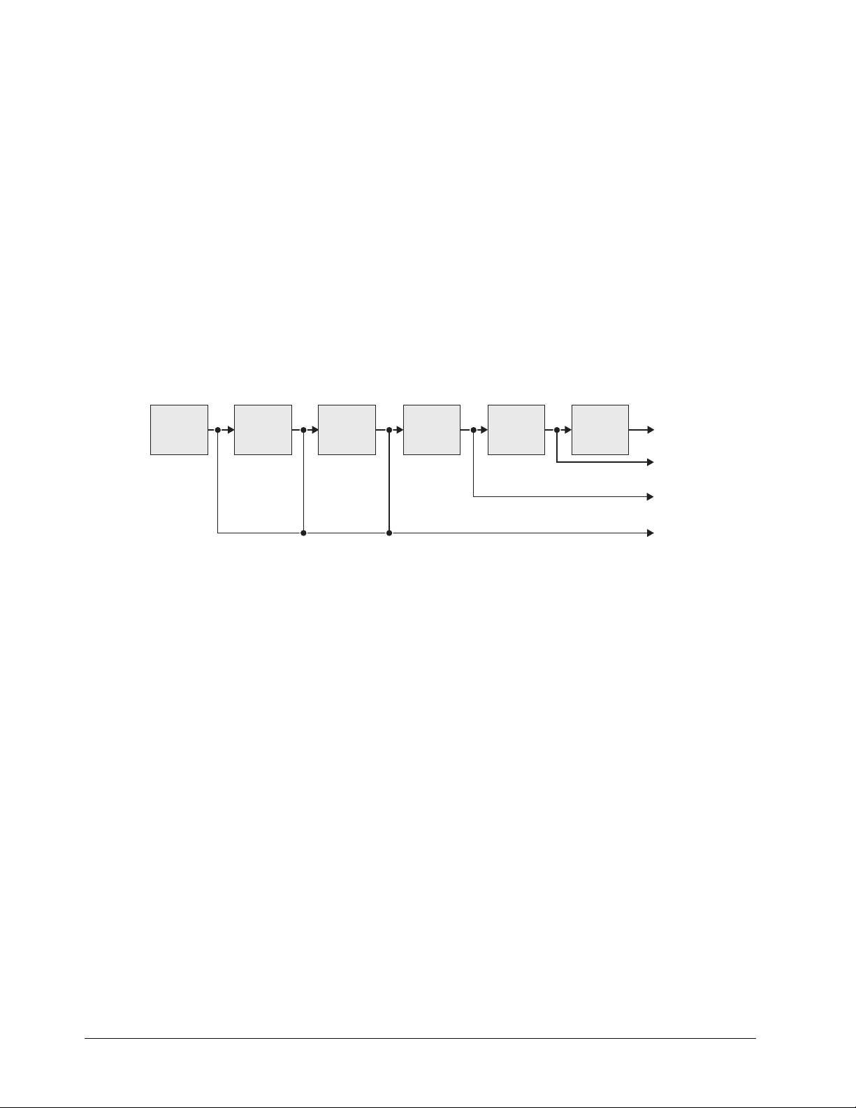
FlexiClean™ MLE Clean Feed Output
This feature is used for bilingual and live-to-tape productions. It provides a second “program” output
that is derived from a different location than the standard program output. A frequent application is
the recording of shows for later airing without “call in” phone numbers inserted.
The clean feed can come from before or between the Keyers. The diagram below illustrates the
possible clean feed configurations with the MultiDSK™ (DSK 4 and DSK 5) installed.
BKGD
PST
KEY 1 KEY 2 DSK 1 MultiDSK 4 MultiDSK 5
Clean Feed Modes in MultiDSK
PGM
CLEAN
FEED 2
CLEAN
FEED 1
FLEXI-
CLEAN
Effects Functions (Preview Overlay)
The Effects function makes it possible to present various types of useful information on the two
preview outputs. The overlay can be displayed according to user preferences. A variety of overlay
information is available:
• The “Safe Title and Safe Action Area” overlay places a SMPTE standard safe title or
safe action area indication over the switcher’s main preview output.
~ Safe title is a box that outlines the area within which the vast majority of home TV
sets will be able to read text.
~ Safe action area is a box that outlines the region within which viewers should be
able to follow the action on the screen.
• The “Center Cross Hairs” overlay places cross hairs on the preview output to indicate
the center of the picture. It is useful in the alignment of text and other information.
Powerful and Intuitive Control Panel
The Synergy 100 MD is packed with features that make it easy and enjoyable to put together a great
production. Here’s a quick list of product highlights:
• Transition Preview — This allows you to rehearse your next transition using a wipe or
dissolve on the preview monitor before using it on air. A Ross Patent.
• 3 Axis Joystick — This is the same high quality joystick used on all our switchers. Not
only does this provide an intuitive and precise control over Squeeze & Tease MD and
1–12 • Introduction Synergy 100 MD Operator’s Manual (v7.2 MD-S100)
Page 31

MD WARP, but it’s also, great for positioning and sizing borders, masks, preset patterns,
and more.
• PST BLACK Button — This button, previously only found on large production
switchers, makes a quick dip to black, followed by the next preset transition, a snap.
• Protected Fade to Black Button — Operators frequently push buttons without looking
at the panel – they’re too busy watching the action on the monitors. One button they
really want to have a different feel is the Fade to Black button. To help them out, we
put special ridges around it.
• Trans Limit Button — Another large switcher feature, this memorizes a mid transition
hold for wipes and dissolves. When activated, the appropriate segment on the transition
progress bar beside the fader will flash to show exactly where in the transition the hold
will occur.
• DVE Button — Access to internally generated Squeeze & Tease MD and MD WARP
wipes couldn’t be easier. Access DVE transitions just like a wipe – press DVE, then a
pattern button.
• User Wipes — When the next transition is a Wipe or DVE effect, double press one of
the 10 pattern buttons to recall any of 10 user wipes or DVE effects, custom selected
from more than a hundred possible effects.
• Key Mem Button — This ensures that your linear keys are always calibrated exactly as
they were designed to look. If you want to “tweak” the clip and gain, turn Key Mem off
to get a custom look.
• Char Gen 1 and Char Gen 2 Buttons — These are your customized CG hotkeys.
Press either one and the DSK defaults its settings and selects the Character Generator of
your choice.
• Source Holds on Memory Recalls — If you hold down a source button when you
perform a memory recall, the memory comes back, but the background doesn’t change.
This is a great live feature that lets you switch a sophisticated and unpredictable
production on the fly.
• Auto DSK Drop — The Synergy 100 MD can help you do two things at once when
switching a fast paced show! When you take a new background directly to air on the
background bus, the DSK can be programmed to automatically cut off at the same time.
• Memory “Effects Dissolves” — Memory recalls can be set to recall instantly, or to
smoothly move all parameters from the current settings to the stored settings. This
feature can be used to build custom 3D WARP effects with each memory location used
to store a keyframe. For example, it’s great for flipping WARP over-the-shoulder boxes
forward to full screen!
• Pop Up Help — Don’t you hate it when you press a button, nothing happens, and you
don’t have any idea why? We do too. On the Synergy 100 MD, a short help message
pops up on the preview monitor to help you out when you have pushed an invalid
sequence of buttons.
• Tri-Color Buttons — On air sources light red, other buttons light yellow, and buttons
that currently apply to the joystick and Effects Control region light green. Easy to use,
easy to learn, looks great.
• Alphanumeric Displays — There are three assignable regions in the upper panel –
Effects Control, Mattes, and System Control. Dedicated alphanumeric displays keep you
well informed as to how they’re assigned.
Synergy 100 MD Operator’s Manual (v7.2 MD-S100) Introduction • 1–13
Page 32

• Non-Sync Indicators — These are great for system timing and advance warning of
potential problems with a source. The bus names to the left of the source buttons glow
green when everything’s okay and yellow when a source is non-sync.
• Shared Key Bus Indicators — The Key Bus source buttons can be shared three ways –
Key 1 sources, Key 2 sources, and DSK sources. Each keyer has its own independent
bus. Illuminated labels to the left of the bus keep you fully informed.
• Variable Button and Display Brightness — Not all control rooms have identical
lighting. The Synergy 100 MD buttons and displays can be custom set in the installation
menus to just the right brightness level.
• Built-in Panel Diagnostics — The Synergy 100 MD panel comes complete with an
easy to use suite of diagnostic tests. These are the same ones that we use to test it in our
factory.
100 Event Memory System
The Synergy 100 MD is equipped with a standard 100-event memory registers for complete switcher
snapshots. At the touch of a button, the entire switcher setup can be recalled using the numbered
buttons in the Effects Control Group, or the 10 and 1 buttons (in conjunction with the SEL button)
in the System Control Group.
All of these memories, including associated attributes, can be stored to the hard disk or a USB Drive,
providing custom tailored memories for every operator and every show.
Effects Dissolves
All Synergy 100 MD memories can also be used as effects dissolves. This allows you to easily
produce elaborate moving effects at the touch of a button – especially powerful with the Squeeze &
Tease MD and MD WARP options.
5 Matte Generators
The Synergy 100 MD has five simple color generators for wipes, Effects Keyers 1 and 2, COLOR
BKGD, and DSK key border. Two additional matte generators are added when you purchase Squeeze
& Tease MD and/or MD WARP.These color generators allow you to adjust the hue, color saturation,
and luminance of the BKGD, wipe pattern borders, Effects key fill, or the Downstream key border and
matte fill.
Hard Disk Drive and USB Drive
Up to 100 switcher setups, including memory functions, switcher personalities, and installation
parameters, can be stored to and recalled from the System Hard Drive or a USB Drive. This allows
operators and technical staff to easily backup their switcher setups.
The system hard disk drive is located on the CPU Board in the Synergy 100 MD frame. Switcher
settings can also be stored here for quick recall. This is the same hard disk drive that is used to store
stills, logos, animated logos, and short video clips. Memories and graphics files are accessible over
the 10/100 Ethernet network port for easy remote load and backup.
Switcher Setup Menus
Press the MENU button to bring up the setup and programming menus. These are presented in plain
English and are designed for quick navigation. The menu can be over a blue background or
transparent, showing the preview video behind it – this feature is user selectable.
1–14 • Introduction Synergy 100 MD Operator’s Manual (v7.2 MD-S100)
Page 33

Displays and Indicators
The Synergy 100 switcher always keeps you informed.
• PGM bus crosspoints are illuminated red, signifying “on-air” status, except when the
panel is faded to black. In this case, the crosspoint LEDs will be orange.
• PST bus crosspoints are lit orange, except during a background transition, when they
will be red.
• KEY bus crosspoints will be lit orange when the key is not on air, and red when the key
is contributing to the program output.
• The secret-till-lit LEDs to the left of each crosspoint bus will be lit green when the
source selected on the bus is synchronous, and orange if the source is non-synchronous.
• Functions that have control of the Effects Control groups will be lit green (e.g. FLY
KEY).
• The ON AIR secret-till-lit LEDs in the Effects Keyers group and under the key and
DSK transition buttons in the Transition Control group glow red when the key is on air.
• The EDIT secret-till-lit LED under the MENU button in the System Control group is lit
when the Editor option is installed and enabled.
• The auto transition rate in the System Control group is constantly visible.
• When the switcher is in “memory mode”, the last memory register accessed is displayed
in the System Control group.
• The four-character MODE displays in the Effects Control, Mattes, and System
Control groups, always inform you of which function has control of each group.
• The LEDs in the Transition Progress Bar show you how far the transition has
progressed, and which direction the fader must travel to complete it.
General Purpose Interface
The Synergy 100 MD is equipped with ten dedicated GPI inputs. Each GPI input can be used to
perform simple editing and switcher functions such as fade to black, an auto transition, and a memory
recall.
Note
GPI outputs are not implemented as this time.
Emergency Bypass Relays
The Synergy 100 MD frame also includes 2 dedicated power-fail relays. These normally closed relays
open in the event of a power failure, or other system fault that prevents a reliable program output (for
example, removal of a Video Output card). These relays can be used to control an external emergency
routing system.
Control Panel Tallies
Sixteen tallies come standard with the Synergy 100 MD control panel.
10 Meter Control Cable
The Synergy 100 MD control panel and rack frame are connected by a single, standard 8-pin
flat-shielded Telco cable that uses RS-422 communication. The maximum cable length between the
control panel and its rack frame is 1,000 feet or 305 meters.
Synergy 100 MD Operator’s Manual (v7.2 MD-S100) Introduction • 1–15
Page 34

Synergy Slots
The Synergy 100 MD incorporates a special mode in which pseudo-random information is statistically
measured on a cumulative basis.
System Options
This section lists the options available for the Synergy 100 MD. All options can be easily installed in
the field.
Note
Refer to Chapter 15 “Hardware Options” in the Synergy 100 MD
Engineering Manual for instructions on how to verify the status of
your installed hardware options.
Conversion Frames
All switcher inputs and outputs are 10-bit 4:2:2 serial digital, including the system reference. Signal
sources of other video formats must be converted to serial digital. Ross Video chose to do this
conversion externally to ensure that the very latest conversion technology and most competitive
pricing is available to our customers. An added bonus of external conversion is the ability to use those
converters elsewhere in your facility as you eventually upgrade your switcher sources to serial digital.
The table below lists the Ross products that qualify as converters.
Converter Description
ADC-8032B Analog Composite to SDI Digital Decoder
ADC-8032B-S Analog Composite to SDI Digital Decoder with Frame Sync
ADC-8033 Analog Component to SDI Converter
ADC-8035 Dual Analog Composite to SDI Converter
CMA-8011A SDI Component Monitoring Amplifier
CMA-8011A-7 SDI Component Monitoring Amplifier with 7 reclocked SDI Outputs
DAC-8013 SDI to Analog Component Converter
DAC-8016A SDI to Analog Composite Converter
DAC-8016A-S SDI to Analog Composite Converter with Frame Sync
DAC-8016A-SX SDI to Analog Composite Converter with Frame Sync and X-Color Filter
DAC-8016A-X SDI to Analog Composite Converter with X-Color Filter
QMA-8044 Quad SDI to Analog Composite Monitoring Amplifier
UMA-8017 Universal SDI Monitoring Amplifier
Please visit our web site or contact your Ross Video representative to obtain a current Ross Video
Product Catalog for detailed information on our complete line of converters.
Squeeze & Tease MD Carrier
This is an optional carrier card equipped with a high performance DSP (Digital Signal Processing)
module. One of these cards must be purchased in order to install the Squeeze & Tease MD or Squeeze
& Tease MD WARP option cards.
1–16 • Introduction Synergy 100 MD Operator’s Manual (v7.2 MD-S100)
Page 35

Squeeze & Tease MD
One Squeeze & Tease MD option provides two channels of 3D planar effects. The Synergy 100 MD
can have up to two of these options, providing an impressive 4 channels of 3D DVE.
Note
The following are some of the functions you will be able to do with the Squeeze & Tease MD option:
Fly ANY kind of Key
Pressing the FLY KEY button easily activates Squeeze & Tease MD allowing you to transform self
Keys, linear Keys, and chroma Keys. A comprehensive and intuitive menu is available where you can
set up your desired effects. If you prefer, the 3-axis joystick can also be used to adjust your Key’s
parameters.
Preprocessor Effects
Preprocessor effects include wide range defocus with separate H and V controls, mosaic,
posterization, colorization, and a strobe effect that allows you to vary the number of on and off frames
to provide enhanced creative possibilities. All preprocessor effects are available to be combined
simultaneously.
Lighting
All images and Keys can also have realistic natural lighting applied to them. Squeeze & Tease MD
makes it easy with “quick presets”, a positionable light source, and powerful ambient and min/max
lighting controls.
Advanced Picture Frame Border Generator
Squeeze & Tease MD can add a picture frame to border over-the-shoulder boxes. This variable width
border perfectly tracks all image resizing and special effects. The picture frame generator instantly
adds a polished, professional look to your squeeze backs.
The Squeeze & Tease MD can only be installed on the Squeeze &
Tease MD Carrier board.
This picture frame can be the simple, single color type, or one of many picture frame effects including
roman column, tubular, beveled, computer style, tri-color, and more. These picture frame effects have
the following adjustable controls:
• hard or variable edge softness
• edge width/scaling
• inside/outside edge softness symmetry
• diagonal, horizontal, and vertical corner joint selection
• full control of all three picture frame color generators.
Advanced Planar Controls
The following advanced controls make building the ideal look for your show just that much easier:
• Front Side/Back Side — When you look at the backside of an effect, you can have it
automatically select a different video signal on the Key bus. This makes it possible, for
example, to rotate between 2 channels of still store in an over-the-shoulder box in a
single Keyer, using only 1 channel of S&T MD.
• Auto Flip — When you rotate an image in normal mode, the backside appears upside
down or mirrored. Turning on Auto Flip ensures that the front side of an image is always
presented. This is great for the manipulation of still store and CG text.
Synergy 100 MD Operator’s Manual (v7.2 MD-S100) Introduction • 1–17
Page 36

• Internal Key Combiner — Squeeze backs can be combined and displayed in a single
Keyer. This effectively adds additional Keyers to the Synergy MLE.
• Key Combiner Priority Control — Getting the channels the way you want them is
easy with S&T MD. When several squeeze backs are combined in a single Keyer, you
can choose fixed priorities, auto-priority, or intersecting planes. Auto-priority
automatically calculates the channel priority based on their relative positions in 3D
space. With the intersecting planes choice, channels will literally cut into one another
channel hiding the portions that are hidden behind them.
Pre-Built Effects, User-Built Timelines, and Key Sequences
Squeeze & Tease MD ships with dozens of prebuilt effects that are ready to take to air. More effects
can be downloaded from our website. All of these effects can be easily user modified to meet your
needs. You can also build entirely new effects of your own from scratch.
Effects can be built to start when a macro button is pressed, when an auto transition is pressed, or can
be run under manual fader control. Effects can be used as a transition, or as a sequence of Keyframes
running inside one or more Keyers.
Squeeze & Tease MD WARP
Squeeze & Tease MD WARP adds extensive curvilinear effects to an MLE with Squeeze & Tease MD
installed. These effects can be applied to transitions or Keys where a planar channel or Key-combined
group of channels is being used.
Note
The Synergy 100 MD Switcher will support only one S&T WARP
option.
WARP Effects
WARP effects include such ones as page turn, ripple, wave, mirror, melt, lenses and many more.
The creative possibilities are endless as S&T MD WARP effects can be easily combined with
preprocessor, planar transformation, lighting and picture frame effects.
Assignable Remote Aux Panels
A Remote Aux Panel is a self-contained switching unit that has its own power supply. It mounts in a
19-inch rack and fills one RU (Rack Unit).
An Assignable Remote Aux Panel controls multiple Aux Bus outputs.
BLACK SHIFT
MLE
PV
CLN
FEED
PGMPV
ASSIGN1ASSIGN2ASSIGN3ASSIGN4ASSIGN5ASSIGN6ASSIGN7ASSIGN8ASSIGN9ASSIGN
Synergy 100 MD Remote Aux Panel
The Remote Aux Panels include dedicated buttons for Preview, Program, Clean Feed, and for
accessing multiple Aux Bus Outputs — plus a bright “on-air” LED.
10
1–18 • Introduction Synergy 100 MD Operator’s Manual (v7.2 MD-S100)
Page 37

The following features will affect the positioning of Remote Aux Panels in relation to the control
panel:
• The Assignable Aux panel options include a 33-foot (10 meter) cable, but custom
lengths, up to a maximum of 1000 feet or 305 meters (as limited by RS-422
specifications), between panels is possible. Contact Ross Video for details.
• The communications signal is re-buffered at each Remote Aux Panel.
• Remote Aux Panel assignments are performed using the control panel and menu system.
Refer to the section “Setting Up Remote Aux Panels” in the Synergy 100 MD
Engineering Manual for more information.
MultiDSK (DSK 4 and DSK 5)
This option adds a fourth and a fifth linear Downstream Keyer to the standard internal DSK. These
Downstream Keyers have access to every video source, and are fully integrated into the transition
system with full preview.
The hardware for this option resides on the Video Output Board, and will consume four Output BNCs
to supply the DSKs with Video and Key sources.
Editor and Automation Interface
It is common to use an editor to control a video production switcher in linear editing and packaging
applications. With the editor interface option, the Synergy 100 MD can interface to all popular editing
systems. Any area of the switcher can be controlled using an RS-232 or RS-422 interface and
industry-standard GVG 100, 200, or 4000 editor protocol. The editor can be used to read and write
switcher functions including video input selection, pushbutton enable and disable, control settings,
and memory registers. If complete control of all switcher parameters from an editor or remote device
is necessary, this option is required.
Note
An alternative to the serial interface is GPI triggers, which come
standard with the Synergy 100 MD. GPIs can be programmed to press
cut or auto transition buttons directly.
Small Audio Mixer Interface
This option enables serial control for enhanced audio-follow-video from the Synergy 100 MD
switcher over small audio mixers, allowing integrated A/V production possible.
You can purchase the small but powerful Yamaha 01V96 audio mixer console through any Ross Video
distributor. This mixer has up to 16 analog inputs, 16 digital inputs, and a proven interface to our
production switchers.
Note
On the Synergy 100 MD switcher, this is a simple audio-follow-video
interface. Larger Synergy MD/MD-X models offer a more
comprehensive interface.
Serial Tally Interface
This option enables Serial Tally Interface using industry standard protocols to Under Monitor Display
and Tally Systems. The standard parallel tally interface will continue to operate normally when this
option is enabled.
Synergy 100 MD Operator’s Manual (v7.2 MD-S100) Introduction • 1–19
Page 38

Control Panel Redundant Power
This provides a spare “quick swap” power supply for the Synergy 100 MD control panel. The control
panel power supply consists of a custom external “brick” which includes a locking connector. It can
be easily changed in a few seconds.
Frame Redundant Power
This option provides redundant power for those who have replaced or upgraded their frame and
already have redundant power for their panel.
Spare Parts Kit
A Spare Parts Kit is available which provides switcher parts according to the following criteria:
• the part comes into frequent contact with the user
• the part can be easily damaged or may wear out with excessive use
• the part can be damaged by connecting excessive voltage to an external connector
• the part is used in system power management
• the part can be lost easily
Custom Cable for Main Control Panel
The Control Panel cable connects the control panel to the electronics frame. It is a shielded 8-pin
RJ-45, CAT5 cable. The control panel and frame can be separated by a maximum of 300 meters.
A 10 meter control panel cable is supplied as standard with the switcher. If cable lengths other than 10
meters are needed, a custom cable can be ordered (by the meter).
1–20 • Introduction Synergy 100 MD Operator’s Manual (v7.2 MD-S100)
Page 39

A Word about Technical Support
At Ross Video, we take pride in the quality of our products, but if problems occur, help is as close as
the nearest telephone.
Our 24 Hour Hot Line service ensures you have access to technical expertise around the clock.
After-sales service and technical support is provided directly by Ross personnel. During business
hours (eastern standard time), technical support personnel are available by telephone any time. After
hours and on weekends, a direct emergency technical support phone line is available. If the technical
support personnel who is on call does not answer this line immediately, a voice message can be left
and the call will be returned shortly. These people are available to react to any problem and to do
whatever is necessary to ensure customer satisfaction.
For Technical Support, call (+1) 613-652-4886 and, for After Hours Emergency, dial (+1)
613-349-0006.
Synergy 100 MD Operator’s Manual (v7.2 MD-S100) Introduction • 1–21
Page 40

Product Comparison Charts
As a comparison, the following tables detail the features and options that are available with the
different Synergy MD switchers with no optional equipment.
Feature 100 MD 1 MD 1.5 MD 2 MD 2.5 MD
Number of MLEs 11223
Number of MLE Keyers 2 2 2* 2 4*
Input BNCs 16 16 (+16) 16 (+16) 16 (+16) 16 (+16)
Output BNCs 16 16 16 16 16
Panel Accessible Inputs 16 30 32 32 32
UltraChrome Chroma Keying Yes Yes MLE 1 MLE 1 and 2 MLE 1 and 2
Custom Control Buttons None 24 17 17 30
Programmable Custom Controls None 128 72 72 176
Number of MLE Keyers22224
Number of DSKs 1 (+2) (+2)† 2 (+2)* 2 (+2) 2 (+2)*
DSK Self Keys Yes -- Yes Yes Yes
DSK PST PATT Keys No -- No Yes No
DSK Auto Select Key Yes -- Yes Yes Yes
DSK Chroma Key No -- No Yes No
Button Accessible Aux Buses on
Control Panel
Mnemonics Available No No Yes Yes Yes
Control Panel Tallies 16 16 36 (+36) 36 (+36) 36 (+36)
102 323232
Numbers in ( ) represent optional upgrades that are available.
* There is reduced functionality on the Keyers of the Half MLE.
† The Synergy 1 MD does not have Downstream Keyers as standard. The MultiDSK option must be
installed in order to use the Downstream Keys.
1–22 • Introduction Synergy 100 MD Operator’s Manual (v7.2 MD-S100)
Page 41

Control Panel Introduction
In This Chapter
This chapter provides an introduction to the Synergy 100 MD control panel. The following topics are
discussed:
• Control Panel Sections
• Video Flow through the Switcher
• Switcher Timeout
• Resetting the Switcher
• Shutting Down the Switcher
• Restarting the Switcher
Synergy 100 MD Operator’s Manual (v7.2 MD-S100) Control Panel Introduction • 2–1
Page 42

Control Panel Sections
The following figure displays a top view of the Synergy 100 MD control panel, with each control
panel section identified. The legend beneath the illustration names each section.
10
4
3
EFFECTS CONTROL MATTES SYSTEM CONTROL
SEL
CNTR
REV
506172839
FLY
SELF
KEY
MASK
KEY
AUTO
SELECT
KEY
INVERT
MATTE
FILL
CHROMA
KEY
ROTATE
4
2
ASPECT
KEY1
KEY2
BLACK SHIFT
DSK
PGM
BLACK
MEM
ASPECT
KEY2
PATT
ON AIR
4
PST
TRANSP
SHIFT
HUE/
GAIN
CLIP
5
BACKMENUSEL
DVE
MATTESEFFECTS KEYERSEFFECTS CONTROL
HUE
SAT
LUM CLIP GAINSOFT BORDER
BKGD KEY1 KEY2
ON AIR ON AIR ON AIR ON AIR
DISS
WIPE
EDIT
DVE
100 10 1
DOWNSTREAM KEYER
KEY
MATTE
MEM
FILL
SELF
AUTO
KEY
SELECT
KEY
MASK
INVERT
CHAR
GEN1
1
PST
BLACK
BUSY
SHIFT
AUTO
CUT
TRANS
TRANSITION CONTROL
SHDWBORD OUTL
CHAR
GEN2
TRANS
LIMIT
DSK
CUT
ON AIR
65
SEL
BLACK
FADE
BLACK
DSK
DISS
PV
PST
TO
DSK
7
9 8
Synergy 100 MD Control Panel
1) Program/Preset Buses
2) Key Bus
3) Effects Keyers Group
4) Memory and Effects Control Groups
5) Mattes Groups
6) System Control Group
7) Downstream Keyer Group
8) Transition Control Group
9) USB Port
10) Positioner
1. Program/Preset Buses
The Program/Preset Buses are two rows of crosspoint buttons (one button per video
input source) that represent your primary switcher output selection area.
• The Program bus is the video source currently on air. This is the background image
— that is, the image that is visually behind all other images (or farthest upstream,
electronically).
• The Preset bus selects the source on the MLE that you are transitioning to — using
a cut, dissolve, wipe or DVE transition.
2–2 • Control Panel Introduction Synergy 100 MD Operator’s Manual (v7.2 MD-S100)
Page 43

2. Key Bus
The Key Bus row is used to select key sources that can be keyed (electronically cut) into
the background. The Key bus is shared between the three keyers (two Effects Keyers
and a Downstream Keyer).
3. Effects Keyers Group
The Effects Keyers Group allows you to select the key type and associated parameters
for the Effects keys. Choose between Self Key, Auto Select Key, Chroma Key, and
PST PATT Key. Within the group, you can also select a variety of key modifiers and
parameters. When any button is selected in the group, the Key bus is assigned to the
Effects Keyers.
Electronically, the Effects Keyers are downstream (visually in front) of the background
buses, but upstream (visually in back) of the Downstream Keyer.
Note
4. Memory and Effects Control Groups
5. Mattes Groups
6. System Control Group
7. Downstream Keyer Group
The Effects Keyers Group is used to set up both Key 1 and Key 2.
Each key can be set to a different key type, if desired, and have its own
individual set of key modifiers and parameters.
The Memory and Effects Control Groups are assignable groups of controls that allow
you to choose wipe patterns and adjust various parameters of the selected pattern. In
addition, the pattern buttons are used to store and recall switcher parameters, and as a
means of navigation within the switcher menu system.
The Mattes Groups are assignable modules that allow you to adjust matte colors. By
pressing any matte-related button on the switcher, or the SEL button beneath the Mattes
display, the Mattes groups are assigned.
The System Control Group includes the SEL button, which, when used in conjunction
with the 100, 10, and 1 buttons, allows the user to navigate through the menu system
and assign transition rates to AUTO TRANS, DSK DISS and FADE TO BLACK auto
transitions. The MENU button is used to access the menu system of the Synergy 100
MD switcher.
The Downstream Keyer Group allows you to select the key type and associated
parameters for the Downstream Key (DSK). Choose between Self Key or Auto Select
Key.
The
CLIP knob adjusts the luminance, or threshold, level of the key and the GAIN knob
adjusts the sharpness or softness of the edges of the key.
With the XFX Board with Dual Border option installed, the BORD, SHDW, and
OUTL buttons place a border, drop shadow or outline around the Key.
Note
Synergy 100 MD Operator’s Manual (v7.2 MD-S100) Control Panel Introduction • 2–3
The XFX Board with Dual Border option is not yet implemented.
In addition, there are CHAR GEN1 and CHAR GEN2 buttons, which allow you to
pick your favorite CGs for immediate keying.
Page 44

When any button is selected in the group, the Key Bus is assigned to the Downstream
Keyer. An ON AIR LED under the DSK CUT and DSK DISS buttons in the
Transition Control Group, indicates when the downstream key is contributing to the
program output.
Electronically, the Downstream key is downstream (visually in front) of both the
background buses and the Effects keys.
8. Transition Control Group
The Transition Control Group allows you to select the type of transition that you want
to perform between the current scene and the next scene. You can transition any
combination of the Program/Preset and Key buses using a cut, wipe, or dissolve.
The DVE button allows you to perform transitions using effects from an optional
Squeeze & Tease daughter board. Transitions can be performed manually with the
Fader or automatically with the AUTO TRANS button.
The Fade to Black button allows you to fade the switcher to black.
Note
9. USB Port
10. Positioner
If you have the MultiDSK Option installed, the TRANS LIMIT and
PST BLACK buttons will be changed to DSK4 DISS and DSK5
DISS, respectively and the Transition Limit and PST Black features
will be unavailable.
The USB Port allows you to store and recall your entire switcher setup to and from a
USB Drive.
The Positioner allows you to position wipe patterns on screen. By pressing the WIPE
button in the Transition Control Group or the PST PATT button in the Effects Keyers
group, the Positioner is assigned. If the Squeeze & Tease MD or Squeeze & Tease
WAR P M D option is installed, the Positioner can be used to manipulate the X, Y, and in
the case of the Squeeze & Tease WARP MD option, the Z position of a Squeeze &
Tease MD Key.
2–4 • Control Panel Introduction Synergy 100 MD Operator’s Manual (v7.2 MD-S100)
Page 45

Video Flow through the Switcher
The following diagram shows how video flows through your switcher, and illustrates the visual and
electronic concepts of upstream and downstream video images.
Input
Video
MLE Background
(Program/Preset Bus)
Effect Key 1
Effect Key 2
DSK 1
Multi-DSK 2
Multi-DSK 3
Fade to Black
Switcher
Output
Synergy 100 MD Video Flow (with Optional MultiDSK installed)
The Synergy 100 MD is a single MLE switcher with 16 standard inputs. Video flows into the MLE, as
indicated above, where crosspoints can be selected for effects creation.
The Program and Preset buses are electronically the farthest upstream, the Effects Keys appear mid
stream and the Downstream Key appears downstream.
• Visually, all images on the Background bus appear behind both keyers. A key enabled on
the Effects Keyer appears visually over the Background bus (and all transitions), but
visually under the Downstream Keyer.
• A key enabled on the Downstream Keyer appears visually over the Background bus and
the Effects Keys.
• The Fade to Black function is electronically downstream of the entire switcher.
Regardless of the combination of keys selected, Fade to Black will visually take the
entire switcher to black.
Synergy 100 MD Operator’s Manual (v7.2 MD-S100) Control Panel Introduction • 2–5
Page 46

Switcher Timeout
If no control panel buttons are touched and no fader arms are moved for a period of 10 minutes, the
switcher goes into a “sleep” mode and all lights are automatically turned off. This function is
specifically designed to extend the life of the displays and the button LEDs.
If this timeout occurs, press any button or move the fader or joystick to “wake” the switcher and turn
on all lights.
Note
The factory default timeout interval is 10 minutes. For instructions on programming an alternate
timeout interval, refer to the Synergy 100 MD Engineering Manual.
The switcher does not act on a button push when it is coming out of
“sleep” mode.
2–6 • Control Panel Introduction Synergy 100 MD Operator’s Manual (v7.2 MD-S100)
Page 47

Resetting the Switcher
If required, you can perform a software reset to clear all effects and crosspoint selections currently
active.
Important
Performing a Reset will set all crosspoints to Black, including the main
PGM output.
The software reset function is performed in the Effects Control Group and System Control Group.
EFFECTS CONTROL MATTES SYSTEM CONTROL
SEL
CNTR
REV
506172839
FLY
SELF
KEY
MASK
KEY
AUTO
SELECT
KEY
INVERT
MATTE
FILL
CHROMA
KEY
KEY2
PST
PATT
ON AIR
ROTATE
ASPECT
KEY1
KEY2
BLACK SHIFT
DSK
PGM
BLACK
PST
BLACK
MEM
ASPECT
4
TRANSP
SHIFT
SHIFT
HUE/
GAIN
CLIP
DVE
MATTESEFFECTS KEYERSEFFECTS CONTROL
HUE
SAT
LUM CLIP GAINSOFT BORDER
BKGD KEY1 KEY2
ON AIR ON AIR ON AIR ON AIR
DISS
WIPE
AUTO
CUT
TRANS
EDIT
KEY
MEM
SELF
KEY
MASK
DVE
TRANSITION CONTROL
BACKMENUSEL
100 10 1
DOWNSTREAM KEYER
MATTE
BORDER
FILL
AUTO
CHAR
SELECT
GEN1
KEY
INVERT
SHDW OUTL
CHAR
GEN2
TRANS
LIMIT
DSK
CUT
ON AIR
SEL
DSK
PV
PST
BLACK
FADE
TO
BLACK
DSK
DISS
BUSY
Software Reset Function
Press and hold the CNTR button in the Effects Control Group and the SEL button in the System
Control Group to perform a software reset. Note the small “reset” symbols beside each button.
This resets the control panel to its default values. Switcher memory registers, personality registers,
and installation registers are not affected by the reset, but all other switcher parameters, such as the
current state of the panel, are reset. BLACK will be selected on all buses.
Synergy 100 MD Operator’s Manual (v7.2 MD-S100) Control Panel Introduction • 2–7
Page 48

Shutting Down the Switcher
This section provides information and instructions for safely shutting down your Synergy 100 MD
Switcher.
Important
Due to the sensitive electronics used in your Synergy 100 MD
Switcher, you should not shutdown the switcher by turning off the
power supplies. This could damage the switcher.
Use the following procedure to shutdown the switcher:
1. Navigate to the Default Menu as follows:
• Press MENU to display the Main Menu.
• Press 7. Options to display the Options Menu.
• Press 5. System Resets to display the System Resets Menu.
System Resets
0. All
1. System Shutdown
2. System Restart
3. Inputs/Outputs
4. Restart Global-Store
MENU
100
Exit
Previous10Down
Systems Resets Menu
2. Press 1. System Shutdown to display the System Shutdown Confirmation Screen.
1
Up
SEL
Accept
Are you sure you want to SHUTDOWN the system?
0. Confirm 1. Cancel
10
Down
1
Up
SEL
Accept
System Shutdown Confirmation Screen
3. Press 0. Confirm to shutdown the switcher.
Operating
Tip
Press 1. Cancel to not shutdown the switcher and return to the
Default Menu.
This completes the procedure for shutting down the switcher.
2–8 • Control Panel Introduction Synergy 100 MD Operator’s Manual (v7.2 MD-S100)
Page 49

Restarting the Switcher
This section provides information and instructions for safely restarting your Synergy 100 MD
Switcher.
Important
Due to the sensitive electronics used in your Synergy 100 MD
Switcher, you should not restart the switcher by turning the power
supplies off and on again. This could damage the switcher.
Use the following procedure to restart the switcher:
1. Navigate to the Default Menu as follows:
• Press MENU to display the Main Menu.
• Press 7. Options to display the Options Menu.
• Press 5. System Resets to display the System Resets Menu.
System Resets
0. All
1. System Shutdown
2. System Restart
3. Inputs/Outputs
4. Restart Global-Store
MENU
100
Exit
Previous10Down
Systems Resets Menu
2. Press 2. System Restart to display the System Restart Confirmation Screen.
1
Up
SEL
Accept
Are you sure you want to RESTART the system?
0. Confirm 1. Cancel
10
Down
1
Up
SEL
Accept
System Restart Confirmation Screen
3. Press 0. Confirm to restart the switcher.
Operating
Tip
Press 1. Cancel to not restart the switcher and return to the Default
Menu.
This completes the procedure for restarting the switcher.
Synergy 100 MD Operator’s Manual (v7.2 MD-S100) Control Panel Introduction • 2–9
Page 50

2–10 • Control Panel Introduction Synergy 100 MD Operator’s Manual (v7.2 MD-S100)
Page 51

Using the Menu System
In This Chapter
This chapter introduces the menu system of the Synergy 100 MD Switcher. The following topics are
discussed:
• Menu System Basics
• Menu Information
• Navigation Menus
• Option Menus
• Split Menus
• Menu System Operation
• Help Features
Synergy 100 MD Operator’s Manual (v7.2 MD-S100) Using the Menu System • 3–1
Page 52

Menu System Basics
The menu system is accessed using the System Control Group of the Synergy 100 MD control panel
and displayed on the preview monitor as a Preview Overlay.
The following figure details the panel buttons that are used to access the menus.
EFFECTS CONTROL MATTES SYSTEM CONTROL
SEL
CNTR
REV
506172839
ROTATE
1
ASPECT
MEM
SELF
KEY
ASPECT
MASK
2
FLY
KEY
AUTO
SELECT
KEY
INVERT
MATTE
FILL
3
CHROMA
KEY
KEY2
PATT
ON AIR
6
4 5
7 8
9
4
PST
HUE/
TRANSP
GAIN
CLIP
DVE
HUE
SAT
LUM CLIP GAINSOFT BORDER
BACKMENUSEL
100 10 1
EDIT
DOWNSTREAM KEYERMATTESEFFECTS KEYERSEFFECTS CONTROL
KEY
MATTE
MEM
FILL
SELF
AUTO
CHAR
KEY
SELECT
GEN1
KEY
MASK
INVERT
SHDWBORD OUTL
CHAR
GEN2
SEL
DSK
PV
1) ASPECT Button
2) SCROLL (ASPECT) Knob
3) EFFECTS CONTROL Group
1. ASPECT Button
2. SCROLL (ASPECT) Knob
3. Effects Control Group
4. MENU Button
Note
Synergy 100 MD Control Panel
4) MENU Button
5) BACK (100)
6) DOWN (10)
7) UP (1)
8) Right SEL Button
9) Display
The ASPECT button lights automatically to indicate that the Aspect knob is active and
can be used to scroll through values in the menus.
The Aspect knob can be used to scroll through the menu values.
The Pattern buttons in the Effects Control Group allow you to use the menu system to
navigate to sub-menus or select menu items by pressing the corresponding number.
Refer to the section “Menu System Operation” on page 3–7 for more information.
The MENU button turns the menu system of the Synergy 100 MD on and off. When
toggled on, the MENU button will light green and the Main Menu is displayed on the
Preview Monitor.
You must have a monitor connected to Preview with Overlay, BNC
C02, in order to view the menu system. If you have the MultiDSK
option installed, connect your monitor to BNC C07.
3–2 • Using the Menu System Synergy 100 MD Operator’s Manual (v7.2 MD-S100)
Page 53

5. BACK (100)
Pressing the BACK (100) button will return you to the previous menu or position in the
menu tree.
6.
ª (10)
Pressing the DOWN ARROW (10) button will scroll DOWN to the next item in a
selection list or to the next menu item.
© (1)
7.
Pressing the UP ARROW (1) button will scroll UP to the next item in a selection list or
to the next menu item.
8. Right SEL Button
Pressing the right SEL button will SELECT / ACCEPT your option, setup, or position
in the menu tree.
9. Display
Once you have entered the menu system, MENU appears in the four-character MODE
displays in the Effects Control and System Control Groups. This identifies the menu
system as the area of the control panel that has control of the buttons and knobs in the
Effects Control and System Control Groups.
Menu Information
There are 3 types of menus on the Synergy 100 MD Switcher that allow you to alter settings and
configure inputs and outputs. These types are Navigation Menus, Option Menus, and Split Menus.
Navigation Menus
Navigation Menus, such as the Main Menu, are used strictly to navigate from menu to menu. They
have no configuration options and will not change as you select different options.
21
Main Menu - Synergy 100 vSynergy X MD-S100
3
0. Effects
1. Inputs
2. Outputs
3. GPIs
4. Communication
MENU
100
Exit
Previous10Down
5. Disk
6. Personality
7. Options
8. S&T MD
9. Help Menu
1
Up
4
5
SEL
Accept
Navigation Menu Example — Main Menu
1) Menu Title
2) Software Version (Main Menu Only)
3) Menu Items (Headings)
4) Navigation Legend
5) Menu Background
Synergy 100 MD Operator’s Manual (v7.2 MD-S100) Using the Menu System • 3–3
Page 54

1. Menu Title
Each menu is named in the upper left corner.
2. Software Version
The Main Menu is the only one that displays the software version number in the upper
right hand corner.
3. Menu Items
Menu Items, or headings, can be selected to change their current settings, or used to
navigate to sub-menus. Menu items that do not have selections next to them will take
you to a sub-menu. Refer to the section “Option Menus” on page 3–4 for more
information on menu selections.
When a menu item is highlighted, this indicates that it is active and can be accessed
using the right SEL button. When selected, the menu item or the selection for it, will
change color to indicate that you can change the current configuration.
Note
4. Navigation Legend
5. Menu Background
Note
If a menu item is gray, it cannot be changed.
The navigation legend provides information on how to navigate to the different
sub-menus, or select menu items.
The menu background can be turned on and off for some menus. When turned on, the
images on the preview are not visible. This allows you to read the menu more easily.
Menus such as the UltraChrome Parameters Menu turn the menu
background feature off so that you can preview your Chroma Key
before taking it on-air.
Option Menus
Option Menus, such as the Inputs Menu, function in much the same way as the Navigation Menus,
except that they allow you to configure specific settings on the switcher, as well as navigate to
different menus. In many cases, these settings are dependent on each other, meaning that as you make
a selection for one menu item, the other menu items will change to indicate the current setting. In the
Inputs BNC Config Menu, for example, menu item 0. Output BNC is used to select a BNC you
want to configure. When menu item 0 is set to a BNC, all other menu items update to show the current
configuration for the BNC you selected for 0. Input.
3–4 • Using the Menu System Synergy 100 MD Operator’s Manual (v7.2 MD-S100)
Page 55

Inputs
0. Input
1. Type
2. AutoKey
1
3. Shaped
4. Aud Chan1
MENU
Exit
BNC C01
Off
Black
No
Chan 1
Chan 25. Aud Chan2
720p 59.946. Vid Format
100
Previous10Down
1
Up
2
SEL
Accept
Option Menus Example — Inputs Menu
1. Menu Items
Menu Items, or headings, can be selected to change their current settings, or used to
navigate to sub-menus. Menu items that do not have selections next to them will take
you to a sub-menu.
When a menu item is highlighted, this indicates that it is active and can be accessed
using the right SEL button. When selected, the menu item or the selection for it, will
change color to indicate that you can change the current configuration.
2. Menu Selections
Menu Selections indicate the current configuration of a menu item. The menu items can
be changed, allowing you to assign different configurations to the switcher, or to other
menu selections.
Split Menus
Split Menus, such as the Network Setup Menu, are used to adjust multiple or complex, options for a
single menu item. Split Menus are identified by a vertical line that separates the menu items from the
options. When a menu item is selected, the configurable option for that item are listed below the
vertical line. In the Network Setup Menu, for example, when you select 4. Secondary DNS, the
option for this item is displayed below the vertical line. As this option has 4 numbers that are to be
entered, it is considered a complex menu item.
Network Setup
0. IP Address
1. Subnet
2. Gateway
1
3. Primary DNS
4. Secondary DNS
2
Secondary DNS: 0.0.0.0
Use Hue to select element, Sat to adjust value.
Exit menu and reboot for settings to take effect
Navigation Menu Example — Network Setup Menu
1. Menu Items
Menu Items, or headings, can be selected to change their current settings, or used to
navigate to sub-menus. Menu items that do not have selections next to them will take
5. DHCP Off
Synergy 100 MD Operator’s Manual (v7.2 MD-S100) Using the Menu System • 3–5
Page 56

you to a sub-menu. Refer to the section “Option Menus” on page 3–4 for more
information on menu selections.
When a menu item is highlighted, this indicates that it is active and can be accessed
using the right SEL button. When selected, the menu item or the selection for it, will
change color to indicate that you can change the current configuration.
2. Menu Selections
Menu Selections for some menus are separated from the menu items by a vertical line.
This is often used when there are multiple selections for a single menu item, or if it is a
complex selection with multiple parts, as in the case of the Secondary DNS.
This concludes the discussion on the types of menus on the Synergy 100 MD. For more information
on using the menu system, refer to the section “Menu System Operation” on page 3–7.
3–6 • Using the Menu System Synergy 100 MD Operator’s Manual (v7.2 MD-S100)
Page 57

Menu System Operation
The menu system on the Synergy 100 MD allows you to set up the various inputs and outputs, as well
as communications with external devices and various peripheral settings for switcher operation.
In order to navigate through the menus of the Synergy 100 MD, you will have to learn how to access
the menu system, navigate to the various menus on the switcher, and alter the settings you find on the
menus.
The following example will show you how to navigate to the Inputs Menu and set up a particular
Input BNC:
EFFECTS CONTROL MATTES SYSTEM CONTROL
SEL
CNTR
REV
506172839
Menu Control Group — MENU Button
1. Press MENU in the System Control Group to display the Main Menu. The MENU
button will light green and the Main Menu will be displayed on the Preview Monitor.
4
DVE
Main Menu - Synergy 100 vSynergy X MD-S100
0. Effects
1. Inputs
2. Outputs
3. GPIs
4. Communication
EDIT
5. Disk
6. Personality
7. Options
8. S&T MD
9. Help Menu
BACKMENUSEL
100 10 1
SEL
2. Navigate to the Inputs Menu 1 as follows:
Operating
Tip
MENU
Exit
100
Previous10Down
1
Up
SEL
Accept
Main Menu
Menu items that do not have a menu selection next to them, and are not
part of a split menu, will display a sub-menu when selected.
• The Pattern buttons in the Effects Control Group each have a number below
them, corresponding to the numbers beside the menu items.
Synergy 100 MD Operator’s Manual (v7.2 MD-S100) Using the Menu System • 3–7
Page 58
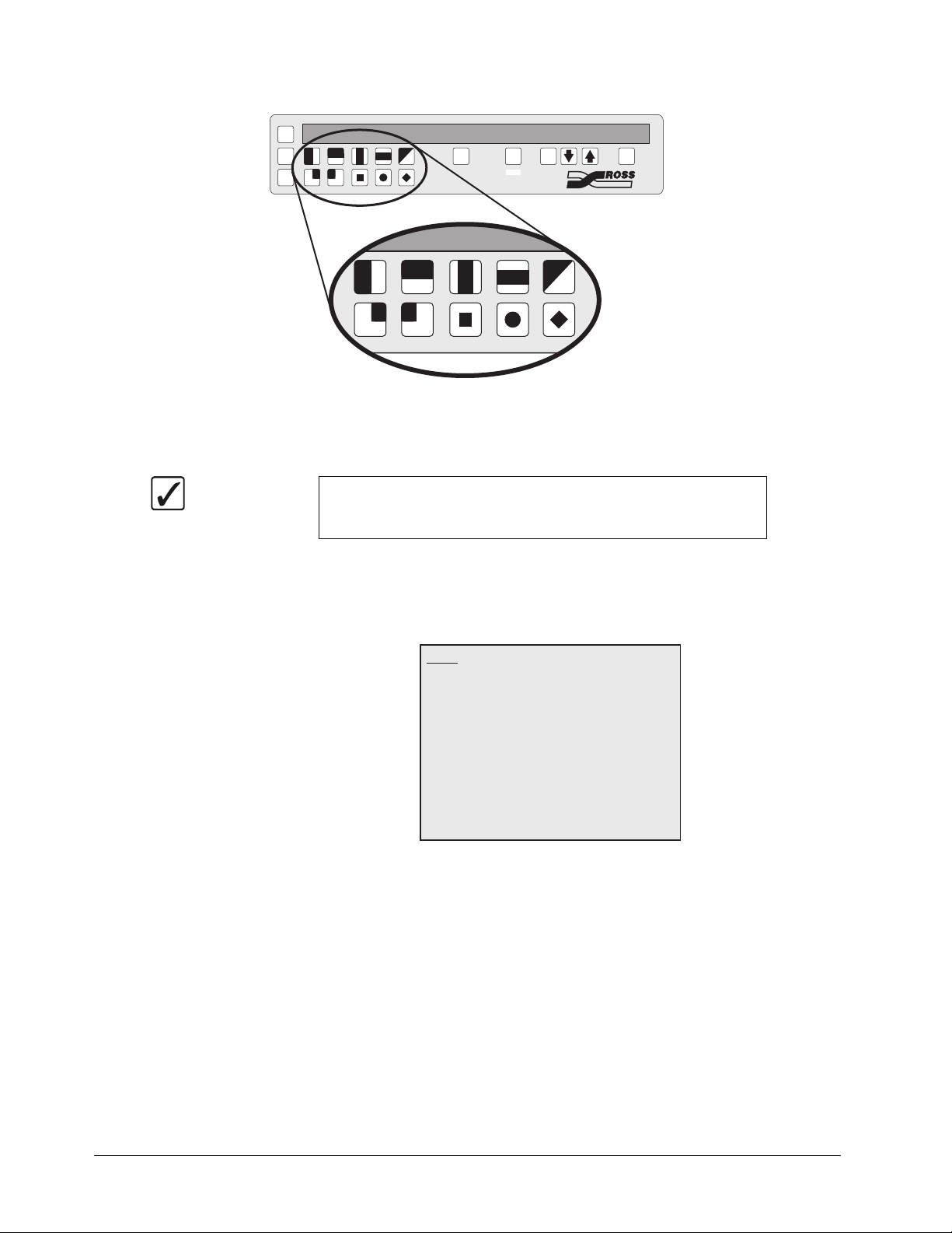
EFFECTS CONTROL MATTES SYSTEM CONTROL
SEL
CNTR
REV
506172839
4
0
5
DVE
1
6
2
7
BACKMENUSEL
100 10 1
EDIT
3
4
8
9
SEL
Effects Control Group — Pattern Button Numbers
• Press the Pattern button corresponding to the number next to the menu item that
you want to select. In this case, press the pattern button with the 1 below it.
Operating
Tip
3. Press 0. Inputs to display the Inputs Menu 2.
Navigation instructions are identified by the number next to the menu
item. In this example you will navigate to the Input Menu 1, so you
would be instructed to press 1. Inputs to display the Inputs Menu 1.
• The Inputs Menu 1 is displayed instead of the Main Menu. If the Inputs Menu 1
is not shown, you can press the BACK button to return to the Main Menu. The
BACK button will return you to the previous menu, or de-select a menu item you
have selected.
Inputs
0. Inputs
1. Panel
2. Tally
3. Audio
4. Reference
MENU
Exit
100
Previous10Down
Inputs Menu 1
1
Up
SEL
Accept
3–8 • Using the Menu System Synergy 100 MD Operator’s Manual (v7.2 MD-S100)
Page 59

Inputs
0. Input
1. Type
2. AutoKey
3. Shaped
4. Aud Chan1
MENU
100
Exit
Previous10Down
BNC C01
Off
Black
No
Chan 1
Chan 25. Aud Chan2
720p 59.946. Vid Format
Inputs Menu 2
1
Up
SEL
Accept
Operating
Tip
4. Select Input BNC C10 as follows:
If you are not at the correct menu, or want to start over again, you can
either press BACK until the Main Menu is displayed, or press MENU
to turn the menu system off, and then press MENU again to turn the
menu system on again. When toggled on by the MENU button, the
Main Menu is displayed on Preview Monitor.
• Now that you have navigated to the proper menu, you can select the Input BNC you
want to set up.
• Press 0. Input.
•Use the
ª and © buttons to select BNC C10.
• Press the right SEL button to accept the new settings.
Inputs
0. Input
1. Type
2. AutoKey
3. Shaped
4. Aud Chan1
MENU
Exit
BNC C10
Video
Black
No
None
None5. Aud Chan2
720p 59.946. Vid Format
100
Previous10Down
1
Up
SEL
Accept
BNC C10 — Inputs Menu 2
•With BNC C10 active, all the menu selections apply to this particular BNC. If you
change the active BNC again, the menu selections will update to reflect the new
BNC.
5. Change the Typ e for BNC C10 to Alpha as follows:
• Press 1. Type.
•Use the
Operating
Tip
ª and © buttons to select Alpha.
Alpha — Select this option when an alpha signal (also known as a
“Key” signal) is connected to the frame. Devices such as DVEs,
Character Generators, Graphics (Paint) Systems, and Still Stores
typically provide unique alpha signals.
Synergy 100 MD Operator’s Manual (v7.2 MD-S100) Using the Menu System • 3–9
Page 60

• Press the right SEL button to accept the new settings.
Inputs
0. Input
1. Type
2. AutoKey
3. Shaped
4. Aud Chan1
MENU
Exit
BNC C10
Video
Black
No
None
None5. Aud Chan2
720p 59.946. Vid Format
100
Previous10Down
1
Up
SEL
Accept
BNC C10 — Inputs Menu 2
• You have now set BNC C10 up as an Alpha. Other configuration changes are
made to this, and other menu items in the same manner as you have just performed.
Now that you have finished configuring the BNC, you will want to exit the menu
system.
6. Press MENU to display the Installation Change Screen. Whenever you change any of
the switcher settings, you will be asked to confirm these changes when you exit the
menu system. In this case, since we changed BNC C10 to an Alpha, the switcher
requires us to confirm this change.
WARNING!
You are about to change the switcher's
installation settings.
0. Confirm 1. Cancel
10
Down
1
Up
SEL
Accept
Installation Change Screen
7. Accept or cancel these changes as follows:
Important
As this has been an example, you should press 1. Cancel so as not to
change the setting of your Synergy 100 MD switcher.
• Press 0. Confirm to accept the changes.
• Press 1. Cancel to exit the menus safely, without making any changes. The system
returns to the previously stored settings.
This completes the example procedure for navigating to the Inputs Menu and setting up a particular
BNC.
3–10 • Using the Menu System Synergy 100 MD Operator’s Manual (v7.2 MD-S100)
Page 61

Help Features
A help feature is provided for convenient online asisstance as you operate your Synergy 100 MD
switcher.
Help Menu
The Help Menu provides a list of important “hidden” switcher functions. For example, you can
access instructions to use the two-button Copy Key function.
When a function is selected, information about the requested function is displayed in the lower half of
the menu screen.
Use the following procedure to access and browse the Help Menu:
1. Navigate to the Help Menu as follows:
• Press MENU to display the Main Menu.
• Press 9. Help Menu to display the Help Menu.
Help Menu
Copy Key
Key Swap
Resetting the Switcher
Shift Buttons
Transition Preview
You can only copy key 1 onto key 2, except matte
fill color. Set up KEY 1, then press and hold the key
type button of KEY 1. Press KEY 2 Effects Keyers
group and release both buttons.
MENU
Exit
100
Previous10Down
1
Up
SEL
Accept
Help Menu
2. Use the ª and © buttons to select a function, and view information about the function
in the lower half of the menu screen.
This completes the procedure to access and browse the Help Menu.
Synergy 100 MD Operator’s Manual (v7.2 MD-S100) Using the Menu System • 3–11
Page 62

3–12 • Using the Menu System Synergy 100 MD Operator’s Manual (v7.2 MD-S100)
Page 63

Switcher Basics
In This Chapter
This chapter presents detailed basic switcher operating procedures, rules and methods.
The following topics are discussed:
• Switcher Personality
• Basic Switcher Functions
• Buttons
• Reverse SHIFT Mode
• Flip Flop Operations
•Key Bus
• On-Air Indicators
• Knobs
• Fade to Black
• Resetting the Switcher
• Software Reset
• Full Restart
• Shutting Down the Switcher
Synergy 100 MD Operator’s Manual (v7.2 MD-S100) Switcher Basics • 4–1
Page 64

Switcher Personality
From the Personality Menu you can set a number of features that affect how the switcher will operate
or react to certain situations. These include the ability to perform a transition preview, auto recall, or
how the switcher will react to certain button presses, such as DSK drop or the menu button. You will
also use the Personality Menu to set the sleep time for the switcher.
The following topics are discussed:
• Transition Preview
•DSK Drop
• Sleep Time
• Menu Button Operation
• Auto Recall
• Global-Store Memory Recall
• Isolate MultiDSK
Transition Preview
The Transition Preview (TransPV) feature allows you to preview a complete transition on the Preview
Monitor, without affecting the Program output.
Use the following procedure to enable the transition preview feature.
1. Navigate to the Personality Menu as follows:
2. Enable the transition preview feature as follows:
Operating
Tip
• Press MENU to display the Main Menu.
• Press 6. Personality to display the Personality Menu.
Personality - Synergy 100
0. Trans PV
1. DSK Drop
2. Sleep Time
3. Menu Bttn
4. AutoRcall
MENU
100
Exit
Previous10Down
On
10 min
Menu Only
On
5. GstoreMem On
6. Isolate DSK Off
SEL
1
Accept
Up
Personality Menu
• Press 0. Trans PV.
• Press the right SEL to toggle this feature On or Off.
To perform a Transition Preview, press and hold the transition type
button (DISS or WIPE) while performing the transition. The complete
transition will be displayed on the Preview Monitor.
This completes the procedure for enabling the auto transition feature.
4–2 • Switcher Basics Synergy 100 MD Operator’s Manual (v7.2 MD-S100)
Page 65

DSK Drop
The Downstream Keyer Drop (DSK Drop) feature allows you to have the DSK cut off-air whenever a
new source is selected directly on the Program Bus. This means that is the DSK in on-air and you
select any crosspoint on the Program Bus, the DSK will be cut off-air and the new source on the
Program Bus will be cut on-air.
Note
The DSK Drop feature will not affect the DSK if a transition is
performed on the Program Bus, or if the same crosspoint button on the
Program Bus is pressed.
Use the following procedure to enable the DSK drop feature.
1. Navigate to the Personality Menu as follows:
• Press MENU to display the Main Menu.
• Press 6. Personality to display the Personality Menu.
Personality - Synergy 100
0. Trans PV
1. DSK Drop
2. Sleep Time
3. Menu Bttn
4. AutoRcall
MENU
100
Exit
Previous10Down
On
Manual
10 min
Menu Only
On
5. GstoreMem On
6. Isolate DSK Off
1
Up
Personality Menu
2. Enable the DSK drop feature as follows:
• Press 1. DSK Drop.
• Press the right SEL button to toggle this feature between Auto or Manual.
~ Auto — Select this option to have the DSK automatically cut off-air when a
new source is selected on the Program Bus.
SEL
Accept
~ Manual — Select this option to have the DSK take no action when a new
source is selected on the Program Bus.
This completes the procedure for enabling the DSK drop feature.
Sleep Time
The Sleep Time feature allows you to set the amount of time that must pass without the control panel
being used before the control panel goes into Sleep Mode. In sleep mode the buttons and displays on
the control panel will not be lit and
Note
Synergy 100 MD Operator’s Manual (v7.2 MD-S100) Switcher Basics • 4–3
Having the switcher go into sleep mode, or pressing a button to bring
the switcher out of sleep mode, will not affect the current settings of
the switcher.
Page 66

Use the following procedure to enable and set the sleep time feature.
1. Navigate to the Personality Menu as follows:
• Press MENU to display the Main Menu.
• Press 6. Personality to display the Personality Menu.
Personality - Synergy 100
0. Trans PV
1. DSK Drop
2. Sleep Time
3. Menu Bttn
4. AutoRcall
MENU
100
Exit
Previous10Down
On
10 min
Menu Only
On
5. GstoreMem On
6. Isolate DSK Off
SEL
1
Accept
Up
Personality Menu
2. Enable and set the sleep time feature as follows:
• Press 2. Sleep Time.
•Use the
ª and © buttons to set the time interval that must pass before the switcher
will go into sleep mode.
Note
Setting the Sleep Time interval to Off will disable the Sleep Time
feature.
• Press SEL in the System Control Group to accept the new setting.
This completes the procedure for enabling and setting the Sleep Time feature.
Menu Button Operation
The Menu Button feature allows you to set the action that is taken when the MENU button in the
System Control Group is pressed. You can have the switcher bring up the menu system, or enter Edit
mode when the button is pressed or double-pressed.
Note
Use the following procedure to set the action taken when the MENU button is pressed.
1. Navigate to the Personality Menu as follows:
You must have an editor set up in the communications menu in order to
be able to control the Synergy 100 MD switcher from an editor.
• Press MENU to display the Main Menu.
• Press 6. Personality to display the Personality Menu.
4–4 • Switcher Basics Synergy 100 MD Operator’s Manual (v7.2 MD-S100)
Page 67

Personality - Synergy 100
0. Trans PV
1. DSK Drop
2. Sleep Time
3. Menu Bttn
4. AutoRcall
MENU
100
Exit
Previous10Down
On
10 min
Menu Only
On
5. GstoreMem On
6. Isolate DSK Off
SEL
1
Accept
Up
Personality Menu
2. Set the action taken when the MENU button is pressed as follows:
• Press 3. Menu Bttn.
•Use the
ª and © buttons to set the action for the MENU button. You can choose
between the following:
~ Menu - Edit — Select this option to have a single press of the MENU button
bring up the Menu, and a double-press enable or disable the Editor Mode.
~ Edit - Menu — Select this option to have a single press of the MENU button
enable or disable the Editor Mode, and a double-press bring up the Menu.
~ Menu Only — Select this option to have the MENU button bring up the Menu
only. For this option you cannot enable or disable the Editor Mode with the
MENU button.
Operating
Tip
You can still enable or disable the Editor Mode from the Effects
Menu with the Menu Button set to Menu Only.
• Press SEL in the System Control Group to accept the new setting.
This completes the procedure for setting the action that is taken when the MENU button is pressed.
Auto Recall
The Auto Recall feature allows you to have memory attributes, such as Effects Dissolve (EFF DISS),
saved with the memory so that when the memory is recalled, and Auto Recall is active, Effects
Dissolve will be toggled On.
Use the following procedure to enable the auto recall feature.
1. Navigate to the Personality Menu as follows:
• Press MENU to display the Main Menu.
• Press 6. Personality to display the Personality Menu.
Synergy 100 MD Operator’s Manual (v7.2 MD-S100) Switcher Basics • 4–5
Page 68

Personality - Synergy 100
0. Trans PV
1. DSK Drop
2. Sleep Time
3. Menu Bttn
4. AutoRcall
MENU
100
Exit
Previous10Down
On
10 min
Menu Only
On
5. GstoreMem On
6. Isolate DSK Off
SEL
1
Accept
Up
Personality Menu
2. Enable the auto recall feature as follows:
• Press 4. AutoRcall.
• Press SEL in the System Control Group to toggle this feature On or Off.
This completes the procedure for enabling the auto recall feature.
Global-Store Memory Recall
The Global-Store Memory Recall feature allows you to enable or disable Global-Store Memory
Recalls on your switcher. Setting this feature to ON will recall the previously saved Global-Store
memory. Setting this feature to OFF will prevent Global-Store Memory Recalls from being
performed.
Use the following procedure to enable the Global-Store Memory Recall feature.
1. Navigate to the Personality Menu as follows:
• Press MENU to display the Main Menu.
• Press 6. Personality to display the Personality Menu.
Personality - Synergy 100
0. Trans PV
1. DSK Drop
2. Sleep Time
3. Menu Bttn
4. AutoRcall
MENU
100
Exit
Previous10Down
On
10 min
Menu Only
On
5. GstoreMem On
6. Isolate DSK Off
SEL
1
Accept
Up
Personality Menu
2. Enable the auto recall feature as follows:
• Press 5. GstoreMem.
• Press SEL in the System Control Group to toggle this feature On or Off.
This completes the procedure for enabling the Global-Store Memory Recall feature.
4–6 • Switcher Basics Synergy 100 MD Operator’s Manual (v7.2 MD-S100)
Page 69

Isolate MultiDSK
You can isolate the two MultiDSKs to prevent them from being affected by memory recalls and
switcher soft-resets. Isolated MultiDSKs also can not be included in Program/Preset-MLE transitions
(you can still transition them using the keys in the Dowstream Keyer Group. Isolated MultiDSKs are
not affected by certain actions that you perform on the switcher as follows:
• Memory Recalls — Memory registers that were saved with MultiDSK sources and
configurations will not overwrite the current MultiDSK settings when recalled. The
non-MultiDSK settings in the memory registered will be recalled.
• Switcher Soft-Reset — Performing a switcher soft-reset will not return the MultiDSKs
to a default state. All MultiDSK settings including the selected source, key type, and
on-air status will be preserved.
• Program/Preset MLE Transitions — You can not include MultiDSKs in
Program/Preset MLE transitions. You must transition the MultiDSKs on and off-air
using only the buttons in the Downstream Keyer Group.
Use the following procedure to isolate your MultiDSKs:
1. Navigate to the Personality Menu as follows:
• Press MENU to display the Main Menu.
• Press 6. Personality to display the Personality Menu.
Personality - Synergy 100
0. Trans PV
1. DSK Drop
2. Sleep Time
3. Menu Bttn
4. AutoRcall
On
Manual
10 min
Menu Only
On
5. GstoreMem On
6. Isolate DSK Off
MENU
100
Exit
Previous10Down
Personality Menu
2. Press 6. Isolate DSK to toggle this option on or off.
This completes the procedure to isolate your MultiDSKs.
1
Up
SEL
Accept
Synergy 100 MD Operator’s Manual (v7.2 MD-S100) Switcher Basics • 4–7
Page 70

Basic Switcher Functions
This section provides basic information and general rules regarding Synergy 100 MD operation. The
following topics are discussed:
• Buttons
• Reverse SHIFT Mode
• Flip Flop Operations
Buttons
There are three basic types of buttons on the Synergy 100 MD switcher; Crosspoint, Function, and
Shift buttons. These buttons will act in either a latching mode, or a momentary mode, depending on
the action they are performing.
Button Modes
There are two basic modes of button operation on the switcher, latching buttons, such as crosspoint
buttons, and momentary buttons, such as CUT or AUTO TRANS buttons. The latching buttons will
illuminate when pressed and stay illuminated until either a certain function is performed, or another
button is selected. For example, if you press a crosspoint button, it will remain lit until you press
another crosspoint button in the same bus, or you perform a transition.
Momentary buttons will illuminate when they are pressed and then turn off on their own when their
function has been completed. For example, if you press the AUTO TRANS button, it will illuminate
and the switcher will perform a transition. When the transition is complete, the AUTO TRANS
button will turn off, indicating that the Auto Transition has been completed.
Crosspoint Buttons
The crosspoint buttons are located on the Key, Program, and Preset buses on the control panel. These
latching buttons tell the switcher which video source is selected on each bus. These video sources can
be internally generated, such as BLACK and COLOR BKGD, or from external video sources that are
connected to the frame via BNC connectors. Refer to Chapter 7, “BNC Configuration and Check”
in the Synergy 100 MD Engineering Manual for details on setting up video sources.
Function Buttons
Function buttons make up the majority of the non-crosspoint buttons on the control panel and will
perform a specific function when pressed. These buttons can act in either a latching or momentary
mode, depending on the function the button is performing.
The latching buttons, such as the AUTO SELECT button in the Effects Keyers Group, will tell the
switcher to act in a certain way, depending on the button, or button combination, that is pressed.
The momentary buttons, such as the AUTO TRANS button in the Transition Control Group, will
tell the switcher to perform a certain task, and act upon the selections that have been made with the
latching buttons.
SHIFT Buttons
There are three SHIFT buttons on the Synergy 100 MD control panel, one for each bus. These shift
buttons are pressed and held in order to access video and key sources that have been mapped to
4–8 • Switcher Basics Synergy 100 MD Operator’s Manual (v7.2 MD-S100)
Page 71

crosspoints beyond the number of available buttons on each bus. The mapping itself is performed
during the installation procedure.
Note
Active crosspoints 11 through 19 can only be accessed by using the
SHIFT button. When you select a shifted crosspoint, both the
crosspoint button and the shift button will remain lit.
Use the following procedure to select a shifted crosspoint on any bus:
1. Press and hold the SHIFT button.
2. Press the desired crosspoint.
3. Release both buttons.
The SHIFT button plus the selected source both stay lit, as indicated in the illustration below.
KEY1
KEY2
DSK
Operating
Tip
BLACK SHIFT
CAM
1
Key Bus — Shifted Crosspoint Selected
VTR1VTR2VTR3CG1CG2Global
CAM
2
Store1
When a shifted crosspoint has been selected, pressing another
crosspoint button without holding the SHIFT button will select an
unshifted crosspoint.
Reverse SHIFT Mode
A special mode called Reverse SHIFT can be activated during switcher setup. Activating the
Reverse SHIFT mode makes each Key Bus button shifted all the time — as the default state. For
example, if you press any crosspoint button, without pressing the SHIFT button, the shifted crosspoint
will be taken and the SHIFT button will be lit. If you hold the SHIFT button and press a crosspoint
button, an unshifted crosspoint will be taken.
Note
The Reverse Shift Mode applies to the Key bus only. Crosspoints on
the PGM and PST buses will be unaffected.
Flip Flop Operations
The Program and Preset buses operate in flip-flop mode when a transition is performed. When you
perform a Cut, Dissolve, or Wipe transition between the Program and Preset buses, the two lit
crosspoint buttons swap places between the PGM and PST buses. This is called a flip-flop.
For example, if you select CAM 2 on the PGM bus and VTR 1 on the PST bus, CAM 2 will be on-air
and VTR 1 will be taken on-air during the next Background transition.
Operating
Tip
A Background transition is between the PGM bus and PST bus, and
does not involve the Key bus.
Synergy 100 MD Operator’s Manual (v7.2 MD-S100) Switcher Basics • 4–9
Page 72

KEY1
KEY2
BLACK SHIFT
DSK
CAM
1
VTR1VTR2VTR3CG1CG2Global
CAM
2
Store1
PGM
PST
BLACK
BLACK
CAM
1
CAM
1
VTR1VTR2VTR3CG1CG2Global
CAM
2
VTR1VTR2VTR3CG1CG2Global
CAM
2
Store1
Store1
SHIFT
SHIFT
Flip-Flop Operation — Buses Before Transition
After the Background transition is performed, the two buses switch crosspoint selections so that
VTR 1 is now on the PGM bus and CAM 2 in on the PST bus. This is a Flip-Flop.
KEY1
KEY2
BLACK SHIFT
DSK
PGM
BLACK
PST
BLACK
CAM
1
CAM
1
CAM
1
VTR1VTR2VTR3CG1CG2Global
CAM
2
VTR1VTR2VTR3CG1CG2Global
CAM
2
VTR1VTR2VTR3CG1CG2Global
CAM
2
Flip-Flop Operation — Buses After Transition
Store1
Store1
Store1
SHIFT
SHIFT
If you were to perform another background transition, the crosspoint selections would Flip-Flip back
to the original selections.
In this manner, the PGM bus always shows the crosspoint source that is on-air and the PST bus
always shows the crosspoint source that will be taken on-air during the next Background transition.
Key Bus
The Key Bus is where you select the crosspoint source for Key 1, Key 2, and the DSK. The Keyer
that has control of the Key Bus is indicated to the left of the bus by the illuminated name. In the case
of the MultiDSK option, the DSK indicator will be lit, and the Key Bus will be assigned to the DSK
that the Downstream Keyer Group is assigned to.
KEY1
KEY2
DSK
Operating
Tip
BLACK SHIFT
CAM
1
VTR1VTR2VTR3CG1CG2Global
CAM
2
Store1
Key Bus
As you switch between Key 1, Key 2, and the DSKs, the crosspoint
buttons will indicate which sources are selected for that key. If you
change a source, this will not affect the other selections.
4–10 • Switcher Basics Synergy 100 MD Operator’s Manual (v7.2 MD-S100)
Page 73

On-Air Indicators
There are several ON AIR indicators on the Synergy 100 MD control panel that indicate what is
contributing to the main Program output at any one time. These indicators are located in the Effects
Keyers Group and the Transition Control Group, as indicated in the following illustration.
EFFECTS CONTROL MATTES SYSTEM CONTROL
SEL
ROTATE
ASPECT
MEM
ASPECT
CNTR
REV
506172839
FLY
KEY
SELF
AUTO
KEY
SELECT
KEY
MASK
INVERT
MATTE
FILL
CHROMA
KEY
KEY2
PST
PATT
ON AIR
4
TRANSP
DVE
MATTESEFFECTS KEYERSEFFECTS CONTROL
HUE/
HUE
GAIN
SAT
CLIP
LUM CLIP GAINSOFT BORDER
EDIT
KEY
MEM
SELF
KEY
MASK
BACKMENUSEL
100 10 1
DOWNSTREAM KEYER
MATTE
FILL
AUTO
CHAR
SELECT
GEN1
KEY
INVERT
SHDWBORD OUTL
CHAR
GEN2
SEL
DSK
PV
KEY1
KEY2
BLACK SHIFT
DSK
PGM
BLACK
PST
BLACK
BUSY
SHIFT
SHIFT
BKGD KEY1 KEY2
ON AIR ON AIR ON AIR ON AIR
DISS
WIPE
DVE
AUTO
CUT
TRANS
TRANSITION CONTROL
TRANS
LIMIT
DSK
CUT
ON AIR
PST
BLACK
FADE
TO
BLACK
DSK
DISS
Synergy 100 MD — ON AIR Indicators
Effects Keyers Group
There is a single ON AIR indicator in the Effects Keyers Group that will be lit if the selected key in
the group is contributing to the main program output. For example, if Key 1 is on-air and Key 2 is not,
the ON AIR indicator will be lit when the KEY2 button is not selected. This means that the Effects
Keyers Group is controlling Key 1, which is on-air and so the ON AIR indicator will be lit. If you
press the KEY2 button to assign the Effects Keyer Group to Key 2, the ON AIR indicator will not be
lit because Key 2 is not on-air.
Transition Control Group
There are three ON AIR indicators in the Transition Control Group that show you if Key 1, Key 2,
or DSK 1 are on-air and contributing to the main program output.
Note
If you have the MultiDSK option installed, the two ON AIR indicators
below the TRANS LIMIT and PST BLACK buttons will show if
DSK4 or DSK5 are on-air.
Crosspoint Buttons
When you select a crosspoint on the Key, PGM, or PST buses, the selected button will illuminate to
show that it has been selected. If that bus is the PGM bus, or an on-air Key bus, the crosspoint button
Synergy 100 MD Operator’s Manual (v7.2 MD-S100) Switcher Basics • 4–11
Page 74

will be lit Red to indicate that the crosspoint is contributing to the main program output. For example,
if you select Key 1 for your next transition by pressing the KEY1 button in the Transition Control
Group, the Key bus will be assigned to Key 1 and the lit crosspoint will be taken on-air with the next
transition. If you perform a transition, you will see the crosspoint button change color from White to
Red, indicating that it is now on-air.
Knobs
There are ten rotary, end-stop, knobs on the Synergy 100 MD control panel that allow you to adjust
various values.
MATTES
HUE
End Stop
SAT
LUM
Mattes Group — End-Stop Knobs
Knobs
Each of these knobs has an upper and lower limit that it cannot be turned past. When using the knobs,
it may be necessary to re-synchronize the knob position with the electronic values you are adjusting.
Operating
Tip
To re-synchronize an End-stop Knob, turn the knob fully clockwise,
then fully counter-clockwise. Full-range adjustments can now be
made.
4–12 • Switcher Basics Synergy 100 MD Operator’s Manual (v7.2 MD-S100)
Page 75
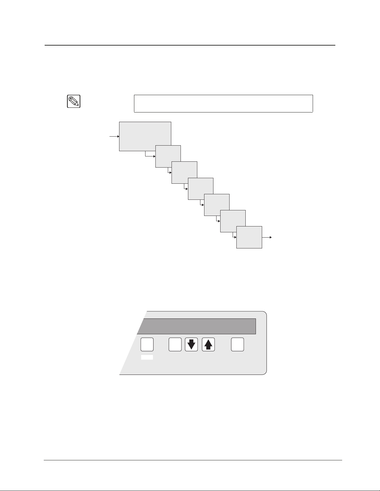
Fade to Black
The Fade to Black function allows you to perform an Auto Transition to Black for the entire Program
output of the switcher. It is the last effect that the switcher is capable of performing before the final
video signal is passed to the Program Output.
Note
Fade to Black only affects the program output of the switcher. Aux Bus
outputs or Clean Feed outputs will not be affected by Fade to Black.
Input
Video
MLE Background
(Program/Preset Bus)
Effect Key 1
Effect Key 2
DSK 1
Video Flow Through the Switcher — Fade to Black
Performing a Fade to Black
Multi-DSK 2
Multi-DSK 3
Fade to Black
Switcher
Output
Use the following procedure to perform a Fade to Black:
1. Set the Fade Rate for the Fade to Black as follows:
SYSTEM CONTROL
FADE
SEL
EDIT
120
BACKMENU
100 10 1
System Control Group — Fade Rate
• Press the SEL button in the System Control Group repeatedly until the word
FADE appears in the Mode Area.
•Use the 100, 10 and 1 buttons to set the rate for the transition in frames.
Synergy 100 MD Operator’s Manual (v7.2 MD-S100) Switcher Basics • 4–13
Page 76

2. Press the FADE TO BLACK button in the Transition Control Group.
The FADE TO BLACK button will illuminate as the transition is being performed
Note
Operating
Tip
3. Press the FADE TO BLACK button again to fade from black to the normal program
This completes the procedure for performing a Fade to Black operation.
If you want to cancel, or reverse, the Fade to Black, press the FADE
TO BLACK button again and the fade will reverse.
The FADE TO BLACK button will flash Red when the fade to black transition has
been completed.
When the switcher is in Fade to Black, you can perform any other
effects or transitions in order to prepare your shot for when you
perform a Reverse Fade to Black and return to the normal program
output.
output.
4–14 • Switcher Basics Synergy 100 MD Operator’s Manual (v7.2 MD-S100)
Page 77

Resetting the Switcher
If required, the Synergy 100 MD can be reset manually from the control panel. There are two types of
resets:
•A Software Reset affects software only
•A Full Reset affects hardware and software simultaneously
Software Reset
The software reset function is performed in the Effects Control and System Control groups. Use the
following figure for reference:
Important
ROTATE
ASPECT
KEY1
KEY2
BLACK SHIFT
DSK
PGM
BLACK
PST
BLACK
Performing a Reset will set all crosspoints to Black, including the main
PGM output.
EFFECTS CONTROL MATTES SYSTEM CONTROL
SEL
MEM
ASPECT
CNTR
REV
506172839
FLY
KEY
SELF
AUTO
KEY
SELECT
KEY
MASK
INVERT
MATTE
FILL
CHROMA
KEY
KEY2
PST
PATT
ON AIR
4
TRANSP
SHIFT
SHIFT
HUE/
GAIN
CLIP
DVE
MATTESEFFECTS KEYERSEFFECTS CONTROL
HUE
SAT
LUM CLIP GAINSOFT BORDER
BKGD KEY1 KEY2
ON AIR ON AIR ON AIR ON AIR
DISS
WIPE
AUTO
CUT
TRANS
EDIT
KEY
MEM
SELF
KEY
MASK
DVE
TRANSITION CONTROL
BACKMENUSEL
100 10 1
DOWNSTREAM KEYER
MATTE
FILL
AUTO
CHAR
SELECT
GEN1
KEY
INVERT
SHDWBORD OUTL
CHAR
GEN2
TRANS
LIMIT
DSK
CUT
ON AIR
SEL
DSK
PV
PST
BLACK
FADE
TO
BLACK
DSK
DISS
BUSY
Software Reset Function
Press and hold the CNTR button in the Effects Control Group and the SEL button in the System
Control Group to perform a software reset. Note the small “reset” symbols beside each button.
This resets the control panel to its default values. Switcher memory registers, personality registers,
and installation registers are not affected by the reset, but all other switcher parameters, such as the
current state of the panel, are reset. BLACK will be selected on all buses.
Synergy 100 MD Operator’s Manual (v7.2 MD-S100) Switcher Basics • 4–15
Page 78

Full Restart
This function performs both a hardware and a software reset simultaneously. Switcher memory
registers, personality registers, installation registers, and custom control registers are not affected by
the reset, but all other switcher parameters (for example, the current state of the panel) are reset.
BLACK will be selected on all buses.
Important
It is not recommended to reset the frame by turning the power off and
then on again as this may damage the hard disk.
Use the following procedure to perform a full restart of the switcher:
1. Navigate to the System Resets Menu as follows:
• Press MENU to display the Main Menu.
• Press 7. Options to display the Options Menu.
• Press 5. System Resets to display the System Resets Menu.
System Resets
0. All
1. System Shutdown
2. System Restart
3. Inputs/Outputs
4. Restart Global-Store
MENU
Exit
100
Previous10Down
1
Up
SEL
Accept
System Resets Menu
2. Press 2. System Restart to display the System Restart Confirmation Screen.
Are you sure you want to RESTART the system?
0. Confirm 1. Cancel
10
Down
1
Up
SEL
Accept
System Restart Confirmation Screen
3. Press 0. Confirm to restart the switcher.
Operating
Tip
Press 1. Cancel to not restart the switcher and return to the Default
Menu.
This completes the procedure for restarting the switcher.
4–16 • Switcher Basics Synergy 100 MD Operator’s Manual (v7.2 MD-S100)
Page 79

Shutting Down the Switcher
This function powers off the switcher, placing the CPU Board into a hibernation mode. In this mode it
is safe to turn off all your power supplies and remove the CPU Board.
Important
It is not recommended to shut down the frame by turning the power
off, as this may damage the hard disk.
Use the following procedure to shutdown the switcher:
1. Navigate to the System Resets Menu as follows:
• Press MENU to display the Main Menu.
• Press 7. Options to display the Options Menu.
• Press 5. System Resets to display the System Resets Menu
System Resets
0. All
1. System Shutdown
2. System Restart
3. Inputs/Outputs
4. Restart Global-Store
MENU
100
Exit
Previous10Down
System Resets Menu
1
Up
SEL
Accept
2. Press 1. System Shutdown to display the System Shutdown Confirmation Screen.
Are you sure you want to SHUTDOWN the system?
0. Confirm 1. Cancel
10
1
Down
Up
System Shutdown Confirmation Screen
3. Press 0. Confirm to shutdown the switcher.
This completes the procedure for shutting down the switcher.
SEL
Accept
Synergy 100 MD Operator’s Manual (v7.2 MD-S100) Switcher Basics • 4–17
Page 80

4–18 • Switcher Basics Synergy 100 MD Operator’s Manual (v7.2 MD-S100)
Page 81

Transitions
In This Chapter
Transitions are the most frequently used switcher operations. The simplest transition is a direct
selection of the next picture on the PGM (Program) bus, performed by pressing another crosspoint.
This simple “cut” provides an instantaneous change but does not allow you to preview the next
picture.
Other types of transitions involve the PST (Preset) bus and the controls in the Transition Control
Group. Here, using cuts, dissolves, wipes, as well as DVE transitions, you have a full preview of the
upcoming picture.
The following topics are discussed in this chapter:
• Transition Control Group
• Working with Next Transitions
• Example Transitions
• Eight Steps to a Flawless Transition
• Performing Auto Transitions
• Changing Auto Transition Rates
• Performing Manual Transitions
• Performing Cuts
• Performing Dissolves
• Performing a Transition Limit Effect
• Performing a Transition Preview
• Performing a Preset Black Transition
Synergy 100 MD Operator’s Manual (v7.2 MD-S100) Transitions • 5–1
Page 82

Transition Control Group
TRANS
LIMIT
The Transition Control Group is where all PGM, PST, Key, and DSK transitions are set up and
performed. You select which buses you want to take to air during the next transition, as well as how
you want the transition to be performed.
Transition Control Group Overview
This section includes descriptions of the Transition Control Group of the Synergy 100 MD control
panel.
BKGD KEY1 KEY2
7
6
5
ON AIR ON AIR ON AIR ON AIR
DISS
WIPE
AUTO
CUT
TRANS
Transition Control Group
DVE
TRANSITION CONTROL
1
TRANS
LIMIT
PST
BLACK
FADE
TO
BLACK
DSK
DSK
CUT
DISS
ON AIR
2
3
4
1) Fader Section
2) Transition Parameter Section
3) Fade To Black Button
1. Fader Section
Note
2. Transition Parameter Section
Note
4) DSK Transition Section
7) Next Transition Section
5) Automatic Transition Buttons
6) Transition Type Section
The Fader handle is used to perform manual transitions. The “type” of transition is
based on the transition button that is selected in the Transition Type Section. The
Fader performs one complete transition when it is moved from one limit to the other.
The Transition Progress Bar located to the left of the Fader indicates the direction of
Fader travel during a transition. As the transition progresses, the LED segments of the
bar will illuminate. For full or partial transitions (when the Fader is paused part-way
through), the unlit portion of the bar indicates the direction that the Fader must be
moved in order to complete the transition.
It does not matter which limit you start or end the transition on, as long
as you move the fader from one limit to the other, one full transition
will be performed and the crosspoint selections on the PGM and PST
buses will flip-flop.
The buttons in the Transition Parameter Section allow you to set the Transition Limit
and Preset Black functions for the next transition.
If you have the MultiDSK option, the TRANS LIMIT and PST
BLACK buttons will be DSK4 DISS and DSK5 DISS, respectively.
The Transition Limit or PST Black features will be disabled.
• The TRANS LIMIT button allows you to hold a transition at a selected position,
between the two Fader end limits. The transition can then either be reversed,
5–2 • Transitions Synergy 100 MD Operator’s Manual (v7.2 MD-S100)
Page 83

PST
BLACK
FADE
TO
BLACK
manually continued, or cut to the end. Refer to the section “Performing a
Transition Limit Effect” on page 5–12 for details. If the MultiDSK option is
enabled, the TRANS LIMIT button is re-tasked as DSK4 DISS.
• The PST BLACK button prepares a special two-stage transition that sets the PST
bus to Black for the first transition and then returns the crosspoint selections to their
original selections for the next transition. Refer to the section “Performing a Preset
Black Transition” on page 5–14 for details.
3. Fade To Black Button
• The FADE TO BLACK button will initiate a Fade to Black transition, or return the
switcher from a Fade to Black transition.
4. DSK Transition Section
The two buttons in the DSK Transition Section are used to initiate a transition of the
Downstream Keyer.
DSK
CUT
DSK
DISS
CUT
AUTO
TRANS
• The DSK CUT button performs a cut of the Downstream Keyer, either taking it
instantly on-air or off-air.
• The DSK DISS button performs a dissolve-type Auto Transition of the
Downstream Keyer, taking it either on-air or off-air with a dissolve. The rate of the
dissolve is set in the System Control Group. Refer to the section “Changing Auto
Transition Rates” on page 5–9 for more information.
Note
The ON AIR indicator below the two buttons will illuminate when
DSK 1 is on air.
5. Automatic Transition Buttons
• The CUT button performs a cut of the source selected in the Next Transition
Section. For example, if the BKGD button is selected, indicating a Background
transition is to be run, the transition is performed between the PST and PGM buses,
taking the source selected on the PST bus instantly on-air. The PGM and PST buses
flip-flop during the cut. Refer to the section “Performing Cuts” on page 5–10 for
more information.
• The AUTO TRANS button performs a transition of the source selected in the Next
Transition Section. The type of transition that is performed is selected in the
Transition Type Sec t i o n . Refer to the section “Performing Auto Transitions” on
page 5–8 for more information.
6. Transition Type Section
The buttons in the Transition Type Section allow you to choose the type of transition to
perform during the next transition.
• The DISS button selects a dissolve as the transition type. When a dissolve is
DISS
performed, the video signal on the PST bus gradually mixes into the video signal on
the PGM bus. At the end of the transition, the PST video signal completely replaces
the PGM video signal and the buses flip-flop.
The DISS button is mutually exclusive with the WIPE and DVE buttons. Refer to
section “Performing Dissolves” on page 5–11 for more information.
Synergy 100 MD Operator’s Manual (v7.2 MD-S100) Transitions • 5–3
Page 84

• The WIPE button selects a wipe as the transition type. When a wipe is performed,
WIPE
DVE
BKGD
KEY1
KEY2
the video signal on the PST bus gradually replaces the video signal on the PGM bus
using a wipe pattern chosen from the Effects Control Group. At the end of the
transition the PST video signal completely replaces PGM video signal and the
buses flip-flop.
The WIPE button is mutually exclusive with the DISS and DVE buttons. Refer to
the section “Using Wipes” on page 6–6 for more information.
• The DVE button assigns the next transition to the primary DVE.
7. Next Transition Section
The Next Transition Section includes three buttons that allow you to select the
combination of buses that will be included in the next transition.
Operating
Tip
To take more than one bus to air during a transition, simultaneously
press the associated buttons. For example, to take the Background bus
and Key 2 bus, simultaneously press the BKGD and KEY2 buttons.
• The BKGD button tells the switcher to include a PGM/PST transition during the
next transition. The source selected on the PST bus will be selected on the PGM
bus and taken on-air. Similarly, the source selected on the PGM bus will be selected
on the PST bus and taken off-air.
• The KEY1 button tells the switcher to include Key 1 during the next transition as
follows:
~If the Key 1 is currently off-air, the next transition will take Key 1 on-air.
~If the Key 1 is currently on-air, the next transition will take Key 1 off-air.
• The KEY2 button tells the switcher to include Key 2 during the next transition as
follows:
~If the Key 2 is currently off-air, the next transition will take Key 2 on-air.
~If the Key 2 is currently on-air, the next transition will take Key 2 off-air.
Refer to the section below for more information on performing a transition.
5–4 • Transitions Synergy 100 MD Operator’s Manual (v7.2 MD-S100)
Page 85

Working with Next Transitions
The Next Transition Section consists of three buttons that allow you to select the combination of
buses that will be included in the next transition. The section also includes two ON AIR indicators
that show the state of the two keys.
BKGD KEY1 KEY2
ON AIR ON AIR ON AIR ON AIR
DISS
WIPE
DVE
AUTO
CUT
TRANS
TRANSITION CONTROL
Transition Control Group — Next Transition Section
The BKGD, KEY1, and KEY2 buttons are selected to define what you want to take on or off-air
during the next transition. They can be selected in any combination, depending on the Transition
Type you have selected and the Key Type you have selected for each key. Refer to the section
“Example Transitions” on page 5–5 for more information on working with next transitions.
TRANS
LIMIT
DSK
CUT
ON AIR
PST
BLACK
FADE
BLACK
DSK
DISS
TO
Note
A MultiDSK4 and MultiDSK5 transition can only be performed using
the DSK4 DISS and DSK5 DISS buttons. Refer to the section
“Transition Control Group Overview” on page 5–2 for details.
Example Transitions
The buttons that are selected in the Next Transition Section tell the switcher what to take on or off-air
during the next transition. The following example runs through a series of transitions showing you
how to combine Background and Key transitions:
Note
1. In the default state the BKGD button is selected.
This example focuses on the Next Transition Section only. Although
you can select crosspoint sources for the PGM, PST, and Key buses,
the appearance of what you take to air may not be as expected due to
the video flow rules. Refer to the section “Introduction to Keying” on
page 7–2 for more information on setting up keys and how they will
appear.
TRANS
BKGD KEY1 KEY2
ON AIR ON AIR ON AIR ON AIR
DISS
WIPE
DVE
LIMIT
PST
BLACK
FADE
TO
BLACK
CUT
AUTO
TRANS
TRANSITION CONTROL
DSK
CUT
ON AIR
DSK
DISS
Performing a transition at this point will transition the PGM and PST buses only.
2. Press the KEY2 button. Notice that the BKGD button is no longer lit.
Synergy 100 MD Operator’s Manual (v7.2 MD-S100) Transitions • 5–5
Page 86

BKGD KEY1 KEY2
ON AIR ON AIR ON AIR ON AIR
DISS
WIPE
DVE
TRANS
LIMIT
PST
BLACK
FADE
TO
BLACK
CUT
AUTO
TRANS
TRANSITION CONTROL
DSK
CUT
ON AIR
DSK
DISS
3. Press the AUTO TRANS button to perform a transition.
The resulting transition will take Key 2 on-air, and the ON AIR indicator below the
KEY2 button will be lit.
4. Simultaneously press the BKGD and KEY1 buttons. Both buttons will now be lit.
TRANS
BKGD KEY1 KEY2
ON AIR ON AIR ON AIR ON AIR
DISS
WIPE
DVE
CUT
AUTO
TRANS
TRANSITION CONTROL
LIMIT
DSK
CUT
ON AIR
PST
BLACK
FADE
TO
BLACK
DSK
DISS
5. Press the CUT button to perform a transition.
The resulting transition will take Key 1 on-air, as well as perform a flip-flop of the
PGM/PST buses. Notice that the ON AIR indicator below the KEY1 button will be lit,
and the ON AIR indicator below the KEY2 button has not changed.
6. Press the KEY2 button.
TRANS
BKGD KEY1 KEY2
ON AIR ON AIR ON AIR ON AIR
DISS
WIPE
DVE
CUT
AUTO
TRANS
TRANSITION CONTROL
LIMIT
DSK
CUT
ON AIR
PST
BLACK
FADE
TO
BLACK
DSK
DISS
7. Move the Fader Arm from one limit to the other to perform a transition.
The resulting transition will take Key 2 off-air and the ON AIR indicator below the
KEY2 button will no longer be lit.
8. Simultaneously press the BKGD, KEY1, and KEY2 buttons. All three buttons will now
be lit.
5–6 • Transitions Synergy 100 MD Operator’s Manual (v7.2 MD-S100)
Page 87

BKGD KEY1 KEY2
ON AIR ON AIR ON AIR ON AIR
DISS
WIPE
DVE
TRANS
LIMIT
PST
BLACK
FADE
TO
BLACK
CUT
AUTO
TRANS
TRANSITION CONTROL
DSK
CUT
ON AIR
DSK
DISS
9. Press the AUTO TRANS button to perform a transition. Notice that both ON AIR
indicators will be lit as the switcher transitions Key 1 and Key 2.
The resulting transition will take Key 1 off-air, Key 2 on-air, and perform a flip-flop of
the PGM/PST buses. Notice that although we transitioned both keys, because Key 1
was on-air and Key 2 was off-air, the transition took Key 1 off-air and Key 2 on-air.
TRANS
BKGD KEY1 KEY2
DISS
CUT
ON AIR ON AIR ON AIR ON AIR
WIPE
DVE
AUTO
TRANS
TRANSITION CONTROL
LIMIT
DSK
CUT
ON AIR
PST
BLACK
FADE
TO
BLACK
DSK
DISS
This completes the example transitions exercise. During this example we learned that you can perform
different automatic or manual transitions on multiple sources. We also learned that a transition of
multiple keys can produce different results, depending on whether the keys were on-air or not. Refer
to the section “Introduction to Keying” on page 7–2 for more information on using keys.
Operating
Tip
The preview monitor output will show you the next scene. For
example, if a key is currently on-air and the desired key button is lit,
the preview monitor will show the key off.
Synergy 100 MD Operator’s Manual (v7.2 MD-S100) Transitions • 5–7
Page 88

Performing Transitions
This section includes information on performing auto transitions, manual transitions, cuts, dissolves, a
transition limit effect, a Transition Preview, and a Preset Black transition. Information is also provided
for preparing and running a transition.
Eight Steps to a Flawless Transition
The following steps will help you prepare and run a transition of either the PGM/PST buses, or any of
the Keys:
1. Ensure that you have a Preview monitor connected.
2. Look at your Program monitor and determine which video elements you want to change
— the background, Effects Keys, or a combination of the elements.
3. Press the desired “next transition” button(s).
4. Look at your Preview monitor and confirm that the monitor shows the desired video
elements in the desired states (e.g., keys on, keys off, proper background video selected).
5. If one of the key elements is in the wrong state, press its associated “next transition”
button and re-confirm the new composite image on Preview.
6. If you are bringing on a new key, ensure that the correct key source is selected and that it
appears properly on Preview. If required, adjust the key source accordingly.
7. If the background image is wrong, select the correct image on the PST bus — or change
the state of the BKGD button.
8. Once you have confirmed that the next image is correct on Preview, perform the
transition — either manually with the Fader, or automatically using CUT or AUTO
TRANS. Remember that the “next transition” buttons stay lit after the transition is
complete.
Performing Auto Transitions
The AUTO TRANS button is used to run an automatic, timed, transition between the selected
Preview and Program video signals. The following rules apply to Auto Transitions:
• Auto Transition will perform a steady, timed transition from one video source to another.
• Once started, an Auto Transition cannot be aborted back to the original video signal.
• An Auto Transition can be completed by either pressing the CUT button, or moving the
fader from one limit to the other.
• If the fader is moved during an Auto Transition, the transition will pause until one of the
following is done
~ The fader is moved to the opposite limit to complete the transition.
~ The fader is returned to the original limit without having taken control of the
transition and the AUTO TRANS button is pressed again.:
~ The CUT button is pressed.
Note
The AUTO TRANS button will remain lit until the transition has been
completed, or the fader takes control of the transition.
5–8 • Transitions Synergy 100 MD Operator’s Manual (v7.2 MD-S100)
Page 89

Note
If the Trans Limit function was active during the transition, the
switcher will treat the point that the transition was stopped at as the
Trans Limit for that particular transition.
• You can not initiate an Auto Transition or a Cut in the Transition Control group if the
Fader is off its upper or lower limit.
Changing Auto Transition Rates
The rate at which an Auto Transition is run is set from the System Control Group. This value is in
video frames and varies in time according to the video format you are using. If you are operating at
60 Hz, a single video frame is 1/30th of a second, whereas, at 50 Hz, a single video frame is 1/25th of
a second. If you are using film, a video frame is 1/24th of a second.
Note that Transition Rates for MultiDSKs can only be set through the menu system. Refer to the
section “Setting MultiDSK Sources and Transition Rates” on page 7–35 for more information.
Use the following procedure to set the Auto Transition Rate:
Note
There is no way to cancel or undo your changes. If you do not want to
keep your changes, you will have to follow the procedure to set the
original rate again.
1. Press the right SEL button repeatedly until AUTO is displayed in the Mode area. If you
want to adjust the Fade to Black rate, you would display FAD E in the Mode area, and
for DSK Dissolve you would display DSK. The rest of the procedure is the same.
SYSTEM CONTROL
120
BACKMENU
EDIT
100 10 1
System Control Group
AUTO
SEL
2. Use the 100, 10 and 1 buttons to enter the desired Auto Transition rate, in frames,
between 1 and 999. The new rate is automatically updated and appears in the display.
SYSTEM CONTROL
AUTO
SEL
EDIT
150
BACKMENU
100 10 1
System Control Group
Operating
Tip
If you press and hold one of the buttons, that value will reset back to
the beginning.
This completes the procedure for setting the Auto Transition Rate. The switcher will use this rate for
the next Auto Transition that is run.
Synergy 100 MD Operator’s Manual (v7.2 MD-S100) Transitions • 5–9
Page 90

Performing Manual Transitions
Use the following procedure to perform a manual transition:
1. Ensure that your PGM bus, PST bus, and keys are set up as desired.
2. In the Next Transition Section, select BKGD, KEY1, or KEY2, or any combination
thereof as the next transition.
3. In the Transition Type Section, select the desired transition type — dissolve, wipe, or
DVE effect.
4. Move the Fader from its current limit to the opposite limit. The speed at which you
move the Fader determines the manual transition rate.
• Remember that during a transition, the Transition Progress Bar LED segments
illuminate as the Fader travels, with the unlit portion signifying the direction the
Fader must be moved in order to complete the transition.
Note
When the fader is off a limit, all buttons in the Trans itio n Control
group are disabled.
This completes the procedure for performing a manual transition.
Performing Cuts
A “background cut” is an instant switch between the PGM and PST buses.You can also perform a
background cut simply by switching inputs on the PGM bus itself. This type of cut does not allow you
to preview. Although we have used BKGD transitions between the PGM and PST buses as examples
in the following procedure, remember that all types of transitions operate in the same manner,
regardless of the Next Transition buttons selected.
Use the following procedure to perform a cut:
1. Select an input on the PGM bus.
Note
2. Select a different input on the PST bus.
3. In the Next Transition Section, select BKGD as the next transition. The figure below
If you double press a crosspoint button assigned to a Global-Store
channel, the Global-Store Menu for that particular channel is
displayed. You can use the menu to select an image and take it to air.
illustrates a sample setup and the associated monitor outputs — before the cut.
KEY1
KEY2
DSK
PGM
PST
BLACK
BLACK
BLACK
CAM
1
CAM
1
CAM
1
CAM
2
CAM
2
CAM
2
VTR1VTR
VTR1VTR
VTR1VTR
VTR
3
2
VTR
3
2
VTR
2
3
Preview Monitor
(VTR 1)
Program Monitor
(CAM 2)
Sample Setup – Before a Cut
5–10 • Transitions Synergy 100 MD Operator’s Manual (v7.2 MD-S100)
Page 91
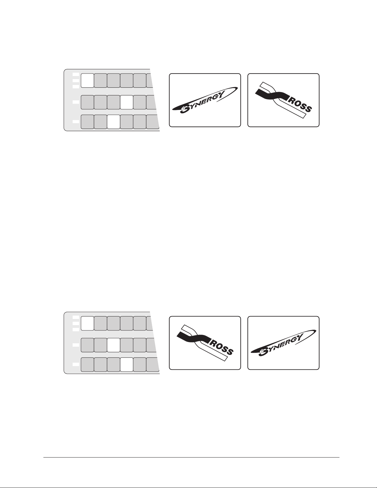
4. Press CUT. The inputs selected on the PGM and PST buses instantly exchange and the
buses flip-flop. The figure below illustrates the MLE and monitor setup after the cut.
KEY1
KEY2
DSK
PGM
PST
BLACK
BLACK
BLACK
CAM
1
CAM
1
CAM
1
CAM
2
CAM
2
CAM
2
VTR1VTR
VTR1VTR
VTR1VTR
VTR
3
2
VTR
2
3
VTR
2
3
Preview Monitor
(CAM 2)
Program Monitor
(VTR 1)
Sample Setup – After a Cut
5. Press CUT again to repeat the process and restore the original background.
This completes the procedure for performing a cut.
Performing Dissolves
In a “background dissolve” transition, the PGM bus video and PST bus video signals are gradually
mixed together, until the PST bus video completely replaces the PGM bus video.
“Using Wipes” on page 6–6 for complete instructions on performing wipe transitions.
Although we have used BKGD transitions between the PGM and PST buses as examples in the
following procedure, remember that all types of transitions operate in the same manner, regardless of
the Next Transition buttons selected.
Refer to the section
Use the following procedure to perform a dissolve:
1. Select an input on the PGM bus.
2. Select a different input on the PST bus.
3. In the Next Transition Section, select BKGD as the next transition. The figure below
illustrates a sample setup and the associated monitor outputs — before the dissolve.
KEY1
KEY2
DSK
PGM
PST
BLACK
BLACK
BLACK
CAM
1
CAM
1
CAM
1
CAM
2
CAM
2
CAM
2
VTR1VTR
VTR1VTR
VTR1VTR
VTR
3
2
VTR
3
2
VTR
2
3
Sample Setup – Before the Dissolve
Preview Monitor
(VTR 1)
Program Monitor
(CAM 2)
Synergy 100 MD Operator’s Manual (v7.2 MD-S100) Transitions • 5–11
Page 92

4. In the Transition Type Section, press DISS.
5. To perform a manual transition, move the Fader from limit to limit. To perform an auto
transition, press the AUTO TRANS button. During either transition, the PST bus video
signal gradually mixes into the PGM signal, as shown below.
KEY1
KEY2
DSK
PGM
PST
KEY1
KEY2
DSK
PGM
PST
BLACK
BLACK
BLACK
BLACK
BLACK
BLACK
CAM
1
CAM
1
CAM
1
CAM
1
CAM
1
CAM
1
CAM
2
CAM
2
CAM
2
VTR1VTR
VTR1VTR
VTR1VTR
VTR
3
2
VTR
2
3
VTR
2
3
Preview Monitor
(CAM 2)
Program Monitor
(VTR 1)
Sample Setup – Performing a Transition
At the end of the transition, the PST video completely replaces the PGM video and the
buses flip-flop. The figure below illustrates the MLE and monitor setup after the
dissolve.
CAM
2
CAM
2
CAM
2
VTR1VTR
VTR1VTR
VTR1VTR
VTR
3
2
VTR
3
2
VTR
2
3
Preview Monitor
(CAM 2)
Program Monitor
(VTR 1)
Sample Setup – After the Dissolve
Note
If a very short auto transition rate is selected (typically five frames or
less), this may appear the same as a cut. This type of transition is often
called a “soft cut”.
This completes the procedure for performing a dissolve.
Performing a Transition Limit Effect
The TRANS LIMIT button in the Transition Control Group allows you to stop a transition at a
position in between the two absolute Fader limits.
Note
Use the following procedure to perform a transition limit effect:
1. Ensure the Fader is at an upper or lower limit and note the limit that you choose. The
5–12 • Transitions Synergy 100 MD Operator’s Manual (v7.2 MD-S100)
If you have the MultiDSK option installed, refer to the section
“MultiDSK Operation” on page 7–35 for information on performing
transitions.
Fader must be returned to this limit in a subsequent step.
Page 93

2. Select a dissolve or a wipe as your next transition.
3. Move the Fader and manually set the transition to the desired position.
• In the case of a dissolve, visually set the desired mix (superimposition) between
Program and Preset.
• In the case of a wipe, visually set the desired split screen position between Program
and Preset.
4. Leave the Fader at its preset position and press TRANS LIMIT. The button lights
momentarily and the fader position is stored.
5. Move the Fader back to the limit selected in step 1.
6. Press TRANS LIMIT to turn on the Transition Limit function. A single LED in the
Transition Progress Bar flashes, corresponding to the manually set position in step 3.
7. Use the AUTO TRANS button to perform the transition. The transition moves to the
limit that you selected in step 3 and stops.
8. There are two ways to continue the transition:
• Leave the TRANS LIMIT button turned on. When you use the AUTO TRANS
button again, the transition reverses — and returns to its starting point.
• Turn off the TRANS LIMIT button. When you use the Fader or AUTO TRANS
again, the transition continues to its end.
This completes the procedure for performing a transition limit effect.
Performing a Transition Preview
The “transition preview mode” allows you to rehearse a complete preset-to-background transition
without affecting the program output. When in this mode, the full transition occurs on Preview,
leaving the Program output signal undisturbed. You can create, rehearse, and preview any transition.
With the transition preview mode engaged, the Fader is effectively disconnected from program.
Operating
Tip
Use the following procedure to perform a Transition Preview:
1. Select the desired Next Transition button or buttons, depending on which video
2. Press and hold the desired Transition Type button, and use the Fader or AUTO
3. Once you are satisfied with the effect, release the Transition Type button. The preview
4. Perform the transition on air. The program output shows the exact effect as previewed
Note
Transition preview mode is allows you to preview complete effects
before taking them on-air.
elements you want to change.
TRANS to preview the current effect. Make any modifications desired.
monitor reverts back to its look-ahead preview mode.
previously on the preview monitor using “transition preview mode”.
If there is a transition in progress when the Transition Type button is
released, the preview monitor output will not return to its look-ahead
preview mode until the transition is complete.
This completes the procedure for performing a Transition Preview.
Synergy 100 MD Operator’s Manual (v7.2 MD-S100) Transitions • 5–13
Page 94

Performing a Preset Black Transition
The Preset Black function is a special two-stage transition that allows you to take the switcher to
black (or any other desired source) with the first transition, and then proceed to the next transition
previously indicated. This function is quite useful for dipping the switcher to black or transitioning to
a commercial.
Pressing PST BLACK causes the BLACK crosspoint to be selected on the PST bus, replacing the
currently selected PST source. The buttons in the Next Transition Section may change, depending on
what is currently on air.
Note
If you have the MultiDSK option installed, refer to the section
“MultiDSK Operation” on page 7–35 for information on performing
transitions.
Preset Black Overview
There are two stages to a Preset Black transition:
• When you press PST BLACK, the switcher presets a dissolve to black. An alternate
transition type can be selected, if desired. If a key or a combination of keys are on, but
their “next transition” buttons are not lit, the switcher automatically lights the button for
you.
The first transition dissolves the switcher to black and dissolves off all keys. The
buttons in the Next Transition Section then change, presetting the switcher with the
original preview scene. This scene now appears on the Preview monitor.
• The second transition brings the switcher back up from black to the scene previously
shown on Preview — regardless of the combination of background and key sources
selected.
Performing a Preset Black Transition
Use the following procedure to perform a Preset Black transition:
1. Press PST BLACK. The preview monitor will now show a black picture.
2. Perform a transition with the Fader, AUTO TRANS, or CUT. The program transitions
to black. Note that when black is reached, the switcher presets the scene previous to the
black picture, and displays it on Preview.
3. Perform a second transition using the Fader, AUTO TRANS, or CUT. The switcher
transitions to the previous scene, at the end of which the PST BLACK light turns off.
Operating
Tip
This completes the procedure for performing a Preset Black transition.
5–14 • Transitions Synergy 100 MD Operator’s Manual (v7.2 MD-S100)
After Step 1, a different source other than black can be selected on
PST. This would allow you to dip to COLOR BKGD (white, for
example), for a creative “flash-frame” transition. In addition, BLACK
can be permanently overridden by holding down the PST BLACK
button while selecting the desired source on the PST bus.
Page 95

Pattern and Effects Control
In This Chapter
This chapter provides information and instructions for using the Effects Control Group of the
switcher. The following topics are discussed:
• Effects Control Groups
• Effects Control Modes
•Wipes
• Using Wipes
• Selecting Wipes
• Mattes Group
Synergy 100 MD Operator’s Manual (v7.2 MD-S100) Pattern and Effects Control • 6–1
Page 96

Effects Control Groups
The two Effects Control Groups are assignable groups of controls that allow you to choose wipe
patterns, and adjust wipe parameters and key modifiers. For example, by pressing WIPE, or FLY
KEY, the groups are assigned to that specific function.
The top Effects Control Group includes a four-character display labeled “MODE”, and its
associated SEL button. This display identifies which area or button on the switcher has control of the
Effects Control Groups. In addition, the button of the controlling feature (for example, WIPE or
FLY KEY) will illuminate green, instead of yellow.
The following figure illustrates the Effects Control Groups on the Synergy 100 MD control panel:
EFFECTS CONTROL MATTES SYSTEM CONTROL
SEL
CNTR
REV
506172839
MATTE
SELF
MASK
FLY
FILL
KEY
AUTO
KEY
SELECT
KEY
INVERT
ROTATE
ASPECT
MEM
ASPECT
CHROMA
KEY
KEY2
PST
PATT
ON AIR
4
TRANSP
DVE
MATTESEFFECTS KEYERSEFFECTS CONTROL
HUE/
HUE
GAIN
SAT
CLIP
LUM CLIP GAINSOFT BORDER
EDIT
KEY
MEM
SELF
KEY
MASK
BACKMENUSEL
100 10 1
DOWNSTREAM KEYER
MATTE
FILL
AUTO
CHAR
SELECT
GEN1
KEY
INVERT
SHDWBORD OUTL
CHAR
GEN2
SEL
DSK
PV
KEY1
KEY2
BLACK SHIFT
DSK
PGM
BLACK
PST
BLACK
BUSY
Effects Control Groups
Effects Control Modes
SEL
• The SEL button in the Effects Control Group allows you to cycle through several
“modes”, depending on the area or button which currently has control of the Effects
Control Groups. The modes displayed are linked to the area or button selected, as
outlined in the table on the following page.
In addition, by holding down the SEL button and pressing one of the buttons listed in
the following table, you can change the button that has control without having to toggle
it on and off.
Note
The Squeeze & Tease WARP MD, and Dual Border Generator
options are not available at this time.
SHIFT
SHIFT
BKGD KEY1 KEY2
ON AIR ON AIR ON AIR ON AIR
DISS
WIPE
DVE
AUTO
CUT
TRANS
TRANSITION CONTROL
TRANS
LIMIT
DSK
CUT
ON AIR
PST
BLACK
FADE
TO
BLACK
DSK
DISS
6–2 • Pattern and Effects Control Synergy 100 MD Operator’s Manual (v7.2 MD-S100)
Page 97

Effects Control Mode Table
Mode Button Selected Features Controlled
FLY1 FLY KEY in Effects Keyer, Key 1 (*1) (*3) Size, aspect ratio, and position of flown key in
Keyer 1
FLY2 FLY KEY in Effects Keyer, Key 2 (*1) (*3) Size, aspect ratio, and position of flown key in
Keyer 2
CRP1 MASK when a Squeeze & Tease MD Box is
active in Effects Keyer, Key 1
CRP2 MASK when a Squeeze & Tease MD Box is
active in Effects Keyer, Key 2
MSK1 MASK in the Effects Keyer, Key 1 (*2) Masking areas of a Self, Auto Select, or
MSK2 MASK in the Effects Keyer, Key 2 (*2) Masking areas of a Self, Auto Select, or
MSKd MASK in the Downstream Keyer Group Masking areas of a Self or Auto Select key in
MEM“#” MEM in the Effects Control Group Access to the Memory Store and Recall features
WIPE WIPE in the Transition Control Group All Wipe controls, including pattern selection
Cropping all edges of the video in a Squeeze &
Tease MD Box on Key 1
Cropping all edges of the video in a Squeeze &
Tease MD Box on Key 2
UltraChrome Chroma key on Key 1
UltraChrome Chroma key on Key 2
the Downstream Keyer
and modifiers
PP1 PST PATT (with FLY KEY off) in Effects
Keyer, Key 1
PP2 PST PATT (with FLY KEY off) in Effects
Keyer, Key 2
DVE DVE in the Transition Control Group Pattern selection and wipe direction for the
BORD BORD, SHDW, or OUTL in the Downstream
Keyer Group
ACK1 CHROMA KEY in Effects Keyer, Key 1 The Auto Chroma Key feature when setting up
ACK2 CHROMA KEY in Effects Keyer, Key 2 The Auto Chroma Key feature when setting up
NONE *see next column If any of the above features have control,
HIDE and SHOW SEL to the left of the “Mode” display toggles
between the two modes. (*4)
All modifiers for the Preset Pattern key type on
Key 1
All modifiers for the Preset Pattern key type on
Key 2
Squeeze & Tease MD wipes
All modifiers (softness, size, etc.) for the
optional border generator on the DSK
an UltraChrome Chroma Key on Key 1
an UltraChrome Chroma Key on Key 2
turning them off will set the mode to NONE.
When in any Squeeze & Tease MD menu,
sections of the menu can be hidden. If the mode
is set to “HIDE”, only the currently selected
item, and its corresponding data values will
remain displayed. “SHOW” displays the entire
S&T MD menu and all data values.
Notes:
(*1) Selecting PST PATT in the keyer automatically turns on the FLY KEY.
(*2) Except when the key type is a Squeeze & Tease MD Box.
(*3) If you have the Squeeze & Tease WARP MD option installed, the key can also be
rotated.
(*4) Only valid when in the S&T MD Menu.
Synergy 100 MD Operator’s Manual (v7.2 MD-S100) Pattern and Effects Control • 6–3
Page 98

Wipes
CNTR
E
F
F
D
The Effects Control Groups also include two pattern generators:
• Pattern Generator 1 is shared by the Wipe Generator and the Preset Pattern
Generator for KEY1 of the Effects Keyers. This pattern generator is full-featured —
all wipe patterns are available.
Note
The Star and Heart patterns and the Matrix Wipes are currently not
implemented.
• Pattern Generator 2 is used by the Preset Pattern Generator for KEY2 of the Effects
Keyers. This generator is restricted to the Classic wipe patterns, minus the circle, and
the Rotary wipe patterns. Matrix wipes are not available.
Note
Because Pattern Generator 1 is shared, you cannot select a WIPE
transition if PST PATT is selected on Keyer 1. Similarly, if WIPE is
enabled and you select a PST PATT key type in Keyer 1, the WIPE
button turns off and the transition type reverts to DISS.
The top Effects Control Group includes 10 buttons which display 10 “classic” wipes. In addition,
each button provides access to any of the more than 60 “user” wipes available.
To select a wipe, press WIPE in the Transition Control Group and select the desired pattern button.
Once selected, the pattern can be modified and used on air. A single press of a button will illuminate
its LED, and select the wipe as pictured. If you double-press the button, the LED will flash, indicating
“user wipe mode”, and you will be able to choose any of the more than sixty wipes available.
Also included in the top Effects Control Group are the following two buttons:
• The REV/LEARN button controls the direction of the wipe. Three choices of wipe
L
REV
E
A
R
N
directions are available:
~ The default state of the REV/LEARN button is off. The wipe will proceed in the
normal fashion, with the new picture being revealed from the black area (as shown
on the pattern button) to the white area. The button’s LED will not be lit.
~ Press REV/LEARN to set the direction of the wipe to reverse. The new picture is
revealed from the white area to the black area. The button’s LED will be on.
~ Double-press REV/LEARN to set the direction of the wipe to “flip-flop”. Wipe
direction is normal for the first transition, reverse for the second, then normal for the
third, etc. The button’s LED will be flashing.
• The CNTR/EFF D button is used to return borders, wipe positions, masks, and cropping
features to their default state or position. In addition, it is used to default flying keys,
including Squeeze & Tease boxes, to full screen. When recalling memories, this button
enables you to perform an “effects dissolve” between two switcher setups.
6–4 • Pattern and Effects Control Synergy 100 MD Operator’s Manual (v7.2 MD-S100)
Page 99

The lower Effects Control Group provides two buttons and three “end-stop” knobs that modify the
selected pattern.
Important
Operating
Tip
• The BORDER knob allows you to adjust pattern borders, from no border to full-screen
BORDER
• The SOFT knob allows you to adjust pattern edge softness from hard-edge to full
SOFT
Because the electrical position of an End-stop Knob can be
overwritten by recalling a memory register, the electrical knob position
may not match the knob’s current physical position. In this case, the
knob can still be adjusted but you may not have the full adjustment
range available.
To fully re-synchronize the physical-to-electrical position of an
End-stop Knob, turn the knob fully clockwise, then fully
counter-clockwise. Full-range adjustments can now be made.
borders on all wipe patterns, with the exception of pattern number 111, which does not
accept a border. Refer to the section “Selecting Wipes” on page 6–7 for information on
how to access additional patterns.
~ Turning the knob clockwise increases border width.
~ Turning the knob counter-clockwise decreases border width.
soft-edge on all patterns, with the exception of pattern number 111, which does not allow
edge softness. Refer to the section “Selecting Wipes” on page 6–7 for information on
how to access additional patterns.
~ Turning the knob clockwise increases edge softness.
~ Turning the knob counter-clockwise decreases edge softness.
•When the ASPECT button is lit, the adjacent knob can be used to adjust the aspect ratio
of selected patterns.
ASPECT
~ Turning the knob clockwise increases the pattern’s vertical aspect ratio, and, at the
same time, reduces the horizontal aspect ratio.
~ Turning the knob counter-clockwise increases the pattern’s horizontal aspect ratio,
and, at the same time, reduces the vertical aspect ratio.
• The ASPECT button enables the use of the adjacent knob.
ASPECT
~ When the button is on, patterns with both horizontal and vertical angles to their
edges can have their aspect ratios adjusted. Circles can be adjusted into ovals,
squares into rectangles, etc.
~ When the button is off, all aspect ratio adjustment is removed and the pattern returns
to its default shape.
Note the following points regarding the ASPECT button:
• If you adjust the aspect ratio of one pattern, then select another pattern that can not have
its aspect adjusted, the ASPECT light will stay on until it is turned off manually by
pressing the button.
• The ROTATE button enables the use of the positioner as a wipe pattern modifier.
ROTATE
~ When the button is on, certain patterns can be rotated a full 360 degrees.
~ When the button is off, all rotation is removed and the pattern returns to its default
position.
Synergy 100 MD Operator’s Manual (v7.2 MD-S100) Pattern and Effects Control • 6–5
Page 100
Using Wipes
In a “background wipe” transition, the PGM bus video is gradually replaced with the PST bus video
according to a wipe pattern pre-selected in the Effects Control Group.
Use the following procedure to perform a wipe:
1. Select an input on the PGM bus.
2. Select a different input on the PST bus.
3. In the Tra n s i t i o n Co n t r o l Group, select BKGD as the next transition. The following
figure illustrates a sample setup and the associated monitor outputs — before the wipe.
KEY1
KEY2
DSK
PGM
PST
BLACK
BLACK
BLACK
CAM
1
CAM
1
CAM
1
CAM
2
CAM
2
CAM
2
VTR1VTR
VTR1VTR
VTR1VTR
VTR
3
2
VTR
2
3
VTR
2
3
Preview Monitor
(VTR 1)
Program Monitor
(CAM 2)
MLE and Monitor Setup – Before the Wipe
4. Press WIPE. This action causes the lamp on the WIPE button to illuminate yellow and
automatically assigns the Effects Control Groups to the transition.
5. Press the pattern button for the desired wipe.
6. Choose the direction for the wipe. Select between normal, reverse, or flip-flop by
pressing or double-pressing the REV/LEARN button.
7. Turn the BORDER knob fully clockwise, then fully counterclockwise. For this first
exercise, this ensures that there is no border.
8. To perform a manual transition, move the Fader from limit to limit. To perform an auto
transition, press the AUTO TRANS button. During the transition, the PST bus video
signal gradually replaces the PGM signal using the selected wipe, as the following
figure illustrates.
KEY1
KEY2
DSK
PGM
PST
BLACK
BLACK
BLACK
CAM
1
CAM
1
CAM
1
CAM
2
CAM
2
CAM
2
VTR1VTR
VTR1VTR
VTR1VTR
VTR
3
2
VTR
3
2
VTR
2
3
Preview Monitor
(VTR 1)
Program Monitor
(VTR 1 and CAM 1)
MLE and Monitor Setup – Performing a Transition
At the end of the transition, the PST video completely replaces the PGM video and the
buses flip-flop.
6–6 • Pattern and Effects Control Synergy 100 MD Operator’s Manual (v7.2 MD-S100)
 Loading...